1
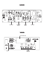
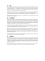
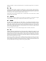
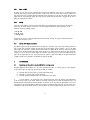
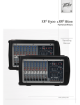
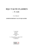
®
TLAudio
user manual
Ivory 2 Series
5060
PRESET VALVE COMPRESSOR
TL Audio Ltd, Letchworth, Herts, SG6 1AN, UK
email: [email protected] web: http://www.tlaudio.co.uk
CONTENTS
1.
INTRODUCTION
2.
PRECAUTIONS
3.
3.1
3.2
3.3
3.4
3.5
3.6
3.7
3.8
INSTALLATION
A.C. Mains Supply
Microphone Input
Line Inputs
Instrument Inputs
Balanced Line Outputs
Unbalanced Line Outputs
Nominal Operating Level
Ventilation
4.
4.1
4.2
4.3
4.4
4.5
4.6
4.7
4.8
4.9
4.10
4.11
4.12
4.13
4.14
4.15
4.16
4.17
4.18
4.19
4.20
4.21
OPERATION
What is Compression?
Why Valve Compression?
Overview of Compressor Operation
Input Source Selection
Mic Gain
Input Gain
90Hz Low Cut Filter
Drive & Peak LEDs
Program Control
Table 1: Presets
Threshold
Ratio
Attack and Release
Gain Make Up
Knee
Comp On
Output Gain
Meter
Meter ‘+10dB’
Fat EQ
DO-2 Digital Output Card
5.
5.1
5.2
5.3
GETTING STARTED
Connections
In Use
Frequently Asked Questions (FAQs)
6.
SERVICE
7.
SPECIFICATIONS
FIG 1: BLOCK DIAGRAM
1.
INTRODUCTION
Congratulations on purchasing the Ivory 5060 Preset Valve Compressor by TL Audio!
The Ivory 2 Series consists of a range of hybrid valve signal processors, which utilise low noise solid-state electronics in
conjunction with classic valve circuitry to produce audio processing units offering very high quality signal paths with the
unique valve audio character. The units offer comprehensive control facilities, whilst remaining straightforward to operate, and
represent excellent value for money.
The 5060 is a dual channel processor with a single balanced mic input and stereo line inputs/outputs on the rear panel, and
stereo instrument inputs on the front panel. The 5060 features a compressor section with 15 presets and a ‘manual’ mode,
plus a “Fat EQ” switch that, when active, applies an EQ contour to both channels. The two channels of the 5060 work in
‘linked stereo’ mode, but a mono signal can be applied to channel 1 only, making the 5060 equally powerful for both
mono/stereo tracking and final stereo mix processing. A single illuminated VU meter monitors the output level or the
compressor gain reduction for both the channels. The optional DO-2 digital output card allows 24-bit A to D conversion via
an RCA phono type SPDIF output, with selectable 44.1 or 48 kHz sample rates and an external word clock connection.
The block diagram of the 5060 is shown in Figure 1. A solid state, electronically balanced input amplifier is used to achieve
state of the art performance with very low noise, low distortion and wide bandwidth. An ECC83/12AX7A triode valve stage
(run from a stabilised 100v DC supply) is used as a second stage voltage amplifier, to obtain the classic valve sound and
gradual overdrive characteristics. The preamp stage also features 48V phantom power and a high pass 90Hz filter. A Drive LED
gives a visual indication of the signal level through valve stages (and thus the amount of ‘warming’ taking place) while a
Peak LED warns that clipping is about to occur.
The compressor section offers 15 carefully prepared presets designed to work with a variety of suggested signal sources. The
compressor also has a manual mode, in which the dedicated compressor controls become active. In preset mode these controls
are disabled with the exception of the “Compressor On” switch and the “Gain Make-Up” control. Manual mode features fully
variable control of threshold, ratio and gain make-up with switchable fast/slow attack and release settings and hard/soft knee
options. Like all other TL Audio compressors, the gain control element of the 5060 is based around a special transconductance
amplifier, which avoids the use of VCAs and helps contribute to the smooth, open sound of the unit, along with the valve
stage that forms part of the preamp circuit.
After the compressor section - but prior to the output gain control - the Fat EQ facility adds a gentle boost to the low and
high-end frequencies while introducing a slight dip in the mid range frequencies. The effect of this is to add a subtle
“sweetening” or “fattening”, similar to the ‘Loudness’ button on Hi-Fi systems, thus adding a touch of “weight” to the signal.
The 5060 Mic input is provided on an electronically balanced XLR connector, and the line inputs are provided on balanced
TRS stereo 0.25” jack connectors. Balanced and unbalanced line outputs are provided (again on TRS 0.25” jack connectors)
and these can be used simultaneously. The operating level of both the line input and outputs can be shifted from -10dB to
+4dB via a rear panel switch, allowing the 5060 to easily integrate into any system. A pair of high impedance front panel
instrument inputs allow guitars, basses and keyboards to feed directly into the 5060, removing the need for a separate DI
box.
Please read this manual fully before installing or operating the 5060.
2
2.
PRECAUTIONS
The 5060 Preset Valve Compressor requires very little installation, but like all electrical equipment, care must be taken to
ensure reliable, safe operation. The following points should always be observed:
- All mains wiring should be installed and checked by a qualified
electrician,
- Ensure the correct operating voltage is indicated on the rear panel
before connecting to the mains supply,
- Never operate the unit with any cover removed,
- Do not expose to rain or moisture, as this may present an electric
shock hazard,
- Replace the fuse with the correct type and rating only.
Warning: This equipment must be earthed.
3
FIG 2: FRONT PANEL
PREAMP SECTION
PRESET PROGRAM
SELECTOR
COMPRESSOR
SECTION
FIG 3: REAR PANEL
SLOT FOR OPTIONAL DO-2 CARD
IEC INLET
INPUT / OUTPUT
CONNECTIONS
OUTPUT SECTION
3.
INSTALLATION
3.1
AC Mains Supply.
The 5060 is fitted with an internationally approved 3-pin IEC connector. A mating socket with power cord and mains plug is
supplied. All mains wiring should be performed by a qualified electrician with all power switched off, and the earth connection
must be used.
Before connecting the unit to the supply, check that the 5060 is set for the correct mains voltage. The unit is internally set
for 110-120V 60Hz or 220-240V 50Hz operation, and should only be changed by an authorised service centre. The mains fuse
required is 20mm anti-surge, 315mA rated at 250V. If it is ever necessary to replace the fuse, only the same type and
rating must be used. The power consumption of the equipment is 30VA.
Warning: attempted operation on the wrong voltage setting, or with an incorrect fuse, will invalidate the warranty.
3.2
Microphone Input.
The microphone input is via 3 pin female XLR connector, suitable for balanced microphones. The mating connector should be
appropriately wired as follows:
Balanced inputs:
- Pin 1 = Ground (screen).
- Pin 2 = Signal Phase (also known as “+” or “hot”).
- Pin 3 = Signal Non-Phase (“-” or “cold”).
The single microphone input of the 5060 is automatically routed to both channels of the unit.
3.3
Line Inputs.
Each channel has a 3 pin TRS jack socket on the rear panel, which will accept balanced or unbalanced line inputs providing
the mating plug is suitably wired:
Balanced inputs:
- Screen = Ground,
- Tip = Signal Phase (“+” or “hot”),
- Ring = Signal Non-Phase (“-” or “cold”).
4
Unbalanced inputs:
- Screen = Ground,
- Tip = Signal Phase (“+” or “hot”),
- Ring = Ground.
Good quality screened cable should be used, particularly for microphone or low level sources, to prevent hum or noise pickup.
Refer to Figure 3 for rear panel connector identification.
Please note that if a mono source is connected to line input 1 only, it will be automatically routed to both channels of the
5060.
3.4
Instrument Inputs.
Each channel has a high impedance (1Mohm) 0.25” instrument jack socket on the front panel (see Figure 2). A 2 pin
(mono) jack plug is required, which should be wired as follows:
- Tip =
Signal Phase (“+” or “hot”),
- Screen = Ground.
Please note that if a mono source is connected to instrument input 1 only, it will be automatically routed to both channels
of the 5060.
3.5
Balanced Line Outputs.
The line outputs are via 3 pin TRS jack sockets on the rear panel, and may be configured for balanced or unbalanced
connection. Balanced operation is always preferable to maintain maximum headroom and signal to noise ratio, but can only
be used if the following equipment is also capable of balanced operation:
Balanced outputs:
- Screen = Ground,
- Tip = Signal Phase (“+” or “hot”),
- Ring = Signal Non-Phase (“-” or “cold”).
Unbalanced outputs:
- Screen = Ground,
- Tip = Signal Phase (“+” or “hot”),
5
- Ring = Ground.
3.6
Unbalanced Line Outputs.
An dedicated unbalanced line output is provided for each channel, on a 0.25” mono jack socket.
- Tip =
Signal Phase (“+” or “hot”).
- Screen = Ground.
These outputs may be used simultaneously to the balanced line outputs, and are useful for monitoring purposes particularly in
a computer based system where latency free monitoring is necessary.
3.7
Nominal Operating Level.
A switch on the rear panel allows the line inputs and outputs to be matched to equipment at a nominal operating level of
+4dBu or -10dBu. Most professional equipment requires +4dBu (approximately 1.2V rms), but some small mixing consoles,
portable tape recorders or domestic audio equipment require -10dBu (approximately 225mV rms). If the operating level is
not known, the switch should be set to the position which results in the best signal to noise ratio, whilst preserving sufficient
headroom.
3.8
Ventilation.
The 5060 generates a small amount of heat internally, mainly due to the valve heater. Do not locate the compressor where
it will be subject to external heating, for example, in the hot air flow from a power amplifier or on a radiator.
4.
OPERATION
4.1
What is Compression?
Compression is an essential but often misunderstood process in modern recording. Put simply, compression reduces the ratio
between the loudest and the quietest levels of an audio signal, which is known as reducing the “dynamic range” of that
signal. Before the introduction of compressors the only way this could be achieved was by “gain riding”, whereby an engineer
would control the fader manually in order to try and anticipate very large levels (which might distort the signal) or very low
levels (which may get lost in noise). The introduction of compression devices meant that this process could be controlled
automatically, allowing the engineer to get on with more productive jobs!
Many instruments and voices have a very wide dynamic range, which needs to be controlled. A singer, for instance, may be
singing quietly one moment and very loudly the next, and unless compression is applied the vocal won’t “sit” correctly in the
mix, in addition to the problems of distortion on loud passages and noise on quiet ones. Thus with compression you are
effectively turning down the loud bits and turning up the quiet bits, to achieve a more even and controllable level.
But there are other benefits of compression as well - applied properly, it can add punch and excitement to music, as well as
fattening up sounds and creating a more professional sounding recording. With the 5060, you have the added benefit of valve
stages in the signal path, which create a warmth and presence just not obtainable with solid state or digital products.
6
4.2
Why Valve Compression?
Valve compression yields a particularly special sound, which has become very sought after, particularly with the widespread use
of digital products. The reason valve equipment sounds special is due to two things: harmonic distortion and natural
compression. When the signal through a valve is increased, it tends to generate a particular type of subtle and desirable
distortion, called “second harmonic” distortion. This has the effect of thickening and warming the sound, and the more the
level you feed to the valve stages, the more of this harmonic distortion will be produced. You should be able to hear this
effect as you increase the Input Gain on the 5060.
Secondly, valves will tend to naturally compress an audio signal, again particularly as the signal level is increased. This itself
also contributes to the warmth produced by the 5060.
4.3
Overview of Compressor Operation.
The 5060 offers two distinct ways of working: manual or preset modes. In manual mode, all the compressor controls are
active and adjustable, so that compression settings can be created from scratch to suit the user’s taste. In the fifteen preset
modes, the Threshold, Ratio, Attack, Release and Knee controls are disabled and each is fixed internally at a value that is
selected to give the best results with that particular instrument (the presets are titled ‘vocal’, ‘bass’, ‘guitar’, ‘snare’ etc. to
indicate the recommended application).
The 5060 functions by reducing the gain of the signal when it rises above a certain level, known as the Threshold. Any signal
below the threshold passes through the unit unaffected. Above the threshold the gain of the signal is reduced, and the degree
of gain reduction is determined by the Ratio control. The Ratio control is calibrated in dBs and is simply the change in
output level that results from a given change in input level.
The Attack and Release switches are used to control how fast the compressor reacts to the audio signal. The Attack switch
governs how quickly the 5060 acts to compress the signal once it has risen above the threshold, while the Release switch
controls how quickly the signal returns to normal once it has dropped back below the threshold level.
The Knee switch controls the shape of the 5060 compression curve. In “Soft Knee” mode, the response curve of the
compressor around the threshold is gentle, so that the compression effect is more subtle and musical. In “Hard Knee” mode,
the curve is more severe, so that signals above the threshold are “squashed” more aggressively. This yields a more audible
and pronounced compression effect.
The Gain Make-Up control is positioned at the output of the compressor stage, and allows the signal level to be brought back
to the same loudness as the uncompressed signal.
4.4
Input Source Selection.
The input source and phantom power selection are controlled on a four position rotary switch. The selections are:
MIC +48V:
For condenser mics that require 48V phantom power
MIC:
For most dynamic or ribbon mics
LINE:
Line inputs
INST:
Front panel Instrument inputs
CAUTION: Never switch phantom power on or off, or plug/unplug a microphone with phantom power applied unless the
output level control is turned down. Failure to do so may result in a thump in your monitor loudspeakers or PA system.
7
4.5
Mic Gain.
The Mic Gain control sets the level of the microphone input signal prior to the Input Gain control. There are 4-switched level
positions: -20, 0, +20 and +40dB, with a further +/- 20dB available on the Input Gain control. For normal operation it is
recommended to keep the Mic Gain setting at the +40dB position, with any fine adjustments to the input signal level made
by either boosting or reducing the Input Gain control. Keeping the Mic Gain at its maximum setting (+40dB) helps to keep
the noise figures as low as possible. For extremely high-level signal sources - such as close-mic’d drums - it may be necessary
to reduce the Mic Gain position to prevent input overload.
4.6
Input Gain.
The Input Gain control sets the level of the signal fed to the input stage of the compressor, and is variable between -20dB
and +20dB. This allows a wide range of signals to be fed into the 5060, and also allows the valve stages to be driven to a
variable degree. Each channel of the 5060 has a triode valve stage positioned between the input circuit and the compression
stage. Increasing the input gain pushes more signal level into the valve, thus generating more harmonic distortion and
creating that special “valve sound”. At the same time the output level can be turned down to preserve the same level at the
outputs, so a choice of sounds is available. For a more pronounced valve sound, turn up the input gain and reduce the
output gain, and vice versa for a cleaner sound. Don’t be afraid to push the 5060 hard!
As well as driving the valves harder, increasing the Input Gain control setting will also tend to push the signal towards and
possibly over the compression threshold setting, so this control will have a pronounced effect on the amount of compression
taking place, even in the Preset modes.
The Input Gain control is active at all times, whether the Program control is set to Manual or Preset modes.
4.7
90 Hz Low Cut Filter.
The low cut (high pass) filter switch restricts the low frequency response of the preamp, to effectively remove rumble or LF
noise from the signal. The filter can be useful in restricting “popping” on vocals or even low frequencies caused by contact
with microphone stands or microphone cables. Popping is an undesirable thump that is caused by close-miking certain spoken
or sung letters, namely “P” or “B”. These particular letters cause a sudden expulsion of air that can result in an audible
thump. As this thump has a lot of low frequency content the high pass filter can help to reduce the problem, as can using a
pop filter (a device usually made out of nylon material similar to stockings) suspended in front of the microphone. The 90Hz
filter is active on mic, line and instrument inputs.
4.8
Drive and Peak LEDs.
The yellow Drive LED provides a visual indication of the signal level through the valve stages, and therefore the extent of
“warming” or valve character being introduced. The Drive LED will gradually illuminate as the input level or gain is increased,
over the range 8dB to +18dB.
The red Peak LED operates as a conventional warning that clipping is about to occur. The operating level of the entire signal
chain is monitored, and the LED illuminates when there is less than 6dB of headroom remaining. Normal operation would be
to set the input gain so that the Drive LED is regularly illuminating, with occasional lighting of the Peak LED on transients.
However, it is possible to add gain further down the 5060 signal path which will cause the Peak LED to illuminate at a lower
level of Drive. This situation implies that a high level of “clean” signal is present, without driving the valves hard.
8
4.9
Program Control.
This 16-way rotary switch enables factory preset compression settings to be selected for different types of audio signal. The
‘Manual’ mode enables the Threshold, Ratio, Attack, Release, and Knee controls to be adjusted, along with the Input Gain,
Output Gain and Gain Make Up controls (which are active at all times). In this mode the 5060 works like a standard
compressor in the sense that the user can create their own unique compression setting and have full control over it at all
times.
In all the other 15 program settings, the Threshold, Ratio, Attack, Release and Knee controls are pre-selected and fixed within
the 5060 to give optimum results for that given type of signal. Thus these controls are disabled and will have no effect when
adjusted, unless the user returns to ‘Manual’ mode. In the Preset modes, all the user has to do is select the required preset
and then adjust the Input Gain, Output Gain and Gain Make Up to taste (see particularly section 4.6 on Input Gain). The 15
presets are shown in Table 1.
The way the Program control works is by using a digital switching circuit to replace the controls mentioned by a series of
fixed components (in the case of Threshold and Ratio) and on/off switch values (in the case of Attack, Release and Knee). This
doesn’t mean that the signal itself is converted to digital format within the 5060: it simply means that the signal parameters
are controlled digitally.
How did we create the Program settings? Simply by operating the unit in Manual mode and arriving at an optimum set of
adjustments for vocals, keyboards, basses, guitars, drums and stereo mixes. These settings were then programmed into the
5060, and as a result we’ve detailed the settings for each preset in Figure 4, should you wish to re-create any of the presets
in manual mode, and adjust them to suit your own application. The designated presets can work with other signal types, so
don’t be afraid to experiment.
9
4.10
Table 1: Presets.
Number
Preset Title
Typical Applications
1
Whisper Vox
2
Pop Vox
3
Rock Vox
4
Scream Vox
5
Keys
6
Bass
7
8
Acoustic Guitar
Electric Guitar
9
10
11
Snare
Kick
Loop
12
Pop Mix
13
Rock Mix
14
Dance Mix
15
Slam Mix
16
Manual
Subtle compression for softer vocal performances. Soft knee, fast attack
and release.
Medium compression for more obvious control. Soft knee, fast attack and
slow release.
Hard compression for powerful performances. Hard knee, fast attack and
slow release.
Even heavier settings for when your local rap metal band do their vocal
takes. Hard knee, fast attack and release.
Medium compression for keyboards especially synth pads. Soft knee, slow
attack and release.
Compression for electric, acoustic and synth basses. Soft knee, slow attack
and release.
Soft knee, fast attack and fast release.
Medium compression for recorded or DI’d guitars. Soft knee, fast attack
and release.
For tight control of snares. Hard knee, fast attack and release.
For tight control of kick drums. Hard knee, slow attack and release.
Ideal for compressing stereo acoustic drum kits, drum machines and
sampler drum loops. Soft knee, fast attack and release.
Lighter compression suitable for light pop, jazz or classical mixes. Soft
knee, fast attack and release.
Medium compression suitable for rock mixes. Soft knee, fast attack and
slow release.
Heavy compression suitable for dance mixes. Hard knee, fast attack and
slow release.
Even heavier compression for maximum-level, minimum- dynamics mixes.
Fast attack and slow release.
For your own set-ups, using the compressor controls.
4.11
Threshold.
The 5060’s compressor functions by reducing the gain of the signal when it rises above a certain level, known as the
Threshold. Any signal below the Threshold passes through the unit unaffected, while signals above the Threshold have their
gain reduced (and are thus ‘compressed’).
The 5060 has a variable Threshold control, adjustable between +10dBu and -20dBu. Unlike some compressors, the Threshold
control on the 5060 starts at a ‘plus’ value in the counter-clockwise position, and decreases to a ‘minus’ value as you rotate
the control clockwise. The reason for this is as you turn the Threshold control on the 5060 `clockwise (i.e. towards the
negative region) then the degree of compression will increase. We think this is logical, whereas the common method of
turning the control ‘down’ to achieve more compression is not - but beware, some other compressors may work in this way!
The Threshold control is only active when the Program control is set to Manual mode. In all of the Preset modes it is
disabled and the Threshold value is fixed internally.
10
Figure 4
PRESETS
1. Whisper
Vox
2. Pop
Vox
3. Rock
Vox
4. Scream
Vox
5. Keys
6. Bass
7. Ac
Guitar
8. El
Guitar
9. Snare
10. Kick
11. Loop
12. Pop
Mix
13. Rock
Mix
14. Dance
Mix
15. Slam
Mix
CONTROLS
Input Gain
Output
Gain
Gain MakeUp
Threshold*
Ratio*
Knee*
Soft
Soft
Hard
Hard
Soft
Soft
Soft
Soft
Hard
Hard
Soft
Soft
Soft
Hard
Hard
Attack*
Fast
Fast
Fast
Fast
Slow
Slow
Fast
Fast
Fast
Slow
Fast
Fast
Fast
Fast
Fast
Fast
Slow
Slow
Fast
Slow
Slow
Fast
Fast
Fast
Slow
Fast
Fast
Slow
Slow
Slow
Release*
* The settings shown for these controls are fixed internally for each preset and are non-adjustable (except in manual mode).
The Input Gain and Output Gain are user adjustable at all times, the Gain Make-up is user adjustable when the compressor is active.
4.12
Ratio.
Once the input signal has crossed the threshold, the degree of gain reduction is determined by the Ratio control. The Ratio
control is calibrated in dBs and is simply the change in output level that results from a given change in input level. An
uncompressed signal will have a 1:1 compression ratio - every 1dB change in input level results in the same 1dB change in
output level. A compression ratio of 1:3, for instance, means that a 3dB change in input level will only give a 1dB change in
output level. For more severe compression, simply turn up the Ratio control.
The 5060 offers a wide range of ratios from 1:1.5 (gentle compression) through to 1:30 (limiting). Limiting effectively clamps
the input signal at the threshold level no matter how much the signal is increased: this can be useful when trying to ensure
that the signal doesn’t exceed a certain level - for instance to prevent a digital recorder distorting through overload.
The Ratio control is only active when the Program control is set to Manual mode. In all of the Preset modes it is disabled
and the Ratio value is fixed internally.
4.13
Attack and Release.
The Attack time of the 5060 is switchable between 0.5mS (‘Fast’) and 5mS (‘Slow’). At 0.5mS attack, the compressor is fast
enough to compress a 1kHz signal in less than half a cycle, effectively preventing the overload of any following equipment
which has limited headroom, such as a digital processor, tape machine or transmitter. Fast attack times are used to compress
a signal quickly, so are suitable for audio signals with sharper transients such as drums. However, if you want the initial
leading edge of the signal retained (for instance the initial click of a bass guitar or bass drum) then a slower attack time can
be employed, and slow attack times can also be useful on sustained sounds like synth pads.
The Release time of the 5060 is switchable between 0.2S (‘Fast’) and 1.5S (‘Slow’). The Release setting is important because if
it is too short, the compressor gain recovers too quickly with the result that there is an audible ‘pumping’, ‘breathing’, and
sometimes low frequency distortion. In these cases try using a slow release time.
Adjustment of the attack and release times allows unobtrusive compression to be applied to virtually any audio signal, but
should very short transients occur the time constants become signal dependent, generally reduced, to prevent a slow release
leaving a ‘hole’ in the signal after the transient. Also, a fast release setting will be extended by a slow attack setting. This
type of automatic control means that the flexibility of the 5060 is greatly extended without the extra complication of fully
variable attack and release controls.
The Attack and Release controls are only active when the Program control is set to Manual mode. In all of the Preset modes
they are disabled and the Attack and Release values are fixed internally.
4.14
Gain Make Up.
While the subjective sound quality of the signal can be improved by compression, the overall signal level will be reduced
when gain reduction is taking place. The Gain Make Up control is designed to boost the compressed signal by between 0 and
+20dB, in order to bring back the level to the same loudness as the uncompressed signal. Without this control, comparing
the original and compressed signals becomes difficult, since there would be a level drop each time the compressor is switched
in: therefore it is normal to adjust the Gain Make Up control so that when the ‘compressor on’ switch is activated, the audio
signal remains constant in level.
Unlike the Output Level control, the Gain Make Up control is active only when the ‘compressor on’ switch is engaged. Once
the Gain Make Up has been adjusted, use the Output Level control to set the overall output level of the 5060.
11
Assuming the compressor is activated, the Gain Make Up control is active whether the Program control is set to Manual or
Preset modes.
4.15
Knee.
The Knee switch enables the 5060 to be operated in two different modes - Soft Knee or Hard Knee. Soft Knee mode offers a
gentle compression curve around the threshold point, and is traditionally employed to yield a more subtle, musical type of
compression effect. The Hard Knee setting causes the full compression ratio to be applied immediately the signal has passed
the threshold point, so tends to produce more pronounced and severe compression.
The Knee control is only active when the Program control is set to Manual mode. In all of the Preset modes it is disabled
and the Knee setting is fixed internally.
4.16
Compressor On.
This switch enables or disables the compressor stage, thus allowing an A/B comparison to be made between the original
untreated signal and the compressed signal. An associated status LED indicates when the compressor is active.
4.17
Output Gain.
This controls the level at the 5060 outputs, and is variable between -∞ and +15dB. This control effectively acts like an
output fader, and is very useful when recording direct to tape or hard disc through the 5060. You may find that some digital
recorders require a good deal of input level in order to register a 0dB reading on their meters. This is normal, since many
digital recorders are designed to preserve headroom and keep the signal well below the 0dB clip point - thus preventing the
recorder distorting. The 5060 provides ample gain to drive digital recorders, but you may find that the Output Gain control
has to be set to higher levels for this reason.
The Output Gain control is active at all times, whether the Program control is set to Manual or Preset modes.
4.18
Meter.
The 5060 is equipped with an illuminated VU meter. The Meter switch enables the 5060’s VU meter to monitor one of two
parameters. The normal mode allows the meter to read the audio output level, and is calibrated to read 0VU when a +4dBu
signal is produced at the balanced line outputs of the 5060. Your dealer if required may internally adjust the reference point.
Increasing the Output Level control on the 5060 towards the +15dB setting will cause the 5060’s meter to move further
towards the red area and possibly to the end of the scale if sufficient gain is applied. This is normal, particularly if driving a
digital recorder where large input levels are required.
The meter may be switched to indicate the amount of compression occurring by selecting the ‘G/R’ setting. If the signal is
below the threshold, the meter will indicate 0dB: i.e. no gain reduction. As the signal passes through the threshold, the meter
will start to indicate the gain reduction at the compressor stage (this will be a negative value, so the meter will move to the
left, away from 0VU). Note that this reading won’t include any extra gain make-up applied.
12
4.19
Meter ‘+10dB’.
As referred to in the previous section, sometimes the output level of the 5060 may need to be set to a relatively high level,
particularly when driving a digital recorder. The Meter ‘+10dB’ setting reduces the normal meter reading by 10dB so that
high output levels can be generated without the VU needle pressing constantly at its end stop. This doesn’t affect the actual
output level, but only the metered reading. This setting also has no effect when the G/R switch is engaged and the meter is
reading the amount of gain reduction.
4.20
Fat EQ.
The Fat EQ switch introduces a set EQ contour to both channels of the 5060 after the compressor stage, but before the
output stage. The contour provides a subtle boost in the low and high-end frequencies, with a slight dip in the mid
frequencies, and has the following response:
+2dB @ 50Hz
-0.9dB @ 720Hz
+1.8dB @ 10KHz.
The effect of the Fat EQ is to add some depth and presence: essentially “fattening” the signal. An associated status LED
indicates when the Fat EQ is active.
4.21
Optional DO-2 Digital Output Card.
The 5060 is designed to accept the optional D0-2 24 bit digital A to D converter card to allow easy interfacing with devices
such as sound cards and digital recorders. The card feeds the converted output signals of channels 1 and 2 to the SPDIF
phono output. The sample rate is switchable between either 44.1kHz or to 48kHz, and the card can be clocked to an external
digital source via the BNC wordclock input. When clocking the DO-2 to an external source the sample rate setting on the DO2 needs to be set to match the external sample rate, otherwise correct locking may not occur and audible clicking may
appear on the digital output. In terms of gain, the DO-2 will generate a signal level of 0dBfs in the digital domain when
+18dBu of output level is generated at the balanced line output of the 5060.
5.
GETTING STARTED
5.1
Connections and where best to use the 5060 in the recording process.
The typical applications of the 5060 are as a mic, line or instrument front end or as a channel, group or master compressor
at the mixdown stage. The various ways of connecting the 5060 are as follows:
a)
b)
c)
Connected ahead of the line inputs of a mixing desk/recording device
Connected to a channel, group or master insert point
Connected digitally by the SPDIF output if the optional DO-2 card is fitted
a)
To use the 5060 as a mic preamp, line level or instrument front end, connect the output(s) of the 5060 directly
to the line (not mic) input of your console, recorder or sound card. Connecting line level outputs to microphone inputs is not
recommended (since both signal level and the impedance are incorrect) as this may affect the signal quality and can cause
level overload on the mixer. The 5060 has balanced line outputs for professional sound quality, but can easily connect to an
unbalanced line input (see Installation section 3.5). Once the outputs are connected, simply feed your chosen source into the
13
relevant input of the 5060 (mics will connect to the rear panel XLR input, line level signals such as mixer or tape machine
outputs will connect to the 5060 line inputs, while guitars, basses and keyboards will use the 5060 front panel instrument
inputs).
Select the relevant input source on the input selector switch at the top left of the 5060 front panel. ‘Mic 48V’ is necessary
for condenser type microphones that require 48V phantom power. When using dynamic and ribbon type microphones the
‘Mic’ position only should be selected. Take care not to select the Mic 48V position when using such microphones as
potentially the 48 Volt feed could harm the microphone. The 5060 will route the microphone signal to both the left and
right output channels. If a mono instrument (or mono line level source) is connected to the left input (marked 1/mono) the
signal will be routed to both left and right channels. Connecting a mono signal to the right input only will send the signal to
the right hand output only. Recording direct to the multitrack recorder (thus bypassing the console) is a common technique
these days as it keeps the signal path short, and of the highest quality. No unnecessary console stages are passed through,
thus maintaining quality.
b)
Many mixers have sockets called ‘insert points’, which allow processors such as dynamics devices and EQs to be
patched in-line into the mixer signal path. Insert points are generally provided on a single TRS stereo jack socket, wired so
that one of the pins is a ‘send’, one is a ‘return’ and the third pin is the earth. A special cable (called an ‘insert’ or ‘Y’
cable) is required to then patch in and out of the 5060 – this cable will have a stereo jack at one end (the end that
connects to the mixer) and two mono jacks at the other end (the end that connects to the 5060). Of the two mono jacks,
one will be a ‘send’ that connects to the 5060 line input, and the other will be a ‘return’ that connects to the 5060 line
output. This way the signal path is routed out of the mixer, through the 5060 and back again, thus completing the signal
path.
The channel insert point routes the channel signal out and then back into the desk directly after the preamp stage. This
insert point send/return facility is usually before the EQ section on the desk (‘pre EQ’), but some mixers allow for optional
pre or post EQ insert points. There is understandably confusion between insert points and auxiliary sends/returns on mixers:
essentially they both send and return signals from the mixer but are different in application. The auxiliary sends will split the
channel signal, allowing it pass through the channel unaffected as well as being fed out to an effects device, allowing the
original and processed signals to be mixed together to taste. This method is designed for processes such as reverb, echo and
modulation effects such as chorusing.
With insert points it is typical to patch in dynamics processors/EQs rather than effects processors, since the entire channel
signal would need to be processed by a compressor/EQ and then returned back to the mixer, thus ensuring that the whole
signal is processed and leaving none of the original unprocessed signal still audible.
Group insert points are used to compress sub-grouped signals. It’s common for an engineer to mix an entire drum kit or a
number of tracks of backing vocals to a stereo group and then use a pair of group faders to control their overall level,
rather than having to adjust each individual drum level. If you then wish to compress the overall stereo kit signal, you can
connect the 5060 to the relevant group insert points, using the same ‘send and return’ technique as the channel insert.
Having compressed individual tracks while recording, it is common to apply compression to the stereo mix while mastering it
to 2-track tape, DAT or CD. Doing this will help fatten the sound further and control levels. Like the channel and groups, the
stereo L/R mix buss will normally have a pair of insert points to facilitate this. If not, the 5060 can be connected ‘in-line’
with the mixer’s main stereo outputs, ahead of the master 2-track recorder. Using master insert points allows the 5060 to be
monitored by the mixing desk’s control room outputs, but to monitor it when using it ‘in-line’ mode, it is normal to put the
2-track recorder in ‘record’ or ‘record ready’ mode, and have the outputs of the recorder feeding back into the 2-track return
inputs of the mixer. A mixer normally then has a 2-track monitor option where you can listen to the output of the 2-track
recorder (and thus the effect of the 5060).
14
c)
If the optional DO-2 card is fitted, the 5060 will convert the analogue output signal into 24-bit digital format. If
the 5060 is used either at the front end stage of recording or at the mixdown stage, a high quality 24-bit signal can be fed
directly into the mixer or recording device avoiding the use of possibly inferior quality converters. When using the DO-2 the
analogue outputs of the 5060 are unaffected and can be used simultaneously. When connecting the DO-2 to the recording
device the recording device would normally be set up as a “slave” to accept external digital sources. If however the recording
device is required to remain as the “master” the DO-2 can be clocked by its word clock input and will automatically slave to
the word clock input - as long as the same sample rate on the master device is also selected on the DO-2 card.
5.2
In Use.
Having connected the 5060, it’s time to put it into action! Here’s a simple step-by-step guide:
a) The first stage is to set up the gains of the unit. With the Compressor switched out, start with the
Input and Output Gains and Gain Make-Up at 0dB.
b) With the Meter set to read ‘Output’, adjust the Input Gain to achieve a peak reading of around 0VU with the chosen
source material.
c) If more output is then required then adjust the Output Level control accordingly.
d) Now depress the Compressor ‘On’ switch, and depress the Meter switch to read ‘Gain Reduction’.
e) Using the Program control, select a suitable preset to suit the instrument or mix you are listening to.
f) The meter should now register that some gain reduction is taking place. If not, or you wish more gain reduction to
occur, increase the setting of the Input Gain control.
g) When gain reduction is taking place, you should notice that the output level is reduced. By toggling
the Compressor
On switch you can compare the levels and the subjective sound quality of the original and compressed signals. With the
Compressor active, use the Gain Make-Up control to set the level so that when disabling the compressor, there is no level
drop. This way you can A/B the signals without the levels changing.
h) Switch to Manual mode. You will now find that the Threshold, Ratio, Attack, Release and Knee controls become active.
Start with the Threshold at +10dB, Ratio at 1:3, Attack and Release at ‘Fast’, and Knee at ‘Soft’.
i) While continuing to meter gain reduction, gradually turn the Threshold clockwise towards -20dB. While doing this you’ll
notice that compression will start to take place and the meter will start to register some gain reduction. The further
towards -20dB you move, the greater the gain reduction that occurs. Aim to get around a maximum 3-4dB of gain
reduction occurring as a starting point. You should also notice that increasing the Ratio setting causes more gain
reduction to occur.
By referring to Figure 4, you can see the settings that we have used to create the fifteen program presets, so you may
want to manually duplicate these settings and use them as a starting point, and then adjust to suit your own tastes.
15
5.3
Frequently Asked Questions (FAQs).
Q:
A:
5060 is a stereo unit yet there is only one set of controls, why is this?
Q:
A:
The Threshold, Ratio, Attack, Release and Knee controls aren’t working.
Q:
A:
Why is it I occasionally get some LF distortion on certain settings?
Q:
A:
Can I use the preset settings on instruments other than those recommended?
Q:
A:
The Gain Make-Up control isn’t working.
Q:
A:
The 5060 is a stereo unit but there is only one valve in it. Why?
The 5060’s single set of controls affect both channels simultaneously, since the unit always works in linked stereo
mode. To operate in mono mode, simply run your mono signal through the left channel input/output (either the
line input, or the instrument input if applicable).
This is because the Program control is not set to Manual mode, and these parameters are all fixed within the
5060.
This happens when a Fast Release time is selected on certain bass-heavy sources. The compressor is then forced in
and out of gain reduction within an individual cycle, and thus distortion is caused on the lower frequencies.
Selecting a slow attack/release time will cure the problem.
Absolutely. If it sounds good, use it!
This control is only active when the ‘Compressor On’ switch is engaged.
The unit employs a single ECC83/12AX7A dual triode valve, so called because it features two separate valve stages
within one glass housing. Each channel of the 5060 employs one of these stages.
Q:
A:
How long do the valves last before they need replacing?
6.
SERVICE
This very much depends on the valve itself, whether the unit is left switched on all the time and how much the
unit is moved around. On average we’d say about four years. The valve itself is easily sourced and relatively
inexpensive - contact your dealer for details.
Should the 5060 require service, it must be taken or posted to an authorised dealer with a description of the fault. Please
retain the original packing for possible future use, and ensure the unit is suitably protected during transit. The manufacturer
cannot accept responsibility for damage caused during transportation.
The 5060 is supported by a limited warranty for a period of one year from the date of purchase. During this period, any
faults due to defective materials or workmanship will be repaired free of charge. The warranty excludes damage caused by
deliberate or accidental misuse, tampering, operation on the incorrect mains voltage, or without the correct type and value of
fuse fitted. It is the user’s responsibility to ensure fitness for purpose in any particular application. The warranty is limited to
the original purchase price of the equipment, and excludes any consequential damage or loss. When claiming service under
warranty, proof of purchase date must be included with the equipment for repair.
Please record the following details, and retain proof of purchase:
16
Serial Number.............................
Date purchased...........................
Dealer.........................................
7.
SPECIFICATIONS
Inputs:
Balanced line inputs, switchable for +4dBu / -10dBu nominal level.
Unbalanced instrument inputs, input impedance 1Megohm.
Balanced microphone input, common to both channels.
Outputs:
Balanced line outputs, switchable for +4dBu / -10dBu nominal level.
Unbalanced line outputs, switchable for +4dBu / -10dBu nominal level.
Maximum Levels:
Line inputs +26dBu,
Instrument inputs +10dBu,
Mic input +30dBu,
Balanced outputs +26dBu,
Unbalanced outputs +20dBu.
Gain Range:
Line inputs +/-20dB,
Instrument inputs 0 to +40dB,
Mic input switchable -20dB to +40dB with +/-20dB trim.
Output fader +15dB maximum gain.
Frequency Response:
All inputs 10Hz to 40KHz, +0/-2dB.
High Pass Filter:
-3dB @ 90Hz, -12dB per octave.
Distortion (THD+N):
Typically 0.1% @ 0dBu, rising to 0.3% @ +15dBu (1KHz).
Hum and Noise:
-84dBu, 22Hz - 22KHz, line input @ 0dB gain,
-82dBu, 22Hz - 22KHz, instrument input @ +20dB gain,
-122dBu (EIN) mic input at +60dB gain, 22Hz - 22KHz.
Compressor:
Stereo compressor with manual and programmed controls,
Threshold continuously variable -20dBu to +10dBu,
Ratio continuously variable 1:1.5 to 1:30,
Attack switchable 0.5ms or 5ms,
Release switchable 0.2s or 1.5s,
Knee switchable “Hard” or “Soft”.
17
“FAT EQ”:
+2dB @ 50Hz,
-0.9dB @ 720Hz,
+1.8dB @ 10KHz.
Metering:
Illuminated VU meter displaying Channel 1 + 2 with 10dB pad,
Meter switchable to display Compressor gain reduction,
Variable intensity “Drive” LED, illuminating from +8dBu to +18dBu,
“Peak” LED monitoring whole signal chain, illuminating 6dB before clip.
Power Requirements:
Internally set to 230V 50Hz or 115V 60Hz operation,
Detachable IEC power cord,
Power consumption 30VA.
Dimensions:
19” rack mounting, 2U high,
W x H x D: 483 x 88 x 200mm (19.0” x 7.9” x 3.5”).
Shipping Weight:
6 kgs.
The above specifications are typical figures, and are subject to change without notice.
18