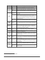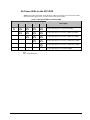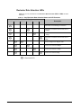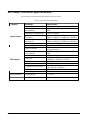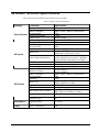
1
Cobalt Digital Inc.
9213-2OE
9214-2EO
Dual Channel Optical Converters
User Manual
9213/9214-OM
Version: 1.1
8310/8321 User Manual • (V 1.1)
Page 1
9213-2OE, 9214-2EO • Dual Channel Optical Converters User Manual
•
•
•
•
Cobalt Digital Inc. Part Number: 9213/9214-UM
Document Version: 1.1
Printed in the United States.
Last Author: CGG
The information contained in this manual is subject to change without notice or obligation.
Copyright
© 2013 Cobalt Digital Inc.. All rights reserved.
Contents of this publication may not be reproduced in any form without the written permission of
Cobalt Digital Inc.. Reproduction or reverse engineering of copyrighted software is prohibited.
Patents
This product is protected by the following US Patents: 4,205,346; 5,115,314; 5,280,346;
5,561,404; 7,034,886; 7,508,455. This product is protected by the following Canadian Patents:
2039277; 1237518; 1127289. Other patents pending.
Notice
The material in this manual is furnished for informational use only. It is subject to change without
notice and should not be construed as commitment by Cobalt Digital Inc.. Cobalt Digital Inc.
assumes no responsibility or liability for errors or inaccuracies that may appear in this manual.
Trademarks
Page 2
•
is a registered trademark of Ross Video Limited.
•
•
is a registered trademark of Cobalt Digital Inc.
All other product names and any registered and unregistered trademarks mentioned in this
manual are used for identification purposes only and remain the exclusive property of
their respective owners.
9213/9214 User Manual • (V 1.1)
Important Regulatory and Safety Notices
Before using this product and any associated equipment, refer to the “Important Safety
Instructions” listed below to avoid personnel injury and to prevent product damage.
Products may require specific equipment, and/or installation procedures to be carried out to satisfy
certain regulatory compliance requirements. Notices have been included in this publication to call
attention to these specific requirements.
Symbol Meanings
This symbol on the equipment refers you to important operating and maintenance
(servicing) instructions within the Product Manual Documentation. Failure to heed this
information may present a major risk of damage or injury to persons or equipment.
Warning — The symbol with the word “Warning” within the equipment manual
indicates a potentially hazardous situation which, if not avoided, could result in death or
serious injury.
Caution — The symbol with the word “Caution” within the equipment manual
indicates a potentially hazardous situation which, if not avoided, may result in minor or
moderate injury. It may also be used to alert against unsafe practices.
Notice — The symbol with the word “Notice” within the equipment manual indicates a
situation, which if not avoided, may result in major or minor equipment damage or a
situation which could place the equipment in a non-compliant operating state.
ESD Susceptibility — This symbol is used to alert the user that an electrical or
electronic device or assembly is susceptible to damage from an ESD event.
Important Safety Instructions
Caution — This product is intended to be a component product of an 8300 series
frame. Refer to the frame User Manual for important safety instructions regarding the
proper installation and safe operation of the frame as well as its component products.
Warning — Certain parts of this equipment namely the power supply area still
present a safety hazard, with the power switch in the OFF position. To avoid electrical
shock, disconnect all A/C power cards from the chassis’ rear appliance connectors
before servicing this area.
8310/8321 User Manual • (V 1.1)
Page 3
Warning — Service barriers within this product are intended to protect the operator
and service personnel from hazardous voltages. For continued safety, replace all
barriers after any servicing.
This product contains safety critical parts, which if incorrectly replaced may present a
risk of fire or electrical shock. Components contained with the product’s power supplies
and power supply area, are not intended to be customer serviced and should be
returned to the factory for repair. To reduce the risk of fire, replacement fuses must be
the same time and rating. Only use attachments/accessories specified by the
manufacturer.
EMC Notices
United States of America
FCC Part 15
This equipment has been tested and found to comply with the limits for a class A Digital device,
pursuant to part 15 of the FCC Rules. These limits are designed to provide reasonable protection
against harmful interference when the equipment is operated in a commercial environment. This
equipment generates, uses, and can radiate radio frequency energy and, if not installed and used in
accordance with the instruction manual, may cause harmful interference to radio communications.
Operation of this equipment in a residential area is likely to cause harmful interference in which
case the user will be required to correct the interference at his own expense.
Notice — Changes or modifications to this equipment not expressly approved by
Cobalt Digital Inc. could void the user’s authority to operate this equipment.
CANADA
This Class “A” digital apparatus complies with Canadian ICES-003.
Cet appariel numerique de la classe “A” est conforme a la norme NMB-003 du Canada.
EUROPE
This equipment is in compliance with the essential requirements and other relevant provisions of
CE Directive 93/68/EEC.
INTERNATIONAL
This equipment has been tested to CISPR 22:1997 along with amendments A1:2000 and
A2:2002, and found to comply with the limits for a Class A Digital device.
Notice — This is a Class A product. In domestic environments, this product may
cause radio interference, in which case the user may have to take adequate measures.
Page 4
9213/9214 User Manual • (V 1.1)
Important Laser Safety Measures and Notices
Before using this product and any associated equipment, refer to the sections below so as to avoid
personnel injury and to prevent product damage. For further safety information when using fiber
products, consult the following publications:
•
IEC-60825- 2, Safety of Laser Products - Part 2: Safety of Optical Fiber
Communication Systems (OFCS) (for use outside of the U.S.A.)
•
ANSI Z136.2, Safe Use of Optical Fiber Communication Systems Utilizing Laser Diode
and LED Sources (for use in the U.S.A.)
Products may require specific equipment, and /or installation procedures be carried out to satisfy
certain regulatory compliance requirements.
Caution — Before operating or servicing this product, all personnel should be familiar
with laser safety and fiber handling practices.
Safety Measures for Operation
During normal operation of this product, heed the following safety measures:
•
Do not stare at, or into, broken, or damaged, fibers.
•
Do not stare at, or into, optical connectors.
•
Only properly trained and authorized personnel should be permitted to perform laser/fiber
optic operations.
•
Ensure that appropriate labels are displayed in plain view and in close proximity to the
optical port on the protective housing/access panel of the terminal equipment.
Safety Measures for Maintenance and Servicing
Warning — Do not use optical equipment, such as a microscope or an eye loupe, to
stare at the energized fiber end. Doing so may damage your eyes.
During maintenance and servicing of this product, only properly trained and authorized personnel
shall be allowed to use optical test or diagnostic equipment.
Laser Information
CLASS 1 LASER PRODUCT
IEC 60825-1:2007
Caution — INVISIBLE LASER RADIATION WHEN OPEN. AVOID EXPOSURE TO
THE BEAM.
8310/8321 User Manual • (V 1.1)
Page 5
Maintenance/User Serviceable Parts
Routine maintenance to this Cobalt Digital Inc. product is not required. This product contains no user
serviceable parts. If the frame does not appear to be working properly, please contact Technical
Support using the numbers listed under the “Contact Us” section on the last page of this manual. All
Cobalt Digital Inc. products are covered by a generous 5-year warranty and will be repaired without
charge for materials or labor within this period. See the “Warranty and Repair Policy” section in this
manual for details.
Environmental Information
The equipment that you purchased required the extraction and use of natural resources for its
production. It may contain hazardous substances that could impact health and the environment.
To avoid the potential release of those substances into the environment and to diminish the need for the
extraction of natural resources, Cobalt Digital Inc. encourages you to use the appropriate take-back
systems. These systems will reuse or recycle most of the materials from your end-of-life equipment in
an environmentally friendly and health conscious manner.
The crossed-out wheeled bin symbol invites you to use these systems.
If you need more information on the collection, reuse, and recycling systems, please contact your local
or regional waste administration.
You can also contact Cobalt Digital Inc. for more information on the environmental performances of
our products.
Page 6
9213/9214 User Manual • (V 1.1)
8310/8321 User Manual • (V 1.1)
Page 7
Contents
Introduction
1-1
In This Chapter .......................................................................................................................1-1
A Word of Thanks ....................................................................................................1-1
Overview.................................................................................................................................1-2
Features ....................................................................................................................1-2
9213-2OE Functional Block Diagrams...................................................................................1-4
9214-2EO Functional Block Diagrams...................................................................................1-5
Documentation Terms and Conventions .................................................................................1-6
Installation
2-1
In This Chapter .......................................................................................................................2-1
Before You Begin ...................................................................................................................2-2
Static Discharge........................................................................................................2-2
Unpacking.................................................................................................................2-2
Working with Fiber Optic Connectors......................................................................2-2
Installing the 9213-2OE and 9214-2EO..................................................................................2-3
Rear Modules for the 9213-2OE and 9214-2EO ......................................................2-3
Installing a Rear Module ..........................................................................................2-3
Installing the 9213-2OE and 9214-2EO ...................................................................2-4
Cabling for the 9213-2OE and 9214-2EO ..............................................................................2-6
9213-2OE Cabling Overview ...................................................................................2-6
9214-2EO Cabling Overview ...................................................................................2-7
Software Upgrades for the 9213-2OE and 9214-2EO ............................................................2-8
User Controls
3-1
In This Chapter .......................................................................................................................3-1
Card Overview........................................................................................................................3-2
Control and Monitoring Features............................................................................................3-5
Status and Selection LEDs on the 9213-2OE and 9214-2EO ...................................3-5
Rx Power LEDs on the 9213-2OE............................................................................3-7
Reclocker Rate Selection LEDs................................................................................3-8
Menus
4-1
In This Chapter .......................................................................................................................4-1
SNMP Monitoring and Control ..............................................................................................4-2
DashBoard Menus for the 9213-2OE and 9214-2EO .............................................................4-3
Status Tab .................................................................................................................4-3
Setup Menus .............................................................................................................4-5
Alarms Menus...........................................................................................................4-6
9213-2OE/9214-2EO User Manual
Contents • i
Specifications
5-1
In This Chapter .......................................................................................................................5-1
9213-2OE Technical Specifications........................................................................................5-2
9214-2EO Technical Specifications........................................................................................5-3
Service Information
6-1
In This Chapter .......................................................................................................................6-1
Troubleshooting Checklist ......................................................................................................6-2
Bootload Button........................................................................................................6-2
Warranty and Repair Policy....................................................................................................6-3
ii • Contents
9213-2OE/9214-2EO User Manual
Introduction
In This Chapter
This chapter contains the following sections:
•
Overview
•
9213-2OE Functional Block Diagrams
•
9214-2EO Functional Block Diagrams
•
Documentation Terms and Conventions
A Word of Thanks
Congratulations on choosing an openGear 9213-2OE and 9214-2EO Dual Channel Optical
Converters . ). The Cobalt Digital Inc. openGearTM line includes video decoders and encoders, audio
embedders and de-embedders, distribution amplifiers, format converters, and much more. Cobalt
Digital Inc. openGearTM modular conversion gear will meet your signal conversion needs now, and well
into the future.
Should you have a question pertaining to the installation or operation of your 9213-2OE and/or 92142EO, please contact us at the numbers listed on the back cover of this manual. Our technical support
staff is always available for consultation, training, or service.
9213-2OE, 9214-2EO User Manual
Introduction • 1-1
Overview
The 9213-2OE and 9214-2EO provide the ability to transport digital video baseband signals over a
fiber optic link, allowing for longer transport distances. SDI outputs are reclocked providing
excellent jitter and return loss specifications. Both cards support serial digital data rates from
270Mbps up to 2.98Gbps (1080p). LED indicators at the front of the card identify the presence of
incoming video and the identified signal data rates for each channel independently. The 9213-2OE
and 9214-2EO are fully hot swappable with all active components on the front removable module.
No active components are installed on the rear module. This design greatly reduces down time
eliminating any need for users to access the back of the rack frame.
The 9213-2OE is a fiber optic receiver to serial digital SDI converter capable of equalizing all
common serial digital signals. Each channel of the 9213-2OE equalizes the incoming SDI signal.
Both channels provide 3 outputs each.
The 9214-2EO is a serial digital SDI to fiber optic converter capable of equalizing and reclocking
all common serial digital signals. Each channel of the 9214-2EO equalizes the incoming SDI
signal, reclocks the signal with automatic rate detection for all popular data rates. Each channel is
fully independent and can run at different data rates.
Features
The following features are standard for the 9213-2OE and 9214-2EO:
1-2 • Introduction
•
Supports a wide variety of standards (SD, HD, and 3G SDI)
•
Conforms to SMPTE 424M, SMPTE 292M, and SMPTE 259M-C
•
Future proofed design 3Gbps (1080p)
•
Supports single-mode fiber
•
Hot-swappable from front of frame with no external connect/reconnect required
•
9213-2OE provides two fiber optic inputs and six SDI outputs using a Full Rear Module
•
9214-2EO provides two SDI inputs, two fiber optic outputs, and four SDI outputs using a
Full Rear Module
•
Optical input range 1210nm to 1610nm
•
Optical input sensitivity -19dBm
•
LC/UPC optical connections
•
Reclocking on all outputs at 270Mbps, 1.483Gbps, 1.485Gbps, 2.967Gbps, and
2.970Gbps
•
Automatic detection of incoming data rate
•
LED indicators for signal presence and data rate
•
Reports status and configuration remotely via the DashBoard Control System™
•
Fits 20-slot frame
9213-2OE, 9214-2EO User Manual
•
High density with 20 cards per frame in a 20-slot frame using Split Rear Modules
•
Fully compliant with openGear specifications
•
5-year transferable warranty
9213-2OE, 9214-2EO User Manual
Introduction • 1-3
9213-2OE Functional Block Diagrams
This section provides a functional block diagrams that outlines the signal flow of the 9213-2OE.
Figure 1.1 9213-2OE with a Full Rear Module — Simplified Block Diagram
Figure 1.2 9213-2OE with a Split Rear Module — Simplified Block Diagram
1-4 • Introduction
9213-2OE, 9214-2EO User Manual
9214-2EO Functional Block Diagrams
This section provides a functional block diagrams that outlines the workflow of the 9214-2EO.
Figure 1.3 9214-2EO Full Rear Module — Simplified Block Diagram
Figure 1.4 9214-2EO Split Rear Module — Simplified Block Diagram
9213-2OE, 9214-2EO User Manual
Introduction • 1-5
Documentation Terms and Conventions
The following terms and conventions are used throughout this manual:
1-6 • Introduction
•
“Frame” refers to the frame that houses the 9213-2OE and 9214-2EO.
•
All references to the 8310 and 8321 also include the 8310-C and 8321-C versions
(respectively) with the cooling fan option.
•
“Operator” and “User” refer to the person who uses 9213-2OE and 9214-2EO.
•
“Board”, and “Card” refer to openGear terminal devices within openGear frames,
including all components and switches.
•
“System” and “Video system” refer to the mix of interconnected production and terminal
equipment in your environment.
•
“-line mode ” refers to broadcast situations using NTSC composite (analog) signal
reference inputs.
•
“-line mode ” refers to broadcast situations using PAL-B composite (analog) signal
reference inputs.
•
“PAL” refers to PAL-B and PAL-G unless otherwise stated.
•
The “Operating Tips” and “Note” boxes are used throughout this manual to provide
additional user information.
9213-2OE, 9214-2EO User Manual
Installation
In This Chapter
This chapter provides instructions for installing the Rear Module(s) for the 9213-2OE and 92142EO, installing the cards into the frame, cabling details, and updating the software.
The following topics are discussed:
•
Before You Begin
•
Installing the 9213-2OE and 9214-2EO
•
Cabling for the 9213-2OE and 9214-2EO
•
Software Upgrades for the 9213-2OE and 9214-2EO
9213-2OE, 9214-2EO User Manual
Installation and Setup • 2-1
Before You Begin
Static Discharge
Throughout this chapter, please heed the following cautionary note:
ESD Susceptibility — Static discharge can cause serious damage to sensitive
semiconductor devices. Avoid handling circuit boards in high static environments such as
carpeted areas and when synthetic fiber clothing is worn. Always exercise proper grounding
precautions when working on circuit boards and related equipment.
Unpacking
Unpack each 9213-2OE and 9214-2EO you received from the shipping container and ensure that
all items are included. If any items are missing or damaged, contact your sales representative or
Cobalt Digital Inc. directly.
Working with Fiber Optic Connectors
Keep the following in mind when working with fiber optic connectors:
•
Every time you are required to insert a connector into a device or mating sleeve, you must
clean the connector. All exposed surfaces of the ceramic ferrule must be clean. Follow
your facility practices of cleaning fiber optic connectors.
•
Connectors must always be inserted into a device or have a dust cap on. Refer to Figure
2.1 for dust cap locations.
•
A poor optical connection is often similar to a poor electrical connection. Try removing
the connector, cleaning, and re-inserting the connector. A bad connection can result in
experiencing instability of signal, high loss, or a noisy signal.
Figure 2.1 Card Connectors with Dust Caps Installed
2-2 • Installation and Setup
9213-2OE, 9214-2EO User Manual
Installing the 9213-2OE and 9214-2EO
This section outlines how to install a Rear Module in an 8321 series frame. However, the specific
Rear Module you need to install depends on your application.
Caution — Never attempt to look down the barrel of a connected fiber or device
transmitting an optical signal. The transmitted light is not in the visible spectrum and
may cause permanent eye damage. Turn off all laser sources before disconnecting
devices.
Rear Modules for the 9213-2OE and 9214-2EO
The Rear Module for the 9213-2OE and 9214-2EO depends on the openGear frame you are
installing the card into.
•
9213-2OE — The RM20-9213-B Full Rear Module or the RM20-9213-B/S Split Rear
Module can be used. Note that the available cable designations differ between the type of
module used. Refer to the section Error! Reference source not found. for details.
•
9214-2EO — The RM20-9214-B Full Rear Module or the RM20-9214-B/S Split Rear
Module can be used. Note that the available cable designations differ between the type of
module used. Refer to the section Error! Reference source not found. for details.
Installing a Rear Module
If the Rear Module is already installed, proceed to the section “Installing the 9213-2OE and
9214-2EO”.
Use the following procedure to install a Rear Module in your 8321 series frame:
1. Locate the card frame slots on the rear of the frame.
2. Remove the Blank Plate from the slot you have chosen for the 9213-2OE and 9214-2EO
installation. If there is no Blank Plate installed, proceed to the next step.
3. Remove the dust caps from the Fiber ports on the Rear Module that faces the interior of
the frame. Refer to Figure 2.1 and Figure 2.2 for dust cap locations.
Figure 2.2 Card Connectors Connectors with Dust Caps Removed
9213-2OE, 9214-2EO User Manual
Installation and Setup • 2-3
4. Install the bottom of the Rear Module in the Module Seating Slot at the base of the
frame’s back plane.
5. Align the top hole of the Rear Module with the screw on the top-edge of the frame back plane.
6. Using a Phillips drive and the supplied screw, fasten the Rear Module to the back plane of
the frame. Do not over tighten.
7. Ensure proper frame cooling and ventilation by having all rear frame slots covered with
Rear Modules or Blank Plates.
This completes the procedure for installing a Rear Module in your 8321 series frame.
Installing the 9213-2OE and 9214-2EO
Use the following procedure to install the 9213-2OE or 9214-2EO in an 8321 series frame:
1. Locate the Rear Module you installed in the procedure “Installing a Rear Module”.
2. Ensure that the Rear Module is one of the required rear modules for the 9213-2OE or
9214-2EO. You must use either a Full Rear Module or a Split Rear Module.
3. Remove the dust caps from the Fiber 1 and Fiber 2 port connectors on the card end.
•
Refer to Figure 2.1 and Figure 2.3 for connector location.
•
Refer to the section “Important Laser Safety Measures and Notices”at the
beginning of this manual for safety information when handling fiber optic
components.
Figure 2.3 Card Connectors with Dust Caps Removed
4. Ensure that the exposed surface of the ceramic ferrule of the connectors is clean. Refer to
the section “Working with Fiber Optic Connectors” for cleaning tips.
5. Hold the card by the edges and carefully align the card-edges with the slots in the frame.
6. Fully insert the card into the frame until the rear connection plus is properly seated in the
Rear Module. You will feel a click when the card mates onto the rear module.
7. Affix the supplied Rear Module Label, as per the included instructions, to the BNC area
of the Rear Module.
2-4 • Installation and Setup
9213-2OE, 9214-2EO User Manual
8. Remove the dust cap from the Fiber 1 port (the topmost fiber optic port) on the Rear
Module that faces the exterior of the frame. This is the port that you will insert your Fiber
A optic cable into.
9. Remove the dust cap from the Fiber 2 port (the bottom fiber optic port) on the Rear
Module that faces the exterior of the frame. This is the port that you will insert your Fiber
B optic cable into.
10. Ensure the ceramic ferrule of each connector is clean.
11. Cable your rear module as outlined in the section “Cabling for the 9213-2OE and
9214-2EO”.
This completes the procedure for installing the 9213-2OE or 9214-2EO in an 8321 series frame.
9213-2OE, 9214-2EO User Manual
Installation and Setup • 2-5
Cabling for the 9213-2OE and 9214-2EO
This section provides information for connecting cables to the installed Rear Modules on a 20-slot
frame. Connect the input and output cables according to the following sections.
The optical connector used to mate the card to the rear module is designed for blind mate optical
connections. All fiber interfaces are single mode fibers.
Notice — Every time you are required to insert a connector into a device, or mating
sleeve, you must clean the connector. All exposed surfaces of the ceramic ferrule must
be clean. Follow your facility practices of cleaning fiber optic connectors.
Connectors must always be inserted into a device or have a dust cap on.
9213-2OE Cabling Overview
In a 20-slot frame, the 9213-2OE is used with the following Rear Modules:
•
RM20-9213-B Full Rear Module — Each 9213-2OE occupies two slots and provides two
optical inputs, and six SDI outputs. Figure 2.5
•
RM20-9213-B/S Split Rear Module — Each 9213-2OE occupies one slot and provides
two optical inputs, and three SDI outputs. Figure 2.6
Figure 2.5 Cable Connections for the RM209213-B Rear Module
2-6 • Installation and Setup
Figure 2.6 Cable Connections for the RM209213-B/S Rear Module
9213-2OE, 9214-2EO User Manual
9214-2EO Cabling Overview
In a 20-slot frame, the 9214-2EO is used with the following Rear Modules:
•
RM20-9214-B Full Rear Module — Each 9214-2EO occupies two slots and provides two
optical outputs, two SDI inputs, and four SDI outputs. Figure 2.7
•
RM20-9214-B/S Split Rear Module — Each 9214-2EO occupies one slot and provides
two optical outputs, two SDI inputs, and one SDI output. Figure 2.8
Figure 2.7 Cable Connections for the RM209214-B Rear Module
9213-2OE, 9214-2EO User Manual
Figure 2.8 Cable Connections for the RM209214-B/S Rear Module
Installation and Setup • 2-7
Software Upgrades for the 9213-2OE and 9214-2EO
This section provides instructions for installing a license key and upgrading the software for your
9213-2OE and 9214-2EO using the DashBoard Control System™.
Use the following procedure to upload software to the 9213-2OE and 9214-2EO:
1. Contact Technical Support for the latest software version file.
2. In DashBoard, display the Device tab of the 9213-2OE and 9214-2EO by double-clicking
its status indicator in the Basic Tree View.
3. From the Device tab, click Upload to display the Select File for upload dialog box.
4. Navigate to the *.bin upload file you wish to upload. DashBoard automatically selects the
last directory that you loaded from.
5. Click Open to display a confirmation dialog box. This dialog box displays the selected
upload file name, type, size, and the file creation date.
6. From the Confirmation dialog box, select one of the following:
•
Cancel — Select this option to cancel the upload of the file and return to the Device
View.
•
Continue — Select this option to upload the file. While uploading, an Uploading
Progress dialog box opens.
Important — Pressing the Cancel button while uploading will leave the card in an invalid
state. Do not click Cancel unless the uploading progress has stopped completely for 60 seconds
or more. If upload fails, repeat the upload process from DashBoard. If the upload process fails
again, refer to the section “Bootload Button” on page 6-2.
7. Monitor the upgrade progress bar displayed in DashBoard while the software is upgraded
on your 9213-2OE and 9214-2EO.
8. To complete the upgrade process, you must reboot the card as follows:
•
The reboot process takes up to 30 seconds.
Note — The communications processor of the 9213-2OE and 9214-2EO requires
approximately 30 seconds to re-start and re-establish network communications.
•
The 9213-2OE and 9214-2EO automatically saves all your settings before starting
the reboot process.
•
The reboot process is complete once the status indicators for the Card State and
Connection return to their previous status.
This completes the procedure to upload software to the 9213-2OE and 9214-2EO.
2-8 • Installation and Setup
9213-2OE, 9214-2EO User Manual
User Controls
In This Chapter
This chapter provides a general overview of the user controls available on the 9213-2OE and
9214-2EO.
The following topics are discussed:
•
Card Overview
•
Control and Monitoring Features
9213-2OE, 9214-2EO User Manual
User Controls • 3-1
Card Overview
This section provides a general overview of the 9213-2OE and 9214-2EO components. For
information on the LEDs available on the card-edge, refer to the section “Control and
Monitoring Features”.
Figure 3.1 9213-2OE and 9214-2EO — Components
1) Rx Power LEDs - Channel A
5) Select Switch - Channel A (SW1)
9) Select Switch - Channel B (SW2)
2) Card Control (JP1)
6) Rx Power LEDs - Channel B
10) Bootload Button (SW3 )
3) Loss of Signal - Channel A (JP2)
7) Loss of Signal - Channel B (JP4)
11) Fiber Optic Connector
4) Bypass EQ Mode - Channel A (JP3)
8) Bypass EQ Mode - Channel B (JP5)
1. Rx Power LEDs - Channel A
In this area of the 9213-2OE, five LEDs are available to indicate the input optical power as
detected by the optical module for Channel A. Refer to the section “Rx Power LEDs on the 92132OE” for details.
2. Card Control (JP1)
Use JP1 to select whether the card is remotely configured (for example, via DashBoard or
SNMP). You can select one of the following options:
•
REMOTE — This option enables the remote configuration. All parameters may be
configured remotely. Data rate selection can also be configured locally using SW1,
however, the jumper settings are ignored. Refer to the section “DashBoard Menus for the
9213-2OE and 9214-2EO” on page 4-3 for information on the available DashBoard
menus.
•
LOCAL — This option disables the remote configuration. The card can only be
configured using the card-edge controls. This option is useful to lock out remote
configuration changes. This is the default setting.
Note — The card status and configuration can still be monitored remotely when JP1 is
set to LOCAL.
3. Loss of Signal - Channel A (JP2)
Use JP2 to determine the card behavior on a loss of input on Channel A. Note that the JP2 setting
is only used when JP1 is set to LOCAL. You can select one of the following options:
3-2 • User Controls
9213-2OE, 9214-2EO User Manual
•
MUTE — This option mutes the card outputs when the input equalizer is unable to detect
a valid input signal, or when the reclocker is unable to lock to the input.
•
NO MUTE — This option does not mute the card outputs on loss of input or lock. This is
the default setting.
4. Bypass EQ Mode - Channel A (JP3)
Use JP3 to determine the equalizer behavior when the Reclocker Rate is set to BYPASS (using
SW1) for Channel A. This jumper is only implemented for the 9214-2EO. You can select one of
the following:
•
EQ — This option enables the input cable equalizer.
•
NO EQ — This option disables the equalizer when the Reclocker Rate is set to BYPASS.
This option allows the card to pass signals that are outside the response band of the
equalizer reclocking, such as 143MHz. This is useful for non-SMPTE data rates.
5. Select Switch - Channel A (SW1)
Use SW1 to set the reclocking rate of the card for Channel A. Pressing SW1 cycles through the
following options:
•
AUTO — This option enables automatic rate detection on the card. It will automatically
lock to input at any supported data rate (270Mbps, 1.5Gbps, or 3Gbps).
•
BYPASS — This option enables the card to pass any data rate without reclocking. The
output is set to the HD slew rate except when the input is a valid SD data rate (270Mbps).
•
270M — This option configures the card to reclock at a rate of 270Mbps (SD).
•
1.5G — This configures the card to reclock at a rate of 1.5Gbps (HD).
•
3G — This configures the card to reclock at a rate of 3Gbps (HD).
6. Rx Power LEDs - Channel B
In this area of the 9213-2OE, five LEDs are available to indicate the power consumption of the
optical module for Channel B. Refer to the section “Rx Power LEDs on the 9213-2OE” for
details.
7. Loss of Signal - Channel B (JP4)
Use JP4 to determine the card behavior on a loss of input on Channel B. Same options as for
Channel A.
8. Bypass EQ Mode - Channel B (JP5)
Use JP5 to determine the card behavior on a loss of input on Channel B. Note that the JP5 setting
is only used when JP1 is set to LOCAL. Same options as for Channel A. This jumper is only
implemented for the 9214-2EO.
9. Select Switch - Channel B (SW2)
Use SW2 to set the reclocking rate of the card for Channel B. Same options as for Channel A.
9213-2OE, 9214-2EO User Manual
User Controls • 3-3
10. Bootload Button (SW3)
JP3 is used for factory service in the unlikely event of a complete card failure. The Bootload
process is further described in the section “Bootload Button” on page 6-2.
11. Fiber Optic Connector
The 9213-2OE and 9214-2EO use a blind mate LC/UPC connector to interface with the Rear
Modules. The rear module remains passive, while allowing for the FSR-6601 or FST-6602 to be
replaced without the need to remove any connected BNC or fiber optic cables. The blind mate
connector is connected to the optical module via a single mode LC/UPC pigtail.
The fiber optic connector for the card includes a dust cap. The dust cap must stay on at all times
when the card is not installed in a frame. Ensure to keep the fibers end face clean and use the caps
to protect the fiber from scratches and collecting dust. Refer to the section “Important Laser
Safety Measures and Notices” at the beginning of this manual for safety information.
3-4 • User Controls
9213-2OE, 9214-2EO User Manual
Control and Monitoring Features
This section provides information on the jumpers, buttons and LEDs for the 9213-2OE and 92142EO. Refer to Figure 3.2 for the location of the LEDs. For information on the Rx Power LEDs,
refer to the section “Card Overview”.
Figure 3.2 9213-2OE and 9214-2EO Card-edge Controls
Status and Selection LEDs on the 9213-2OE and 9214-2EO
The front-edge of the 9213-2OE and 9214-2EO have LED indicators for alarms, and
communication activity. Basic LED displays and descriptions are provided Table 3.1.
Table 3.1 LEDs on the 9213-2OE and 9214-2EO
LED
PWR
PWR
Color
Display and Description
Green
When lit green, this LED indicates that the card is functioning
normal and that no anomalies have been detected.
Flashing Green
When flashing green, this LED indicates that the bootloader is
currently running.
Yellow
When lit yellow, this LED indicates that the CPU is booting.
Red
When lit red, this LED indicates that the card is powering on or
there is a fault condition.
9213-2OE, 9214-2EO User Manual
User Controls • 3-5
LED
Color
Display and Description
Off
When unlit, this LED indicates a lack of power to the card.
Green
When lit, this LED indicates that a valid input signal is present.
Red
When lit red, this LED indicates a valid input signal is not present.
Green
When lit green, this LED indicates that the reclocker is locked to the
input signal.
Red
When lit red, this LED indicates that the reclocker is unable to lock
to the input. This typically indicates that the input data rate is
different from the configured reclocking rate, or that the input is an
unsupported data rate.
Off
When unlit, this LED indicates that the reclockers is set to Bypass.
AUTO
Yellow
When lit, this LED indicates that the reclocker is configured to lock
to any supported input data rate, using an automatic rate detection
scheme.
MANUAL
Yellow
When lit, this LED indicates that the reclocker is configured to a
fixed data rate or to Bypass. When configured to a fixed data rate,
automatic data rate detection is disabled.
BYPASS
Yellow
When lit, this LED indicates that the reclocker is manually
configured to Bypass. The card output is not reclocked.
OTHER
Yellow
This LED is not implemented.
270
Yellow
When lit, this LED indicates that the reclocker is set to a fixed rate
of 270Mbps (SD) or is configured in Auto mode and is locked to a
270Mbps SD signal.
1G5
Yellow
When lit, this LED indicates that the reclocker is set to a fixed rate
of 1.5Gbps (HD), or is configured in Auto mode and is locked to a
1.5Gbps HD signal.
3G
Yellow
When lit, this LED indicates that the reclocker is set to a fixed rate
of 3Gbps (HD), or is configured in Auto mode and is locked to a
3Gbps HD signal.
Green
When lit green, this LED indicates that the Fiber Tx signal is
functioning normal and that no anomalies have been detected.
Red
hen lit red, this LED indicates that there is a fault condition with
he Fiber Tx signal.
OK/ERROR
LOCK
FIBER Tx
*
OK/ERROR
*
This LED only applies to the 9214-2EO.
3-6 • User Controls
9213-2OE, 9214-2EO User Manual
Rx Power LEDs on the 9213-2OE
Table 3.2 provides information on the Rx Power LEDs located on the 9213-2OE. These LEDs
indicate the input optical power as reported by the card optical module.
-6
Table 3.2 Rx Power LEDs on the 9213-2OE
Rx Power LEDs
Description
-9
-12
-15
-18
The input optical power is greater than -6dBm
The input optical power is between -6dBm and -9dBm
The input optical power is between -9dBm and -12dBm
The input optical power is between -12dBm and -15dBm
The input optical power is between -15dBm and -18dBm
The input optical power is less than -18dBm
= Illuminated LED
9213-2OE, 9214-2EO User Manual
User Controls • 3-7
Reclocker Rate Selection LEDs
Table 3.3 provides information on the Reclocker Rate Selections (SW1 or SW2) and LED
functions.
AUTO
Table 3.3 Card Reclocker Rate Selection Button and LED Functions
Date Rate LED Displays
Description
MANUAL BYPASS 270M
1G5
3G
Auto mode, card searching for valid rate
Auto mode, card detects and reclocks rate of
270Mbps
Auto mode, card detects and reclocks rate of
1.5Gbps
Auto mode, card detects and reclocks rate of
3Gbps
Card is configured for Bypass mode
Card is set to reclock 270Mbps
Card is set to reclock 1.5Gbps
Card is set to reclock 3Gbps
= Illuminated LED
3-8 • User Controls
9213-2OE, 9214-2EO User Manual
Menus
In This Chapter
This chapter provides a summary of the menus available for the 9213-2OE and 9214-2EO.
The following topics are discussed:
•
SNMP Monitoring and Control
•
DashBoard Menus for the 9213-2OE and 9214-2EO
9213-2OE, 9214-2EO User Manual
Menus • 4-1
SNMP Monitoring and Control
The Network Controller Card in an 8321 series frame provides optional support for remote
monitoring of your frame and using the Simple Network Management Protocol (SNMP), which is
compatible with many third-party monitoring and control tools.
Refer to your 9213-2OE and 9214-2EO Management Information Base (MIB) files for a
breakdown of SNMP controls on the cards. Refer to the MFC-8300 Series User Manual for
additional information on SNMP Monitoring and Control.
4-2 • Menus
9213-2OE, 9214-2EO User Manual
DashBoard Menus for the 9213-2OE and 9214-2EO
The DashBoard Control System™ enables you to monitor and control openGear frames and cards
from a computer. DashBoard communicates with other cards in an 8321 series frame through the
Network Controller Card. This section briefly summarizes the menus, items, and parameters
available from the DashBoard Control System™ for the 9213-2OE and 9214-2EO. Default values
are indicated with an asterisk (*).
Status Tab
Table 4.1 summarizes the Status tab parameters available in DashBoard. The Status tabs provide
read-only information such as software revision issue, hardware status, and power consumption.
Table 4.1. Status Menu Functions
Menu
Item
Parameters
Description
9213-2OE or
Product
9214-2EO
Product
(Readonly)
Supplier
Cobalt Digital Inc.
Board Rev
##
Board S/N
######
Indicates the card serial number
Software Rev
##.##
Indicates the software version
OK
FPGA load invalid
Incomp I/O Module
Current out of spec
Internal Error
Hardware
(Readonly)
HW Status
SFP Temp Low
SFP Temp High
Indicates the status of the hardware
including the SFP module. Some
messages displayed are dependent on
the settings in the Alarms Enable tab.
SFP Power High
SFP Power Low
SFP Tx Fault
SFP Not Detected
Voltage (mV)
#
Supply Voltage
Current (mA)
#
Current consumption of card
9213-2OE, 9214-2EO User Manual
Menus • 4-3
Menu
Item
Parameters
Description
14.4
Indicates a Full Rear Module is
installed
15.4
Indicates a Split Rear Module is
installed
Rear Module
Hardware
(Readonly)
Optical Module
Temperature (C)
#
Optical Tx
Wavelength (nm
#
Available for the 9214-2EO only.
CPU Headroom
#
Processing power available
RAM Available
#/##
On-board processing memory available
Uptime (h)
#
Displays the number of hours since the
last reboot of the card
Configuration Bank
#
Storage count
OK
No Input
Reclocker unlocked
SFP Hi Temp
Channel Status
SFP Lo Temp
Indicates when the channel is
functioning normally or if anomalies are
detected
SFP Hi Power
SFP Tx Fault
SFP Not Detected
Signal
(Readonly)
No Signal
SDI Input
Signal Present
(BNC)
Indicates when the SDI Input is present
or if anomalies are detected
Signal Present
(Fiber)
Locked - #
Undefined Rate
Bypass Reclocking
SDI Output
No Signal
Indicates the status of the SDI Output
No Signal (muted)
Unlocked
Unlocked (muted)
4-4 • Menus
9213-2OE, 9214-2EO User Manual
Menu
Item
Parameters
Description
OK
No Signal
Temp High
Temp Low
Rx Power High
Optical Module
Status
Tx Power High
Indicates the status of the card Optical
Module
Rx Power Low
Signal
(Readonly)
Tx Power Low
Tx Fault
Tx Disabled
Not Detected
Optical Rx Power
(dBm)
#
Indicates the power consumption of the
Optical Module. This value is accurate
to ±3dB. ( 9213-2OE only)
Optical Tx Power
(dBm)
#
Indicates the power consumption of the
Optical Module. ( 9214-2EO only)
Setup Menus
Table 4.2 summarizes the Setup Menu options available in DashBoard.
Table 4.2 Setup Menu Items
Menu
Item
Reclock Rate
Setup
Parameters
Description
Auto
The card automatically detects the
incoming data rate
Bypass
The card does not reclock the input
270 Mb/s
The reclocker is set to 270Mbps
1.5 Gb/s
The reclocker is set to 1.5Gbps
3 Gb/s
The reclocker is set to 3Gbps
Checkbox is
selected*
The equalizer is always enabled
Checkbox is
unselected
The equalizer is disabled when the
card is in Bypass Mode
Enable Equalizer
Mute on Loss of
Input
9213-2OE, 9214-2EO User Manual
Checkbox is
selected*
The output is muted on loss of input
Checkbox is
unselected
The output is not muted on loss of
input
Menus • 4-5
Menu
Item
Edit Permission
Parameters
Unlocked*
All configurable menu options are
editable
Locked
All configuration menu options,
except this one, are locked an are
read-only
Local Only
JP1 is set to LOCAL and all
configuration parameters, including
this one, are locked and read-only
Setup
Factory Defaults
Reset
Description
Reset
Resets all the settings
Alarms Menus
Table 4.3 summarizes the Alarms Menu options available in DashBoard.
Table 4.3 Alarms Menu Items
Menu
Item
Alarm on Abnormal
Power
Optical
Module
Alarms
Alarm on Abnormal
Temperature
Channel
#
4-6 • Menus
Alarm on Loss of
Input
Parameters
Description
Checkbox is
selected
HW Status field reports when the
power consumption of the SFP
module is not in range (high/low)
Checkbox is
unselected
Disables this alarm
Checkbox is
selected
HW Status field reports when the
temperature of the SFP module is not
in range (high/low)
Checkbox is
unselected
Disables this alarm
Checkbox is
selected
Signal Status field reports a loss of
input for the specified channel
Checkbox is
unselected
Disables this alarm
9213-2OE, 9214-2EO User Manual
Specifications
In This Chapter
This chapter includes the technical specifications for the 9213-2OE and 9214-2EO. Note that
specifications are subject to change without notice.
The following topics are discussed:
•
9213-2OE Technical Specifications
•
9214-2EO Technical Specifications
9213-2OE, 9214-2EO User Manual
Specifications • 5-1
9213-2OE Technical Specifications
This section provides the technical specifications for the 9213-2OE.
Table 5.1 9213-2OE Technical Specifications
Category
Parameter
Number of Inputs
SMPTE Standards
Accommodated
Operating Wavelength Range
Input Power Operating Range
(Color Bars)
Input Power Operating Range
(Pathological)
Receiver Overload
Connector Type
Specification
2
Overshoot
Connector Type
SMPTE 259M-C, SMPTE 292M, SMPTE
424M
1210nm to 1600nm
-3dBm to -18dBm @ 2.97Gbps
-3dBm to -19dBm @ 270Mbps and 1.485Gbps
-3dBm to -17dBm @ 2.97Gbps
-3dBm to -18dBm @ 270Mbps and 1.485Gbps
At values above -3dB
Single Mode, LC/UPC
Full Rear Module: 6
Split Rear Module: 3
SMPTE 259M-C, SMPTE 292M, SMPTE
424M
75ohm
>15dB to 1.485GHz
>10dB from 1.485GHz to 2.97GHz
800mV ±10%
0V ±50mV
700ps. Typical (270Mbps)
120ps. Typical (1.485Gbps)
<10%
BNC
Environmental
Operating Range
0°C to 40°C
Power
Power Consumption
<5W
Optical Inputs
Number of Outputs
SMPTE Standards
Accommodated
Impedance
SDI Outputs
Return Loss
Signal Level
DC Offset
Rise and Fall Time (20-80%)
5-2 • Specifications
9213-2OE, 9214-2EO User Manual
9214-2EO Technical Specifications
This section provides the technical specifications for the 9214-2EO.
Table 2. 9214-2EO Technical Specifications
Category
Optical Outputs
Parameter
Number of Outputs
SMPTE Standards
Accommodated
Nominal Wavelength
Output Power
Connector Type
Number of Inputs
SMPTE Standards
Accommodated
Impedance
Return Loss
SDI Inputs
Cable Length with Equalizer
DC Offset
Signal Level
Connector Type
Number of Outputs
SMPTE Standards
Accommodated
Impedance
Return Loss
SDI Outputs
Signal Level
DC Offset
Rise and Fall Time (20-80%)
Specification
2
SMPTE 259M-C, SMPTE 292M, SMPTE
424M
1310nm
-7dBm to -2dBm
Single Mode, LC/UPC
2
SMPTE 259M-C, SMPTE 292M, SMPTE
424M
75ohm terminating
>15dB to 1.485GHz
>10dB from 1.485GHz to 2.97GHz
> 300m of Belden 1694A cable @ 270Mbps
> 120m of Belden 1694A cable @ 1.485Gbps
> 80m of Belden 1694A cable @ 2.97Gbps
±0.5V maximum
Max. 1V p-p (0m cable length)
BNC
Full Rear Module: 4
Split Rear Module: 1
SMPTE 259M-C, SMPTE 292M, SMPTE
424M
75ohm
>15dB to 1.485GHz
>10dB 1.485GHz to 2.97GHz
800mV ±10%
0V ±50mV
700ps. Typical (270Mbps)
120ps. Typical (1.485Gbps, 2.97Gbps)
Overshoot
<10%
Connector Type
BNC
Environment
Operating Range
0°C to 40°C
Power
Power Consumption
<5W
9213-2OE, 9214-2EO User Manual
Specifications • 5-3
Service Information
In This Chapter
This chapter contains the following sections:
•
Troubleshooting Checklist
•
Warranty and Repair Policy
9213-2OE, 9214-2EO User Manual
Service Information • 8-1
Troubleshooting Checklist
Routine maintenance to this product is not required. In the event of problems with your 9213-2OE or
9214-2EO, the following basic troubleshooting checklist may help identify the source of the problem. If
the module still does not appear to be working properly after checking all possible causes, please
contact Technical Support at the numbers listed under the “Contact Us” section at the end of this
manual.
1.
Visual Review – Performing a quick visual check may reveal many problems, such
as connectors not properly seated or loose cables. Check the module, the frame, and
any associated peripheral equipment for signs of trouble.
2.
Power Check – Check the power indicator LED on the distribution frame front panel
for the presence of power. If the power LED is not illuminated, verify that the power
cable is connected to a power source and that power is available at the power main.
Confirm that the power supplies are fully seated in their slots. If the power LED is
still not illuminated, replace the power supply with one that is verified to work.
3.
Reseat the Card in the Frame – Eject the card and reinsert it in the frame.
4.
Check Control Settings – Refer to the Installation and Operation sections of the
manual and verify all user-adjustable component settings.
5.
Input Signal Status – Verify that source equipment is operating correctly and that a
valid signal is being supplied.
6.
Output Signal Path – Verify that destination equipment is operating correctly and
receiving a valid signal.
7.
Card Exchange – Exchanging a suspect card with a card that is known to be
working correctly is an efficient method for localizing problems to individual cards.
Bootload Button
In the unlikely event of a complete card failure, you may be instructed by a Technical Support
specialist to perform a complete software reload on the 9213-2OE or 9214-2EO.
Use the following procedure to perform a software reload on the 9213-2OE or 9214-2EO:
1.
Eject the card.
2.
Press and hold the Bootload button, while re-inserting the card into the frame.
3.
Release the button.
The PWR LED will flash GREEN while the card is waiting for a new software load.
If a new software load is not sent to the card within 60 seconds, the card will attempt to
restart with the last operational software load.
Software can be uploaded to the 9213-2OE or 9214-2EO via DashBoard. Refer to your DashBoard
Control System Software User Manual for further instructions.
8-2 • Service Information
9213-2OE, 9214-2EO User Manual
Warranty and Repair Policy
Cobalt Digital Inc. Limited Warranty
This product is warranted to be free from defects in material and workmanship for a period of five (5)
years from the date of shipment to the original purchaser, except that 4000, 5000, 6000, 8000 series
power supplies, and Dolby® modules (where applicable) are warranted to be free from defects in
material and workmanship for a period of one (1) year.
Cobalt Digital Inc.'s (“Cobalt”) sole obligation under this warranty shall be limited to, at its option, (i)
the repair or (ii) replacement of the product, and the determination of whether a defect is covered under
this limited warranty shall be made at the sole discretion of Cobalt.
This limited warranty applies only to the original end-purchaser of the product, and is not assignable or
transferrable therefrom. This warranty is limited to defects in material and workmanship, and shall not
apply to acts of God, accidents, or negligence on behalf of the purchaser, and shall be voided upon the
misuse, abuse, alteration, or modification of the product. Only Cobalt authorized factory
representatives are authorized to make repairs to the product, and any unauthorized attempt to repair
this product shall immediately void the warranty. Please contact Cobalt Technical Support for more
information.
To facilitate the resolution of warranty related issues, Cobalt recommends registering the product by
completing and returning a product registration form. In the event of a warrantable defect, the
purchaser shall notify Cobalt with a description of the problem, and Cobalt shall provide the purchaser
with a Return Material Authorization (“RMA”). For return, defective products should be double boxed,
and sufficiently protected, in the original packaging, or equivalent, and shipped to the Cobalt Factory
Service Center, postage prepaid and insured for the purchase price. The purchaser should include the
RMA number, description of the problem encountered, date purchased, name of dealer purchased from,
and serial number with the shipment.
Cobalt Digital Inc. Factory Service Center
2406 E. University Avenue
Office: (217) 344-1243
Urbana, IL 61802 USA
Fax:
www.cobaltdigital.com
Email: [email protected]
(217) 344-1245
THIS LIMITED WARRANTY IS EXPRESSLY IN LIEU OF ALL OTHER WARRANTIES
EXPRESSED OR IMPLIED, INCLUDING THE WARRANTIES OF MERCHANTABILITY AND
FITNESS FOR A PARTICULAR PURPOSE AND OF ALL OTHER OBLIGATIONS OR
LIABILITIES ON COBALT'S PART. ANY SOFTWARE PROVIDED WITH, OR FOR USE WITH,
THE PRODUCT IS PROVIDED “AS IS.” THE BUYER OF THE PRODUCT ACKNOWLEDGES
THAT NO OTHER REPRESENTATIONS WERE MADE OR RELIED UPON WITH RESPECT TO
THE QUALITY AND FUNCTION OF THE GOODS HEREIN SOLD. COBALT PRODUCTS ARE
NOT AUTHORIZED FOR USE IN LIFE SUPPORT APPLICATIONS.
COBALT'S LIABILITY, WHETHER IN CONTRACT, TORT, WARRANTY, OR OTHERWISE, IS
LIMITED TO THE REPAIR OR REPLACEMENT, AT ITS OPTION, OF ANY DEFECTIVE
PRODUCT, AND SHALL IN NO EVENT INCLUDE SPECIAL, INDIRECT, INCIDENTAL, OR
CONSEQUENTIAL DAMAGES (INCLUDING LOST PROFITS), EVEN IF IT HAS BEEN
ADVISED OF THE POSSIBILITY OF SUCH DAMAGES.
9213-2OE, 9214-2EO User Manual
Service Information • 8-3
Contact Us
Contact Cobalt Digital Inc.
PHONE
E-MAIL
POSTAL
SERVICE
General Business Office
and Technical Support
217.344.1243
Fax
217.344.1245
General Information
[email protected]
Sales Information
[email protected]
Cobalt Digital Inc.
2406 East University Avenue
Urbana, IL 61802 USA
Visit us at the Cobalt Digital Inc. website.
http://www.cobaltdigital.com/
•
Online catalog
•
Related products and full product lines
•
Trade show information
•
Dealer information
•
Cobalt Digital Inc. news