1
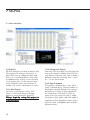
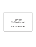
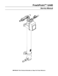
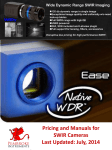
User Manual
Sartorius PMD500
SX-Plus V1.4.0
Software Program
98646-003-07
Contents
3
3
3
4
4
1 Revision history
1.1 V1.4.0
1.2 V1.3.9
1.3 V1.3.8
1.4 V1.3.7
5
2 Introduction
5
3 NIR
6
6
6
6
6
6
6
6
6
6
6
6
7
4 Terms & Abbreviations
4.1 Chemometrics
4.2 Regression
4.3 Regression methods
4.3.1 MLR
4.3.2 PCR
4.3.3 PLS
4.3.4 Other methods
4.3.5 Standard -deviation, -errors
4.3.6 Colinearity
4.3.7 Interference
4.3.8 Pre-treatment
4.3.9 Report abrevations
8
8
8
5 Questions & Answers
5.1 How accurate can I measure?
5.2 How many samples do I need
to make a calibration?
5.3 Transfer a calibration from one
equipment to another
5.4 What to do when it doesn’t
work?
8
8
9
9
9
2
6 Collecting data
6.1 Collecting data using a
separate ID-List
6.2 Collecting data using SXCenter Journal
10
10
10
10
10
10
11
11
11
11
11
12
12
13
13
13
13
13
13
14
14
14
14
14
14
7 SX-Plus
7.1 Users interface
7.2 Projects
7.2.1 New Project
7.2.2 Saving your Project
7.2.3 Project window
7.3 Files
7.3.1 Adding data-files
7.4 Calculation parameters
7.4.1 Sample selector
7.4.2 Selecting and formatting the
target parameter
7.4.3 Standard pre-treatment
7.4.4 Special pre-treatments
7.4.5 Regression methods
7.4.6 Validate
7.4.7 Cross-validation
7.4.8 Auto-Delete
7.4.9 Factors
7.5 Project results
7.5.1 Pre-treat
7.5.2 Modell
7.6 Results
7.7 Graphs
7.8 Export your calibration
7.9 Settings
15
8 Using the calibration
15
9 Calibration maintenance
The following symbols are used in these
instructions:
§ indicates required steps
$ indicates steps required only under certain
conditions
> describes what happens after you have
performed a particular step
– indicates an item in a list
ì indicates hazard
1 Revision history
1.1 V1.4.0
- Valid for software V1.5.0 or later
- Projects must now be named:
*.Parameter.*.prj e.g. Mix.Protein.10-15.prj
a warning will be displayed if name
doesn’t follow this convention
- The project name will automatically
change when you select a parameter and
start the computation
- Clicking a File will automatically add
selectors based on values in field “Recipe”
- Clicking a file will automatically add
existing parameters and their range
- AutoDelete function has been moved into
project and overrides any settings in the
Options. Format is “Calibration
Mahalanobis Validation”
- Calibration of classes using “*” now
automatically creates a usable calibration
file upon export
- You may now denote files as #1, #2, #3
and #4. This will load the exported journal
files from the respective instrument
- Any field named “Recepies” will be
renamed to “Recipes”
- The AutoDelete function did sometimes
not work properly, problem fixed
- License entering dialogue is now visible in
the task-bar.
- A zoomed Wavelength graph now has the
capability to display component
absorbance lines. Components can be
modified in file Bands.txt located in the
install folder
- Upon export and overwriting of a
calibration file only year-month-day is
used; this means that only one calibration
per day is traceable. Traceable file is only
created ones
- In the Mahalanobis / Residium and
Spectral graph the sample reference rather
than ID is used when a item is selected in
the graph
- Removed the need to right click the graph
to get selected objects into the clipboard
1.2 V1.3.9
- Relevant for SX-Plus V1.4.3 or later
- Corrected graph of Residuals
- Cross validation option is now stored in
the project
- A Project using option validation or cross
validation will export without checking
number of factors. Model factors are
defined by minimum validation or cross
validation error
- Cross validation can be maximized for
large data sets resulting in leaving out
more than one sample for each cross
validation. E.g. setting 30 creates 30 subsets for validation; sample ID is persistent
across validation groups
3
- Fixed condition when saving Project to
new location and creating local copy of
data
- Default graph using cross validation is
CVEstimates
- When saveing a project matrix, dialog title
has been changed to “Save Matrix…”
- Project is now blocked for changes when
computing the model
- Incomplete editing of project settings
when starting the calibration process are
automatically completed.
1.3 V1.3.8
- Relevant for SX-Plus V1.4.0 or later
- Corrected import of ISI exported data
- Chapter 7.4.2 Note on range limit
- Note to check Bias removed
1.4 V1.3.7
- Relevant for SX-Plus V1.3.124 or later
- Correction of table of content
- 7.4.2 Corrected missing semicolons
- 7.4.4 Added OSC,EMSC,X2/X0.5
- 7.4.6 Added option 9:-3
4
2 Introduction
3 NIR
Prior to using NIR it is necessary to create
a calibration; this calibration re-computes
the measured spectrum into a desired
property. The creation of a calibration
model is not equal to the adjustment of
intercept and slope, though this i soften
referred to as „calibrating the unit”
Applying NIR spectroscopy is based upon
physical fact that causes energy of certain
wavelength to interact with atom to atom
bonds. These bonds are brought into
vibration causing selective absorption
along the wavelength axis. The amount of
energy converted is proportional to the
concentration of this molecule bond.
Thereby a measurement of the chemical
composition is possible.
NIR is a secondary method, thus it in
almost all cases require prior knowledge
of the composition of the samples
measured in the calibration development
phase.
To create a calibration model the samples
are anlaysed using the NIR spectrometer
as well as applicable primariy methods.
In most cases a calibration is used to
determine a concentration property e.g
%Moisture or %Protein. In some cases the
sample is classified as Type, Good or Bad.
To develop a calibration the samples need
to cover all future expected variations –
not only in the target properties but also
other such as sample temperature or
particle-size.
Since a molecule is build of a plurality of
bonds it is necessary to measure more
than one wavelength to analyse the
sample. These molecules are also subject
to measurable changes due to e.g.
temperature. Measurement in different
wavelength regions causes different pros
and cons. Measurement above 2.5um
causes the bands to be well separated and
a relatively small sample set may be used
for calibration; the con is that the
penetration depth of these wavelengths is
low and that the sample needs to be
prepared prior to measurement by
extraction using a solvent or grinding the
sample – this makes long wavelength non
suitable for on-line analysis. The shorter
wavelengths suffer from more
interference requiring a larger sample set
for training; the pro is that the
measurement may be conducted without
sample preparation – suitable for online
analysis.
5
4 Terms & Abbreviations
4.1 Chemometrics
Is an expression often used in
conjunction with NIR. It signifies the
interpretation of spectral data to
determine chemical composition with the
use of mathematical methods.
4.2 Regression
Is a mathematical term for solving an
equation for its un-knowns.
4.3 Regression methods
The mathematical or procedural way by
which the equation is determined.
4.3.1 MLR
Abbreviation for „Multiple Linear Regression“. Is the most common method of
solving equations where you have many
variables that in a linear combination
represent the target. Various methods are
use depending on numerical and stability
properties of your data, SVD (Singualr
value decomposition) or RR (Ridge
Regression).
4.3.2 PCR
Abbreviation for „Principal Component
Regression“ – This method is a
combination of data-reduction and MLR,
where by the data is approximated by a
fewer number of variables that are later
used to solve the equation.
4.3.3 PLS
Abbreviation for „Partial Least Squares“, is
the most common method applied to
calculate calibration models. This method
is similar to PCR though the eigenvectors
are calculated to maximize the covariance
to the target / target residuum.
6
4.3.4 Other methods
There is a long list of other methods used
in special cases where MLR/PCR/PLS fails
to produce a satisfactory result. Examples
ANN (Artificial Neural Networks), LWR
(Locally weighted regression), SIMCA (Soft
independant model of classes –
specialized PCR)
4.3.5 Standard -deviation, -errors
Standard deviations are often used to
determine the quality of a model. Given a
normal distribution the value represents
the spread of 68% of the population
examined.
4.3.6 Colinearity
Colinearity can be viewed as redundancy
in the data where many of the observed
variables are a linear combination of them
selves; this can also be seen as an
ambiguity in solving the equation since
many solutions give approx. the same
result. Extreme colinearity will in many
cases lead to a poor model; in these cases
you will need to select the appropriate
wavelengths by some means.
4.3.7 Interference
Term that a measured signal is disturbed.
4.3.8 Pre-treatment
Pre-treatments are mathematical
roformating functions of the original
measured signal; these are sometimes
need to e.g. cancel particle size effects.
4.3.9 Report abrevations
In the report window SX-Plus lists various
number these are:
7
5 Questions & Answers
Applying NIR and before applying NIR as
a measurement method many questions
are raised prior to use. Some can be
answered directly but a majority need to
be included as a part of the assessment of
the method.
5.1 How accurate can I measure?
This is probably the most frequently
asked question. Unfortunately there is no
exact answer since there are many
parameters that affect the answer. If we
separate the answer two measuring
subtances that are known to absorb in
the measured region, e.g. Protein/
Moisture or Fat. It is often found that the
measurement accuracy is equal to the
reference method error. One should
however always conduct a study and
determine the error for each application
since other effect as impurity; sample
presentation may have significant effect
on the accuracy obtained.
5.2 How many samples do I need to make
a calibration?
A round number is 100, and this i soften
not a bad number of needed samples.
Again the complexity of the sample
composition determines the actual
number of needed samples. An estimate
can be calculated by taking 20 samples
with various concentration covering the
future expected range and adding 3
samples for each expected disturbance
(variation of other parameters that should
not cause change in estimate). To
optimize your model you will need a
further 10 samples plus 3 samples for
each disturber and a further set of at least
20 real samples to validate your model. In
8
total you will calculate the need for about
100 samples.
5.3 Transfer a calibration from one
equipment to another
The accuracy obtained when a calibration
is transferred is one of the most
important properties – this is partly
affected by instrument to instrument
differences as well as the inner properties
of the calibration. In general a calibration
that works good will transfer – a
calibration that works poor (due to inner
properties) will not transfer. It is often a
benefit if the calibration is developed
using data from more than one
instrument; A transferred calibration
often needs a new defined intercept since
this property isn’t a part of the calibration
model.
5.4 What to do when it doesn’t work?
- Reference values: Determine the error of
your reference values by sending same
sample to your laboratory with different
names.
- Sampling: Validate that your sample
corresponds too your spectra; are the
sample uniquely identified?
6 Collecting data
Measurements made using SX-Center can
directly be exported and used from
withing SX-Plus. Samples analysed in the
„Today-View“ require a separate ID file
where the target values of the samples are
defined.Using the Journal of SX-Center
enables the user to enter the reference
values directly and export a table of data
contining all necessary data for
calculation.
6.1 Collecting data using a separate IDList
1. Start SX-Server
2. Configure sample recognition
3. Start SX-Center
4. Create a Recipe
5. Measure the samples and enter ID’s
6. Export the data
7. Create a Tab separated file using excel
with reference values
6.2 Collecting data using SX-Center
Journal
1. Start SX-Center
2. Select Journal
3. Enter target values
4. Select entry for begin of export
5. Export the data
9
7 SX-Plus
7.1 Users interface
7.2 Projects
SX-Plus maintains all data in project files.
The project file contains references to
other files for e.g. calibration data and
ID-List. It is recommended to store data
in subdirectories relative to the location
of the project file; in this way you may
easily copy data from one location to
another e.g. create a backup on a server.
7.2.1 New Project
To create a new project select „File“;
„New“; in the main menu. A Empty
project is created named „Project1“.
Allways begin by saving this project to
a desired name.
10
7.2.2 Saving your Project
You may save the project by selecting any
item in the project window and click the
save button. You may also save it under a
different name by selecting „File“; „Save
As…“ in the main menu.
7.2.3 Project window
The project is displayed as a tree. Each
entry is defined by its location and/or its
description showed behind each entry in
parentheses. A entry is only regarded if
the check-box is checked. To edit an
entry select the entry text with a single
left mouse-click; pause and click again; a
entry box will be displayed. Some entry’s
will also show a dropdown box with predefined entries.
7.3 Files
7.3.1 Adding data-files
Files a new entry
By double-clicking
is created. By double clicking an entry
you may select a file to use. By singleclick on an entry the file will be displayed
in the Table window.
7.4 Calculation parameters
There are a number of settings that
control the way your date is computed.
The following are the minimum used:
1. (Query) Defines the mask used to
query the data in your data-tables.
2. (Y) Defines the target parameter
3. (Pretreat1) Basic pretreatment1
4. (Pretreat#) Optional further
pretreatments
5. (Type) Regression method
6. (Validate) Samples used to validate
your model
7.4.1 Sample selector
The selection of samples is defined by a
query. A field in each Table is compared
to a mask. The following examples apply:
- Recipe = Salt selects all samples that have
been measured with the Recipe „Salt“.
- Recipe = * selects all spectra’s
- Recipe = *[anr]* selects all spectra’s
measured with Recipes containing an a, n
or r.
7.4.2 Selecting and formatting the
target parameter
The target parameter can be defined and
formatted in the following way:
- ID Protein 0 100 0.0% Target values are
read by comparing the data-tables ID field
with your ID-List, values in the field
„Protein“of your ID-list defines the target.
Output is formatted with one decimal digit
followed by a percent sign.
- Moisture 10 20 0.00% Targets are
selected from your data-table in the range
of 10 to 20. Output is formatted using 2
decimal digits followed by a percent sign.
- Ash 0.3 0.5 0.5 0.9 0.000% Target is
defined by the field „Ash“ in your datatable. The calibration defines two zero
levels; one for samples between 0.3 and
0.5 and one for samples between 0.5 and
0.9. Output is formatted with 3 decimal
digits.
- Class 0 4 ?;Flour;Wheat;Durum;? The
field „Class“ in your data table is used to
define targets – Flour will be represented
by a numerical one, Wheat by 2 and
Durum by 3.
- Class 0 4 ?;Flour;Wheat/Durum;? The
field „Class“ in your data table is used to
define targets – Flour will be represented
by a numerical one, Wheat and Durum by
2.
Note.
Range limits must be formatted using a
decimal „.“ not comma, independent of
regional settings!
11
7.4.3 Standard pre-treatment
The elements of a diode array are
statically aligned along the wavelengthrange of the spectrometer. Therefore it is
required to recompute the absorbencies
determined by measurement to a fixed
scheme and allow combination of data
from several units and transfer of a model
from one equipment to another. This pretreatment is mandatory.
- SNVT Subtracts the average and divides by
the standard-deviation of the vector.
Example:
Spline2 #1 #2 #3 1050 1750 10
Recalculates the measured spectrum to a
vector representing the absorbencies from
1050 to 1750nm with a spacing of 10
nanometres.
- OSC Computes a model of the data that is
perpendicular to the modelling target and
subtracts it from the observations
7.4.4 Special pre-treatments
Mathematical pre-treatments are used to
reformat / reshape the data. These can
effectively be used to cancel out
unwanted effects such as physical
properties (e.g. particle-size) and to
linear-rise the response. Correctly applied
pre-treatment often yield a more precise
and robust model.
- EMSC 2 Computes a second order fit of
the means spectrum to the spectra and
remove it from the data
- NOIMAGE Removes image data from the
observations if present
- MEAN Subtracts the mean of your vector
- SMOOTH 2 Smoothing over 5 data-points
along each vector
- DG 1 5 3 Computes first derivative using
5 data-points and a smoothing window of
three data points
- DG 2 3 5 Compotes second derivative
using 3 data-points and a smoothing
window of five data-points
12
- AVG Calculated the average of repeated
measurements. Repeated measurements
hold same sample ID
- AVG 2 Calculated the average of two
consecutive x and y values irrespective of
sample ID
- EMSC 1 Computes a second order fit of to
the spectra and remove it from the data
- X2 X0.5 Power transformation
7.4.5 Regression methods
Determine the regression method.
Examples:
PCR - Standard PCR-Method
7.4.7 Cross-validation
Determine the number of sections to
divide the calibration set into where each
section is left out once in order to
determine statistics for these left out
samples during regression.
PLS - Standard PLS-Method
PLS2 - Standard PLS2-Method
7.4.8 Auto-Delete
Determine what samples to remove from
the calibration and validation data.
XLS - PLS with second derivative
RR - Ridge Regression (MLR)
If a plus sign is added to the method the
software will automatically select
significant wavelengths (68%
Relevance) for each factor. E.g. PLS+
or RR+ , a double plus E.g PLS++ will
select 95% relevance, a tripple plus is
not supported.
7.4.6 Validate
With this setting you determine the
samples used to optimize / validate the
calculation during model development:
2 - Selects every second spectra for
validation
4:2 - Selects 2 samples in each group of
four samples for validation
9:-3 - Selects the last 3 samples in a
group of nine for validation
3 25 4 – Removes any samples from the
calibration data with a standardized
residual larger than 3, removes any sample
from the calibration or validation data
with a Mahalanobis distance larger than
25 and any samples in the validation data
with a standardized residual larger than 4
Note:
When using Automatic recalibration these
deletes are non persistent; thus reevaluation will occur upon each recalibration
7.4.9 Factors
Determine the number of factors for your
model. Leaving this option „unchecked“
during calculation will lead the software
to optimize the number of factors to use.
7.5 Project results
Results of the computations can be
viewed as a numerical table or graphically
by selecting one of the bold entries in the
project.
-10 - Selects the last 10 spectra for
validation.
13
7.5.1 Pre-treat
Pretreat
Wavelengths Vector of used
wavelengths
SNRs
Vector of instrument
serial-numbers
WLCs
Vector of instrument
wavelength calibrations
Means
Matrix of spectral means
for each data-set
Variations
Matrix of variance for
each data-set
7.5.2 Modell
Wavelengths Vector of used
wavelengths
Indexes
Vector of references
to used samples
IDs
Vector of sample
ID’s
Center
Average Target
Target
Vector of Target
Zero
Vector of mean spectra
Observations Matrix of spectras
Weights
Matrix of projected
X-values
Loads
Matrix of projected
Y-values
Regressions
Matrix of regression
vectors
Press
2 Vectors representing
residuum for
calibration and
validation
Scores
Estimated Y - values
Bias
Zero levels.
Estimates
Estimated Target values
Residuals
Residuals of estimates
IDResiduals
TEstimates
Estimates over time
TResiduals
Residuals over time
Validation
In this group you find
above entries for your
validation data
14
7.6 Results
By selecting „Compute“ from the main
menu the results of the computation is
shown in the report window. This report
discloses information about used data,
statistics and possible abnormalities.
7.7 Graphs
By selecting various matrices/vectors in
the project the data is graphically
displayed.
3D graphs may be rotated by holding
down the left mouse button and moving
the mouse.
By holding the „Ctrl“ down and clicking
with the left mouse button references can
be selected. By clicking the right mouse
button still holding the „Ctrl“-key down
copies these references to the clipboard.
To e.g. delete the marked sample – enter
the delete leaf of the project and paste
the sample references.
If not samples have been selected –
clicking the right mouse button will copy
a „white“ background graph into the
clipboard. This may be pasted into Word
or Excel.
7.8 Export your calibration
From the menu select „Project“ / „Export…“ Select a location and enter the
name of your calibration. It is common
practice to keep a version number,
parameter name and range.
7.9 Settings
Further settings can be modified selecting
„View“ / „Options“ from the main menu
8 Using the calibration
9 Calibration
maintenance
To use the calibration, place them in the
„Calibrations“ folder of your SX-Suite
installation. It will automatically appear in
the list of available calibrations when you
edit a Recipe.
It is in the beginning often necessary to
add data to an earlier project. Open the
project, select the data table. From the
menu select „File“ „Merge…“ and select
the file containing the new data. The new
data will be added to the end of the
table. Re-compute and export the model.
15
Sartorius AG
Weender Landstrasse 94-108
37075 Goettingen, Germany
Phone +49.551.308.0
Fax
+49.551.308.3289
www.sartorius.com
Copyright by Sartorius AG,
Goettingen, Germany.
All rights reserved. No part
of this publication may
be reprinted or translated in
any form or by any means
without the prior written
permission of Sartorius AG.
The status of the information,
specifications and illustrations
in this manual is indicated
by the date given below.
Sartorius AG reserves the
right to make changes to
the technology, features,
specifications and design
of the equipment without notice.
Status:
August 2009, Sartorius AG,
Goettingen, Germany
Printed in Germany on paper
that has been bleached without any use
of chlorine. W1A0OO - KT
Publication No.: WPM6071-e09082