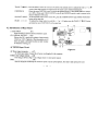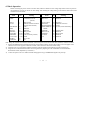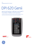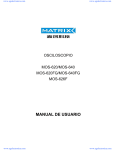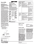
1
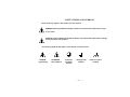
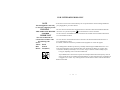
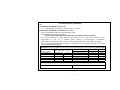
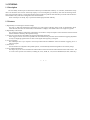
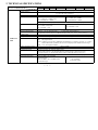
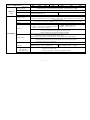
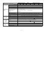
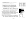
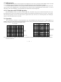
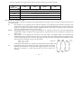
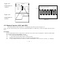
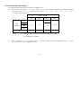
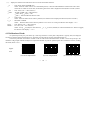
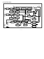
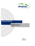
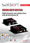
GOS-6xxG Family
Dual Trace Oscilloscope
Members Of The Family
50MHz
20MHz
20MHz
50MHz
50MHz
35MHz
20MHz
Cursor Readout With Delayed Sweep ………
Cursor Readout ……….……….……….……
Basic with Delayed Sweep
Basic With Delayed Sweep ……….…………
Basic ……….……….……….……….………
Basic ……….……….……….……….………
Basic ……….……….……….……….………
GOS-658G
GOS-626G
GOS-623G
GOS-653G
GOS-652G
GOS-635G
GOS-622G
82OS-658G0MG
⎯
i
⎯
⎯
ii
⎯
SAFETY TERMS AND SYMBOLS
These terms may appear in this manual or on the product:
WARNING. Warning statements identify condition or practices that could result in injury
or loss of life.
CAUTION. Caution statements identify conditions or practices that could result in damage
to this product or other property.
The following symbols may appear in this manual or on the product:
DANGER
High Voltage
ATTENTION
refer to Manual
Protective
Conductor
Terminal
Earth(ground)
Terminal
⎯
iii
⎯
Frame or chassis
Terminal
FOR UNITED KINGDOM ONLY
NOTE
As the colours of the wires in main leads may not correspond with the colours marking identified in
This lead/appliance must only your plug/appliance, proceed as follows:
be wired by competent persons
WARNING
The wire which is coloured Green & Yellow must be connected to the Earth terminal marked with
THIS APPLIANCE MUST BE the letter E or by the earth symbol
or coloured Green or Green & Yellow.
EARTHED
The wire which is coloured Blue must be connected to the terminal which is marked with the letter
IMPORTANT
N or coloured Blue or Black.
The wires in this lead are
coloured in accordance with
the following code:
Green/
Yellow: Earth
Blue:
Neutral
Brown: Live(Phase)
The wire which is coloured Brown must be connected to the terminal marked with the letter L or
P or coloured Brown or Red.
If in doubt, consult the instructions provided with the equipment or contact the supplier.
This cable/appliance should be protected by a suitably rated and approved HBC mains fuse : refer
to the rating information on the equipment and/or user instructions for details. As a guide, cable
of 0.75mm² should be protected by a 3A or 5A fuse. Larger conductors would normally require
13A types, depending on the connection method used.
.
Any moulded mains connector that requires removal/replacement must be destroyed by removal
of any fuse & fuse carrier and disposed of immediately, as a plug with bared wires is hazardous if
a engaged in live socket. Any re-wiring must be carried out in accordance with the information
detailed on this label.
⎯
iv
⎯
EC Declaration of Conformity
We
GOOD WILL INSTRUMENT CO.,LTD.
No. 7-1, Jhongsing Rd, Tucheng City, Taipei County 236. Taiwan.
GOOD WILL INSTRUMENT (SUZHOU) CO., LTD.
No.69 Lushan Road, Suzhou New District Jiangsu, China.
declare that the below mentioned products
GOS-622G,GOS-626G,GOS-623G,GOS-635G,GOS-652G,GOS-653G,GOS-658G
are herewith confirmed to comply with the requirements set out in the Council Directive on the
approximation of the Law of Member States relating to Electromagnetic Compatibility
(89/336/EEC,92/31/EEC,93/68/EEC) and Low Voltage Equipment Directive (73/23/EEC, 93/68/EEC).
For the evaluation regarding the Electromagnetic Compatibility and Low Voltage Equipment Directive, the
following standards were applied:
EN 61326-1:Electrical equipment for measurement, control and laboratory use––EMC requirements (1997+A1:1998)
Conducted Emission
Radiated Emission
Current Harmonics
Voltage Fluctuations
----------------------------------------------------
EN 55022 class B
(1994)
EN 61000-3-2
EN 61000-3-3
----------------------------
(1995)
(1995)
----------------------------
Electrostatic Discharge
Radiated Immunity
Electrical Fast Transients
Surge Immunity
Conducted Susceptibility
IEC 1000-4-2
IEC 1000-4-3
IEC 1000-4-4
IEC 1000-4-5
EN 61000-4-6
Power Frequency Magnetic field EN 61000-4-8
Voltage Dip/Interruption
IEC 1000-4-11
Low Voltage Equipment Directive 73/23/EEC
Low Voltage Directive
IEC/EN61010: 2001
⎯
v
⎯
(1995)
(1995)
(1995)
(1995)
(1996)
(1993)
(1994)
1. GENERAL
1.1 Description
The 6xxG family oscilloscopes are dual-channel oscilloscopes with maximum sensitivity of 1 mV/DIV, and maximum sweep
time of 10 nSec/DIV. Each of these oscilloscopes employs a 6-inch rectangular type cathode-ray tube with red internal graticule.
623G, 653G and 658G each has a sweep magnification feature with B sweep whereas 626G and 658G provide the read-out function
which enables an easy read out for settings and cursor measured values.
These oscilloscopes are sturdy, easy to operate and exhibit high operational reliability.
1.2 Features
1) High intensity CRT with high acceleration voltage:
The CRT is a high beam transmission, high intensity type with a high acceleration voltage of 2kV for models 622G, 623G,
635G and 626G, and 12kV for models 652G, 653G and 658G. It displays clear readable traces even at high sweep speeds.
2) High stability with less drift:
The oscilloscope employs a temperature compensation circuit which is newly developed to reduce the drift of base lines and DC
balance disturbance caused by the temperature change.
3) A trigger level lock function which makes the triggering adjustment unnecessary:
A new trigger level lock circuit is incorporated. This circuit eliminates the procedures of the troublesome triggering adjustment
not only for displaying signals but also for that of video signals and large duty-cycle signals.
4) TV sync triggering:
The oscilloscopes have a sync separator circuit incorporated within the TIME/DIV switch for automatic triggering of TV-V
and TV-H signals.
5) Linear focus:
Once the beam focus is adjusted to the optimum position, it is automatically maintained regardless to the intensity change.
6) Cursor readout measurement:
The unique easy-to-use cursor and numerical readouts make waveform observations and measurement faster and accurate. The
on- screen cursors provide seven functions, including ∆V, ∆V%, ∆VdB, ∆T, 1/∆T, DUTY and PHASE (for 626G, 658G only).
⎯
1
⎯
2. TECHNICAL SPECIFICATIONS
MODEL
SPECIFICATIONS
Sensitivity
Sensitivity accuracy
Vernier vertical sensitivity
Frequency bandwidth (-3dB)
Rise time
Input impedance
Square wave characteristics
VERTICAL
AXIS
DC balance shift
Linearity
Vertical modes
Chopping repetition frequency
Input coupling
Maximum input voltage
Common mode rejection ratio
Isolation between channels
20MHz OSCILLOSCOPE
35MHz
50MHz OSCILLOSCOPE
622G
626G
623G
635G
652G
653G
658G
1mV ~ 5V/DIV, 12 steps in 1-2-5 sequence
5mV ~ 5V/DIV: ≤3%, 1mV ~ 2mV/DIV: ≤5%
( 10℃ to 35℃(50℉ to 95℉) )
<< 5 DIV at the center of display>>
To 1/2.5 or less of panel-indicated value.
5mV~5V/DIV:DC~20MHz (622G,623G,626G)
5mV~5V/DIV : DC~50MHz,
5mV~5V/DIV:DC~35MHz (635G)
1mV~2mV/DIV:DC~15MHz
1mV~2mV/DIV:DC~10MHz
AC coupling: Low limit frequency 10Hz (With reference to 100kHz, 8DIV. Frequency response with -3dB.)
5mV~5V/DIV:≈ 17.5ns(622G,623G,626G)
5mV~5V/DIV:≈ 7ns,
5mV~5V/DIV:≈ 10ns(635G)
1mV~2mV/DIV: ≈ 23ns
1mV~2mV/DIV: ≈ 35ns
1M ohm ±2% // Approx. 25pF
Overshoot : ≤ 5% (At 10mV/DIV range )
<< 5 DIV at the center of display>>
Other distortions and other ranges: 5% added to the above value ( 10℃ to 35℃ (50℉ to 95℉) ).
5mV ~5V/DIV: ±0.5DIV, 1mV ~ 2mV/DIV: ±2.0DIV
< ±0.1 DIV of amplitude change when waveform of 2 DIV at graticule center is moved vertically.
CH1 : CH1 single channel.
CH2 : CH2 single channel.
DUAL : CHOP/ALT are auto-set by TIME/DIV switch(CHOP:0.5s~5ms/DIV, ALT:2ms~0.1μs/DIV).
When CHOP switch is pushed in, the two traces are displayed in the CHOP mode at all range.
ADD : CH1 + CH2 algebraic addition.
Approx. 250kHz
AC, DC, GND
400V (DC+AC peak), AC: frequency 1kHz or lower.
When set probe switch at 1:1, the maximum effective readout is 40Vpp (14Vrms at sine wave),
or set probe switch at 1:10, the maximum effective readout is 400Vpp(140Vrms at sine wave).
50:1 or better at 50kHz sinusoidal wave. (When sensitivities of CH1 and CH2 are set equally)
>1000:1 at 50kHz, >30:1 at 20MHz
> 1000:1 at 50kHz
(622G,623G,626G)
> 30:1 at 50MHz
>1000:1 at 50kHz , >30:1 at 35MHz (635G)
(At 5mV/DIV range)
(At 5mV/DIV range)
⎯
2
⎯
MODEL
20MHz OSCILLOSCOPE
35MMz
50MHz OSCILLOSCOPE
622G
626G
623G
635G
652G
653G
658G
Approx. 100mV/DIV without termination, 50mV/DIV with 50 ohm termination.
CH1 signal output
Bandwidth (-3dB) : 622G/623G/626G/635G : 20MHz, 652G/653G/658G : 40MHz
CH2 INV BAL.
Balanced point variation: ≤ 1 DIV ( Reference at center graticule.)
VERTICAL
>8DIV at 20MHz
Dynamic range
>8DIV at 50MHz
AXIS
>5DIV at 35MHz (635G only)
Leading edge can be monitored.
─
─
─
─
Signal delay
CH1, CH2, LINE, EXT ( CH1 and CH2 can be selected only when the vertical mode is DUAL or ADD.
Triggering source
In ALT mode, if the TRIG. ALT switch is pushed in, it can be use for alternate triggering of two different source. )
AC, HF-REJ, TV, DC
Coupling
( TV-V/TV-H can be auto-set by TIME/DIV range. TV-V: 0.5s-0.1ms/DIV; TV-H: 50μs-0.1μs/DIV)
Polarity
+/−
DC~5MHz: 0.5 DIV ( EXT: 0.1V )
DC~10MHz : 0.5 DIV ( EXT: 0.1V )
5~20MHz : 1.5 DIV ( EXT: 0.2V )(622G,623G,626G)
10~50MHz : 1.5 DIV ( EXT: 0.2V )
5~35MHz : 1.5 DIV ( EXT: 0.2V)(635G)
Sensitivity
TV (video signal): 2.0 DIV ( EXT: 0.2V )
AC coupling: Attenuate signal components of lower than 10Hz.
HF-REJ: Attenuate signal components of higher than 50kHz.
AUTO : Sweeps run in the free mode when no triggering input signal is applied.
TRIGGERING
(Applicable for repetitive signals of frequency 50Hz or over.)
NORM : When no triggering signal is applied, the trace is in the READY state and not displayed.
Triggering modes
SINGLE : One-shot sweep with triggering signal. Can be reset to the READY state by means of the RESET switch.
The READY lamp (LED) turns on when in the READY state or in the sweep operation
(623G, 626G , 652G , 653G and 658G only)
LEVEL LOCK and ALT
Satisfies the value of the above trigger sensitivity plus 0.5 DIV (EXT: 0.05V) for signal of duty cycle 20:80.
Repetition frequency:50Hz~20MHz(622G,623G,626G)
Repetition frequency : 50Hz ~ 40MHz
triggering
Repetition frequency : 50Hz ~35MHz (635G)
EXT HOR input terminal is used in common.
EXT triggering signal input
1M ohm ±2% // approx. 35pF
Input impedance
Max. input voltage
100V (DC+AC peak), AC: Frequency not higher than 1kHz
The A triggering signal of main sweep is used as the B triggering signal (623G,653G &658G).
B triggering signal.
SPECIFICATIONS
⎯
3
⎯
MODEL
SPECIFICATIONS
Horizontal axis display
A sweep(main sweep ) time
Sweep time accuracy
Vernier sweep time control
Hold off time
B sweep delay system
HORIZONTAL B sweep(delay sweep) time
Sweep time accuracy
AXIS
Delay time
Delay jitter
Sweep magnification
×10MAG sweep time accuracy
Linearity
Position shift caused by x10MAG
Sensitivity
Sensitivity accuracy
X-Y MODE
Frequency bandwidth
X-Y phase difference
Sensitivity
EXT HOR
MODE
Z AXIS
Frequency bandwidth
Phase difference between vertical
axis
Sensitivity
Frequency bandwidth
Input resistance
Maximum input voltage
20MHz OSCILLOSCOPE
35MHz
50MHz OSCILLOSCOPE
622G
626G
623G
635G
652G
653G
658G
A, A INT, B, B TRIG’D (623G, 653G&658G)
0.1μs ~ 0.5s/DIV, 21 steps in 1-2-5 sequence
±3%, (10℃ to 35℃ ( 50℉ to 95°F ) )
≤ 1/2.5 of panel-indicated value
Continuous variable ≧ twice sweep length (time) at 0.1µSec~1mSec/DIV ranges.
Continuous delay and triggered delay
0.1μs~0.5ms/DIV, 12 steps
(623G, 653G&658G)
±3%, (10℃ to 35℃( 50℉ to 95℉ ) )
1μs ~ 5ms
≤ 1/10000
10 times ( maximum sweep time 10ns/DIV )
0.1μs~50ms/DIV ±5%, 10ns~50ns/DIV ±8% (10℃ to 35℃(50℉ to 95℉))
NORM:±3%, ×10MAG:±5% (±8% for 10ns~50ns/DIV)
Within 2 div. at CRT screen center
Same as vertical axis.(X-axis:CH1 input signal; Y-axis:CH2 input signal.)
NORM:±4%, ×10MAG: ±6% (10℃ to 35℃(50℉ to 95℉))
DC ~ 1MHz (-3dB)
DC ~ 2MHz (-3dB)
≤3º at DC ~50kHz
≤3º at DC ~100kHz
Approx. 0.1V/DIV (Trace swept by an external horizontal signal applied to the EXT TRIG IN terminal.
Vertical axis modes are CH1,CH2,DUAL and ADD modes in the CHOP mode.)
DC ~ 1MHz (-3dB)
DC ~ 2MHz (-3dB)
≤ 3º at DC ~50kHz
≤ 3º at DC ~100kHz
3 Vp-p ( Trace becomes brighter with negative input.)
DC ~5MHz
Approx. 5k ohm
50 V ( DC+AC peak, AC frequency≤ 1kHz )
⎯
4
⎯
SPECIFICATIONS
MODEL 20MHz OSCILLOSCOPE 35MHz
622G
626G
623G
635G
Waveform
Frequency
CALIBRATION Duty ratio
Output voltage
VOLTAGE
Output impedance
Type
Phosphor
Acceleration voltage
CRT
CURSOR
READOUT
(626G,658G)
Effective screen size
Graticule
Cursor measurement functions
Cursor display format
Cursor resolution
Effective cursor range from center
graticule
Panel setting display
Approx. 2 kV
652G
50MHz OSCILLOSCOPE
653G
658G
Positive-going square wave
1 kHz ±5%
Within 48:52
2 Vp-p ±2%
Approx. 2 k ohm.
6-inch rectangular type, internal graticule.
P 31
Approx. 12 kV
8 × 10 DIV ( 1 DIV = 10mm(0.39in))
Internal;
continuous adjustable illumination (623G,626G,652G,653G,658G only)
△V ,△V% ,△VdB, △T ,1/△T ,DUTY ,PHASE
▽(DELTA), ▼(REF)
1/25 DIV
Vertical:
±3 DIV
Horizontal: ±4 DIV
V/DIV,V-MODE, INV, ALT/CHOP, UNCAL, ADD(SUB), ×10MAG,
PROBE(×1/×10), X-Y, A T/D, TV-V/H,
B T/D(for 658G only)
Measurement category I is for measurements performed on circuits not directly connected to MAINS.
Measurement category II is for measurements performed on circuits directly connected to the low voltage installation.
Measurement category III is for measurements performed in the building installation.
Measurement category IV is for measurements performed at the source of the low-voltage installation.
⎯
5
⎯
Line Power Requirements
Voltage
Frequency
Power consumption
: AC 100V, 120V, 220V, 230V
±10% selectable
: 50Hz or 60Hz
: Approx. 70VA, 60W(max.)
Operating Environment
Indoor use
Altitude up to 2000 m
Ambient temperature :
To satisfy specifications : 5° to 35℃ ( 41° to 95° F )
Maximum operating ranges: 0° to 40℃( 32 °to 104° F )
Relative humidity:85% RH(max.) non condensing
Installation Category
Accessories
Power cord…...............1
Instruction manual.…..1
Probes......................... 2
II
Pollution degree 2
Mechanical Specifications
Dimensions
: 310 W x 150 H x 455 D (mm)
Weight
: Approx.8.2Kg (18 lbs)
Storage Temperature & Humidity
-10° to 70℃,70%RH (maximum)
3. PRECAUTIONS BEFORE OPERATING THE OSCILLOSCOPE
3.1 Unpacking the Oscilloscope
The oscilloscope is shipped from the factory after being fully inspected and tested. Upon receiving the instrument, immediately unpack
and inspect it for any damages that might have been sustained during transportation. If any sign of damage is found, immediately notify the
bearer and/or the dealer.
3.2 Checking the Line Voltage
These oscilloscopes will operate on any one of the line voltage shown in the table below, by inserting the line voltage selector plug in the
corresponding position on the rear panel. Before connecting the power plug to an AC line outlet, make sure the voltage selector is set to the
correct position corresponding to the line voltage. Note the oscilloscope may be damaged if it is connected to the wrong AC line voltage.
WARNING. To avoid electrical shock the power cord protective grounding
conductor must be connected to ground.
⎯
6
⎯
When line voltages are changed, replace the required fuses shown below.
Line voltage
100V
120V
Range
90-110V
108-132V
Fuse
Line voltage
220V
230V
T 0.63A
250V
Range
198-242V
207-250V
Fuse
T 0.315A
250V
WARNING. To avoid personal injury, disconnect the power cord
before removing the fuse holder.
3.3 Environment
The normal ambient temperature range of this instrument is 0° to 40°C (32° to 104°F). Operation of the instrument above this
temperature range may cause damage to the circuits.
Do not use the instrument in a place where strong magnetic or electric field exists. Such fields may disturb the measurement.
3.4 Equipment Installation, and Operation
Ensure there is proper ventilation for the vents in the oscilloscope case.
If this equipment is used in a manner not specified by the manufacturer, the protection provided by the equipment may be impaired.
3.5 CRT Intensity
To prevent permanent damage to the CRT phosphor, do not make the CRT trace excessively bright or leave the spot stationary for an
unreasonably long time.
3.6 Withstanding Voltages of Input Terminals
The withstanding voltages of the instrument input terminals and probe Input terminals are as shown in the following table. Do not apply
voltages higher than these limits.
⎯
7
⎯
⎯
8
⎯
⎯
9
⎯
⎯
10
⎯
4. OPERATION METHOD
4.1 Introduction of Front Panel
CRT :
POWER.......................(9)
Main power switch of the instrument.
When this switch is turned on, the LED (8) is also turned on.
INTEN.........................(2)
Controls the brightness of the spot or trace.
B INTEN......................(3)(623G,653G & 658G only)
Semi-fixed potentiometer for adjusting trace intensity when in B sweep mode.
READOUT INTEN......(7)(626G & 658G only)
Semi-fixed potentiometer for adjusting intensity of the readout and cursors.
FOCUS........................(4)
For focusing the trace to the sharpest image.
ILLUM........................(6)(Except 622G & 635G)
Graticule illumination adjustment.
TRACE ROTATION....(5)
Semi-fixed potentiometer for aligning the horizontal trace in parallel with graticule lines.
FILTER........................(42)
Filter for ease of waveform viewing.
Vertical Axis:
CH 1 (X) input.............(12)
Vertical input terminal of CH 1.
When in X-Y operation, X-axis input terminal.
CH 2 (Y) input.............(16)
Vertical input terminal of CH 2.
When in X-Y operation, Y-axis input terminal.
AC-DC-GND...............(11)(15)
Switch for selecting connection mode between input signal and vertical amplifier.
AC : AC coupling
DC : DC coupling
⎯
11
⎯
GND : Vertical amplifier input is grounded and input terminals are disconnected.
VOLTS/DIV...............(10)(14)
Select the vertical axis sensitivity, from 1mV/DIV to 5V/DIV in 12 ranges.
VARIABLE................(13)(17)
Fine adjustment of sensitivity, with a factor of ≥1/2.5 of the indicated value. When in the CAL position, sensitivity is
calibrated to indicated value.
POSITION..................(40)(37)
Vertical positioning control of trace or spot.
VERT MODE.............(39)
Select operation modes of CH 1 and CH 2 amplifiers.
CH 1 : The oscilloscope operates as a single-channel instrument with CH 1 alone.
CH 2 : The oscilloscope operates as a single-channel instruments with CH 2 alone.
DUAL : The oscilloscope operates as a dual-channel instrument both CH 1 and CH 2. CHOP/ALT are automatic
changed by TIME/DIV switch (18). When CHOP (41) button is pushed in, the two traces are displayed in
the CHOP mode at all ranges.
ADD : The oscilloscope displays the algebraic sum (CH 1 + CH 2) or difference (CH 1 - CH 2) of the two signals.
The pushed in state of CH 2 INV(36) button is for the difference (CH 1 - CH 2).
Triggering:
EXT TRIG(EXT HOR) input terminal........(23)
Input terminal is used in common for external triggering signal and external horizontal signal. To use this terminal, set
SOURCE switch (26) to the EXT position.
SOURCE....................................................(26)
Select the internal triggering source signal, and the EXT HOR input signal.
CH 1 (X-Y)
: When the VERT MODE switch(39) is set in the DUAL or ADD state, select CH 1 for the internal
triggering source signal. When in the X-Y mode, select CH 1 for the X-axis signal.
CH 2
: When the VERT MODE switch(39) is set in the DUAL or ADD state, select CH 2 for the internal
triggering source signal.
TRIG.ALT(24) :When the VERT MODE switch(39) is set in the DUAL or ADD state, and the SOURCE
switch(26) is selected at CH 1 or CH 2, with the engagement of the TRIG.ALT switch(24), it will
alternately select CH 1 & CH 2 for the internal triggering source signal.
⎯
12
⎯
LINE
EXT
: To select the AC power line frequency signal as the triggering signal.
: The external signal applied through EXT TRIG(EXT HOR) input terminal(23) is used for
the external triggering source signal. When in the X-Y, EXT HOR mode, the X-axis operates with
the external sweep signal
COUPLING.............(25)
Select COUPLING mode(25) between triggering source signal and trigger circuit; select connection of TV sync trigger circuit.
AC
: AC coupling
DC
: DC coupling
HF REJ : Removes signal components above 50kHz(-3dB).
TV
: The trigger circuit is connected to the TV sync separator circuit and the triggered sweeps synchronize with
TV-V or TV-H signal at a rate selected by the TIME/DIV switch(18)
TV-V: 0.5 s/DIV - 0.1ms/DIV
TV-H: 50µs/DIV - 0.1µs/DIV
SLOPE.....................(22)
Select the triggering slope.
“+” : Triggering occurs when the triggering signal crosses the triggering level in positive-going direction.
“−” : Triggering occurs when the triggering signal crosses the triggering level in negative-going direction.
LEVEL.....................(30)
To display a synchronized stationary waveform and set a start point for the waveform.
Toward “+” : The triggering level moves upward on the display waveform.
Toward “−” : The triggering level moves downward on the display waveform.
LOCK(29) : Triggering level is automatically maintained at optimum value irrespective of the signal amplitude (from
very small to large amplitudes), requiring no manual adjustment of triggering level.
HOLD OFF........…(31)
Used when the signal waveform is complex and stable triggering cannot be attained with the LEVEL knob alone.
⎯
13
⎯
TRIGGER MODE...…………..(28)
Select the desired trigger mode.
AUTO
: When no triggering signal is applied or when triggering signal frequency is less than 50 Hz, sweep runs
in the free run mode.
NORM : When no triggering signal is applied, sweep is in a ready state and the trace is blanked out. Used primarily
for observation of signal ≤ 50 Hz.
SINGLE : Use for single sweep.(Except 622G & 635G)
Push to RESET: Operation(one-short triggering operation), and in common as the reset switch. When
these three buttons are disengaged, the circuit is in the single trigger mode. The circuits is reset as this button is
pressed. When the circuit is reset, the READY lamp turns on. The lamp goes out when the single sweep
operation is over.
Time Base
(A) TIME/DIV........………......(18)
Select the sweep time of the A sweep. (A and B sweep in common for 658G only, B TIME/DIV < A TIME/DIV)
B
TIME/DIV...........………...(43) (623G&653G only)
Select the sweep time of delayed sweep (B sweep).
SWP.VAR............………….....(21)
Vernier control of sweep time. When SWP.UNCAL(19) button is pushed in, the sweep time can be made slower by a factor ≥2.5
of the indicated value. The indicated values are calibrated when this button is not pushed in.
POSITION..........……………..(34)
Horizontal positioning control of the trace or spot.
×10 MAG............………….(33)
When the button is pushed in, a magnification of 10 occurs.
DELAY TIME...........… ........(44)( 623G&653G only)
Vernier control of the delay time selected by the A TIME/DIV(18) and B TIME/DIV(43) switch to finely select the portion of the
A sweep waveform to be magnified.
HORIZ. DISPLAY MODE.......(38)( 623G, 653G & 658G only)
Select A and B sweep modes as follows:
A
: Main sweep(A sweep) mode for general waveform observation.
A INT : This sweep mode is used when selecting the section to be magnified of A sweep, in preparation for delayed sweep.
The B sweep section(delayed sweep) corresponding to the A sweep is displayed with a high intensity beam.
⎯
14
⎯
B
: Display the delayed sweep(B sweep) alone.
B TRIG‘D : Select between continuous delay and triggered delay.
Disengaged : For continuous delay. The B sweep starts immediately after the sweep delay time set by A
TIME/DIV and B TIME/DIV switch and DELAY .TIME knob has elapsed.
Engaged : For triggered delay. The B sweep starts when the triggering pulse is applied after the sweep delay
time set by A TIME/DIV and B TIME/DIV switch and DELAY TIME knob has elapsed.
(The triggering signal is used in common for both A sweep and B sweep).
X-Y.................……….........(27)
Press the X-Y button to enable X-Y operation.
Others
CAL……….....………..........(1)
This terminal delivers the calibration voltage of 2 Vp-p, 1kHz, positive square wave.
page 5 technical specification for tolerance.
The output resistance is 2k ohm see
GND................………….....(20)
Ground terminal of oscilloscope mainframe.
Readout Function (Only available in 626G & 658G)
CURSOR measurement........(32)
CURSOR ON/OFF
: Press the button to turn on/off the cursor measurement.
CURSOR FUNCTION : Press the button to select the measurement functions.
: Voltage difference measurement.
∆V
: Voltage difference measurement in percentage(5 div =100% ref.)
∆V%
∆VdB : Voltage gain measurement(5 div = 0dB ref. , ∆VdB = 20 log∆div/5div)
: Time difference measurement.
∆T
: Frequency measurement.
1/∆T
DUTY : Duty cycle or time difference percent(∆T%) measurement(5 div =100% ref.)
PHASE : Phase measurement(5 div = 360° ref.)
⎯
15
⎯
⎯
16
⎯
4.3 Basic Operation
Before connecting the power cord to an AC line outlet, make sure that the AC line voltage input switch on the rear panel of
the instrument is correctly set for the AC line voltage. After ensuring the voltage setting, set the switches and controls of the
instrument as shown below:
Item
No
POWER
INTEN
(9)
(2)
FOCUS
ILLUM
(4)
(6)
VERT MODE
CHOP
CH 2 INV
POSITION
VOLTS/DIV
VARIABLE
AC-DC-GND
SOURCE
COUPLING
(39)
(41)
(36)
(40)(37)
(10)(14)
(13)(17)
(11)(15)
(26)
(25)
Setting
Item
Disengage position(OFF)
Clockwise(3-o‘clock
position)
Mid-position
Full anti-clockwise Position
(Except 622G & 635G)
CH 1
Released
Released
Mid-position
0.5V/DIV
CAL(clockwise position)
GND
Set to CH 1
AC
No
Setting
SLOPE
TRIG ALT
(22)
(24)
+
Released
LEVEL LOCK
HOLDOFF
TRIGGER MODE
HORIZ DISPLAY
MODE
TIME/DIV
SWP.UNCAL
POSITION
x10 MAG
X-Y
(29)
(31)
(28)
(38)
Pushed in
MIN(anti-clockwise)
AUTO
A (623G,653G &658Gonly)
(18)
(19)
(34)
(33)
(27)
0.5mSec/DIV
Released
Mid-position
Released
Released
After setting the switches and controls as mentioned, connect the power cord to the AC line outlet, and then, continue as follows:
1) Engage the POWER switch and make sure that the power LED is turned on. In about 20 seconds, a trace will appear on the
CRT screen. If no trace appears in about 60 seconds, counter check the switch and control setting.
2) Adjust the trace to an appropriate brightness and image with the INTEN control and FOCUS control respectively.
3) Align the trace with the horizontal center line of the graticule by adjusting the CH 1 POSITION control and TRACE
ROTATION control (adjustable by screwdriver).
4) Connect the probe to the CH 1 INPUT terminal and apply the 2Vp-p CALIBRATOR signal to the probe tip.
⎯
17
⎯
5)
6)
7)
8)
Set the AC-DC-GND switch to the AC state. A waveform as shown in the figure 4-3
will be displayed on the CRT screen
Adjust the FOCUS control so that the trace image appears sharply.
For signal viewing, set the VOLTS/DIV switch and TIME/DIV switch in appropriate
positions so that signal waveform is displayed clearly.
Adjust the ∆∇ POSITION and < > POSITION controls in appropriate positions so
that the displayed waveform is aligned with the graticule and voltage(Vp-p) and
period(T) can be read conveniently. The above are the basic operating procedures
of the oscilloscope. The above procedures are for single-channel operation with
CH 1. Single-channel operation with CH 2 can also be achieved in a similar manner.
Further operation methods are explained in the subsequent paragraph.
4.4 Dual-channel Operation
Change the VERT MODE switch to the DUAL states so that trace (CH 2) is also
displayed(The explanation in the proceeding section is of CH 1). At this state of procedure, the
CH 1 trace is the square wave of the calibrator signal and the CH 2 trace is a straight line since no
signal is applied to this channel yet.
Now, apply the calibrator signal to the vertical input terminal of CH 2 with the probe
as is the case for CH 1. Set the AC-DC-GND switch to the AC state. Adjust vertical POSITION
knobs(40) and (37) so that both channel signals are displayed as shown in Figure4-4.
When in the dual channel operation (DUAL or ADD mode), the CH 1 or CH 2 signal must
be selected for the triggering source signal by means of the SOURCE switch. If both CH 1 and
CH 2 signals are in a synchronized relationship, both waveforms can be displayed stationary;
if not, only the signal selected by the SOURCE switch can be stationary. If the TRIG.
ALT push switch is engaged, both waveforms can be stationary (Do not use “CHOP”
and “ALT” triggering source switch at the same time).
Selection between CHOP mode and ALT mode are automatically made by the TIME/DIV
switch shown in Figure 4-5. The 5mSec/DIV and lower ranges are used in the CHOP mode and
the 2ms/DIV and higher ranges are used in the ALT mode.
When the CHOP push switch is engaged, the two traces are displayed in the CHOP
operation at all ranges. The CHOP operation has priority over the ALT operation.
Signal of CH1
Signal of CH2
Figure 4-4
Figure 4-5
⎯
18
⎯
4.5 ADD Operation
An algebraic sum of the CH 1 and CH 2 signals can be displayed on the screen by setting the VERT MODE switch to the ADD
state. The displayed signal is the difference between CH 1 and CH 2 signals if the CH 2 INV push switch is engaged.
For accurate addition or subtraction, it is a prerequisite that the sensitivities of the two channels are adjusted accurately at the same
value by means of the VARIABLE knobs. Vertical positioning can be made with the ∆∇ POSITION knob of either channel. In view of
the linearity of the vertical amplifiers, it is most advantage to set both knobs in their mid-positions.
4.6 X-Y Operation and EXT HOR Operation
When the TIME/DIV switch is set in the X-Y/EXT HOR state, the internal sweep circuit is disconnected and the trace in the
horizontal direction is driven by the signal selected by the SOURCE switch. When the SOURCE switch is set to the CH 1 X-Y position,
the oscilloscope operates as an X-Y scope with the CH 1 signal for the X-axis; when it is set to the EXT position, the oscilloscope
operates in the EXT HOR(external sweep) mode.
X-Y Operation
The X-Y operation is with CH 1 as X-axis and CH 2 as Y-axis. The bandwidth of the X-axis becomes DC to 1MHz(-3dB)(or DC to
2MHz for 652G, 653G, 658G) and the horizontal POSITION control is directly used as the X-axis POSITION control. For the Y-axis, the
CH 2(X-Y) should be selected by the VERT MODE switch.
Y axis (CH2)
Dual-Channel
X-Y Operation
X axis
(CH1)
Figure 4-7
Figure 4-6
Note: When high frequency signals are displayed in the X-Y operation, pay attention to the frequency bandwidths and phase difference
between X and Y-axis.
⎯
19
⎯
EXT HOR(external sweep) Operation
The external signal applied through the EXT HOR terminal(23) drives the X-axis. The Y-axis is with any channels as selected
by the VERT MODE switch. When the DUAL mode is selected by the switch, both CH 1 and CH 2 signals are displayed in the CHOP
mode.
4.7 Triggering
Proper triggering is essential for efficient operation of an oscilloscope. The user must be thoroughly familiar with the triggering
functions and procedures.
(1)Functions of SOURCE switch:
The displayed signal itself or a trigger signal which has a time relationship with the displayed signal is required to be applied to
the trigger circuit to display a stationary signal on the CRT screen. The SOURCE switch is used for selecting such a triggering
source.
CH 1
CH 2
LINE
EXT
: The internal trigger method which is used most commonly.
: The signal applied to the vertical input terminal is branched off from the preamplifier and is fed to the trigger circuit
through the VERT MODE switch. Since the triggering signal is the measured signal itself, a stable waveform can
be readily displayed on the CRT screen. When in the DUAL or ADD operation, the signal selected by the
SOURCE switch is used as the triggering source signal.
: The AC power line frequency signal is used as the triggering signal. This method is effective when the measured
signal has a relationship with the AC line frequency, especially for measurements of low level AC noise of audio
equipment, thyristor circuits, etc.
: The sweep is triggered with an external signal applied to the external trigger input terminal. An external signal which
has a periodic relationship with respect to the measured signal is used. Since the measured signal is not used as the
triggering signal, the waveforms can be displayed more independent than the measured signal.
⎯
20
⎯
The above triggering source signal selection functions are shown collectively in the following table.
VERT.MODE
SOURCE
CH1
CH1
CH2
DUAL
ADD
Triggered by CH1 signal
CH2
Triggered by CH2 signal
ALT
Alternately triggered by CH1 & CH2
LINE
Trigged by LINE signal
EXT
Trigged by EXT TRIG input signal
(2) Functions of COUPLING switch:
This switch is used for selecting the coupling of the triggering signal to the trigger circuit in accordance with the characteristics of
the measured signal.
AC
: This coupling is for AC triggering which is used most commonly. As the triggering signal is applied to the trigger circuit
through an AC coupling circuit, stable triggering can be attained without being affected by the DC component of the input
signal. The low-range cut off frequency is 10Hz (-3dB).When the ALT trigger mode is used and the sweep speed is slow,
jitter may be produced. In such a case, use the DC mode.
HF REJ : The triggering signal is fed to the trigger circuit through an AC coupling circuit and a low pass filter (approximately
50kHz,-3dB). The higher components of the trigger signal are rejected and only the lower components are applied to the
trigger circuit.
TV
: This coupling is for TV triggering, for observation of TV video signals. The triggering signal is AC-coupled and fed
through the triggering circuit (level circuit) to the TV sync separator circuit. The separator circuit picks off the sync signal,
which is used to trigger the sweep. Thus, the video signal can be displayed stably. Being linked to the TIME/DIV switch,
the sweep speed is switched for TV-V and TV-H as follows:
TV-V : 0.5 s - 0.1 ms
Figure 4-8
TV-H : 50 µs - 0.1 µs
The SLOPE switch should be set to conform to the video signal as shown in Figure 4-8.
DC
: The triggering signal is DC-coupled to the trigger circuit. This mode is used when
triggering is desired with the DC component of the triggering signal or when a signal
with very low frequency or a signal with large duty cycle ratio is needed to be
displayed.
⎯
21
⎯
Slope "-" Range
(3) Function of SLOPE switch:
Figure 4-9
Slope "+"
Range
This switch selects the slope (polarity) of the triggering signal
as shown in Figure 4-9.
“+” : When set in the “+” state, triggering occurs as the triggering
signal crosses the triggering lever in the positive-going direction.
“-“ : When set in the “-” state, triggering occurs as the triggering
signal crosses the triggering lever in the negative-going direction.
Level
+
DIV
(4) Function of Level (LOCK) control:
The function of this control is to adjust the triggering level
and display a stationary image. At the instant, the triggering
signal has crossed the triggering level set by the control, the
sweep is triggered and a waveform is displayed on the screen.
The trigger level changes in the positive direction(upward) as
this control knob is turned clockwise, and it changes in the
negative direction(downward) as the knob is turned counter
clockwise. The characteristic changes are as shown
in Figure 4-10.
4
3
2
1
120
O
Trigger level
4
60
30
O
O
0
30
60
O
O
120
O
3
Graticule scale
2
equivalent (DIV)
1
LEVEL LOCK:
When LEVEL LOCK push switch is engaged, the triggering
level is automatically maintained within the amplitude of
the triggering signal, and stable triggering is made without requiring
622G / 623G/626G :
level adjustment (although jitter may not be suppressed when in the ALT mode).
50 Hz- 5MHz
This automatic level lock function is effective when the signal amplitude on the
5MHz- 20MHz
screen or the input voltage of the external triggering signal is within the
635G: 50 Hz- 5MHz
following range:
5MHz- 35MHz
652G / 653G / 658G :
50 Hz- 10MHz
10 MHz- 40MHz
⎯
22
⎯
Level knob rotation angle
Left
Center
Right
Figure 4-10
: 1.0DIV (0.15V) or less
: 2.0DIV (0.25V) or less
: 1.0DIV (0.15V) or less
: 2.0DIV (0.25V) or less
: 1.0DIV (0.15V) or less
: 2.0DIV (0.25V) or less
(5) Functions of HOLD OFF control:
When the measured signal is a complex waveform with two or more repetition frequencies (periods), triggering with the above
mentioned LEVEL control alone may not be sufficient to attain a stable waveform display. In such a case, the sweep can be stable
synchronized to the measured signal waveform by adjusting the HOLD OFF time (sweep pause time) of the sweep waveform. The control
covers at least one full sweep time for sweeps faster than 0.2s/DIV.
Figure 4-11(a) shows several different waveforms which
overlapped on the screen, making the signal
observation unsuccessful when the
HOLD OFF knob is in the MIN state.
Complex waveform
(digital signal) cycle
Figure 4-11(b) shows the undesirable portion of the signal
is held off. The same waveforms are displayed
on the screen without overlapping.
Figure 4-11(a)
Highlighted parts are displayed
Sweep
waveform
4.8 Single-sweep Operation
Non-repetitive signals and one-shot transient signals can hardly
be observed on the screen with the regular repetitive sweep
operation. Such signals can be measured by displaying them in the
single-sweep mode on the screen and photographing them.
Adjusting the
HOLD OFF
time
Measurement of non-repetitive signal:
(1)
(2)
(3)
(4)
Figure 4-
11(b)
Set the TRIGGER MODE to the NORM state.
Figure 4-11
Apply the measured signal to the vertical input terminal and
adjust the triggering level.
Set the TRIGGER MODE to the SINGLE state (the three push-button switches are pushed out).
Press the SINGLE button. The sweep will run only for one cycle and the measured signal will be displayed only once on the
screen.
⎯
23
⎯
Measurement of single-shot signal: (Except 622G & 635G)
(1)
(2)
(3)
(4)
(5)
Set the TRIGGER MODE to the NORM state.
Apple the calibration output signal to the vertical input terminal, and adjust the triggering level at a value corresponding to
the predicted amplitude of the measured signal.
Set the TRIGGER MODE to the SINGLE state. Apply the measured signal instead of the calibration signal to the vertical
input.
Depress the SINGLE button. The sweep circuit is now in the ready state and the READY indicator lamp will be turned on.
As the one-shot signal occurs in the input circuit, the sweep runs only for one cycle and the one-shot signal is displayed on
the CRT screen. However, this cannot be done when the dual-channel ALT mode is in operation. For the dual-channel onesweep operation, use the CHOP mode instead.
4.9 Sweep Magnification
When a certain part of the displayed waveform is needed to be expanded timewise, a faster sweep speed may be used. However,
if the required portion is apart from the starting point of the sweep, the required portion may run off the CRT screen. In such a case, push
in the ×10MAG button.
When this has been done, the displayed waveform will be expanded 10 times to the right and left with the center of screen as the
center of expansion.
The sweep time during the magnification operation is as follows:
Figure 4-12
(Value indicated by TIME/DIV switch)×1/10
Thus, the unmagnified maximum sweep speed (0.1 µs/DIV)
can be increased with the magnification as follows:
0.1 µs/DIV×1/10 = 10 µs/DIV
When the sweep is magnified and the sweep speed is above
0.1 µs/DIV, the trace may become darker. In such a case, the displayed
waveform should be expanded in the B sweep mode as explained in the
subsequent paragraphs.
⎯
24
10 x magnification
Any part can be covered by
means of POSITION control
⎯
4.10 Waveform Magnification with Delayed Sweep(623G/653G/658G only)
With sweep magnification of the preceding paragraph, although the magnification method is simple, the magnification ratio is limited to
10. With the delayed sweep method of this paragraph, the sweep can be expanded for a wider range from several times to several thousand
times according to the ratio between A sweep time and B sweep time.
As the measured signal frequency increases, the A sweep range for the non-expanded signal becomes higher whereas the available
expansion ratio becomes smaller. Furthermore, as the magnification ratio becomes larger, the trace intensity becomes lower and the delay
jitter increases. To cope with these situations, a continuously variable delay circuit and a triggering delay circuit are incorporated into the
oscilloscope.
(1)
Continuous variable delay
Set the HORIZ. DISPLAY MODE switch to A and display the signal waveform with the A sweep in the regular operation mode. Next,
set the B TIME/DIV switch to a position several steps faster than that of the A TIME/DIV switch. After ensuring the B TRIG’D button of the
HORIZ. DISPLAY MODE switch is disengaged, engage the HORIZ. DISPLAY MODE switch to the A INTEN position. A portion of the
displayed waveform will be accentuated as shown in Figure 4-14, indicating the state ready for delayed sweep. The portion of the
accentuated brightness indicates the section corresponding to the B sweep time (DELAYED SWEEP). This portion is expanded on the B
sweep.
The period from the start of the A sweep to that of the B sweep (the period to the start of trade accentuation) is called “SWEEP DELAY
TIME”. This period is continuously variable by means of the DELAY TIME POSITION knob. Next, change the HORIZ.DISPLAY MODE
switch to the B position. The B sweep time will be expanded for the full span of the CRT screen as shown in Figure 4-15. The B sweep time
is set by the B TIME/DIV switch, the magnification ratio becomes:
A TIME/DIV indication
Magnification =
B TIME/DIV indication
(2)
Triggering delay:
When the display waveform is magnified by 100 or higher in the above-mentioned continuous delay method, delay jitter is produced.
To suppress the jitter, the triggering delay method may be used. With the triggering delay, delay jitter is reduced by triggering the B sweep
again, after a sweep delay time as effected by the continuous delay method has elapsed.
For this operation, the A trigger circuit continues to operate even after the B TRIG’D button is engaged and the B sweep is triggered by
the triggering pulse. Therefore, even when the delay time is continuously varied by turning the TIME DELAY POSITION knob, the starting
point of the sweep moves discretely, not continuously. In the A INTEN mode, this operation is characterized by the discrete shifts of the
brightness-accentuated section of sweep across the CRT screen; while in the B mode this section remains stationary.
⎯
25
⎯
A Sweep
Figure 4-13
HORIZ DISPLAY
A INTEN
Sweep
delay time
This start point moves discretely
B trigger level
A INTEN
Figure 4-14
B Sweep
HORIZ DISPLAY
B INTEN
Figure 4-15
4.11 Readout Function (626G and 658G)
The selected sensitivity, input, sweep time, etc.. are displayed in the positions as shown in Figure 4-16.
NOTE:The CRT will not show any trace or spot when the TRIGGER MODE is in NORM state. To observe the signals, depress the AUTO
button.
CH1 Display
When the VERT MODE switch is at CH1, DUAL or ADD state, the set values of CH1 are displayed at (1). However, these values
are not shown when the VERT MODE is at CH2.
(a)……“ P10 ” sign is shown when the probe ×10 is setted.
(b)……“> ” sign is shown when the V/DIV VAR. is at UNCAL position.
(c)…… Display the selected sensitivity from 1mV to 5V. (Probe x10 from 10mV to 50V)
(d)……“x ” sign is displayed when the X-Y button is set and the VERT MODE is at CH2. At DUAL X-Y mode, “y1 ”is displayed.
⎯
26
⎯
Figure 4-16
CH2 Displayed
Set values of CH2 signal are displayed at (2) when the VERT MODE is at CH2,
DUAL or ADD. They are not displayed in the CH1 mode.
(a)……“P10 ” sign is shown when the probe ×10 is setted.
(b)……“> ” sign is shown when the V/DIV is at UNCAL position.
(c)…… Display the selected sensitivity from 1mV to 5V. (Probe x10 from 10mV to 50V)
(d)……“y ” sign is shown at X-Y mode.“y2 ” sign is shown at DUAL X-Y mode.
(7)
(a)
(b)
(c)
100
90
ADD(SUB) & CH2 INV Display
The ADD, SUB and INV functions are displayed at (3).
(a)……“+ ” is shown when the VERT MODE is at ADD position, then the inputs
CH1 & CH2 are algebraically summed.
(b)…… A “ ↓ ” sign is displayed when the VERT MODE is at CH2 or DUAL
and the CH2 INV button is engaged. When the CH2 INV button is
pushed in, the subtraction of CH2 from CH1 is in function.
10
(a)(b)
0%
(c)
(1)
(3)
(2)
(4)
TIME Display
The sweep time is displayed at (4). The A sweep time is shown at the under row, the B sweep time is shown at the upper row(B sweep
for 658G only)
(a)……“A ” and “B ” are shown at A and B sweep time.
(b)……“ = ” is shown normally. “ * ” sign is displayed when the x10 MAG button is pushed in. “ > ” sign is displayed when the
SWP. UNCAL button is engaged.
(c)…… shows the selected sweep time from 10ns to 0.5s. An “X-Y ” is displayed when the X-Y button is pushed in.
CHOP / ALT Display
The “CHOP ” or “ALT ” are displayed at (5) when the VERT MODE is set to DUAL. When X-Y button is engaged, an “XEXT ” is
displayed.
TV-V / TV-H Display
The “TV-V ” or “TV-H ” are displayed at (6) when the TRIG. COUPLING is set to TV position.
⎯
27
⎯
(6)
(a) (b) (c) (d) (a)(b) (a)(b) (c) (d)
(5)
Cursor Measured Value Display
The relative measured values of the seven functions are displayed at (7).
(a)……Shows each of seven functions ( △V, △V%, △VdB, △T, 1/△T, DUTY, PHASE ) which may be selected by the CURSOR
FUNCTION button. The △ V function provide different △ V ( △ V1, △ V2, △ V12, △ Vy, △ Vy1 )
according to the following table:
VERT. MODE
CH1
CH2
DUAL
△V1
CH1
TRIG.
CH2
SOURCE
LINE
ADD
△V1
△V2
*1
△ Vy
△V2
△V12
EXT
X-Y
NOTE:
△Vy1
*1
*1:When X-Y mode is not set at correct position, the error message
“X-Y mode error ”is shown.
(b)……In the △V function, a “ + ” or “ - ” polarity is shown. “+ ”when the ▽(delta) cursor is above the ▼ (REF.) cursor;
the ▽(delta) cursor is below the ▼ (REF.) cursor.
⎯
28
⎯
“- ”when
(c)……Display the measured value and units of the seven cursor measurement functions.
△V
:
0.0V~40.0V ( 400V for PROBE x10)
NOTE:When the V/DIV VAR. is set to uncalibrated position, or when the VERT MODE is at ADD but the CH1 & CH2
sensitivities on V/DIV are not the same, the measuring unit will be value is displayed in division(0.00 to 8.00 div.) instead.
△V% : 0.0%~160% (5 div. = 100% reference)
△VdB: -41.9dB~+4.08dB (5 div. = 0dB reference)
△VdB = 20 log △V(div.) / 5 div.
△V(div.):measured difference division value.
: 0.0nS~5.00S
△T
NOTE:When the SWP UNCAL button is pushed in, the measured value is displayed in divisions (0.00 to 10.00 div.).
1/△T : 200.0mHz~2.500GHz
NOTE: When the SWP UNCAL button is pushed in or two cursors are overlap, the unknown value displays “ ???? ”.
DUTY : 0.0%~200.0% (5 div. = 100% reference)
PHASE: 0.0°~720° (5 div. = 360° reference)
NOTE:Except △V(%,dB), the other functions ( △T, 1/△T, DUTY, PHASE) are selected and then the X-Y button is engaged,
the unknown value displays “???? ”.
4.12 Calibration of Probe
As explained previously, the probe makes up a wide range attenuator. Unless phase compensation is properly done, the displayed
waveform is distorted causing measurement errors. Therefore, the probe must be properly compensated before use.
Connect the probe BNC to the INPUT terminal of CH1 or CH2 and set VOLTS/DIV switch at 50mV. Connect the probe tip to the
calibration voltage output terminal and adjust the compensation trimmer on probe for optimum square wave (minimum overshoot, rounding
off and tilt). Refer to 4-18 :
Figure
4-18
(a) Correct compensation
(b) Over compensation
⎯
29
⎯
(c) Insufficient compensation
5.MAINTENANCE
WARNING
The following instructions are for use by qualified personnel only. To avoid electrical shock, do not perform any servicing other
than in the operating instructions unless you are qualified to do so.
5.1 Fuse Replacement
If the fuse blows, the power lamp indicators will not light and the oscilloscope will not operate. The fuse should not normally
open unless a problem has developed in the unit. Try to determine and correct the cause of the blown fuse. The replace only with a fuse of
the correct rating and type(see page 7 )
The fuse is located on the rear panel (see fig. 4-2).
WARNING. For continued fire protection. Replace fuse only with 250V fuse of the specified type and rating, and
disconnect power cord before replacing fuse.
5.2 Line Voltage Conversion
The primary winding of the power transformer is tapped to permit operation from 100,120,220,or 230VAC 50/60Hz line voltage.
Conversion from one line voltage to another is done by changing the line voltage selector switch as shown in Fig. 4.2.
The rear panel identifies the line voltage to which the unit was factory set. To convert to a different line voltage, perform the
following procedure:
(1) Make sure the power cord is unplugged.
(2) Change the line voltage selector switch to the desired line voltage position.
(3) A change in line voltage may also require a corresponding change of fuse value. Install the correct fuse value as listed on
rear panel.
5.3 Cleaning
To clean the oscilloscope, use a soft cloth dampened in a solution of mild detergent and water. Do not spray cleaner directly
onto the oscilloscope because it may leak into the cabinet and cause damage.
Do not use chemicals containing benzine, benzene, toluene, xylene, acetone, or similar solvents.
Do not use abrasive cleaners on any portion of the oscilloscope.
⎯
30
⎯
6. BLOCK DIAGRAM
652G/
653G/
658G/
CH1 SIGNAL
OUTPUT
+12KV
626G/658G
CH1 (X)
INPUT
CH1 ATT
CH1
PREAMP
CH1
TRIG (X-AXIS)
PICKUP AMP
(MICROPROCESSOR)
READOUT CONTROL
CIRCUIT
CHARACTER
GENERATOR
VERT
SIGNAL
CONTROL
PANEL
VERTICAL
OUTPUT AMP
VERT MODE
SWITCH
CH2 (Y)
INPUT
CH2 ATT
SWITCHING
LOGIC
CH2
PREAMP
- HV
Z-AXIS
AMP
CH2
TRIG PICKUP
AMP
TRIG
SIGNAL
CRT
CIRCUIT
Z-AXIS
INPUT
TRIG
SWITCH
H.V.
SUPPLY
X-AXIS SIGNAL
CH1
EXT TRIG
&
EXT HOR
INPUT
TRIG
INPUT AMP
TRIG
GENERATOR
(A) SWEEP
GENERATOR
HORIZONTAL
SWITCHING
HORIZONTAL
OUTPUT AMP
CH2
FREE RUN
SIGNAL
EXT
AUTO
CIRCUIT
(B) SWEEP
GENERATOR
LINE
653G/658G
LINE TRIG
BLOCK DIAGRAM
⎯
31
⎯
TO EACH
BLOCK
2Vp-p/1KHz
SQUARE-WAVE
POWER
SUPPLY
CALIBRATOR
AC LINE
50/60 Hz