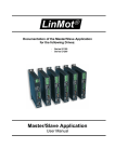
1
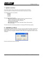
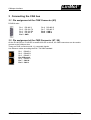
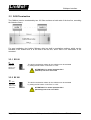
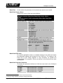
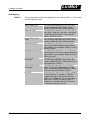
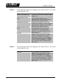
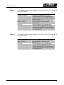
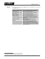
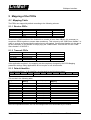
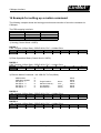
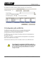
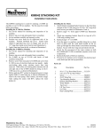
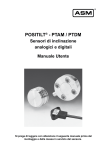
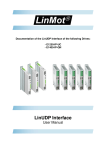
Documentation of the CANopen Interface of the following Drives: - - E1100-CO (-HC,-XC) E1100-GP (-HC, -XC) (with CANopen Firmware loaded) B1100-GP (-HC, -XC) (with CANopen Firmware loaded) CANopen Interface User Manual LinMot CANopen Interface © 2012 NTI AG This work is protected by copyright. Under the copyright laws, this publication may not be reproduced or transmitted in any form, electronic or mechanical, including photocopying, recording, microfilm, storing in an information retrieval system, not even for didactical use, or translating, in whole or in part, without the prior written consent of NTI AG. LinMot® is a registered trademark of NTI AG. Note The information in this documentation reflects the stage of development at the time of press and is therefore without obligation. NTI AG. Reserves itself the right to make changes at any time and without notice to reflect further technical advance or product improvement. Document version 3.17 / mk, May 2012 Page 2/38 User Manual CANopen Interface / 15/05/12 NTI AG / LinMot LinMot CANopen Interface Table of Content 1 SYSTEM OVERVIEW................................................................................................................... 4 2 INSTALLATION ON DRIVE..........................................................................................................4 3 CONNECTING THE CAN BUS.....................................................................................................5 3.1 PIN ASSIGNMENT OF THE COM CONNECTOR (X5)................................................................................5 3.2 PIN ASSIGNMENT OF THE CMD CONNECTOR (X7, X8).........................................................................5 3.3 CAN TERMINATION........................................................................................................................6 3.3.1 E1100.............................................................................................................................. 6 3.3.2 B1100.............................................................................................................................. 6 4 CANOPEN PARAMETERS.......................................................................................................... 7 5 MAPPING OF THE PDOS.......................................................................................................... 18 5.1 MAPPING TABLE..........................................................................................................................18 5.1.1 Receive PDOs...............................................................................................................18 5.1.2 Transmit PDOs.............................................................................................................. 18 5.1.3 Default Identifier............................................................................................................18 6 MOTOR COMMANDS................................................................................................................ 19 7 STATE MACHINE....................................................................................................................... 19 8 INTERFACE ERROR CODES....................................................................................................19 9 WARNWORD.............................................................................................................................. 19 10 OBJECT DICTIONARY............................................................................................................. 20 10.1 E1100...................................................................................................................................20 10.2 B1100...................................................................................................................................23 11 EXAMPLES FOR DRIVES OF THE E1100 SERIES.................................................................24 11.1 WRITE CURVE INTO THE DRIVE VIA CANOPEN.................................................................................24 11.2 READ CURVE FROM DRIVE VIA CANOPEN.......................................................................................27 11.3 GET UPID LIST FROM DRIVE VIA CANOPEN..................................................................................28 11.4 READ THE ERROR LOG FROM THE DRIVE........................................................................................29 12 EXAMPLES FOR DRIVES OF THE B1100 SERIES................................................................31 12.1 READ THE VALUE OF A UPID FROM A B1100 DRIVE........................................................................31 12.2 WRITE THE VALUE OF A UPID TO A B1100 DRIVE.........................................................................33 13 RESET PARAMETERS TO DEFAULT VALUES ON E1100....................................................34 14 EXAMPLE FOR SETTING UP A MOTION COMMAND............................................................35 15 CONFIGURATION WITH AN EDS FILE...................................................................................36 16 QUICK START GUIDE FOR ADVANCED USERS...................................................................37 16.1 HARDWARE-SETUP.....................................................................................................................37 16.2 CONFIGURATION OF THE DRIVE.....................................................................................................37 16.3 STARTING THE DEVICE................................................................................................................37 17 CONTACT ADDRESSES.......................................................................................................... 38 NTI AG / LinMot User Manual CANopen Interface / 15/05/12 Page 3/38 LinMot CANopen Interface 1 System overview The LinMot CANopen drives support the communication profile CiA DS301. Further information on CANopen can be found under: http://www.can-cia.de/ The following resources are available: - 3 TxPDO - 3 RxPDO - 1 TxSDO - 1 RxSDO The supported protocols include: - NMT Error Control (Node Guarding Protocol or Heartbeat Protocol) - TxPDO (Transmission type 254, 250 and 1-240) - RxPDO (Transmission type 254, 250 and 1) - SDO Upload and Download - NMT (Start, Stop, Enter PreOp, Reset Node, Reset Communication) - Boot-Up Message The baud rate can be selected by parameter or directly by BTR (bit timing register). 2 Installation on Drive For installing the CANopen firmware on the drive, start the LinMot-Talk software and press the install firmware button. Choose the file “Firmware_Buildxxxxxxxx.sct” and press “Open“. The wizard will guide you through the installation. When asking for the application software choose “CANopen”: Press ok and follow the rest of the wizard. Page 4/38 User Manual CANopen Interface / 15/05/12 NTI AG / LinMot LinMot CANopen Interface 3 Connecting the CAN bus 3.1 Pin assignment of the COM Connector (X5) D-SUB 9 male: Pin 1 Pin 2 Pin 3 Pin 4 Pin 5 RS-485 Y RS-232 TX RS-232 RX RS-485 A GND Pin 6 Pin 7 Pin 8 Pin 9 RS-485 B RS-485 Z CAN L CAN H 3.2 Pin assignment of the CMD Connector (X7, X8) On the E1100-RS-xx, E1100-DP-xx and B1100-GP-xx drives, the CMD connectors can be used to connect to the CANopen bus. These are RJ45 connectors with 1:1 connected signals. Use Ethernet cables according the EIA / TIA 568A standard. Pin 1 RS485 A Pin 2 RS485 B Pin 3 RS485 Y Pin 4/5Ground Pin 6 RS485 Z Pin 7 CAN H Pin 8 CAN L NTI AG / LinMot User Manual CANopen Interface / 15/05/12 Page 5/38 LinMot CANopen Interface 3.3 CAN Termination The CANbus must be terminated by two 120 Ohm resistors at both ends of the bus line, according the following figure: For easy installation, the LinMot CANopen drive has built in termination resistors, which can be activated, if the LinMot drive is at the end of the bus line, and if there is no termination in the connector. 3.3.1 E1100 S3 ON – OFF Interface CAN Term RS485 Term RS485/232 The built in termination resistor for the CAN bus can be activated by setting the DIP switch “CAN Term” to “ON”. ATTENTION: For normal operation S3.4 (Interface) has to be set to ON! 3.3.2 B1100 S4 ON – OFF Bootstrap CAN Term RS485 Term RS485/232 Page 6/38 The built in termination resistor for the CAN bus can be activated by setting the DIP switch “CAN Term” to “ON”. ATTENTION: For normal operation S4.4 (Bootstrap) has to be set to OFF! User Manual CANopen Interface / 15/05/12 NTI AG / LinMot LinMot CANopen Interface 4 CANopen Parameters The CANopen drives have an additional parameter tree branch (Parameters CANopen Interface), which can be configured with the distributed LinMot-Talk software. With these parameters, the CANopen behaviour can be defined. The LinMot-Talk software can be downloaded from http://www.linmot.com under the section download, software & manuals. Dis-/Enable With the Dis-/Enable parameter the LinMot drive can be run without the CANopen going online. So in a first step the system can be configured and run without any bus connection. CANopen Interface\ Dis-/Enable Disable The drive runs without CANopen. Enable The drive runs only with a CANopen connection. IMPORTANT: To activate the CANopen interface on E1100 drives, the DIP switch “Interface” at the bottom of the drive has to be set to “ON”. This is not necessary for drives of the B1100 series. NTI AG / LinMot User Manual CANopen Interface / 15/05/12 Page 7/38 LinMot Baud Rate CANopen Interface In this section the parameters for the baud rate selection are located. Baud Rate Source Select Defines the source of the baud rate definition. E1100: CANopen Interface\ Baud Rate \Baud Rate Source Select B1100: OS\Communication\ CAN Configuration\ Baud Rate\ Baud Rate Source Select By Hex Switch S1 1 E1100 only: CAN bus baud rate dependent on S1 0 = By BTR 1 = 125 kBit/s 2 = 250 kBit/s 3 = 500 kBit/s 4 = 1 Mbit/s By Parameter The CAN bus baud rate is selected by the “Baud Rate Parameter”: - 125 kBit/s [1] - 250 kBit/s [2] - 500 kBit/s [3] - 1 Mbit/s [4] By BTR CAN bus baud rate is defined according to the Bit Timing Register By DigIn 5 & 6 2 The baud rate is defined through the state of DigIn5 and DigIn6 at startup. DigIn6 is the most, DigIn5 the least significant bit. DigIn6 0 0 1 1 DigIn5 0 1 0 1 Baud Rate 125kBaud 250kBaud 500kBaud 1MBaud Baud Rate BTR Value For special applications where no standard setting for the baud rate works this parameter defines the bit timing for the CAN bus. The setting of the baud rate by Bit Timing Register is only necessary on special bus configurations: For example, if there are devices on the bus that have slow optocouplers. Baud Rate Parameter Definition The baud rate parameter defines the CAN bus baud rate for the CANopen connection. CANopen Interface\ Baud Rate\ Baud Rate Parameter Definition 125 kBit/s CAN bus baud rate = 125 kBit/s 250 kBit/s CAN bus baud rate = 250 kBit/s 500 kBit/s CAN bus baud rate = 500 kBit/s 1 Mbit/s CAN bus baud rate = 1 Mbit/s 1 2 Parameter not available on drives of the B1100 series. Parameter only available on drives of the B1100 series. Page 8/38 User Manual CANopen Interface / 15/05/12 NTI AG / LinMot LinMot CANopen Interface MACID In this section the MACID (drive number) can be configured. MACID Source Select The MACID parameter defines the source of the MACID (Node Address). E1100: CANopen Interface\ MACID\ MACID Source Select B1100: OS\ Communication\ MACID\ MACID Source Select By Hex Switch S2 E1100 only:The MACID is determined by the hex switch S2 By Hex Switches E1100 only: The MACID is determined by the S1 and S2 two hex switches S1 and S2 By Parameter The MACID is determined by parameter setting By Dig In 1 B1100 only: The MACID is defined by DigIn1 (X13.14) at power up. 0V = ID 0, 24V = ID 1 By Dig In 2..1 B1100 only: The MACID is defined by DigIn2 .. 1 (X13.2 and X13.14) at power up. DigIn2 is the most, DigIn1 the least significant bit. ( 00b = ID 0, 11b = ID 3) By Dig In 3..1 B1100 only: The MACID is defined by DigIn3 .. 1 (X13.15, X13.2 and X13.14) at power up. DigIn3 is the most, DigIn1 the least significant bit. ( 000b = ID 0, 111b = ID 7) By Dig In 4..1 B1100 only: The MACID is defined by DigIn4 .. 1 (X13.3, X13.15, X13.2 and X13.14) at power up. DigIn4 is the most, DigIn1 the least significant bit. ( 0000b = ID 0, 1111b = ID 15) By Dig In 5..1 B1100 only: The MACID is defined by DigIn5 .. 1 (X13.16, X13.3, X13.15, X13.2 and X13.14) at power up. DigIn5 is the most, DigIn1 the least significant bit. ( 00000b = ID 0, 11111b = ID 31) By Dig In 6..1 B1100 only: The MACID is defined by DigIn6 .. 1 (X13.4, X13.16, X13.3, X13.15, X13.2 and X13.14) at power up. DigIn6 is the most, DigIn1 the least significant bit. ( 000000b = ID 0, 111111b = ID 63) By Dig In 1 + B1100 only: The MACID is defined by DigIn1 Offset (X14.14) at power up plus the value of 6081h (MACID Parameter Value) as offset. 0V = ID 0, 24V = ID 1 (plus offset). By Dig In 2..1 + B1100 only: The MACID is defined by DigIn2 .. 1 Offset (X14.2 and X14.14) at power up plus the value of 6081h (MACID Parameter Value) as offset. DigIn2 is the most, DigIn1 the least significant bit. ( 00b = ID 0, 11b = ID 3 (plus offset)) By Dig In 3..1 + B1100 only: The MACID is defined by DigIn3 .. 1 Offset (X14.15, X14.2 and X14.14) at power up plus the value of 6081h (MACID Parameter Value) as offset. DigIn3 is the most, DigIn1 the least significant bit. ( 000b = ID 0, 111b = ID 7 (plus offset)) NTI AG / LinMot User Manual CANopen Interface / 15/05/12 Page 9/38 LinMot CANopen Interface By Dig In 4..1 + Offset By Dig In 5..1 + Offset By Dig In 6..1 + Offset Parameter Value B1100 only: The MACID is defined by DigIn4 .. 1 (X14.3, X14.15, X14.2 and X14.14) at power up plus the value of 6081h (MACID Parameter Value) as offset. DigIn4 is the most, DigIn1 the least significant bit. ( 0000b = ID 0, 1111b = ID 15 (plus offset)) B1100 only: The MACID is defined by DigIn5 .. 1 (X14.16, X14.3, X14.15, X14.2 and X14.14) at power up plus the value of 6081h (MACID Parameter Value) as offset. DigIn5 is the most, DigIn1 the least significant bit. ( 00000b = ID 0, 11111b = ID 31 (plus offset)) B1100 only: The MACID is defined by DigIn6 .. 1 (X14.4, X14.16, X14.3, X14.15, X14.2 and X14.14) at power up plus the value of 6081h (MACID Parameter Value) as offset. DigIn6 is the most, DigIn1 the least significant bit. ( 000000b = ID 0, 111111b = ID 63 (plus offset)) The MACID, when “Parameter” is selected MACID Parameter Value Is the ID, when “By Parameter” is selected as source. E1100 With the default settings, the MAC-ID and the baud rate are selected by the two rotary hex switches S1 and S2. B1100 With the default settings, the MAC-ID and the baud rate are both selected by Parameter. The default values are 500kBit/s as baud rate and 63 (3Fh) for the MACID. Page 10/38 User Manual CANopen Interface / 15/05/12 NTI AG / LinMot LinMot CANopen Interface PDO Mapping TxPDO 1 These parameters define the mapping of the transmit PDO 1. Four words can be mapped in total. CANopen Interface\ PDO Mapping\ TxPDO 1 Status Word [1W] If this Boolean parameter is set, the status word is transmitted with TxPDO 1 (see variable 1D51h (E1100) / 6061h (B1100)). State Var [1W] If this Boolean parameter is set, the state var (high byte = state no. / low byte = sub state) is transmitted with TxPDO 1 (see variable 1B62h / 6968h (B1100)). Logged Error Code If this Boolean parameter is set, the logged [1W] error code is transmitted with TxPDO 1 (see variable 1D96h (E1100) / 6976h (B1100)). Warn Word [1W] If this Boolean parameter is set, the warn word (= bit coded warnings) is transmitted with TxPDO 1 (see variable 1D8Eh (E1100) / 6068h (B1100)). Demand Current [1W] If this Boolean parameter is set, the demand current value (= motor current) is transmitted with TxPDO 1 (see variable 1B93h (E1100) / E9E7h (B1100)). Actual Position low If this Boolean parameter is set, the lower 16 word [1W] bit of the actual position (32 bit value, see variable 1B8Dh (E1100) / F4D9h (B1100)) is transmitted with TxPDO 1. Actual Position high If this Boolean parameter is set, then the word [1W] higher 16 bit of the actual position (32 bit value, see variable 1B8Dh (E1100) / F4D9h (B1100)) is transmitted with TxPDO 1. By UPID This parameter can be used for free mapping of any parameter or variable to TxPDO 1 (mapping through Unique Parameter ID = UPID, 0 = no mapping). The corresponding data size in TxPDO 1 is either 1 word, if parameter or variable type is 16 bit or less, or 2 words, if the type is 32 bit. NTI AG / LinMot User Manual CANopen Interface / 15/05/12 Page 11/38 LinMot TxPDO 2 CANopen Interface These parameters define the mapping of the transmit PDO 2. Four words can be mapped in total. CANopen Interface\ PDO Mapping\ TxPDO 2 Motion Cmd Status [1W] Feedback of the motion command header (toggle, etc?) Actual Position 16 Bit If this Boolean parameter is set, the actual [1W] motor position in 16 bit format is transmitted with TxPDO 2 (see variable 1B95h (E1100) / E9A5h (B1100)). Demand Current [1W] If this Boolean parameter is set, the demand current value (= motor current) is transmitted with TxPDO 2 (see variable 1B93h (E1100) / E9E7h (B1100)). Demand Position 16 Bit If this Boolean parameter is set, the [1W] demand position in 16 bit format is transmitted with TxPDO 2 (position setpoint, see variable 1B94h (E1100) / E9A4h (B1100)). By UPID This parameter can be used for free mapping of any parameter or variable to TxPDO 2 (mapping through Unique Parameter ID = UPID, 0 = no mapping). The corresponding data size in TxPDO 2 is either 1 Word, if parameter or variable type is 16 bit or less, or 2 Words, if the type is 32 bit. TxPDO 3 These parameters define the mapping of the transmit PDO 3. Four words can be mapped in total. CANopen Interface\ PDO Mapping\ TxPDO 3 By UPID This parameter can be used for free mapping of any parameter or variable to TxPDO 3 (mapping through Unique Parameter ID = UPID, 0 = no mapping). The corresponding data size in TxPDO 3 is either 1 Word, if parameter or variable type is 16 bit or less, or 2 Words, if the type is 32 bit. Page 12/38 User Manual CANopen Interface / 15/05/12 NTI AG / LinMot LinMot CANopen Interface RxPDO 1 These parameters define the mapping of the receive PDO 1. Four words can be mapped in total. CANopen Interface\ PDO Mapping\ RxPDO 1 Control Word [1W] If this Boolean parameter is set, the control word has to be transmitted with RxPDO 1 (see variable 1D52h (E1100) / 6062h (B1100)). Motion Cmd Header + Par Motion command interface (Header and Byte 0..3 [3W] the first 4 bytes of the command parameters). By UPID For free mapping, every parameter or variable can be mapped by its UPID (Unique Parameter ID). The size is either 1 word, if type is 16 bit or less, or 2 words, if the type is 32 bit. RxPDO 2 These parameters define the mapping of the receive PDO 2. Four words can be mapped in total. CANopen Interface\ PDO Mapping\ RxPDO 2 Motion Cmd Header + Par Motion command interface (header and Byte 0..5 [4W] the first 6 bytes of the command parameters) By UPID For free mapping, every parameter or variable can be mapped by its UPID (Unique Parameter ID). The size is either 1 word, if type is 16 bit or less, or 2 words, if the type is 32 bit. NTI AG / LinMot User Manual CANopen Interface / 15/05/12 Page 13/38 LinMot RxPDO 3 CANopen Interface These parameters define the mapping of the receive PDO 3. Four words can be mapped in total. CANopen Interface\ PDO Mapping\ RxPDO 3 CMD Slave Header + Par Command interface (slave header and Byte 6..7 [2W] byte 6..7 of the parameters) CMD Slave Header + Par Command interface (slave header and Byte 6..9 [3W] byte 6..9 of the parameters) CMD Slave Header + Par Command interface (slave header and Byte 6..11 [4W] byte 6..11 of the parameters) 3 Direct Par X [1W] Direct parameter channel for setting live parameters during runtime (only 16 bit parameters). Direct Par X UPID 4 UPID (Unique Parameter ID) of the selected parameter By UPID For free mapping, every parameter or variable can be mapped by its UPID (Unique Parameter ID). The size is either 1 word, if type is 16 bit or less, or 2 words, if the type is 32 bit. 3 4 Parameter not available on drives of the B1100 series. Parameter not available on drives of the B1100 series. Page 14/38 User Manual CANopen Interface / 15/05/12 NTI AG / LinMot LinMot CANopen Interface PDO Configuration TxPDO 1..3 These parameters define the bus parameters of the transmit PDO 1..3. TxPDO 1..3 Enable Selector for enabling/disabling the transmit PDO 1..3. CANopen Interface\ PDO Configuration\ TxPDO 1..3\ TxPDO 1..3 Enable Disable The PDO is deactivated Enable The PDO is activated Transmission Type This defines the transmission type according to DS 301. Default Value is 254 (Asynchronous with inhibit Time). Types 1-240 (cyclic synchronous) are supported as well. If any of the TxPDOs has a synchronous transmission mode set, all RxPDOs are automatically evaluated synchronously. The transmission type 250 is LinMot specific (it is reserved according to DS301). If transmission Type 250 is selected, the Transmit PDO is sent immediately after reception of the corresponding Receive PDO (TxPDO 1 corresponds to RxPDO 1). It can be used to realize a simple Poll-Request / Poll-Respond type bus structure. The “Legacy Sync WatchDog” feature can be used for monitoring (RxPDO 1 takes the function of the Sync). Inhibit Time Defines the minimal time between two send events. Event Time Defines the maximum time between two send events. RxPDO 1..3 These parameters define the bus parameters of the receive PDO 1..3. CANopen Interface\ PDO Configuration\ RxPDO 1..3 Disable The PDO is deactivated Enable The PDO is activated CANopen Interface\ PDO Configuration\ RxPDO 3 COB ID 0 = Default Mapping for RxPDO 3 COB ID xx= COB ID for RxPDO 3 (manual configuration) NTI AG / LinMot User Manual CANopen Interface / 15/05/12 Page 15/38 LinMot CANopen Interface Evaluate RxPDOs on SYNC with all TxPDOs asynchronous These parameters defines the evaluation of RxPDOs on SYNC-messages. CANopen Interface\ PDO Configuration\ Evaluate RxPDOs on SYNC with all TxPDOs asynchronous Disable RxPDOs are not synchronously evaluated Enable RxPDOs are synchronously evaluated This parameter is only in effect if all TxPDOs are configured for asynchronous transmission. If any of the TxPDOs has a synchronous transmission mode set, all RxPDOs are automatically evaluated synchronously. This setting can be used if one wants to send RxPDOs synchronously (e.g. for streaming-modes) but the response TxPDOs should only be transmitted asynchronously. NMT Error Control Nodeguarding Protocol Directory for configuring the nodeguarding. Nodeguarding Enable Enable/Disable the node guarding feature. CANopen Interface\ NMT Error Control\ Node Guarding Protocol\ Node Guarding Enable Disable The Node Guarding Protocol is deactivated. Enable The Node Guarding Protocol is activated. Guard Time The Guard time, when Node Guarding is activated. Guard Time The Guard time, when Node Guarding is activated. Heartbeat Protocol These parameters configure the Heartbeat Protocol. CANopen Interface\ NMT Error Control\ Heartbeat Protocol Produce Cyclic Heartbeat is produced. Consume Cyclic Heartbeat is consumed Producer Time Cycle Time for producing Heartbeat Consumer Time Guarding Time for consumed Heartbeat Consumed Node ID of the Master Node ID (Master) Page 16/38 User Manual CANopen Interface / 15/05/12 NTI AG / LinMot LinMot CANopen Interface Legacy Sync Watchdog These parameters configure the legacy watchdog of the Sync Telegram. This can be used together with Heartbeat or Node Guarding (CO firmware Version ≥3.8). Watchdog Enable Enabling/Disabling the legacy sync watchdog feature. CANopen Interface\ NMT Error Control\ Legacy Sync Watchdog\ Watchdog Enable Disable The Sync Watchdog is deactivated. Enable The Sync Watchdog is activated. Sync Cycle The expected Sync Cycle Time. Time Sync Cycle Time The Sync cycle is monitored with 1.5* Sync Cycle Time. This means that the real expected Sync Cycle Time can be configured here. Only one NMT Error Control Protocol should be activated. NTI AG / LinMot User Manual CANopen Interface / 15/05/12 Page 17/38 LinMot CANopen Interface 5 Mapping of the PDOs 5.1 Mapping Table The PDOs are mapped by default according to the following scheme: 5.1.1 Receive PDOs RxPDO 1 Control Word RxPDO 2 CMD Header Par 1 Par 2 Par 3 RxPDO 3 CMD Slave Header Par 4 Direct Par Channel 1 Because the CMD interface of the LinMot drive consists of more than 8 Bytes, it’s necessary to couple two PDOs together to ensure data consistency. This is done by the “CMD Slave Header”. In order to execute a command both headers have to be toggled. On the slave Header only the last 4 bit are evaluated, so it’s possible to simply copy the “CMD Header” from RxPDO 2 to the “CMD Slave Header” of RxPDO 3. 5.1.2 Transmit PDOs TxPDO 1 Status Word Run State Error Code Warn Word TxPDO 2 CMD Status Actual Position Actual Current Actual SetPosition TxPDO 3 If the application requires it, the mapping can be completely changed by the PDO Mapping parameter settings. Many applications do not require to use all resources. 5.1.3 Default Identifier The default identifiers (11 Bit identifier) are allocated by the following scheme: 10 9 Function Code 8 7 6 5 Node ID 4 3 2 1 0 This results in the following table: Object COB ID (hex) NMT SYNC Function Code (binary) 0000 0001 00h 80h Object for Comm. Parameter / Mapping -/1005h / 1006h Emergency TxPDO 1 TxPDO 2 TxPDO 3 RxPDO 1 RxPDO 2 RxPDO 3 TxSDO RxSDO 0001 0011 0101 0111 0100 0110 1000 1011 1100 81h – FFh 181h – 1FFh 281h – 2FFh 381h – 3FFh 201h – 27Fh 301h – 37Fh 401h – 47Fh 581h – 5FFh 601h – 67Fh -/1800h 1801h 1802h 1400h 1401h 1402h -/-/- In the Pre-Operational state, this can be changed with SDO downloads by the master. Page 18/38 User Manual CANopen Interface / 15/05/12 NTI AG / LinMot LinMot CANopen Interface 6 Motor Commands Please refer to “Usermanual Motion Control Software” 7 State Machine Please refer to “Usermanual Motion Control Software” 8 Interface Error Codes Please refer to “Usermanual Motion Control Software” for the Error Codes of the MC Software. The CANopen Interface has the following additional Error Codes: Error Code Hexadecimal C1h C2h C3h C4h C5h C6h C7h C8h C9h CAh CBh CCh CDh CEh CFh D0h D1h D2h D3h D4h D5h D6h D7h D8h D9h DAh DBh DCh Error Description The drive is not compatible with CANopen The configured ID is not valid (switches or parameter) CANopen Error: Data out of Range CANopen Error: Invalid Command CANopen Error: Bus error CANopen Error: general Bus error CANopen Error: Bus error, stuff error CANopen Error: Bus error, form error CANopen Error: Bus error, ack error CANopen Error: Bus error, bit 1 error CANopen Error: Bus error, bit 0 error CANopen Error: Bus error, CRC error CANopen Error: Bus error, guard timeout CANopen Error: Invalid UPID configured on Direct Par 1 CANopen Error: Invalid UPID configured on Direct Par 2 CANopen Error: Error: Invalid ID by Hex Switch S1 CANopen Error: Invalid Mapping in TxPDO 1 CANopen Error: Invalid Mapping in TxPDO 2 CANopen Error: Invalid Mapping in TxPDO 3 CANopen Error: Invalid Mapping in RxPDO 1 CANopen Error: Invalid Mapping in RxPDO 2 CANopen Error: Invalid Mapping in RxPDO 3 CANopen Error: Invalid UPID in TxPDO 1 Mapping CANopen Error: Invalid UPID in TxPDO 2 Mapping CANopen Error: Invalid UPID in TxPDO 3 Mapping CANopen Error: Invalid UPID in RxPDO 1 Mapping CANopen Error: Invalid UPID in RxPDO 2 Mapping CANopen Error: Invalid UPID in RxPDO 3 Mapping 9 WarnWord Please refer to “Usermanual Motion Control Software” NTI AG / LinMot User Manual CANopen Interface / 15/05/12 Page 19/38 LinMot CANopen Interface 10 Object Dictionary 10.1 E1100 Index 0001h– 001Fh 0020h Sub-Index Description Data Types Data Type DEFTYPE Communication Parameter Number of entries COB-ID Transmission type Inhibit time Reserved Event timer DEFSTRUCT UI8 UI32 UI8 UI16 UI8 UI16 Device Type Error register Manufacturer Device Name UI32 UI8 Visible String 0h 1h 2h Idendity Object Number of Entries Vendor ID Product Code Record UI8 UI32 UI32 3h 4h Revision Number Serial Number UI32 UI32 UI32 00h 01h 02h 03h 04h 05h 06h LinMot Parameters Index = 2000h + UPID Number of Entries RAM Value ROM Value Min Value Max Value Default Value RAM/ROM Write 07h Set ROM to default (OS) 08h Set ROM to default (MC) 09h Set ROM to default (Interface) 0h 1h 2h 3h 4h 5h 1000h 1001h 1008h 1018h 2000h -5FFFh Page 20/38 SI32 SI32 SI32 SI32 SI32 SI32 User Manual CANopen Interface / 15/05/12 Value 0 4 ASCII characters, which contain the last 4 characters of the article number. 4 0000 0156h 4 ASCII characters, which contain the last 4 characters of the article number. Serial Number UI32 encoded RAM Value (rw) ROM Value (rw) Minimal Value (ro) Maximal Value (ro) Default Value (ro) RAM and ROM value can be written with the same value (wo) Write anything to 2000h sub 7 to set all parameters of the OS to default values (wo). This command needs about 0.5s to finish. Write anything to 2000h sub 8 to set all parameters of the MC Sw to default values (wo). This command needs about 2s to finish. Write anything to 2000h sub 9 to set all parameters of the CANopen Interface to default values (wo). This command needs about 0.5 s to finish. NTI AG / LinMot LinMot CANopen Interface 0Ah Set ROM to default (Application) 0Bh Reset drive 20h 21h 22h 23h Start Getting UPID List Get Next UPID List item Start Getting Modified UPID List Get Next Modified UPID List item Stop MC and Application Software (for Flash access) 35h 36h Start MC and Application Software 40h Curve Service: Save to Flash 41h Curve Service: Delete all Curves (RAM) 42h Curve Service: Poll Flash 50h 51h 62h 70h 71h 72h 73h 74h 80h Curve Service: Add Curve Curve Service: Add Curve Info Block Curve Service: Add Curve Data Curve Service: Add Curve Data (32 Bit) Curve Service: Add Curve Info Block (32 Bit) Curve Service: Get Curve Curve Service: Get Curve Info Block Curve Service: Get Curve Data Get Error Log Entry Counter Get Error Log Entry Error Code Get Error Log Entry Time low Get Error Log Entry Time high Get Error Code Text Stringlet CT: Save to Flash 80h CT: Poll Flash 81h CT: Delete all Entries (RAM) 82h CT: Delete Entry (Entry Nr.) 52h 53h 54h 60h 61h NTI AG / LinMot User Manual CANopen Interface / 15/05/12 Write anything to 2000h sub Ah to set all parameters of the Application to default values (wo) Write anything to 2000h sub Bh to reset the drive (wo) See chapter 11.3 See chapter 11.3 See chapter 11.3 See chapter 11.3 Write anything to 2000h sub 35h to stop the MC and Application SW (wo) Write anything to 2000h sub 36h to start the MC and Application SW (wo) Write anything to 2000h sub 40h to save the curves from the RAM into the Flash ROM (wo) Write anything to 2000h sub 41h to Delete all Curves in the RAM (wo) Read anything from 2000h sub 42h to get the Flash state (r) See chapter 11 See chapter 11 See chapter 11 See chapter 11 See chapter 11 See chapter 11 See chapter 11 See chapter 11 See chapter 11.4 See chapter 11.4 See chapter 11.4 See chapter 11.4 See chapter 11.4 Write anything to 2000h sub 80h to save the Command Table from the RAM into the Flash ROM (w) Read anything from 2000h sub 80h to get the Flash state (r) Write anything to 2000h sub 81h to delete the complete Command Table in the RAM (wo) Write anything to 2000h + Entry Nr. Sub 82h to delete entry in the RAM Page 21/38 LinMot CANopen Interface 83h CT: Write Entry (Entry Nr.) 84h CT: Write Entry Data 85h CT: Get Entry (Entry Nr.) 86h 87h 88h 89h 8Ah CT: Get Entry Data CT: Get Entry List (Entry 0..31) CT: Get Entry List (Entry 32..63) CT: Get Entry List (Entry 64..95) CT: Get Entry List (Entry 96..127) CT: Get Entry List (Entry 128..159) CT: Get Entry List (Entry 160..191) CT: Get Entry List (Entry 192..223) CT: Get Entry List (Entry 224..255) 8Bh 8Ch 8Dh 8Eh Page 22/38 User Manual CANopen Interface / 15/05/12 Write block size to 2000h + Entry Nr. Sub 83h to prepare entry in the RAM Write 2 Byte Data to 2000h + Entry Nr. Sub 84h, until block size has reached (the entry will be activated at this time) Read the block size of 2000h + Entry Nr. Sub 85h. Read 2 byte data Read Bitfield (0=present) Read Bitfield (0=present) Read Bitfield (0=present) Read Bitfield (0=present) Read Bitfield (0=present) Read Bitfield (0=present) Read Bitfield (0=present) Read Bitfield (0=present) NTI AG / LinMot LinMot CANopen Interface 10.2 B1100 Index 0001h– 001Fh 0020h Sub-Index Description Data Types Data Type DEFTYPE Communication Parameter Number of entries COB-ID Transmission type Inhibit time Reserved Event timer DEFSTRUCT UI8 UI32 UI8 UI16 UI8 UI16 Device Type Error register Manufacturer Device Name UI32 UI8 Visible String 0h 1h Idendity Object Number of Entries Vendor ID Record UI8 UI32 LinMot Parameters Number of Entries RAM Value of current UPID ROM Value of current UPID UI32 00h 01h 02h 0Bh Reset Drive Write anything to 2000h sub Bh to reset the drive (wo) C0h Update Current UPID Write the current UPID the drive uses to get RAM and ROM values to the drive (wo) 0h 1h 2h 3h 4h 5h 1000h 1001h 1008h 1018h 2000h NTI AG / LinMot SI32 SI32 User Manual CANopen Interface / 15/05/12 Value 0 4 ASCII Characters, which consist of the last 4 characters of the article number 1 0000 0156h for LinMot RAM Value (rw) ROM Value (rw) Page 23/38 LinMot CANopen Interface 11 Examples for Drives of the E1100 series 11.1 Write Curve into the Drive via CANopen Add curve A curve with the ID “CurveID” will be created. If a curve with the same ID already exists, an error will be generated. Index 2000h + CurveID Sub-Index 50h Data InfoBlockSize (2 bytes) + DataBlockSize (2 bytes) Result 00h: No error D4h: Curve already exist Example LinMot MACID = 1 CuveID = 1 InfoBlockSize = 70 (0046h) DataBlockSize = 164 (00A4h) Index = 2001h Sub-Index = 50h CAN Telegram (8 Byte Data), COB-ID 601, PLC -> LinMot drive: Index Data 23h 01h 20h Sub-Index 50h Info Block Size 46h 00h Data Block Size A4h 00h Response: (8 Byte Data), COB-ID 581, LinMot drive -> PLC: Index Data 60h 01h 20h Sub-Index 50h Unused Data 00h 00h Result 00h 00h Add Curve Info Block Index 2000h + CurveID Sub-Index 51h Data Unused data (2 bytes) Info Block data (2 bytes) Result 04h: Info Block is not finished 00h: Info Block is finished D0h: Error: Info Block was already finished Example Index = 2001h Sub-Index = 51h Data = 0046h CAN Telegram (8 Byte Data), COB-ID 601, PLC -> LinMot drive: Index Data 23h 01h 20h Sub-Index 51h Unused Data 00h 00h Info Block Data 46h 00h Response: (8 Byte Data), COB-ID 581, LinMot drive -> PLC: Index Data Page 24/38 60h 01h 20h Sub-Index 51h Unused Data 00h 00h User Manual CANopen Interface / 15/05/12 Result 04h 00h NTI AG / LinMot LinMot CANopen Interface Add Curve Info Block 32Bit Index 2000h + CurveID Sub-Index 54h Data Info Block data (4 bytes) Result 04h: Info Block is not finished 00h: Info Block is finished D0h: Error: Info Block was already finished Example Index = 2001h Sub-Index = 51h Data = 0046h CAN Telegram (8 Byte Data), COB-ID 601, PLC -> LinMot Drive: Index Data 23h 01h 20h Sub-Index 51h 00h Info Block Data 00h 00h 00h Response: (8 Byte Data), COB-ID 581, LinMot Drive -> PLC: Index Data 60h 01h 20h Sub-Index 51h Unused Data 00h 00h Result 04h 00h Add Curve Data Index 2000h + CurveID Sub-Index 52h Data Unused data (2 bytes) Data Block data (2 bytes) Result 04h: Data Block is not finished 00h: Data Block is finished D0h: Error: Data Block was already finished Example Index = 2001h Sub-Index = 52h Data = 2710h CAN Telegram (8 Byte Data), COB-ID 601, PLC -> LinMot Drive: Index Data 23h 01h 20h Sub-Index 52h Unused Data 00h 00h Data Block Data 10h 27h Response: (8 Byte Data), COB-ID 581, LinMot Drive -> PLC: Index Data 60h NTI AG / LinMot 01h 20h Sub-Index 52h Unused Data 00h 00h User Manual CANopen Interface / 15/05/12 Result 04h 00h Page 25/38 LinMot CANopen Interface Add Curve Data 32 Bit Index 2000h + CurveID Sub-Index 53h Data Data Block data (4 bytes) Result 04h: Data Block is not finished 00h: Data Block is finished D0h: Error: Data Block was already finished Example Index = 2001h Sub-Index = 53h Data = 01312D00h CAN Telegram (8 Byte Data), COB-ID 601, PLC -> LinMot Drive: Index Data 23h 01h 20h Sub-Index 53h 00h Data Block Data 2Dh 31h 01h Response: (8 Byte Data), COB-ID 581, LinMot Drive -> PLC: Index Data Page 26/38 60h 01h 20h Sub-Index 53h Unused Data 00h 00h User Manual CANopen Interface / 15/05/12 Result 04h 00h NTI AG / LinMot LinMot CANopen Interface 11.2 Read curve from Drive via CANopen Get curve Index 2000h + CurveID Sub-Index 60h Example CuveID = 1 Result = 00 46 1401 -> Result = D4 xx xxxx -> Data - Result (4 bytes) 00h: Curve exists D4h: Curve does not exist 00: Curve exists 46: InfoBlock Size bytes 0114: DataBlock Size bytes D4: Curve does not exist Get Curve Info Block Index 2000h + CurveID Sub-Index 61h Data - Result (4 bytes) 04h: Info Block is not finished 00h: Info Block is finished D0h: Error: Info Block was already finished Sub-Index 62h Data - Result (4 bytes) 04h: Data Block is not finished 00h: Data Block is finished D0h: Error: Data Block was already finished Get Curve Data Index 2000h + CurveID NTI AG / LinMot User Manual CANopen Interface / 15/05/12 Page 27/38 LinMot CANopen Interface 11.3 Get UPID List from Drive via CANopen Start getting UPID List Index 2000h Example Index = 2000h Sub-Index = 20h Start UPID 1000h Sub-Index 20h Data Start UPID (2 bytes) Result 00h: OK CAN Telegram (8 Byte Data), COB-ID 601, PLC -> LinMot Drive: Index Data 23h 00h Sub-Index 20h 20h Unused Data 00h 00h Start UPID 00h 10h Response: (8 Byte Data), COB-ID 581, LinMot Drive -> PLC: Index Data 60h 00h Sub-Index 20h 20h Unused Data 00h 00h Result 04h 00h Unused Data 00h 00h 00h Get Next UPID List Item Index 2000h Sub-Index 21h Data Address Usage Result UPID found When the end of the list is reached the UPID FFFFh is sent. Example Index = 2000h Sub-Index = 21h UPID found = 1004h Address Usage = 000Dh CAN Telegram (8 Byte Data), COB-ID 601, PLC -> LinMot Drive: Index Data 40h 00h Sub-Index 21h 20h 00h Response: (8 Byte Data), COB-ID 581, LinMot Drive -> PLC: Index Data 43h 00h Sub-Index 21h 20h Address Usage 0Dh 00h UPID found 04h 10h Life Parameter 11 10 9 8 7 6 5 4 RAM Read 12 RAM Write 13 ROM Read 14 ROM Write 15 calculationNot used for Hash Address Usage: 3 2 1 0 The commands for getting the modified UPID List are used the same way. Page 28/38 User Manual CANopen Interface / 15/05/12 NTI AG / LinMot LinMot CANopen Interface 11.4 Read the Error Log from the Drive Get Error Log Entry Counter Index 2000h Sub-Index 70h Data - Result Number of Logged Errors Number of Occurred Errors Example Index = 2000h Sub-Index = 70h Number of Logged Errors = 0015h Number of Occurred Errors = 0034h CAN Telegram (8 Byte Data), COB-ID 601, PLC -> LinMot Drive: Index Data 40h 00h 20h Sub-Index 70h 00h Unused Data 00h 00h 00h Response: (8 Byte Data), COB-ID 581, LinMot Drive -> PLC: Index Data 43h 00h 20h Sub-Index 70h Nr. of Logged Err 15h 00h Nr. Of Occurred Err 34h 00h Get Error Log Entry Error Code Index Sub-Index Data 2000h + Entry Nr. 71h Example Index = 2005h Sub-Index = 71h Error Code of entry 5 = 64h (Cfg. Err: No Motor defined) Result Error Code CAN Telegram (8 Byte Data), COB-ID 601, PLC -> LinMot Drive: Index Data 40h 05h 20h Sub-Index 71h 00h Unused Data 00h 00h 00h Response: (8 Byte Data), COB-ID 581, LinMot Drive -> PLC: Index Data 43h 05h 20h Sub-Index 71h Unused Data 00h 00h Error Code 64h 00h Get Error Log Entry Time Low Index Sub-Index Data 2000h + Entry Nr. 72h Example Index = 2005h Sub-Index = 72h Time Low of entry 5 = 28C1h (=10433ms=10.433s) Result Time Low (milliseconds) CAN Telegram (8 Byte Data), COB-ID 601, PLC -> LinMot Drive: Index Data 40h NTI AG / LinMot 05h 20h Sub-Index 72h 00h User Manual CANopen Interface / 15/05/12 Unused Data 00h 00h 00h Page 29/38 LinMot CANopen Interface Response: (8 Byte Data), COB-ID 581, LinMot Drive -> PLC: Index Data 43h 05h Sub-Index 72h 20h Time Low C1h 28h Time Mid Low 00h 00h Get Error Log Entry Time High Index Sub-Index Data 2000h + Entry Nr. 73h Example Index = 2005h Sub-Index = 73h Time High of entry 5 = 0398h (=920 hours) Result Time High (hours) CAN Telegram (8 Byte Data), COB-ID 601, PLC -> LinMot Drive: Index Data 40h 05h Sub-Index 73h 20h 00h Unused Data 00h 00h 00h Response: (8 Byte Data), COB-ID 581, LinMot Drive -> PLC: Index Data 43h 05h Sub-Index 73h 20h Time Mid High 98h 03h Time High 00h 00h The Time of an entry consists of 32Bit hours and 32Bit milliseconds. Get Error Code Text Stringlet Index 2000h + Error Code. Sub-Index 74h + (Stringlet No. 0..7) Data - Result 4 Bytes of Error Code Text Example Index = 2064h (Error Code 64h = „Cfg Err: No Motor Defined“) Sub-Index = 74h Character 0..3 = 43 66 67 20 = “Cfg “ CAN Telegram (8 Byte Data), COB-ID 601, PLC -> LinMot Drive: Index Data 40h 64h 20h Sub-Index 74h 00h Unused Data 00h 00h 00h Response: (8 Byte Data), COB-ID 581, LinMot Drive -> PLC: Index Data 43h 64h 20h Sub-Index 74h Char 0 43h Char 1 66h Char 2 67h Char 3 20h The Time of an entry consists of 32Bit hours and 32Bit milliseconds. Page 30/38 User Manual CANopen Interface / 15/05/12 NTI AG / LinMot LinMot CANopen Interface 12 Examples for Drives of the B1100 series Read or Write the Value of a UPID of the Drive via CANopen Reading or writing the value of a UPID from/to the drive, has to be performed in two separate steps. First the UPID on which to operate (i.e. read or write) has to be sent to the drive via an SDO-command (index 2000h and sub index C0h). This UPID will be referred to as the actual UPID from here on. After this is done the value of the actual UPID can be read or written by other SDOCommands (index 2000h and sub indices 01h and 02h). 1 PLC read / write actual UPID B1100 Current UPID read / write value Value of Current UPID 2 12.1 Read the value of a UPID from a B1100 Drive 1. Write the actual UPID which the Drive uses Index 2000h Sub-Index C0h Data UPID Unused - Example Index = 2000h Sub-Index = C0h UPID = E9E7h (UPID of the Demand Current) CAN Telegram (8 Byte Data), COB-ID 601h, PLC -> LinMot Drive: Index Data 23h 00h 20h Sub-Index C0h UPID E7h E9h Unused Data 00h 00h Response: (8 Byte Data), COB-ID 581h, LinMot Drive -> PLC: Index Data 60h NTI AG / LinMot 00h 20h Sub-Index C0h 00h User Manual CANopen Interface / 15/05/12 Unused Data 00h 00h 00h Page 31/38 LinMot CANopen Interface 2. Read the value of the actual UPID from the Drive Index 2000h Sub-Index 01h Result Value of the actual UPID Example Index = 2000h Sub-Index = 01h (Value is read from the RAM) CAN Telegram (8 Byte Data), COB-ID 601h, PLC -> LinMot Drive: Index Data 40h 00h 20h Sub-Index 01h Unused Data 00h 00h 00h UPID Parameter Value FEh FFh FFh 00h Response: (8 Byte Data), COB-ID 581h, LinMot Drive -> PLC: Index Data 43h 00h 20h Returned value of the Demand Current Page 32/38 Sub-Index 01h DCh = FFFFFEDCh = -292 Dec. (Scale 0.001 A) = -0.292 A User Manual CANopen Interface / 15/05/12 NTI AG / LinMot LinMot CANopen Interface 12.2 Write the Value of a UPID to a B1100 Drive 1. Write the actual UPID which the Drive uses Index 2000h Sub-Index C0h Data UPID Unused - Example Index = 2000h Sub-Index = C0h UPID = E19Ch (UPID of the Maximal Current) CAN Telegram (8 Byte Data), COB-ID 601h, PLC -> LinMot Drive: Index Data 23h 00h 20h Sub-Index C0h UPID 9Ch E1h Unused Data 00h 00h Response: (8 Byte Data), COB-ID 581h, LinMot Drive -> PLC: Index Data 60h 00h 20h Sub-Index C0h 00h Unused Data 00h 00h 00h 2. Write the desired value of the actual UPID to the Drive Index 2000h Sub-Index 01h Data Desired value of the actual UPID Example Index = 2000h Sub-Index = 01h (The value is written to the RAM) Desired value of the Maximal Current = 0BB8h = 3000 Dec. (Scale 0.001 A) =3A CAN Telegram (8 Byte Data), COB-ID 601h, PLC -> LinMot Drive: Index Data 23h 00h 20h Sub-Index 01h Desired UPID Parameter Value B8h 0Bh 00h 00h Response: (8 Byte Data), COB-ID 581h, LinMot Drive -> PLC: Index Data 60h NTI AG / LinMot 00h 20h Sub-Index 01h 00h Unused Data 00h 00h User Manual CANopen Interface / 15/05/12 00h Page 33/38 LinMot CANopen Interface 13 Reset Parameters to default values on E1100 There are three options to reset the parameters of a LinMot E1100 drive to default values: 1) 2) 3) By manipulating the two rotary hex switches: - Power Off the drive - Set the switches to FF - Power On the drive - Set the switches to 00 - Wait for 10 s - Power Off the drive By writing Index 2000h sub-index 7h, 8h, 9h, Ah of the Object dictionary. After changing the ROM values, a Reset should be performed either by a NMT Reset command or by Power OFF and ON the drive. Reinstall the firmware will always reset the parameters to default values Page 34/38 User Manual CANopen Interface / 15/05/12 NTI AG / LinMot LinMot CANopen Interface 14 Example for setting up a motion command The following example shows the homing procedure and execution of a motion command via CANopen: The PDO mapping is default: RxPDO 1 Control Word RxPDO 2 CMD Header Par Byte 0…1 Par Byte 2…3 Par Byte 4…5 RxPDO 3 CMD Slave Header Par Byte 6…7 1) Homing (Control Word = 083Fh) RxPDO 1 CAN Telegram (2 Byte Data), COB-ID 201h, PLC -> LinMot Drive: Byte Nr. Data 0 3Fh 1 08h 2 xx 3 xx 4 xx 5 xx 6 xx 7 xx 5 xx 6 xx 7 xx 2) Enter Operational State (Control Word = 003Fh) RxPDO 1 CAN Telegram (2 Byte Data), COB-ID 201h, PLC -> LinMot Drive: Byte Nr. Data 0 3Fh 1 00h 2 xx 3 xx 4 xx 3) Execute Motion Command : VAI 16Bit Go To Pos (090xh) CMD Header CMD Slave Header Par Byte 0…1 Par Byte 2…3 Par Byte 4…5 Par Byte 6…7 Target Position : Maximal Velocity : Acceleration : Deceleration : 0901h 0901h 01F4h 03E8h 0064h 0064h 50mm 1m/s 10m/s2 10m/s2 RxPDO 2 CAN Telegram (8 Byte Data), COB-ID 301h, PLC -> LinMot Drive: Byte Nr. Data 0 01h 1 09h 2 F4h 3 01h 4 E8h 5 03h 6 64h 7 00h 6 xx 7 xx RxPDO 3 CAN Telegram (4 Byte Data), COB-ID 401h, PLC -> LinMot Drive: Byte Nr. Data 0 01h NTI AG / LinMot 1 09h 2 64h 3 00h 4 xx 5 xx User Manual CANopen Interface / 15/05/12 Page 35/38 LinMot CANopen Interface As it appears with LinMot-Talk after «Read Command» in the Control Panel : 15 Configuration with an EDS File The EDS file for the B1100/E1100 series is compliant with the standard: “CiA 306 DS V1.3: Electronic data sheet specification for CANopen”. Visit http://www.can-cia.org/ for detailed information. The EDS files are part of the Lintalk1100 software which can be downloaded from http://www.LinMot.com. The EDS file is located at “..\Firmware\Interfaces\CanOpen\EDS” in the installation folder of the LinMot-Talk1100 software. Consult the user manual of your PLC for details on how to use an EDS file with it. The configurations contained in the EDS files reflect the default CANopen configurations of the drives and are static. If the configuration of the drive differs from the default one, the user has to manually edit the EDS files to reflect the changes he made. Page 36/38 User Manual CANopen Interface / 15/05/12 NTI AG / LinMot LinMot CANopen Interface 16 Quick Start Guide for advanced users The aim of this chapter is to help users who are already familiar with the LinMot drives and the LinMot-Talk software with the setup which is needed to get the drive up and running in CANopenNetwork. 16.1 Hardware-Setup Set up the hardware as described in chapter 3 of this manual. 16.2 Configuration of the Drive The default value for the MACID (Node ID) is « 1 » for E1100 drives and « 63 » for B1100 drives. The default baud rate is «500 kBaud». If different settings are to be used, those parameters have to be properly configured first. This has to be done with the LinMot-Talk software. 16.3 Starting the device The CANopen Network Management (NMT) protocol allows starting of devices with a single NMTTelegram : CAN Telegram (2 Byte Data), COB-ID 000, PLC -> LinMot Drive: Byte Nr. Data 0 01h 1 MACID 2 xx 3 xx 4 xx 5 xx 6 xx 7 xx The first byte identifies the Start Remote Node command, the second byte is the MACID of the drive. If 00h is used as the MACID, all Nodes in the network are started. This command puts the drive in operational mode. After this all SDOs and PDOs can be used. The default configuration for the transmission type of the PDOs is 254 (Asynchronous transmission with inhibit Time). NTI AG / LinMot User Manual CANopen Interface / 15/05/12 Page 37/38 LinMot CANopen Interface 17 Contact Addresses ----------------------------------------------------------------------------------------------------------------------------SWITZERLAND NTI AG Haerdlistr. 15 CH-8957 Spreitenbach Sales and Administration: +41-(0)56-419 91 91 [email protected] Tech. Support: +41-(0)56-544 71 00 [email protected] Tech. Support (Skype) : skype:support.linmot Fax: Web: +41-(0)56-419 91 92 http://www.linmot.com/ ----------------------------------------------------------------------------------------------------------------------------USA LinMot, Inc. 5750 Townline Road Elkhorn, WI 53121 Sales and Administration: 877-546-3270 262-743-2555 Tech. Support: 877-804-0718 262-743-1284 Fax: 800-463-8708 262-723-6688 E-Mail: Web: [email protected] http://www.linmot-usa.com/ ----------------------------------------------------------------------------------------------------------------------------Please visit http://www.linmot.com/ to find the distribution near you. Smart solutions are… Page 38/38 User Manual CANopen Interface / 15/05/12 NTI AG / LinMot