1
For example, if Cluster 4 is defined as chip type “Native DMX”, and we set cluster 4 to have 2 String(s) of length 170
pixels, then outputs 4-1 and 4-2 will each output a 510-slot DMX universe.
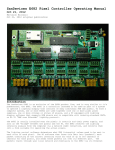
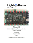
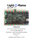
For best results, the cluster(s) being used for DMX should have the Balanced Output jumpers in place so that the output
becomes a standard 2-wire ‘balanced’ DMX signal.
This feature can also be used in conjunction with a balanced receiver (located at the pixel string), to drive 3-wire pixels
over much longer distances than are achievable with the standard unbalanced pixel data signal. This is limited to 3-wire
pixels because the CLOCK signal is not available in this mode.
Please note that this type of output will not have the full drive capability of purpose-built DMX hardware. This feature is
intended primarily to drive limited numbers of DMX fixtures over relatively short distances (say tens to hundreds of feet
rather than thousands). It may also be necessary to substitute pluggable resistor packs of a different value for optimum
performance in balanced mode. The proposed configuration should be tested to insure proper operation prior to
installation.