1
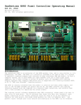
Figure 2: E682 Circuit Board Layout (The highlighted areas in the above illustration indicate user-configurable jumpers or connection points) It is recommend that you read this manual in its entirety, plan your pixel layout once you have familiarized yourself with the capabilities of the E682, and once you have that plan in mind, proceed with the setup of the E682. Setting On-Board Jumpers: Although most of the E682 configuration is done via the web page, there are a few options that are selected with jumpers. There are 2 sets of option jumpers on the E682. In the upper-right hand corner of the board are the Power Select Jumpers, designated as J21. There are 5 terminal pins numbered 1 through 5. There are three possible configurations of these jumpers in this area, depending on the power source for the E682. Typically the E682 will be powered from the pixel power supply attached to J19, since this eliminates the need for a separate power supply. If the E682 is to be powered from the pixel power source (most common case), then set power select jumpers as follows: If the pixel power supply connected to J19 is 5 volts, install a jumper between pins 2 and 3 ONLY For pixel power voltages greater than 5V on J19, install a jumper between pins 1 and 2, and a jumper between pins 3 and 4. If you elect to power the E682 from a separate power supply install a jumper between pins 1 and 2, and a jumper between pins 4 and 5. In this case connect the external supply to J17, the upper terminal is positive, and the 2nd terminal from the top is negative. The external power supply should be from 7 to 24VDC, and capable of supplying at least 500ma, or 1500ma if powering an Ethernet switch from J17. The external supply should be current-limited or fused at no more than 2 amps. The standard configuration that E682s are shipped from the factory is for 12V power (jumpers 1-2 and 3-4).