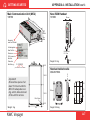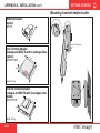
1
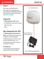
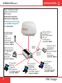
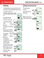
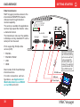
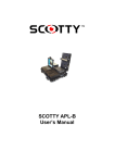
Back to Start Page NWC Voyager Getting Started GETTING STARTED CONTENTS INTRODUCTION .......................................5 General ............................................................. 5 Antenna Unit ...................................................... 5 Main Communication Unit - MCU ...................... 5 Communication services ................................... 6 SIM card (for GAN services) .............................. 9 OPERATION FROM HANDSET .............. 10 Switching ON .................................................... 11 Nera ISDN Handset ..........................................11 NWC Voyager starts up ................................... 12 Making a call ................................................... 12 Redialing ......................................................... 13 Dialing from phone book .................................. 13 Incoming calls to handset ................................ 14 Call hold and transfer ...................................... 14 Internal communication ................................... 15 Various call procedures ................................... 15 To call NWC Voyager ...................................... 16 Phone book entry ............................................ 16 Phone book editing .......................................... 17 HANDSET FUNCTIONS ........................ 18 Overview ......................................................... Satellite search ................................................ Satellite Coverage Map ................................... Phone setup: ................................................... - keyclick ......................................................... NWC Voyager 18 20 21 23 23 Rev Date: February 2004 - ringer ............................................................. 24 - answer beep .................................................. 24 - backlight On/Off ............................................ 25 - protocol ......................................................... 25 - software version ............................................ 26 Selecting default Net service provider ............. 26 Setting serial ports ........................................... 27 Information available ....................................... 28 Alarm ............................................................... 28 TELEFAX SERVICE ................................ 29 General ........................................................... 29 Limitations ....................................................... 29 Installation ....................................................... 29 Transmission ................................................... 29 DATA SERVICE ....................................... 30 Data transmission ............................................ 30 Mobile Packet Data Service ............................. 31 OPERATION FROM PC .......................... 32 Installing the PC program ................................ 32 MAINTENANCE ...................................... 34 General ........................................................... 34 TROUBLESHOOTING ............................ 35 LIST OF TERMS ..................................... 38 Publication No.: 104401 (Rev. 1.0) 3 GETTING STARTED APPENDIX A - INSTALLATION ............. A-1 Location of Antenna Unit ................................ A-2 Coax cable ..................................................... A-2 Optional antenna cable ................................... A-3 Power source ................................................. A-3 Connecting up ................................................ A-4 Mounting the antenna radome ........................ A-5 Outline dimensions ......................................... A-6 Mounting handset holder/cradle ...................... A-8 MCU connectors ............................................. A-9 Connecting up - examples ............................ A-11 ISDN telephones/equipment ......................... A-12 ISDN bus termination ................................... A-13 ISDN cable lengths ....................................... A-13 ISDN wall socket .......................................... A-14 ISDN connectors .......................................... A-14 Cable pinouts ................................................ A-15 Serial printer settings .................................... A-16 NWC Voyager w/GPS (option) ..................... A-17 NMEA-0183 input sources (complies with IEC 61162-1) ......................... A-18 Mounting connector type 11N-50-3-54 (for cable RG223) ......................................... A-19 Mounting connector type 11N-50-7-5 (for cables RG214 FRNC) ............................ A-20 APPENDIX B CONNECTING UP NERA TA ................ B-1 APPENDIX B CONNECTING UP BCS iTA .................. B-3 APPENDIX C TERMINAL IDENTITIES ....................... C-1 All specifications are subject to change without notice. © Nera SatCom AS, 2004 A MEMBER OF CIRM The NWC Voyager terminal fully complies with the R&TTE directive. 4 NWC Voyager GETTING STARTED INTRODUCTION General NWC Voyager is a GAN satellite terminal. NWC Voyager offers 4.8 kbps/64 kbps speech, telefax, data service and MPDS (Mobile Packet Data Service) within the Inmarsat spot beam coverage, see Satellite Coverage Map. Roof mounted Antenna Unit Antenna Unit The NWC Voyager Antenna Unit consists of: • Servo stabilized antenna dish with RF-Transceiver • GPS receiver (option) • Radome Main Communication Unit - MCU The NWC Voyager Main Communication Unit (MCU) - which constitutes the major electronic part is designed for wall or desktop installation. The MCU power input is 10.8 - 32 VDC. The maximum power requirement is approx. 110 W. The MCU supplies 48 VDC power to the Antenna Unit through the coaxial cable. Nera ISDN Handset The handset keypad and built-in display allows dialing and control of the MCU and antenna. NWC Voyager Main Communication Unit with Nera ISDN Handset Figure 1 NWC Voyager satellite terminal. 5 INTRODUCTION CONT’D GETTING STARTED Communication services Spot beam services • Speech: - 64 kbps / 4.8 kbps • Data: - 56/64 kbps (UDI) • MPDS - Mobile Packet Data Service FWD = 64 kbps, RTN = 64 kbps Shared channel • Telefax: - 64 kbps Group 4 Group 3 via Terminal Adapter (TA) • Audio: - 3.1 kHz (Audio) Internal communication Equipment connected to the various interfaces may communicate with each other via an internal MSN (Mobile Subscriber Number) assigned to each unit. Control interface The RS-232/RS-422 or USB port allows connection of a PC for configuration of the NWC Voyager MCU. A PC program (vtLite Mobile) that provides the software to operate and configure the MCU is supplied on the enclosed CD (requires at least Windows 98). CD The CD ROM supplied with NWC Voyager contains: • program for control from PC (vtLite Mobile) • manuals • application notes • modem drivers • and other useful information. Additional equipment • Additional Nera ISDN Handsets • PC • Videophone • Group 4 telefax • Terminal Adapter for connection of: - analogue DTMF telephone(s) - Group 3 telefax • Printer w/RS-232 serial card Figure 2 Additional equipment. ISDN Telenor IOR Ready for call OK DEL 1 2 4 ghi 7 pqrs abc 3 def 5 jkl 6 mno 8 tuv 9 wyz 0 TEL1 POW ER TEL2 Additional Nera ISDN Handsets 6 PC Terminal Adapter Analogue telephones (wall or desk) Telefax (Group 4) Telefax (Group 3) Serial printer NWC Voyager GETTING STARTED INTRODUCTION CONT’D Radome (cutaway view) Antenna Dish RF-Transceiver Servo Stabilized Pedestal Figure 3 NWC Voyager - Antenna Unit parts. NWC Voyager 7 GETTING STARTED INTRODUCTION CONT’D Figure 4 Examples of preprogrammed Terminal Ids and MSN numbers. Allows direct connection without prior configuration. See also Routing of incoming calls and MSN configuration in the User Guide. Nera ISDN Handset connected to ISDN port/bus: 4.8 kbps speech 64 kbps speech Term Id 01, MSN 20 Term Id 91, MSN 30 DIAL 00+INTL TEL.NO.+ ON FUNC SHIFT ALPHA MORE/ HELP SHIFT BAT ALPHA ENTER LES PTT ON/OFF LIST ESC 1 DEL 2 DEF 4 JKL 5 MNO 7 STU 8 VWX 0 ÄÖÜ ABC DATA ØÅ. PLAY TAX LIST 3 GHI 6 PQR 9 YZÆ LIGHT SPC Digital fax (G4), video conference equipment, PC or ISDN router connected to ISDN port/bus: 64 kbps data Term Id 51, MSN 60 PC connected to RS232A port: 64 kbps data MPDS supported vt-Lite Mobile supported Term Id 52, MSN 61 8 Analogue telephone connected via Nera Terminal Adapter TEL1 port: 4.8 kbps speech Term Id 02, MSN 21 Terminal Adapter TEL1 POWE R ON DC OUT SYNC ALARM 2 RS-23 1 4 3 2 A 2B RS-23 1 4 3 2 5 ISDN 1 8 8 1 USB TEL2 For programming of TA, see Appendix B ISDN 5 6 9 8 7 6 9 8 7 PC connected to RS232B port: 64 kbps data MPDS supported vtLite Mobile supported Term Id 53, MSN 62 Analogue fax (G3) or crypto telephone connected via Nera Terminal Adapter TEL2 port: 3.1 kHz Audio Term Id 61, MSN 40 PC connected to USB port: 64 kbps data MPDS supported vtLite Mobile supported Term Id 54, MSN 63 NWC Voyager GETTING STARTED SIM card (for GAN services) The SIM card carries subscription information from your Net service provider on an integrated circuit. The NWC Voyager used with the SIM card assumes the identity of the SIM card. The SIM card has its own set of Inmarsat Mobile Numbers (IMN) on which the user can be contacted irrespective of the NWC Voyager used. All outgoing calls will be billed to the owner of the SIM card. The SIM card is protected by a SIM PIN (Personal Identification Number). Contact your Net service provider if you do not have the PIN code. If the PIN code entered does not match the PIN code on the SIM card, operation with that particular SIM card will lock-up after three failed attempts. You must then use the SIM un-block code (PUK code) provided by your Net service provider to un-lock the card. Contact your Net service provider if you do not have the PUK code. Note! When the PUK is used, the SIM PIN is set to 1 2 3 4. To change or disable the PIN code, see User Guide > Access level on the enclosed CD. The SIM card can store various information, e.g.: • PIN code (Personal Identification Number) • Phone book • Allowed Net service providers NWC Voyager INTRODUCTION CONT’D Note! NWC Voyager can be used with or without SIM card. The Net service provider, however, sometimes requires the use of SIM card. The SIM card is located on the rear panel of the Main Communication Unit, see figure 6. The cover must be removed to access the the card slot. The cover is attached by two serrated screws. No tools are required to loosen the screws. PIN code The user is prompted for the 4-8 digit Personal Identification Number each time the NWC Voyager is switched on: • SIM PIN? NWC Voyager SIM PIN: _ • PIN? NWC Voyager PIN: _ (with SIM card) (without SIM card) The PIN protection can be disabled, see "Access level" in the User Guide. 9 GETTING STARTED OPERATION FROM HANDSET Handsfree microphone Display indicators: appears at hook OFF flashes when receiving a call Net provider&Ocean Region appears when loudspeaker is ON ALPHA appears when selecting letters on the keypad, e.g. for Phone Book entries signal strength indicator alarm indicator ISDN ALPHA Telenor IOR Ready for call Hook ON magnet click! Function keys: allows adjusting the earpiece volume during conversation opens/closes Phone Book reverts to previous postion used to transfer a call selects function menu handsfree microphone/ loudspeaker ON/OFF (hook ON/OFF when in cradle) hook ON/OFF . . . . . number keys. The keys include letters for Phone Book entries. enters selected choice LIST deletes last character or complete entry scrolls up/down through function menu/choices Handsfree loudspeaker Figure 5 Display and keys. 10 Figure 6 Holder/cradle wallmounted. NWC Voyager GETTING STARTED OPERATION FROM HANDSET CONT’D Switching ON The ON/OFF switch located on the rear panel of the Main Communication Unit switches all basic units of the NWC Voyager terminal on/off: • the Nera ISDN Handset • the Main Communication Unit (MCU), and • the Antenna Unit. See figure 6 for location of the power ON/OFF switch and indicator. SIM card Cover ON/OFF 11-32 VDC / 110W NOT IN USE RF SIM CARD (50 TERM) Nera ISDN Handset SIM CARD INSIDE When connected initially, the Handset is set to Mobile mode, see next page. WHEN CHANGING MODEM UNIT REMOVE COVER AND TAKE OUT SIM CARD Power ON/OFF switch Power indicator If the Handset display reads: (Normal mode) Open the MENU: 09:15 April 03 4.8 Speech MENU and scroll down to M ai n ON T DC OU SYNC Co m m un i ca tio ALARM n 2A RS4-23 3 2 1 B RS-232 2 1 5 4 3 5 ISDN USB 1 8 8 1 ISDN 6 9 8 7 Un 6 9 8 7 it - M CU For remote controlled Power ON/OFF, see Appendix A-Installation Figure 6 Location of SIM card and ON/OFF switch. NWC Voyager Set to Fleet (Mobile mode): Pressing OK provides an idle display as shown on the next page. OK > Active MSN Keyclick Ringer Answer beep Backlight Language MSN Protocol SW version Set to Fleet To toggle between Normal and Mobile mode, unplug Handset and press and hold down DEL when reconnecting it. For Normal mode, see Nera ISDN Handset - User Guide on CD. 11 GETTING STARTED OPERATION FROM HANDSET CONT’D NWC Voyager starts up Making a call NWC Voyager automatically initializes the system and searches for the satellite (handset in Mobile Mode): • Dial 00, country code and subscriber number, e.g.: 0 0 4 abc 7pqrs 6mno 7pqrs 2 abc 4 abc 4 abc 7pqrs 0 # Initializing . . . 1...100% A a Searching IOR Telenor IOR Beam Search See Satellite search later in this manual to restart a search manually. Telenor IOR Ready for call Use DEL to modify entries: DEL Pressing DEL once, erases one digit. Holding the key more than 0.5 second erases the whole number. • When entered, the display reads: • When the remote end answers, the display reads: Idle When idle, the Nera ISDN Handset displays: Telenor IOR Ready for call Alarm indicator See Information available > Alarms&Messages The timer starts. • End the call by pressing Calling... 004767244700 Connected 09:46 004767244700- Dash separates additional dialing Timer, minutes:seconds Disconnected hook ON/OFF , or replacing the handset in the cradle. Use the handsfree key ON/OFF. to toggle the loudspeaker Alternative dialing: or for dialing tone, then dial the number: Press 0 12 Dial (4.8) 004767244700 For normal call For handsfree call Sends dialed number Mobile Euro-ISDN Ocean Region Service provider Status Signal strength indicator 0 0 4 abc 7pqrs 6mno 7pqrs 2 abc 4 abc 4 abc 7pqrs 0 0 # A a NWC Voyager GETTING STARTED OPERATION FROM HANDSET CONT’D Redialing The Redial Memory stores the last 30 called and received numbers (incoming IMN numbers are not conveyed from "ashore"). The data are erased when disconnecting the handset or NWC Voyager is switched off. Telenor IOR Ready for call To redial calls made: to recall the last number dialed: Redial list if no number is stored 2 Use the arrow keys to scroll through the list: 3 Pressing hook ON/OFF sends the chosen number: ALPHA »BT Nera SatCom LIST 2 Press the hook key to ALPHA BT OUT:JAN17 15:09 004767244700 01 OUT:JAN25 12:10 004722763110 02 Received call To view calls list if no number is stored received: Internal call 4 Press the arrow down key to recall the last External call number received. Scroll through list. NWC Voyager book key: and scroll through the phone book: call the selected number: 1 Press the arrow up key To delete a listed number: 5 Press DEL to clear the chosen number from list: Press OK to delete: Revert to idle: Dialing from phone book 1 Press the phone Calling... IN:JAN20 13:09 20 01 IN:FEB10 16:11 unknown no. 02 DEL OK Clear? 20 OK 13 GETTING STARTED OPERATION FROM HANDSET CONT’D Incoming calls to handset Call hold and transfer The handset rings when receiving a call. The ringing symbol flashes until the call is answered. Pressing R during a conversation will put the current call on hold. Another internal call may now be made. 4.8 Speech • Answer the call by pressing hook ON/OFF: handsfree: or • End the call by pressing hook ON/OFF replacing the handset in the cradle. • Reject the call by pressing DEL: 14 R , [MSN] With the Nera ISDN Handset in 00:00 the cradle, the loudspeaker and microphone are ON for handsfree operation. Timer, If lifting the handset, the loudminutes:seconds speaker turns OFF. Use the handsfree key to toggle the loudspeaker ON/OFF. Note! If the ringing symbol idle, you have missed a call. Switching between the two calls: • After putting the 1st call on hold by pressing the 2nd call is established by keying: • The 1st call is put on hold, and the 2nd is connected. • Toggling between the two calls is achieved by pressing R repeatedly: 1 on hold **20# R 2 on hold , or Call transfer (connection via satellite): DEL is displayed when in MSN/Handset Id R 2 0 Hang up R toggles between subscribers Exception! Transfer from analogue to ISDN is not possible. NWC Voyager GETTING STARTED OPERATION FROM HANDSET CONT’D Internal communication Various call procedures NWC Voyager allows calls to be made internally between the connected ISDN and analogue telephones. Call from a standard telephone Internal calls: MSN (example) 2 0 When receiving a call to an ISDN phone, the caller`s MSN number will appear in the display (if programmed). When NWC Voyager is busy with a satellite link data call, it is possible to make internal calls. Example of internal call connections: MCU ISDN ISDN Telenor IOR Ready for call Telenor IOR Ready for call OK ISDN 2 4 ghi 7 pqrs abc DEL 3 def 5 jkl 6 mno 8 tuv 9 wyz 0 1 2 4 ghi 7 pqrs abc 3 def 5 jkl 6 mno 8 tuv 9 wyz 0 TA Analogue phone MSN21 Nera ISDN Handset MSN22 MSN31 7 6 7 2 4 4 7 0 ISDN DECT phone MSN23 0 Short number dialing (prefix 23) through selected Net service provider 4 2 3 1 5 fetches and sends the telephone number stored under short number 15 via the selected Net service provider (Telenor=no. 4). Service calls Special information services are accessible with 2-digit service address code. Note! Not all Net service providers offer every service. Example: Calling the technical staff of the Land Earth Station (LES): 3 3 0 4 7 6 7 2 4 4 6 2 as the last digit 1 START Note! Some types of equipment do not have # implemented in software even if the #-key is on the keypad. Then in front of the telephone number use: 903 if dialing the number digit by digit, or 902 if for the number to be sent as a block. e.g.: 9 NWC Voyager 4 Short number dialing from Phone Book (prefix 23) 2 3 1 5 fetches and sends the telephone number stored in the Phone Book under short number 15. 0 Nera ISDN Handset MSN20 MSN30 0 Telefax On a telefax with keypad, enter before starting transmission: OK DEL 1 POWER 0 0 2 0 0 4 7 6 7 2 4 4 7 0 0 15 GETTING STARTED OPERATION FROM HANDSET CONT’D To call NWC Voyager Phone book entry Dial the international prefix (normally 00) followed by 870 and the IMN number, e.g. 00 870 762420510. The common Ocean Region access no. 870 connects the call to the dialed NWC Voyager terminal regardless of the Ocean Region the terminal user currently communicates through. The entries in the NWC Voyager phone book may consist of maximum 100 numbers. The number/ name list is stored in the Main Communication Unit. If the PSTN network does not support access no. 870, call the Ocean Region directly: 871 – AOR-E (Atlantic Ocean Region East) 872 – POR (Pacific Ocean Region) 873 – IOR (Indian Ocean Region) 874 – AOR-W (Atlantic Ocean Region West) Programming: 1 Open the phone book > menu: Open the Add entry function by pressing Ok before starting to key in characters. 2 Enter the name, e.g. Nera ASA. ALPHA OK # A a 6mno Add name: N_ 3 def Add name: Ne_ 7pqrs Add name: Ner_ 2 abc Add name: Nera_ 0 Add name: Nera _ 2 abc Add name: Nera_A 7pqrs Add name: Nera_AS 2 abc Add name: Nera_ASA ALPHA ALPHA Note that the additional characters accessible with the key appear momentarily. See the character table on next page. For modifying an entry, see Phone book editing on next page. Enter the phone number, continue on next page . . . . 16 »Add entry Edit number ALPHA ALPHA ALPHA # A a ALPHA ALPHA NWC Voyager GETTING STARTED OPERATION FROM HANDSET CONT’D 3 Enter the telephone number e.g.: 0 0 Phone book editing 4 abc 7pqrs Number: 004767244700 Open phone book menu and scroll down to the required function. Saving If "Sort by ShrtNo" is selected, the function switches to "Sort by Name". ALPHA 6mno 7pqrs 2 abc 4 abc 4 abc 7pqrs 0 4 Pressing stores the entry in the phone book: 0 OK OK An entry can be erased by pressing DEL »Nera ASA Neratek Revert to idle: Telenor IOR Ready for call ALPHA appears when letters are to be entered. »Add Entry Edit number Edit name Delete Search book See number Copy Sort by ShrtNo ALPHA Add Entry OK Add name: Nera SatCom_ Edit number OK Number: 004767244700 Edit name OK Edit name: Nera SatCom Del OK Deleting Search book OK Name search: _ See number OK [1] 0047672447 00 Copy OK Short Number: 2_ Sort by ShrtNo OK [1] 0047672447 00 Sort by name OK Nera SatCom ALPHA The character table shows all the characters accessible: Notes: • The # -key toggles between upper-case and lower-case characters. • Names written with none Anglo-American characters such as Æ, Ø, Å etc., can only contain 6 different special characters (however, 2 equal characters count as 1). NWC Voyager Key Uppercase Lowercase 1 .,?!-:;/1 .,?!-:;/1 2 abc ABCÆÅÄ2 abcæåä2 3 def DEF3 def3 4 abc GHI4 ghi4 5 jkl JKL5 jkl5 6mno MNOØÖ6 mnoøö6 7pqrs PQRS7 pqrs7 8 tuv TUVÜ8 tuvü8 9wxyz WXYZ9 wxyz9 0 _0 _0 Use DEL to modify entries. ALPHA ALPHA ALPHA ALPHA ALPHA 17 GETTING STARTED HANDSET FUNCTIONS Overview »Sat. Search Phone setup Set Network Ports Information Opening Search »Search last 2 Search all AOR-W AOR-E POR IOR Region 4 Region 5 Region 6 Region 7 Not in use MENU »Active MSN Keyclick Ringer Answer beep Backlight Protocol SW version 18 reverts to idle Tuning to IOR Elevation 17 Telenor IOR Ready for call Elevation: 0...90º »#1: 4.8 Speech #2: 64 Speech »On Off »Tone Volume 1.3.00 270103 »On Off »Euro-ISDN NI-1 »On Off 30 second Dimmer »002/Stratos 004/Telenor 005/OTE 012/XANTIC ESC Searching... IOR Elevation 0 »Tone#1 Tone#2 Tone#3 Tone#4 Tone#5 Tone#6 Tone#7 Tone#8 Tone#9 »Low Medium High Increasing Dimmer [100%] 90% 10% See next page NWC Voyager GETTING STARTED HANDSET FUNCTIONS CONT’D Overview cont'd MENU »Sat. Search Phone setup Set Network Serial Ports Information »Speed Format Flow control »Port A Port B COM defaults NMEA port »On Off »Driver switch Speed Format Flow control »RS-232 RS-422 »Dump trf. log »Enable Disable »Diagnostics Traffic log Forward Id Version Info Network Info Alarms & Msgs Position Speed/course »HW (fwd):A98853 IOR Spot: 5 Ready for call NCSC Curr: 1 NCSC Actv: 0 Registration SUCCESSFUL Course over ground Note! Not to be used for navigation »Clear Causes Alarms List Info Log ESC 103920 Ver: 1.0 30 December 200 1.0 2.00 1.30 d=7,p=none,s=1 d=7,p=e,s=1 d=7,p=0,s=1 d=7,p=m,s=1 d=7,p=s,s=2 » d=8,p=none,s=1 d=8,p=e,s=1 d=8,p=0,s=1 d=8,p=m,s=1 d=8,p=s,s=1 d=8,p=none,s=2 d=8,p=e,s=2 d=8,p=0,s=2 d=8,p=m,s=2 none »rts/cts <E>xon/xoff tr <E>xon/xoff st »default settings 1.00 Logging mode needs to be set to print to RS232 in vtLite Traffic Log Option »System Ctrl SW DSP Monitor KDB RFB ATB Only appears with Diagnostics On »Speed: 0.0 Course: 000 Speed in knots NWC 103920 1.0 18 Feb 2004 1200bps 2400bps 4800bps 9600bps 19200bps 38400bps 57600bps »115200bps »010d29m02s E 059d52m11s N Voyager 301.00 reverts to idle NWC Voyager 19 GETTING STARTED HANDSET FUNCTIONS CONT’D Satellite search To select another Ocean Region: Some geographic locations allow contact with more than one Ocean Region satellite. It is recommended to choose an Ocean Region providing good signal quality and cost-effective communication. Use the Satellite Coverage Map on next pages to select the Ocean Region at your location: 1 Open the MENU and Atlantic Ocean Region West: Atlantic Ocean Region East: Pacific Ocean Region: Indian Ocean Region: Regions 4 - 7 are not in use. 20 AOR-W AOR-E POR IOR »Sat. Search Phone setup Set Network Ports Information press Sat. Search: Pressing OK opens the list of searching alternatives: 2 Select as required: OK Opening Search OK »Search last 2 Search all AOR-W AOR-E POR IOR When selecting Search last 2, the antenna starts searching for the last used satellite/ elevation (Ocean Region) as default. If not found the system searches for the 2nd last used. When selecting Search all the antenna searches one Ocean Region after the other. When selecting a specific Ocean Region (AOR-W, AOR-E, POR or IOR) the system knows the elevation and will find the satellite fast if visible. The antenna performs an hemispheric search at antenna elevation angles varying within 0º through 90º. Searching... IOR Elevation 0 Tuning to IOR Elevation 17 Telenor IOR Logging On Telenor IOR Ready for call NWC Voyager GETTING STARTED HANDSET FUNCTIONS CONT’D Satellite Coverage Map NWC Voyager coverage POR Coverage with low rate voice and data services AOR-W AOR-E IOR POR S Equator N NWC Voyager NE 21 HANDSET FUNCTIONS CONT’D GETTING STARTED Coverage map for each Ocean Region IOR AOR-W AOR-E 22 POR NWC Voyager GETTING STARTED Phone setup (Nera ISDN Handset) Active MSN (Multiple Subscriber Number) When making a call, the device connected to NWC Voyager identifies itself locally by its MSN number. The first Nera ISDN Handset connected has the following MSN numbers: Terminal Id MSN number Speech quality 01 20 4.8 Speech 91 30 64 K Speech HANDSET FUNCTIONS CONT’D Keyclick When activated, a click is heard when pressing a key. The keyclick can be turned on/off as follows: 1 Open the MENU and scroll down to Phone setup: 2 Select the Keyclick function: 3 Press OK and scroll to On or Off, as required: 4 Press setting. NWC Voyager OK Sat. Search »Phone setup Set Network Ports Information OK Active MSN »Keyclick OK »On Off to store the 23 GETTING STARTED HANDSET FUNCTIONS CONT’D Ringer The tone sound and level heard when the phone rings may be selected as follows: 1 Open the MENU and select Phone setup > Ringer: 2 Press to select the Tone function: OK Sat. Search »Phone setup Set Network Ports Information OK OK 3 Press OK again and scroll down to required tone: OK Press OK to store the selected one. 4 Select the Ringer function again and scroll down to the Volume function: Keyclick »Ringer 24 The answer beep can be turned on/off as follows: 1 Open the MENU: »Tone Volume »Tone#1 Tone#2 Tone#3 Tone#4 Tone#5 Tone#6 Tone#7 Tone#8 Tone#9 Sat. Search »Phone setup Set Network Ports Information scroll down to Phone setup, and select the Active MSN function: OK 2 Scroll down to the An- »Active MSN Keyclick Ringer »Answer beep swer beep function: 3 Press OK Tone » Volume OK »Low Medium High Increasing 5 Pressing OK lists the choices: Scroll down to required sound level, and press OK to store it: Answer beep NWC Voyager may be set to emit a signal in the handset when an outgoing call is answered. The signal will also sound when a call is transferred at the remote end. The signal is not active during handsfree calls. OK and scroll to On or Off, as required: OK »On Off 4 Pressing OK stores the chosen mode. NWC Voyager GETTING STARTED HANDSET FUNCTIONS CONT’D Backlight On/Off The display and keypad backlight can be set to: • On, permanently ON • Off, permanently OFF • 30 seconds ON when pressing a key or receiving a call, and stays ON 30 secs after last event. • Dimmer, intensity adjustable in 10 steps. Changing the setting: 1 Open the MENU: scroll down to Phone setup, Sat. Search »Phone setup Set Network Ports Information The check for current protocol: 1 Open the MENU: Sat. Search »Phone setup Set Network Ports Information scroll down to Phone setup, and OK 3 Press OK and scroll down to required setting: 4 Pressing at Dimmer opens the backlight adjustment window: »Active MSN Keyclick Answer beep »Backlight scroll down to the Backlight function: OK »On Off 30 second Dimmer OK OK Dimmer [100%] 90% Adjust with up/down arrows: 5 Press Protocol NWC Voyager allows selection between the following ISDN protocols: • Euro ISDN for connection to equipment conforming to the European ISDN standard (default) • NI-1 protocol for equipment conforming to the NI-1 standard (National ISDN-1). • All ISDN devices and MCU must use the same protocol. OK to store. NWC Voyager LIST 10% and OK »Active MSN Keyclick Backlight »Protocol select the Protocol function: 2 Press OK and scroll required protocol: 3 Pressing OK stores the chosen ISDN protocol. OK »Euro-ISDN NI-1 To change the default setting in the MCU, see User Guide > ISDN protocol configuration on the CD. 25 GETTING STARTED HANDSET FUNCTIONS CONT’D Software version This function displays the Nera ISDN Handset software version: 1 Open the MENU: Sat. Search »Phone setup Set Network Ports Information scroll down to Phone setup, and OK select the SW version function: 3 Press »Active MSN Keyclick Protocol »SW version Selecting default Net service provider The default Net service provider for a satellite (Ocean Region) is automatically used when dialing ship-to-shore. When using SIM card, selection of a default Net service provider is restricted to the one stored on the SIM card! Changing default Net service provider: 1 Open the MENU: Sat. Search Phone setup »Set Network Ports Information Scroll down to Set Network: 2 Scroll down to the required OK to read: OK 1.3.00 270103 To read other software versions, see Information available later in the manual. Net service provider: OK »001/Telenor 002/Stratos 004/Telenor 005/OTE 007/Indosat 011/France Tel 012/Xantic 022/Xantic 060/Malaysia T 210/Singapore 555/Telecom It OK Saving data .... 3 Store the new Net service provider for the current Ocean Region: To preprogramme Net provider for all Ocean Regions, vt-Lite Mobile must be used, see User Guide on CD. 26 NWC Voyager GETTING STARTED HANDSET FUNCTIONS CONT’D Setting serial ports The data speed, format and flow control for the RS-232 serial ports A and B are set up as follows: 1 Open the MENU Sat. Search Phone setup Set Network »Ports Information and scroll down to Ports: See Overview for available choices. OK 2 Select the parameter »Port A Port B COM defaults NMEA port to be set for Port A: OK 3 Select listed data: Speed 115200bps (default): Format 8 data bits, no parity and 1 stop bit (default) Flow control rts/cts (default): »Speed Format Flow control Set Network »Ports Information 6 Select Ports: and OK »115200bps » d=8,p=none,s=1 d=8,p=e,s=1 Port A »Port B scroll down to Port B: 7 Open the Driver OK switch function: OK and OK »Driver Switch Speed Format Flow control RS-232 »RS-422 scroll down to RS-422: none »rts/cts 4 Disable/enable NMEA port as required: Port B driver switch Select data speed, format and flow control as described for serial port A. Switching the driver from Sat. Search Phone setup RS-232B to RS-422: OK »Enable Disable The RS-422 terminal block is now activated for connection of e.g. PC using cables of up to 100 m. The RS-232 serial port B is disconnected. NWC Voyager 27 GETTING STARTED HANDSET FUNCTIONS CONT’D Information available »Sat. Search Phone setup Set Network Priority Call Ports Information Open the menu and scroll down to read various information, as indicated (examples): Alarm The alarm indicator flashes when an alarm condition occurs: OK »Diagnostics Traffic log Forward Id Version Info Network Info Alarms & Msgs Position Speed/course OK On Off Telenor IOR Ready for call Alarm indicator The indicator stops once the alarm has been read in the Display Handset by pressing > Information > Alarms & messages. The indicator continues to be displayed if the alarm condition persists. The red alarm indicator on the MCU (see next page) flashes in step with the alarm indicator in the display. »Dump trf. log IOR Spot: 5 Ready for call OK Rel 1.0 15 Apr 2003 Speed in knots Course over ground Note! Not to be used for navigation 1.0 1.05 »Clear Causes Alarms List Info Log 010d29m02s E 059d52m11s N Speed: 0.0 Course: 000 28 »System Ctrl SW DSP Monitor KDB RFB ATB 101476 Ver: 1.0 10 Apr 2003 Only appears with Diagnostics ON HW (fwd):A98853 OK OK OK OK 1)IFII/03501 Subscriber busy 1)Burst not sent 1)No contact with GPS 1.30 1.100 Voyager 0.20 NWC Voyager GETTING STARTED TELEFAX SERVICE General NWC Voyager provides access to telefax service: • Group 4 fax at 64 kbps via the ISDN connector. • Group 3 fax via the Terminal Adapter. • Group 3 fax using 3.1 kHz Audio service. If a call failure should occur while sending a multipage document, re-send only the failed pages. G4: one page normally takes 10 seconds (G4 fax is required in both ends of the line). Limitations NWC Voyager is fully compatible with the world’s leading telefax machines and telefax software standards. However, transmission may not be possible through some of the telefax machines available on the market. Please check with your Net service provider/Nera Distributor before purchasing a telefax for use with NWC Voyager. Installation For installation of Terminal Adapter, see Appendix B. ON DC OUT SYNC ALARM RS-232 A RS-232 B 9 8 7 6 9 8 7 6 5 4 3 2 1 1 8 5 4 3 2 1 8 1 MCU Transmission To send a fax, use the same dialing sequence as when making a call. See Various call procedures earlier in this manual. Terminal Adapter TEL 1 POW ER TEL Note! On a telefax with keypad, enter last digit before starting transmission. G3: telefax transmissions normally take 1 minute per standard text page using standard resolution. Using superfine or halftone resolution will double the transmission time. To save time, avoid using a separate cover page. NWC Voyager 2 as the Digital telefax (G4) Analogue telephone Analogue telefax (G3) 29 GETTING STARTED DATA SERVICE Data transmission NWC Voyager provides access to the international ISDN/PSTN network data services through its built-in modem capability. The service is suitable for applications such as high-speed file transfer, video, e-mail and internet. The transmisson rate over the satellite is 64 kbps, and any standard PC with a serial port can be used. ON DC OUT SYNC ALARM RS-232 A RS-232 B 9 8 7 6 9 8 7 6 5 4 3 2 1 1 8 5 4 3 2 1 8 1 Ports supporting 64 kbps data service (UDI): RS232A RS232B / RS422 USB ISDN Dial number 28 for fixed 64 kbps internet services. For other connections and configurations, see Applications > Mobile Data Service via RS232 or via USB on the CD. The driver used with the RS-232 B (DATA) port can be switched to be used with the RS-422 (DATA) port instead. The switching is performed with the Nera ISDN Handset. Ma me x 100 tre s • • • • PC ISDN card USB port PC serial port DTE 30 NWC Voyager GETTING STARTED Mobile Packet Data Service The MPDS service can be efficient for applications such as: • E-mail • Internet/intranet • Navigational updates • Vessel telemetry transmission • Database queries • E-commerce NWC Voyager The user only pays for the amount of data sent over the network, and not for the time connected. Ports supporting MPDS: • RS232A • RS232B / RS422 • USB No configuration is needed! Dial number **94# to set up an MPDS call. See Applications > MPDS via RS232 or via USB on the NWC Voyager CD. 31 GETTING STARTED OPERATION FROM PC Installing the PC program The vtLite Mobile program allows NWC Voyager to be operated or configured from a PC, including functions such as: • Phone book • Traffic log • Configuration of ports (ISDN/USB/RS-232/RS422) • Configuration of the MCU Connect the PC as indicated on the previous page. The vtLite Mobile program is available on the enclosed CD and must be installed on the PC hard disk. For an explanation of the functions, see the User Guide on the CD. Close any Acrobat Reader program open on the PC before proceeding. See next page. Nera vtLite PC program 32 NWC Voyager GETTING STARTED Procedure: 1 Insert the CD : The Start Page opens automatically in a few seconds. OPERATION FROM PC CONT’D 6 Click Configure > Port to check the port settings. (Alternatively, open the Acrobat file “NWC Voyager_StartPage” on the CD. If necessary, install Acrobat Reader by clicking “Ar505enu.exe” in the “SW Installation” folder.) 2 Click “Software Installation” and then “vtLite Mobile”. Allow files to load on to the PC hard disk. The installation of the program starts automatically when files have been loaded. 3 Connect the serial cable between the PC serial port and one of the RS-232 ports on the NWC Voyager Main Communication Unit. See DATA SERVICE. 4 Switch ON the Main Communication Unit. 5 Start the vtLite Mobile program by clicking Start>Programs>vtLite Mobile. If no contact, click Mode>Terminal MMI. NWC Voyager 7 The USB port can be used to run vtLite Mobile. The USB modem driver required is accessible on the CD: Nera Generic USB Modem (usb4nera.inf) 33 MAINTENANCE GETTING STARTED General No regular maintenance is required of the NWC Voyager satellite terminal. It is recommended, however, to clean the antenna radome every once in a while. 34 NWC Voyager GETTING STARTED Problem TROUBLESHOOTING Probable cause Action 1. The NWC Voyager MCU power ON indicator does not light up: The Main Communication Unit is not switched ON Set the ON/OFF switch to ON (rear panel). Switch OFF, wait 10 secs and switch back ON Check that the power cord is properly connected to 10.8 - 32 VDC power source. Set the external ON/OFF switch to ON, or verify power switch jumper on front panel connector. Diode info: ON=DC-in OK (>10.8VDC), 48VDC=Internal DC Power output 48V OK 2. The Nera ISDN Handset display freezes or stays completely blank: The handset cord is not connected or damaged Check that the handset cord is properly connected and inspect the cord. Power MCU off/on Disconnect cord from MCU and connect it again. 3. NWC Voyager cannot find the satellite: No or weak signals. Sight to satellite obstructed Obstructions Check that no obstacles block the free sight to the satellite. 4. Low signal reception: 5. NWC Voyager functions abnormally: NWC Voyager Power is not connected The signal strength indicator should preferably exceed 570 in vtLite Mobile, or 5 bars in the Handset display. Check that no obstacles block the free sight to the satellite. Restart the search for any satellite, or try a satellite in a specific Ocean Region. Turn off power and disconnect power, and switch on again. Verify correct voltages to the MCU: 10.8 - 32VDC. Download new software from the Nera website. (preferably done by a Nera Regional Service Centre) 35 GETTING STARTED TROUBLESHOOTING CONT’D Problem 6. Unsuccessful call: Probable cause NWC Voyager is not commissioned. The following messages appear in the vtLite display: No response from net. (HS: Disconnected) 7. Problems with telefax: 36 The called party is busy. Subscriber busy appears in HS display Incomplete dialing Action Check clear cause Call the Net Service Provider. Check that the correct Net service provider is shown in the display. The NWC Voyager terminal is not commissioned. Verify in Nera ISDN Handset menu >Information>Networkinfo>(scrolldown) successful=commissioned, failed=not commissioned. Wait for some time and try again. Call another subscriber. Remember to press "#" as last digit before starting transmission. Instead of "#", try to enter: 902 + 00 + country code + subscriber number. Fax fails to work in Global Beam (0) Works in spot beam only. Service not commissioned See problem 5. System transmission delays The OFF-HOOK time for handshake should be as long as possible (e.g. 2 minutes). When the fax machine is called, ringing time should be set to minimum (e.g. immediate answer). Set error correction to OFF Try a different fax machine. Check that the telefax (Group 3) is properly connected to the Nera Terminal Adapter. Contact the Distributor NWC Voyager GETTING STARTED Problem TROUBLESHOOTING CONT’D Probable cause Action 8. No GPS: option GPS alarm, or GPS not received Wait up to 15 minutes. The GPS may use up 15 minutes if NWC Voyager has switched off for more than 6 hours. 9. Problems with data communication: Wrong PC settings Check the PC program settings: speed 115200bps, 8 data bits, 1 stop bit, no parity if RS232 is used (default settings in NWC Voyager MCU). Shore/land has not ISDN line or does not support UDI service. Read Nera Application guide on VoyagerCD. Contact the PC applications vendor for help. Data Service fails in Global Beam (0) Works in spot beam only. 10.Routing of calls: MSN number not entered properly Make sure that the MSN number entered into Voyager with the Device Manager, is also entered into connected equipment. Some devices, e.g. Nera ISDN Handset, can be programmed with multiple MSNs. Call Handset to verify MSN of other phones. Read Handset MSN by pressing "R"-button. 11.Problem with local calls: Wrong dialing Check that you call the correct MSN number. If Access Code is used, you need to enter this code first. MSN 12.Problem with call transfer NWC Voyager Phone does not support R-button. Not possible to transfer call from analogue to ISDN. 37 LIST OF TERMS AC Alternating Current AOR-E Atlantic Ocean Region East. AOR-W Atlantic Ocean Region West. Azimuth horizontal direction angle between north and, e.g. the direction to the satellite. Bit rate the number of bits transmitted per second (bps). Byte = 8 bits CHV2 higher access level on the SIM card, corresponding to NWC Voyager "owner" level. DC Direct Current. DID Destination terminal IDentification. DSP Digital Signal Processor. DTE Data Terminal Equipment. Elevation vertical angle to the satellite, i.e. the height of the satellite above the horizon. Fleet Inmarsat's single integrated voice, fax, Mobile Data Service and Mobile Packet Data Service. FWD ID forward Id, telephone network identity. GAN Inmarsat Global Area Network. Home LES Home Land Earth Station gives access to MPDS service like Internet / e-mail and handles MPDS billing system. IDU Indoor Unit IMN Inmarsat Mobile Number, a unique 9-digit number which identifies each device connected to NWC Voyager. Inmarsat International Maritime Satellite Organisation. IOR Indian Ocean Region. ISDN Integrated Services Digital Network. ISN Inmarsat Serial Number, individual number assigned to each NWC Voyager terminal. ITU International Telecommunications Union Kbps Kilobits per second. LAN Local Area Network. LES Land Earth Station, a station that interconnects fixed telecommunications networks with the Inmarsat system; may also be called a CES (Coast Earth Station) or a GES (Ground Earth Station). M4 Inmarsat Multi-Media Mini-M. MES Mobile Earth Station, a user terminal for an Inmarsat system; the NWC Voyager terminal is an MES for the Inmarsat 38 GETTING STARTED GAN system; MES may also be called SES (Ship Earth Station) or, if on aircraft, AES (Aeronautical Earth Station). MPDS Inmarsat Mobile Packet Data Service. MSN Multiple Subscriber Number, the extension number that connected equipment responds to. Also used for internal calls. NCS Network Coordination Station, station that supervises all messages and signals sent in the Inmarsat system; one in each Ocean Region. OID Originating terminal IDentification. Ocean Region the coverage area of an Inmarsat satellite within which NWC Voyager may communicate. ODU Outdoor Unit PABX Private Automatic Branch Exchange. PIN Personal Identification Number. POR Pacific Ocean Region. PPP Point-to-Point Protocol, protocol used for serial data communication via the NWC Voyager RS-232 or USB port. PUK Personal Unblocking Key, code that allows unblocking a SIM card. RF Radio Frequency. R LES Regional Land Earth Station sets terminal in MPDS list. S/A operator StandAlone operator who maintains connectivity in the event of Network Coordinating Station failure. SBS Shared Base Station assigns channels to the MPDS user and handles the MPDS communication. SIM Subscriber Identity Module. SMS Short Message System. Spot Beam an Ocean Region is divided into sub-regions, each “spotlighted” by a beam from the region satellite. Terminal ID (OID/DID) different IDs for different Inmarsat services (e.g. 01 = 4.8 speech) Terrestrial Network a fixed telecommunications network, such as a telephone network or a data network, which connects to the Inmarsat system at an LES/NCS. UDI Unrestricted Digital Information. USB Universal Serial Bus. UTC Coordinated Universal Time, referenced to Greenwich Mean Time (GMT). NWC Voyager GETTING STARTED APPENDIX A - INSTALLATION Safety Warnings, Cautions and Warranty General Cables and connections To avoid interference, do not run cables parallel to AC wiring, or near fluorescent lights or other high magnetic or electrical fields. Interference from this kind of sources causing equipment to be faulty or fail working properly will automatically void warranty conditions. Access to the interior of the equipment shall be made by a Nera qualified technician only. The equipment should preferably be installed by a Nera SatCom approved Installation & Service Agent. Warranty is not valid until the "Nera SatCom AS Warranty Certificate" (at the back of the Registration and Warranty Certificate booklet enclosed with the equipment) is signed by the approved Installation & Service Agent, and returned to Nera SatCom. Cables longer than 5 metres must be shielded. All peripheral equipment must be grounded. Warranty seals The Main Communication Unit is sealed with three labels: . The warranty is void if seal is broken. Grounding Connection to all type of equipment meant for operation together with Nera NWC Voyager should be done while the unit is powered off. Peripheral equipment using mains shall be connected to a grounded AC power socket. NWC Voyager - ISDN telephone 100 m 0.22 mm2 min - Analogue telephone 150 m 0.22 mm2 min - USB 5m Standard cable - RS-232 3m Standard cable - RS-422 100 m 0.22 mm2 min Always follow the installation guidelines described later in this manual for each type of interface. Ventilation of the Main Communication Unit Ambient temperature range: -20oC - +55oC. To ensure adequate cooling of the MCU a 10 cm unobstructed space must be maintained above and below the unit. See "Placing the Main Communication Unit (MCU)". Failure to comply with the above rules for installation will automatically void the warranty. A-1 GETTING STARTED APPENDIX A - INSTALLATION CONT’D Location of Antenna Unit Antenna radiation safe distance Avoiding obstructions The antenna has ±10° horizontal and ±15° vertical beamwidth at 3 dB. The antenna ideally requires a free line of sight in all directions. Any obstruction will cause blind sectors, resulting in signal degradation or even loss of communication with the satellite. Degradation of the satellite signal can only be completely avoided by placing the antenna higher than any obstructions. This is often not feasible and a compromise must be made to reduce the number of blind sectors and cost of installation. The degree of signal degradation depends on the size of the obstructions; the distance to them must therefore be considered. Preferably, all obstructions within 3 m of the antenna should be avoided. Obstructions less than 15 cm in diameter can be ignored beyond this distance. Coax cable Avoiding interference Do not locate the Antenna Unit close to interfering signal sources, or in such a position that the source (e.g. radar antenna) radiates directly into the NWC Voyager antenna. A 7.5 metre coaxial cable type RG-223 (103154) is supplied as standard. For greater lengths, see the table below which lists suitable double screened coax cables. The coax cable should be secured by laying the cable in a tube and/or by fastening the cable to avoid damage. A-2 !.4%..! 2!$)!4)/. 3AFETY $ISTANCE M NWC Voyager USER MANUAL GETTING STARTED APPENDIX A - INSTALLATION CONT’D Optional antenna cable Power source Double screened 50 ohm coaxial cable must be used for connection between the MCU and Antenna Unit. A "pigtail" is required in each end for the RF 1/2" 50 type cable. The maximum length of the coax cable is limited by the DC and RF loss through the cable: The equipment operates from 10.8 - 32VDC. . Maximum power consumption: - transmit mode: 110 W - receive mode (idle): 40 W Maximum DC loss: R loop 4.0 ohms Maximum RF attenuation at 1.6 GHz: < 20 dB *Halogen-free/flame retardent/low smoke (FRNC: Flame Retardent Non-Corrosive) N/male Pigtail QRPM9111041000 for cable RF 1/2 50 Antenna cable Nera part no. RG223 R906551/1 RG214-FRNC* S 10172 B-11 RF 1/2 50 Diameter Bending radius Max. length for 20dB Suitable coaxial connectors 5.3 mm 53 mm 25 m 11N-50-3-54 105052 10.8 mm 108 mm 50 m 11N-50-7-5 QTZC502012 12.9 mm 129 mm 140 m 11N-50-10-4 16.0 mm 160 mm 170 m 11N-50-12-10 + pigtail N/male Pigtail QRPM9111041000 for cable RF 1/2 50 Mounting the coaxial connector, see later in this appendix N/female N/male at the MCU NWC Voyager Antenna coaxial cable N/male N/female at the Antenna A-3 GETTING STARTED APPENDIX A - INSTALLATION CONT’D Connecting up IDU - Indoor Unit ON DC OUT SYNC ALARM RS-4 232 3 2 1 A B RS-4 232 3 2 1 5 ODU - Outdoor Unit ISDN 1 8 8 1 USB ON/OFF ISDN 5 6 9 8 7 6 9 8 7 MCU - Main Communication Unit SIM CARD 11-32 VDC / 110W NOT IN USE RF (50 TERM) SIM CARD INSIDE WHEN CHANGING MODEM UNIT REMOVE COVER AND TAKE OUT SIM CARD ALARM RS-232 A RS-232 B 9 8 7 6 9 8 7 6 5 4 3 2 1 5 4 3 2 1 1 8 8 1 Connection of external power switch. Shown in OFF position. (12VDC,0.5mA loop) Front connector panel ISDN Telenor IOR Ready for call + ON DC OUT SYNC Rear connector panel 10.8 - 32 VDC Polarity dependent. 10 metre DC cable is supplied as standard. MCU remains OFF if battery is connected with wrong polarity (indicators off). OK DEL 1 2 4 ghi 7 pqrs abc 3 def 5 jkl 6 mno 8 tuv 9 wyz 0 A-4 NWC Voyager USER MANUAL GETTING STARTED APPENDIX A - INSTALLATION CONT’D Mounting the antenna radome Example: Load carrier installation of the NWC Voyager antenna radome. The rails can be mounted lengthwise, as shown, or crosswise. NWC Voyager A-5 GETTING STARTED APPENDIX A - INSTALLATION CONT’D Outline dimensions Radome Max 35 MM 103145 372.5MM Max 55MM 745MM 265MM 710MM Weight: 12 kg A-6 185MM SEEN FROM BELOW NWC Voyager USER MANUAL GETTING STARTED APPENDIX A - INSTALLATION CONT’D Main Communication Unit (MCU) Nera ISDN Handset 103780 101654 56 mm 30 9.5 mm ISDN 215 mm Telenor IOR Ready for call OK ON DC OUT SYNC 1 8 ALARM RS-4 232 3 2 1 A B RS-4 232 3 2 1 1 8 1 USB 5 2 4 ghi 7 pqrs abc 3 def 5 jkl 6 mno 8 tuv 9 wyz 0 ISDN 5 Example of serial no/ISN label: DEL 83 mm ISDN 6 9 8 7 45 6 9 8 7 180 mm mm Unit designation Nera Part No. Coiled cord 0.5 - 2 m Revision no. ISN - Inmarsat Serial No. RJ 45 Weight: 0.3 kg 01 - 03040003 9.25 year month ser.no in month Handset holder/cradle 145.5 Important! Ensure free space of at least 10 cm arround the MCU for adequate cooling, and to allow removal of the unit for service. QSXA911394 22 mm Production Serial No,e.g.: 22.5 37.5 100 mm 145.5 40 Dia 6.5 mm 9.25 Weight: 3 kg NWC Voyager 7 166 7 61 mm 15 30 15 Weight: 0.06 kg A-7 GETTING STARTED APPENDIX A - INSTALLATION CONT’D Mounting handset holder/cradle ISDN wall socket (option) 102176 82 m m 30 mm 70 mm Hook ON magnet Nera Terminal Adapter Analogue-to-ISDN TA with 2 analogue lines (option) 142 m click! m QDGY911914: m 30 mm 14 8m TE L1 PO WER TE L2 Weight: 0.1 kg BCS iTA Terminal Adapter Analogue-to-ISDN TA with 2 analogue lines (option) QDGY911912: 142 mm 14 0m m 43 m m Weight: 0.2 kg A-8 NWC Voyager USER MANUAL GETTING STARTED APPENDIX A - INSTALLATION CONT’D MCU connectors Rear connector panel ON/OFF 11-32 VDC / 110W NOT IN USE RF SIM CARD (50 TERM) BATTERY CONNECTORS 11-32 VDC / 110W ON/OFF SWITCH SIM CARD INSIDE WHEN CHANGING MODEM UNIT REMOVE COVER AND TAKE OUT SIM CARD Do not remove 50 W termination SIM CARD NWC Voyager ANTENNA CONNECTOR A-9 GETTING STARTED APPENDIX A - INSTALLATION CONT’D Front connector panel ON DC OUT SYNC INDICATORS: power input ON (green) antenna power (green) satellite signal sync (green) alarm/info (red) RS-232: 9-pin serial data ports for: operation and configuration from PC. software download (RS-232A) 64kbps data service MPDS Serial printer (traffic logging) A-10 ALARM RS-232 A RS-232 B 9 8 7 6 9 8 7 6 5 4 3 2 1 USB: serial data port for: operation and configuration from PC. 64kbps data service MPDS 1 8 5 4 3 2 1 NMEA: Connection of NMEA-0183 for external GPS input (not required) RS-422: serial port for connection of data equipment with up to 100 metres cables. operation and configuration from PC. 64kbps data service MPDS 8 1 ISDN: Connectors/RJ45 Services: 4.8kbps speech 64kbps speech 64kbps data service 56kbps data service audio service (3.1kHz) POWER CONTROL: Terminals for connection of external power switch: Strapped if MCU power switch on rear panel is to be used MCU switch must be ON for external switch to function Can be connected to car electrical system Shortcircuiting of terminals turns ON MCU NWC Voyager USER MANUAL GETTING STARTED APPENDIX A - INSTALLATION CONT’D Connecting up - examples MCU - Main Communication Unit ON DC OUT SYNC ALARM RS-232 A RS-232 B 9 8 7 6 9 8 7 6 1 8 5 4 3 2 1 5 4 3 2 1 Nera ISDN ISDN wall sockets 8 1 Nera ISDN Terminal Adapter TEL 1 POW ER TEL 2 ISDN ISDN Telenor IOR Ready for call Telenor IOR Ready for call OK OK DEL DEL 1 2 4 ghi 7 pqrs abc 3 1 def 5 ghi 6 4 jkl mno 8 pqrs 9 7 tuv wyz Serial printer NWC Voyager PC Nera ISDN Handset abc 3 def 5 jkl 6 mno 8 tuv 9 wyz 0 0 PC 2 Digital telefax (G4) DECT phone PC w/ISDN interface Analogue telephone Analogue telefax (G3) Nera ISDN Handset A-11 GETTING STARTED APPENDIX A - INSTALLATION CONT’D ISDN telephones/equipment ON 48V DC SYNC RX+ TX- ISDN 1 8 RX+ RX- TX+ TX- 6 9 8 7 ISDN bus: max 100m 8 1 USB 5 5 6 9 8 7 ISDN TX+ 321B RS-2 4 3 2 NMEA+ A NMEA- ALARM 321 RS-2 4 3 2 RX- Screen ISDN RS-422 Local equipment ISDN wall socket Ma Ma Nera ISDN x5 x1 m 0m wit ho ut cre sc Remote equipment ree n 5m en Nera ISDN ax hs Nera ISDN M wit The last ISDN wall socket must be terminated, see next page DIAL 00+INTL TEL.NO.+ ON FUNC SHIFT 1 SHIFT BAT ALPHA ENTER LES PTT LIST 1 4 7 ABC JKL STU DATA ØÅ. 8 ALPHA MORE/ HELP ON/OFF ESC DEL 2 PLAY DEF 5 MNO 8 VWX 0 ÄÖÜ TAX LIST 3 GHI 6 PQR 9 YZÆ LIGHT SPC POWER ISDN RJ 45 Nera ISDN telephone, TA, telefax gr.4 or pc A-12 NWC Voyager USER MANUAL GETTING STARTED APPENDIX A - INSTALLATION CONT’D ISDN cable lengths Total length of ISDN bus: 100m Only one bus from the MCU The last ISDN wall socket must terminated, see next page Single cables: max 5m Up to 8 ISDN devices can be operated with Nera F55. ISDN bus termination When longer than 10 metres, the end of the ISDN bus must be terminated by two resistors as shown below. Only one bus/termination per MCU. Be aware that only one ISDN cable is permitted to be longer than 10 metres. RX+ TX + TX RX - NWC Voyager 100 ohms 100 ohms Alternative termination: ISDN bus end plug D -EN S T BU NO E DOMOV RE A-13 GETTING STARTED APPENDIX A - INSTALLATION CONT’D ISDN connectors ISDN ISDN connector ISDN equipment 1 2 3 ON DC OUT SYNC 4 5 6 7 ALARM RS-232 A 5 4 3 2 1 9 8 7 6 RS-232 B 1 8 5 4 3 2 1 1 a2 RX+ a1 b1 TX+ TX- b2 RX- 2 3 4 5 6 7 8 8 1 8 12345678 1234 5678 9 8 7 6 RJ45 MCU connector panel ISDN wall socket ISDN bus from the MCU To next ISDN wall socket via junction box, if required. ISDN wall socket (TX+ TX- RX+ RX-) 4 5 3 6 2 1 ON RJ45 RJ45 8 A-14 1 8 1 a1 b1 a2 b2 38VDC Signal + + ISDN port TX+ TXRX+ RX- TX+ TXRX+ RX- When the distance between the MCU and the last connection box on an ISDN bus exceeds 10m, the termination resistors in the last box must be incorporated by setting both slide switches to position ON: The switches in all other boxes should be OFF (default setting). The two RJ45 jacks are connected in parallel. 2 1 4 5 3 6 ON Terminal Name Ground to be continued or interconnected NWC Voyager USER MANUAL GETTING STARTED APPENDIX A - INSTALLATION CONT’D Cable pinouts 9-pin to 9-pin RS-232 cable (3 m) R 906 686 ISDN cable Pin no. QRPM 911 111-3000 (3 m) -10000 (10 m) Twisted 123 456 Twisted Pin no. RJ45 9-pin DSUB 1 3 4 5 RJ45 1 2 3 78 2 123 456 78 6 7 8 9 To RS-232 on MCU 4 5 6 Male Pin no. 1 2 1 2 3 4 3 4 5 6 7 5 6 7 8 9 8 9 9-pin DSUB 5 4 9 Twisted Twisted To ISDN on MCU MCU 9-pin/25-pin 123 456 123 456 RJ11 (6/4) TX RXRX+ TXTX+ RS-422 QRPM 911033-2000 ( 2 m) 1 2 3 4 6 Female PC Pin no. 7 1 RS-422 cable Analogue telephone cable RJ11 (6/4) 8 2 To RS-232 on PC 7 8 3 TX RX RX For pin assignments, see equipment specification To RS-422 terminal block on MCU 9-pin to 25-pin printer cable 5 6 To TEL on MCU Pin no. MCU USB cable 9-pin DSUB 100001 1 2 6 3 7 4 8 5 9 To RS-232 on MCU Male A-MALE B-MALE To USB on MCU NWC Voyager 1 2 3 4 5 6 7 8 9 Pin no. 8 3 2 20 7 6 4 5 22 Serial printer 25 pin DSUB 1 2 3 4 5 6 7 8 9 10 11 12 13 14 15 16 17 18 19 20 21 22 23 24 25 To serial printer Male Note! If using the standard 9 pin female-to-25 pin male printer cable QRPM911010/5000, apply a 9 pin male-to9 pin male adapter for connection to the MCU. A-15 GETTING STARTED APPENDIX A - INSTALLATION CONT’D Serial printer settings Switch bank 1 Switch no. OFF 1 Even 2 3 4 5 6 With 7 X-on/X-off Monitor Test 7 8 ON Odd * No * 8* Ready/Busy * Circuit * Print * ON * Off * FUNCTION Parity Parity Databits Protocol Test Select Mode Select Busy line RTS (-9V) pin 4 OFF ON 1 2 3 4 5 6 7 8 SW 1 * Correct setting Switch bank 2 Switch no. 1 2 3 4 5 6 7 8 A-16 OFF ON ON * Off * ON * Invalid 512 Bytes 1 sec. High when selected * Valid * 32 Bytes * 200 ms * High at Power on * FUNCTION Baud rate 4.800 DSR I/P signal Buffer Threshold Min. Busy Time DTR Signal Not Used OFF ON 1 2 3 4 5 6 7 8 SW 2 Set for 4.800 bps connected to printer port NWC Voyager USER MANUAL GETTING STARTED NWC Voyager w/GPS (option) GPS (Global Positioning System) is an option available for the NWC Voyager. The satellite terminal does not need GPS to operate. There are two ways of feeding the system with GPS signals: • Internal GPS, located in the antenna. NWC Voyager APPENDIX A - INSTALLATION CONT’D • External GPS signals fed via the NMEA input from a separate source in the vehicle. Benfits of GPS: • Calculates antenna elevation when searching. • Finds the satellite faster. • Updates the system real time clock automatically. Always exact time displayed in the vtLite editor. A-17 GETTING STARTED APPENDIX A - INSTALLATION CONT’D NMEA-0183 input sources (complies with IEC 61162-1) Intended for backup GPS. The internal GPS located in the antenna will always be used as the primary source. If the primary source is not receiving GPS signals, the external GPS input will be used (if enabled). NMEA-0183 input is not required for operation of NWC Voyager. The NMEA-0183 (ver. 3.00) input is a 4 - 15 V current loop interface located on the connector panel of the MCU. Data input format: Baud rate 4800 Data bits 8, parity none, stop bit 1 Heading input is not required USB ISDN 1 8 Recognized GPS time, position and fix data format: 8 1 Recognized NMEA-0183 data format: LIST1-B(-) RX+ RX- TX+ TX- NMEA+ UTC of position Latitude - N/S Longitude - E/W GPS quality indicator Number os satellites in use, 00-12, may be different from the number in view Horizontal dilution of precision Altitude re: mean-sea-level (geoid), meters Geoidal separation, meters Age of differential GPS data Differential reference station ID, 0000-1023 NMEA- $--GGA,hhmmss.ss,llll.ll,a,yyyyy.yy,a,x,xx,x.x,x.x,M,x.x,M,x.x,xxxx*hh<CR><LF> LIST1-A(+) NMEA INPUT External NMEA is activated from the Nera ISDN Handset: Sat. Search Phone setup Set Network »Serial Ports Information $--RMC,hhmmss.ss,A,llll.ll,a,yyyyy.yy,a,x.x,x.x,xxxxxx,x.x,a,a*hh<CR><LF> UTC of position fix Status: A=Data valid V=Navigation receiverwarning Latitude, N/S Longitude, E/W Speed over ground, knots Course over ground Date: ddmmyy Magnetic variation, degrees E/W Mode indicator A-18 ISDN RS-422 OK OK Port A Port B COM defaults »NMEA port »Enable Disable NWC Voyager NWC Voyager B B C D E A A A F B A C B A E F Push prepared cable into connector body F and tighten nut A. Do not rotate cable in connector body. Fold back braid over clamp C and trim overlapping braid. Slide clamp D underneath the braid. Check dimension of 0.8mm. Heat inner contact E using a soldering iron (approx. 40 W) and flow small amount of tin into bore. Push cable inner conductor into bore, immediately remove soldering iron to prevent melting of the dielectric. Taper braid towards center conductor. Position braid clamp C so that its shoulder fits against cable sheath. Push braid back and widen it slightly, but do not comb it out. Cut off dielectric 1.7 mm perpendicular to cable axis. Slide nut A and gasket B onto cable. Prepare cable according to diagram. Caution: Do not damage braid. Tools and materials required: • Stanley blade • Scissors • Solder Sn/Pb 60/40 activated rosin flux • Spanner 7 mm (74 Z-0-0-38) 8 mm (74 Z-0-0-16) 13 mm (74 Z-0-0-37) A B C D USER MANUAL GETTING STARTED APPENDIX A - INSTALLATION CONT’D Mounting connector type 11N-50-3-54 (for cable RG223) A-19 Tools and materials required: • Stanley blade • Scissors A-20 Insert connector body. Screw in and tighten nut A with wrenches of 16 mm, type 74Z 0-0-3, until rubber gasket C is split. Do not distort cable and connector body. Armoured cable: Finally, screw on and tighten armour clamp. Fold back braid over clamp D and cut it off in front of the clamp rim. Check dimension of 1.5 mm. Tin centre conductor of cable. Heat contact pin or bush E with a soldering iron of approx. 250 W. Tin bore hole sufficiently. Insert centre conductor into hole and remove soldering iron quickly in order to prevent dielectric from deformation. Taper braid towards centre conductor. Position clamp D so that its shoulder fits against cable jacket. Push braid back and widen it slightly, but do not comb it out. Cut off dielectric 5 mm (3 mm for angle plugs) from end, even and perpendicular to cable axis. Caution: Do not damage centre conductor. Slide nut A, washer B and gasket C onto cable. Remove 8.5 mm (6.5 mm for angle plugs) of jacket without damaging the braid. Cables with double braid: Remove 9 mm (7 mm for angle plugs) of jacket. Armoured cables: Slide two-piece armour clamp onto cable, instead of nut A. Remove 29 mm (27 mm for angle plugs) of armour. APPENDIX A - INSTALLATION CONT’D GETTING STARTED Mounting connector type 11N-50-7-5 (for cables RG214 FRNC) NWC Voyager USER MANUAL GETTING STARTED APPENDIX B - CONNECTING UP NERA TA ISDN port on Nera satellite terminal RJ45 The adapter is powered via the ISDN connector when used with the Nera satellite terminal. No external power is then required. Nera Terminal Adapter TEL1 POWER TEL2 POWER RJ11 Analogue telephone (DTMF) Valid MSNs: 20 series RJ11 REAR PANEL FRONT PANEL ISDN RJ45 The Nera Terminal Adapter has two 2-wire analogue connectors which provide speech and 9.6 fax services. Both ports are set for speech as default. All programming of the Nera Terminal Adapter is done from the keypad on an analogue telephone/fax connected to the port to be programmed. Example on programming service and MSN on current port Group 3 telefax Valid MSNs: 40 series 1 2 3 4 5 6 7 8 9 * 0 # * * 9 9 * * wait for acknowledge tone 3 0 * * 2 2 # 1 9 3 # wait for acknowledge tone 0 * * 1 9 4 0 # wait for acknowledge tone # wait for acknowledge tone Programs speech service in the Nera TA Programs MSN 21 in the Nera TA By default the Nera Satellite terminal provides 4.8kbps speech with MSN 21 . Programs 9.6kbps fax service on current port Programs MSN 40 in the Nera TA By default the Nera Satellite terminal provides 9.6fax with MSN 40. For assigning MSN numbers to the Nera satellite terminal, see the manual/CD in question. NWC Voyager B-1 APPENDIX B - CONNECTING UP NERA TA CONT’D GETTING STARTED Comments: Assigning MSN to current port 1 2 3 4 5 6 7 8 9 * 0 # * 9 0 * * 9 0 * < MSN > # Assigns MSN into current port Deletes MSN programmed into current port # Assigning service to a port 1 2 3 4 5 6 7 8 9 * 0 # * Resets the service to default factory setting on both ports (the programmed MSN is not reset). * 9 3 * # * * 9 3 # 3 * * 2 9 1 # Assigns 4.8 kbps speech to the current port. Assigns 9.6 kbps fax to the current port. * Default factory settings is 4.8 kbps speech. Notes! If the adapter is used with a standard wall ISDN outlet, external power is required. Supply voltage: +9 VDC, 600 mA. If mismatch in the programming, the Nera satellite terminal overrides the programming in the Nera Terminal Adapter B-2 NWC Voyager USER MANUAL GETTING STARTED APPENDIX B - CONNECTING UP BCS iTA ISDN port on Nera satellite terminal BCS iTA/2TR Box QDGY911912 1 2 ANALOG ISDN + Analogue telephone (DTMF) 12VDC All programming of the BCS.iTA/2TR box is done with an analogue telephone/fax connected to the one to be programmed (except PIN code which can be programmed from any port). PIN code: To allow programming, the default 5-digit PIN code 00000 must first be changed using the 90 command. To enter e.g. 01234, dial: * 9 0 * 0 0 command 0 0 0 * 0 Default PIN code 1 2 3 4 # New PIN code Assigning an MSN number to a port: Enter MSN for appropriate service (e.g. MSN 40= 9.6kbps fax, MSN 21=4.8speech). Use command 01 to program an MSN number (example): * 0 1 * 0 1 2 3 4 * 4 0 # ACK. TONE command PIN code MSN number The port now only responds to calls directed to MSN number 40 (see Device Manager in vtLite Marine to select correct MSN). Group 3 telefax AC/DC adapter enclosed with the BCS iTA/2TR Box: 220V / 500mA For further information, see the BCS iTA/2TR manual. NWC Voyager Configuring a port: The service type must be assigned to a port: Group 3 telefax: type 4 Analogue telephone or modem: type 2 E.g. to program the port for connection of fax, dial: * 0 4 * 0 command 1 2 3 4 * PIN code (example) 4 # service type 4 (ex.:group 3 fax) B-3 USER MANUAL GETTING STARTED APPENDIX C - TERMINAL IDENTITIES Term. Id Service Inmarsat services 01 - 0F Voice B: 16.8, M: 4.8, Mini-M: 4.8, F77, F33, F55: 4.8 11 - 1F Fax B: 9.6, M: 2.4, Mini-M: 2.4, F33, F55: 9.6 16 - 1F Fax F77: 9.6 21 - 2F ASD B: 9.6, M: 2.4, Mini-M: 2.4, F33: 9.6 31 - 3F Telex B 41 - 4F HSD B 51 - 5F 64k Data (UDI) GAN / F77/F55 61 - 6F 3.1kHz Audio GAN / F77/F55 71 - 7F 56K Data GAN / F77/F55 N.C. 91 - 9F 64K Speech GAN / F77/F55 Terminal Identities and the corresponding Inmarsat Services. Note! MPDS is given the Terminal Id: A1 (not programmable) NWC Voyager C-1 Back to Start Page Nera ASA Nera SatCom AS Bergerveien 12, PO Box 91 N-1375 Billingstad, Norway Tel: +47 67 24 47 00 Fax: +47 67 24 46 21 www.neraworld.com