1
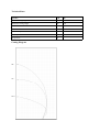
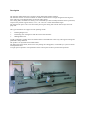
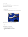
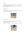
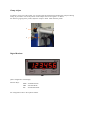
PANIMAC srl
Bladio 450
User Manual
Technical Data
Specifics
U.M.
450
Minium Cutting length
Mm
200
Maximum Cutting length
Mm
4000
Blade diameter
Mm
450
Blade Shaft diameter
Mm
30
Blade motor powe
Kw
1.15
Motor Rpm
Rpm
2800
Air pressure
Bar
6
Cutting Diagram
90°
45°
22.5°
Machine use
The machine model Bladio 450 has been designed and built to carry out cutting of PVC and Aluminium
profiles, so it is not permissible to use the machine to cut other types of material, a use other than intended may cause damage to the means of work and pose a hazard to the operator. As for the foreseeable
misuse, it recommends:
- Consider the size of the section of the aluminum or PVC, and relate it to the power of the engine blade
that you have available.
- Do not use the machine for cutting profiles that do not fall within the specified maximum cutting capacity in the cutting diagram.
General Rules of Safety
- The ordinary and extraordinary maintenance must be performed when the machine is stopped and disconnected from the sources of electric and pneumatic power.
- Any work on the hydraulic or pneumatic systems are made only after you have downloaded the pressure inside the system.
- Repairs to electrical equipment must be carried out in the absence of voltage, and with the emergency
button pressed.
- The replacement of the blades must never be carried when the machine is working or moving.
- Do not put foreign objects into moving parts and containers of liquids near the electrical parts.
- The workplace must be kept clean and tidy.
- Is strictly prohibited remove/ alterate of the safety devices.
- The operator is recommended the use of protective devices for the protection of the noise.
- We recommend the operator the use of suitable clothing to the work environment.
Description
The machine model Gladio 450 is used for cutting aluminum profiles and PVC.
The machine consists of a base in tubular on which are fixed two bars in high strength steel having functions of driving, in the displacement, the unit movable cutting.
Two cutting units, mounted on its trolleys, are constituted by a door assembly blade that can be positioned,
respect to the profiles support surface, to 45 °, 90 ° and 135 ° and at intermediate angles.
The length of the piece to be cut is achieved by moving the cutting unit with the aid of a flyer and a display unit.
This type of machine can support several operating modes:
•
•
•
Running Singles Cuts.
Performing cuts of length less than the extent of the machine.
Making Blunt Cuts.
A hydro-pneumatic cylinder drives the advancement of the blade that comes only with engine running and
pmeumatic clamps blocked.
The profile is cut by blades with carbide cutters.
The lubrication of the blade, which occurs only during the cutting phase, is obtained by a system "Venturi"
with adjustable flow.
A single operator placed in correspondence of the control panel is able to perform the operations.
Safety Device
Description
Functionality
Carter Protection Fixed
•
•
Carter Motor Protection blade holder.
Carter blade protection
Carter Furniture Protection
•
Blade Cover during work phase
Emergency stop device
•
Located on the control panel, when pressed
stops all machine functions
Electro pneumatic safety
•
Valve Minimum pressure: Stop functions
when the pressure drops below 4 Bar
The low pressure valve: allows you to have
the locking clamps profile 2 bars until the
operator is preparing to use the 2-hands.
Servo valve one way mounted on Clamp Cylinders: keep locked the profile also in case
pressure fails.
•
•
Control devices
•
•
•
•
Need to use two hands to activate the work
cycle.
Continuous activation during the working
phase.
Cycle Interruption when released one of the
control devices.
Necessity of the release of both control devices for the beginning of a new cycle of work.
Consolle
B
C
A
D
E
F
H
A Startup / Shutdown Left Motor
B Line Lamp
C Illuminated pushbutton running general
D Startup / Shutdown Right Motor
E Open / Close Clamps
F Tilt Left Head
G Tilt Right Head
H Enable tilt heads / start cycle
I Emergency Button
J Operator presence switch / start cycle
K Cut mode selector
G
I
K
J
Preventive checks
Put the power switch in position "1", the line lamp will turn on, make sure that the lamp is turned
on.
•
•
•
•
Check that the air pressure is as prescribed.
Check the oil level lubrication blade.
Press the start button and generally make sure it stays on.
(Left Cutting Switch and Inizialize Button)
Clamp Control: turn off the taps on / off of the vertical clamps, close the clamps and make sure that
the horizontal work. Wanting to use the clamps horizontal and vertical and better position them so
that they do not interfere with each other.
Control of the exact direction of rotation blade
•
•
•
•
•
Release the emergency button.
Press the start button general.
Start one of the 2 motors and Turn it off quickly.
Check the direction of rotation from the front slit during the slowing down of the blade.
Do the same for the other engine.
Blades output control
•
•
•
•
•
Proceed as described for the start of the engines.
Operate the switch to close the clamps.
Operate the switches Cycle Start and Operator Presence.
Check the correct output of the blades.
Release only one of the switches to stop the cycle.
Tilting head
In case you need tilt head follow these steps:
Select the cutting mode “0” and start operation:
•
•
Operate the switch Enable tilt heads / start cycle
Operate the switches for tilt your head at desidered inclination
Initial Settings
Tilting head cut at intermediate angles
In case you need to make cuts inclination between 45 ° and 90 ° follow these steps:
Select the cutting mode “0” and start operation:
•
•
•
•
•
•
Operate the switches for tilt your head at 45 °
Release the "c " lever
Place the reference pin reading the angle on the graduate scale "e"
Lock the "c" lever
Re-apply selectors inclination to move the head to the desired gradation
To restore the standard angles steps again by moving the lock bolt against the stop of 90 °
e
c
d
NOTE: Unlock the “c” lever only when the heads are inclined at 45 °
Tilting head cut at 22.5 °
In case you need to make cuts to 22.5 ° inclination:
Select the cutting mode “0” and start operation:
•
•
•
•
Operate the switches for tilt your head at 90°
Turn the knob "d" to delete batting 45 °
Re-apply selectors inclination to move the head to 45 °
To restore the standard angles steps again by moving the head to 90 ° and restore the beats of the
45 °
Profile Lock
Before locking the profile is necessary to adjust the position of the clamps to allow for a tight fit. The profile must be inserted from the right side to the left until at the exit slot of the blade of the head left.
The clamps remain clamped for the duration of the cut.
If the cut of certain profiles does not require the use of vertical vices you can exclude it by adjusting the
taps on / off of the vertical clamps.
Adjusting Lubricant
The lubrication of the blade is done through the venturi system and comes into operation during the cutting cycle. It can adjust the amount of liquid lubricant, by actuating the screw "a".
To exclude the lubrication close completely.
a
Adjust Blade Speed
Is possible to vary the speed of advancement acting on the screws "b" placed on the heads.
Rotate clockwise to decrease the speed or vice versa to increase it.
It is recommended to calibrate in the same way the speed of advancement of the two cutting units with a
slight predominance of the fixed blade.
ATTENTION: The speed should be adjusted according to the thickness and size of the profile to be cut.
b
Clamp Adjust
To obtain a precise cut of the profile, it is necessary that the clamps firmly blocking the workpiece during
cutting. If you need to correct the position of the clamps must act on registers "a" and "b".
For effective gripping of the profile, adjust the clamps to about 10mm from the profile.
a
b
Digital Readout
Quote configurable visual display.
Function Keys:
Mode - Inch/Mm Switch
ABS - Absolute Mode
INC - Incremental Mode
For configuration refer to the separate manual.
Cutting Operations
Cutting
•
•
•
•
•
Select the mode of cut (cutting position selector Central 0)
Start one or both engines
Operate the switch to close the clamps
Operate the switches Cycle Start and Operator Presence
Release the selectors when the blade has reached the desired depth of cut
Short Cut
•
•
•
•
•
•
•
•
•
•
•
•
•
Select the mode of cut (Short Cut)
The left blade automatically moves at 135 °
Operate the switch to close the clamps
Operate the switches Cycle Start and Operator Presence
Release the selectors when the blade has reached the desired depth of cut
At this point it will open only one of the two clamps( Fixed Head )
Unlock the brake
Switch in INC mode(incremental) and navigate to the desired quote
Block the brake for go next Step
Unlock the brake again for position operation
Block the brake for go in cut
Operate the switches Cycle Start and Operator Presence
Release the selectors when the blade has reached the desired depth of cut
Blunt Cut
•
•
•
•
•
•
•
•
•
•
Select the mode of cut (Blunt Cut)
Select Blunt side positioning Head ange 90°, is not possible start cut is both angle are 90° or 45°
Start one or both engines
Operate the switch to close the clamps
Operate the switches Cycle Start and Operator Presence
Release the selectors when the blade has reached the desired depth of cut
Unlock the brake and navigate to the desired quote
Block the brake for go in cut
Operate the switches Cycle Start and Operator Presence
Release the selectors when the blade has reached the desired depth of cut
Selector Management
Maintenance and Repair
Important: the operations described in the various paragraphs, are to be made strictly with the machine
switched off and disconnected from the sources of energy (electrical and pneumatic).
In case you are not able to riscontrarne the problem, contact the manufacturer for assistance.
Line Lamp does not work
•
•
•
•
Check that the machine is connected to the electric current
Check that the main switch is on position "1"
Check that the bulb of the lamp is not burned out, replace it if necessary
Check fuses phase
The car does not go into gear
•
•
•
•
•
Check that the line lamp is on
Check that the emergency stop button is not pressed
Check that the air pressure is as required
Check that the fuses are intact, otherwise replace them with unplugged network cable.
There are irregularities in the angles
Before proceeding with the operation of angle calibration remove any dirt from the cutting plane and checked for proper workpiece clamping. If the problem persists contact your service support.
Irregularities of cut at 90 °
Put the profile within a precision steel square, using the same base served for cutting, to check the irregularities.
In case of having to perform operations of adjustment:
•
Bring the cutting unit to 45 °
•
If the cut has an angle > 90° unscrew the screw and secure it with the nut
•
If the cut has an angle< 90° tighten the screw and secure it with the nut
•
Adjusting Screw
Irregularities of cut at 45 °
Place the two pieces of profile, using the same support base served for cutting, and use a precision square
for verifying the irregularities.
In case of having to perform operations of adjustment:
•
Bring the cutting unit to 90 °
•
If the cut has an angle > 45° tighten the screw and secure it with the nut
•
If the cut has an angle < 45° unscrew the screw and secure it with the nut
Vite Regolazione
Irregularities of the cut to 135 °
Place the two pieces of profile, using the same support base served for cutting and use a precision square
for verifying the irregularities.
In case of having to perform operations of adjustment:
•
Bring the cutting unit to 90 °
•
If the cut has an angle > 22,5° tighten the screw and secure it with the nut
•
If the cut has an angle < 22,5° unscrew the screw and secure it with the nut
Vite Regolazione
NOTE: Repeat the operation several times with the cutting head concerned, to determine the exact angle
Blades do not come out
•
•
•
Check that the motors are turned on and their lamps are lit on the keypad
Check that you have performed the locking clamps
Check for proper operation and placement of the protections micro
Automatic clamps open do not work at cycle end
•
•
•
Check position for blades limit swith.
Clean the switch area from dirt
Check for proper operation of the micro switch blade
Blade limit switch
Pneumatic system problem
If some function of the cutting cycle should not be performed, to determine if the cause is pneumatic or
electric, you can perform a check on the correct operation of the pneumatic valves, acting directly on
them. It is possible to manually drive the pneumatic valve, acting on the cylinder placed on the head of the
valves near the coils. Press the button to operate the valve.
A - Output Left Blade
B - Output Right Blade
C - Protections Control
D - 90 ° tilting Fixed Head
E - 45 ° tilting Fixed Head
F - 90 ° Tilting Head Mobile
G - 45 ° Tilting Head Mobile
H - Brake command
I - Open Fixed Head Clamp
J - Close Fixed Head Clamp
K - Open Moving Head Clamp
L - Close Moving Head Clamp
A
B
C
D
E
F
G
H
I
J
K
L
For other problems not found in the manual or in case you are not able to resolve the problem, contact
Technical Support.
Panimac Srl - Viale Alfredo Binda, 20 - 80040 Cercola(Na) - Tel 081-5550783