1
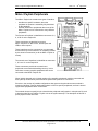
This document is the property of Aardvark Embedded Solutions Ltd and may not be reproduced in part or in total
by any means, electronic or otherwise, without the written permission of Aardvark Embedded Solutions Ltd.
Aardvark Embedded Solutions Ltd does not accept liability for any errors or omissions contained within this
document. Aardvark Embedded Solutions Ltd shall not incur any penalties arising out of the adherence to,
interpretation of, or reliance on, this standard. Aardvark Embedded Solutions Ltd will provide full support for this
product when used as described within this document. Use in applications not covered or outside the scope of
this document may not be supported. Aardvark Embedded Solutions Ltd. reserves the right to amend, improve
or change the product referred to within this document or the document itself at any time.
Milan / Paylink Configurable Driver Manual
Issue 1.2
th
24 April 2012
Table of Contents
Table of Contents.............................................................................................................................. 2
Revision History ................................................................................................................................ 3
Introduction ....................................................................................................................................... 4
Purpose of Document.................................................................................................................... 4
Intended Audience......................................................................................................................... 4
Associated Document(s) ............................................................................................................... 4
Document Layout .......................................................................................................................... 4
Milan / Paylink Peripherals................................................................................................................ 5
System Structure............................................................................................................................... 6
Configuration File .............................................................................................................................. 7
DRIVER Details ............................................................................................................................. 8
SYSTEM Details............................................................................................................................ 9
PROTOCOL Details .................................................................................................................... 10
CCTALK Device Definition .......................................................................................................... 11
MDB Device Definition ................................................................................................................ 12
F53/F56 Cassette Definition........................................................................................................ 13
Original Paylink Definition. .......................................................................................................... 13
Disclaimer ....................................................................................................................................... 14
CONFIDENTIAL
Not to be disclosed without prior written permission from Aardvark Embedded Solutions Ltd
Page 2 of 14
Milan / Paylink Configurable Driver Manual
Issue 1.2
th
24 April 2012
Revision History
Version
1.0
1.1
1.2
Date
th
7 Oct 10
12 Feb 12
24th April 12
Author
D Bush
D Bush
D Bush
Description
First release
Updated for 1.12.3
Updated for 1.12.4
CONFIDENTIAL
Not to be disclosed without prior written permission from Aardvark Embedded Solutions Ltd
Page 3 of 14
Milan / Paylink Configurable Driver Manual
Issue 1.2
th
24 April 2012
Introduction
Purpose of Document
This document describes the structure of a system using the AES Intelligent Money Handling
Equipment Interface (Milan / Paylink), with specific reference to the Paylink or AESCDriver program
that is an integral part of this system.
Intended Audience
The intended audience of this document is the software engineers who will be configuring the PC that
will communicate with the Paylink unit itself and run the users application.
Associated Document(s)
Full details of the application interface to the Milan / Paylink unit are given in the associated
document, “Milan / Paylink Applications Interface User Manual”.
Document Layout
The document itself is split into a number of sections:
1. Milan / Paylink peripherals
This section gives the background on how Milan / Paylink handles the peripherals to which it
can be connected.
2. System structure
This provides a description of how the DLL and the driver program co-operate with the
Milan / Paylink unit over the USB cable.
3. Configuration File
This describes the configuration file that is required on Paylink firmware releases after
1.12.1 / 25.12.1
CONFIDENTIAL
Not to be disclosed without prior written permission from Aardvark Embedded Solutions Ltd
Page 4 of 14
Milan / Paylink Configurable Driver Manual
Issue 1.2
th
24 April 2012
Milan / Paylink Peripherals
The Milan / Paylink unit contains two types of interface:
•
•
Interfaces to specific hardware, where the
peripheral in question is essentially fully described
by the hardware.
General interfaces to peripherals where one of the
Milan / Paylink can be connected to many different
peripherals.
The first sort of interface is identified as connectors 3, 4,
6, 10 & 12 on the Paylink lid.
These connectors are provided to connect
Milan / Paylink to an SEC meter, switch inputs and
LEDs or other outputs.
These interfaces may be connected or not connected,
but the item they are connected to is completely defined
by the electrical connection (so far as Milan / Paylink is
known)
The second sort of interfaces is identified as connectors
1, 8, 9 and 11 on the Paylink lid.
These connectors provide the connections to
peripherals concerned with handling currency. In this
case there are many possible peripherals that can be
connected to the Milan / Paylink unit.
When initially released only a limited number of the possible peripherals could be connected and
three (later 4) variants were produced which specified the protocol on connector 9.
Since then, the number of possible configurations has grown to the point where some method is
needed to tell Milan / Paylink details about where to look for specific peripherals, and how it should
regard those peripherals when it found them.
The method chosen to specify this is to describe the peripheral configuration in a simple text file, and
to download that file to the Milan / Paylink unit as the system starts up. The description of this file is
prime purpose of this document.
CONFIDENTIAL
Not to be disclosed without prior written permission from Aardvark Embedded Solutions Ltd
Page 5 of 14
Milan / Paylink Configurable Driver Manual
Issue 1.2
th
24 April 2012
System Structure
A system that uses a Milan / Paylink unit comprises a users application that communicates via a DLL
to the Milan firmware installed on the Milan / Paylink unit.
As the Milan / Paylink unit is connected to the PC by a USB cable, there has to be software at both
ends of this USB link to conduct the communications over the link.
At the Milan / Paylink end this communications software is just built into the firmware. At the PC end
the communications software run as a separate Windows item.
In the theoretical model of the Milan / Paylink system there were originally intended to be two options
for this, a normal windows service, installed and managed in the same way as for other services and
as an alternative a Windows program, AESWDriver.exe.
In practice the service option was never completed, and all Milan / Paylink installations prior to
release 1.12.1 / 25.12.1 have used the AESWDriver.exe.
The expected use of the driver program is that during initial program development, the driver is run
and the program window is referred to in order to monitor and control the connection to the
Milan / Paylink. When the system approaches a live configuration the driver program is run silently
with a log file being produced for incident investigation. Finally, the launch of the driver is placed into
the system start up files
With this release of the Milan / Paylink system, this original program has now been superseded by a
new configuring driver program which is available in two distinct forms: Paylink.exe which only runs
under Windows where it also supports USB peripherals made by MCL and AESCDriver.exe, the
generic driver program, primarily used on Linux.
This new program is an enhancement of the original driver, which allows for the comprehensive
tailoring of a Milan / Paylink system to the requirements of the individual user.
When Paylink.exe / AESCDriver.exe is run it needs to read in a configuration. The path to the
configuration file can be provided as a single parameter, if no parameter is provided then it will try to
read the file “standard.cfg” in the folder from which it is run.
The exact configuration of the driver program itself can be accomplished by two means, with identical
results.
On the command line itself, switch parameters can be used, as follows:
/S <Paylink Serial> is used in multiple Paylink installations, and specifies the serial number of the
Paylink device that this driver is to connect to.
/L <Log File Name> is the full path to the desired log file.
/Z <K Bytes>
is the maximum size the log file is allowed to reach. If it reaches this size, then
it is renamed with a “.old” extension added and a new file started. If omitted,
the maximum size is 128K bytes.
/H
if this is used no window or taskbar Icon are displayed.
/V
if this is used a normal window is shown on the screen.
CONFIDENTIAL
Not to be disclosed without prior written permission from Aardvark Embedded Solutions Ltd
Page 6 of 14
Milan / Paylink Configurable Driver Manual
Issue 1.2
th
24 April 2012
Configuration File
The single parameter to Paylink.exe / AESCDriver.exe is a simple text file, containing a set of
keywords and values that describe the configuration of the Paylink. Line ends are never significant,
and anything on a line after a slash (/) character is ignored.
This section describes the make up of a configuration file. In the following description:
UPERCASE
words represent keywords, which must be spelt as shown, but can be in any case.
[ Optional]
sections are enclosed in square brackets and represent sections that can be
included either to give further details on the item, or to make the “English” read
better.
< Values >
are enclosed in angle brackets. Values can be number expressed in decimal or
hex, or, in some cases, can be pre-defined keywords that map onto numbers. A
string of digits is held to be decimal number, hex numbers can either start with 0x or
end in H.
|
Shows that one of the two values on either side if the symbol must be included.
There are three top level keywords:
PROTOCOL
- Which describes the peripherals connected to one of the Paylink’s 4 serial ports.
SYSTEM
- Which defines the ways in which the overall running of Paylink is modified.
DRIVER
- Which gives the driver itself details on how it should run.
CONFIDENTIAL
Not to be disclosed without prior written permission from Aardvark Embedded Solutions Ltd
Page 7 of 14
Milan / Paylink Configurable Driver Manual
Issue 1.2
th
24 April 2012
DRIVER Details
The DRIVER keyword introduces a section of configuration to control the driver program itself:
RUN HIDDEN | VISIBLE
This controls the Driver window (independently from the presence of a log file)
• If HIDDEN is specified, then no window or taskbar Icon are displayed.
• If VISBLE is specified, then a normal window is shown on the screen.
• If the item is omitted, then a Taskbar Icon appears, but the window is minimised.
LOGFILE “<Name>” [SIZE <K bytes>]
This specifies that a log file is to be generated.
<Name> is the full path to the desired log file, the “ symbols are compulsory even if there are
no spaces in the name.
<K Bytes> is the maximum size the log file is allowed to reach. If it reaches this size, then it is
renamed with a “.old” extension added and a new file started.
If SIZE is omitted, the maximum size is 128K bytes.
SERIAL [NUMBER} <Paylink Serial>
This is used in multiple Paylink installations, and specifies the serial number of the Paylink
device that this driver is to connect to.
CONFIDENTIAL
Not to be disclosed without prior written permission from Aardvark Embedded Solutions Ltd
Page 8 of 14
Milan / Paylink Configurable Driver Manual
Issue 1.2
th
24 April 2012
SYSTEM Details
The SYSTEM keyword introduces a section of overall configuration, which includes one or more of:
SIMULTANEOUS HOPPERS <Count>
Earlier versions of Paylink would only run a single hopper at a time in order to protect the
power supplies. If an installation has the ability to run multiple hoppers at once, then this
parameter can be used to increase the number of simultaneously running hoppers.
WATCHDOG [On] [OUTPUT] <Pin>
The CheckOperation() facility already allows Paylink to discover that PC application is no
longer in contact, and to inhibit all the peripherals. This entry causes output <pin> on the
Paylink to be driven only when Paylink is in normal operation, to allow for the control of
arbitrary external equipment.
POWER ON [ON] [OUTPUT] <Pin> DELAY <MSec>
To allow for the power on sequencing of the elements within a cabinet, this allows the Paylink
device to control an output that turns on a specific time after the Paylink powers up. This
entry causes output <pin> on the Paylink to be driven <Msec> milliseconds after the Paylink
itself powers up.
MECHANICAL METER <Meter No> [ON] [OUTPUT] <pin>
This entry can repeated up to 8 times. Each entry defines to the Paylink meter functionality
that a mechanical meter <Meter No> is connect to output <Pin>. (More details are in the API
document.)
POWER FAIL [ON] [INPUT] <Pin>
This does not appear anywhere in the API. If used, this is a connection that should short this
pin to ground whenever the power supply is satisfactory, and go open circuit as soon as
there is a problem. This input is used in two places:
1. As soon as this output triggers, all acceptors are disabled. This primarily allows coin
acceptors to reject coins that will not complete correct acceptance before the power fails
complete.
2. The mechanical meter processing will not start a pulse if this input is not satisfactory.
This removes the possibility of a pulse being cut short by a power failure.
CONFIDENTIAL
Not to be disclosed without prior written permission from Aardvark Embedded Solutions Ltd
Page 9 of 14
Milan / Paylink Configurable Driver Manual
Issue 1.2
th
24 April 2012
3. PROTOCOL Details
PROTOCOL <Name> [ON] CONNECTOR <Connector>
This introduces a section describing the usage of the named protocol on the specified
connector. The Connector is specified by its identity on the lid of the Paylink, and is one of
the following:
CCTALK or 8
- The six way connector near the USB cable.
MDB or 1
- The three way Molex KK at the other end to the USB cable.
RJ45 or ARDAC or 9 - The RS232 RJ45 connector near the USB cable.
GEN2 or RS232 or 11 - The RS232 seven way Molex KK connector on the long side.
Note: The cctalk and MDB protocols are usually used together with unique electrical levels on the
connection. Paylink provides these levels on the relevant connectors and so it would be unlikely that
these would specify other than the dedicated connector - but doing so is perfectly valid.
Specific protocols that can be defined are:
PROTOCOL ID003 [ON] CONNECTOR <Connector> [WITH] ACCEPTOR | RECYCLER
This connection will be to a single unit, either a note acceptor or a recycler using the JCM
ID_003 extensions. . - no further configuration is possible.
PROTOCOL GEN2 [ON] CONNECTOR <Connector>
This connection will be to a Gen 2 ticket printer. - no further configuration is possible.
PROTOCOL CCTALK [ON] CONNECTOR <Connector>
This starts the definition of a network of cctalk devices. More information on this network is
given below.
PROTOCOL CCNET [ON] CONNECTOR <Connector>
This starts the definition of an addressable CCNet device. More information is given below.
PROTOCOL MDB [ON] CONNECTOR <Connector>
This starts the definition of a network of MDB devices. More information on this network is
given below.
PROTOCOL F53 [ON] CONNECTOR <Connector> DELIVERY [AT] NONE | FRONT | REAR
PROTOCOL F56 [ON] CONNECTOR <Connector> DELIVERY [AT] NONE | FRONT | REAR
This connection will be to a single Fujitsu F56 family bill / note dispenser.
Paylink requires the specification of the note delivery system, so as to know whether to issue
a delivery command, and which one.
The cassettes for this unit can optionally be configured. More information on this is given
below.
CONFIDENTIAL
Not to be disclosed without prior written permission from Aardvark Embedded Solutions Ltd
Page 10 of 14
Milan / Paylink Configurable Driver Manual
Issue 1.2
th
24 April 2012
CCTALK Device Definition
The cctalk protocol handler supports a potentially large number of note / bill acceptor, coin acceptor
and payout devices. Following the introductory PROTOCOL entry, all the ccctalk devices in use on
this installation have to be defined, as follows:
COIN [ACCEPTOR] [AT] <Address> [BNV <Key>] [CRC]
This specifies that a coin acceptor is to found at the specified cctalk <Address>, and may
specify that BNV encryption with the given key and / or that CRC message validation is used.
Normally cctalk coin acceptors are at address 2, and do not use BNV or CRC messages.
NOTE [ACCEPTOR] [AT] <Address> [BNV <Key>] [CRC]
BILL [ACCEPTOR] [AT] <Address> [BNV <Key>] [CRC]
This specifies that a note / bill acceptor is to found at the specified cctalk <Address>, and
may specify that BNV encryption with the given key and / or that CRC message validation is
used.
Normally cctalk note / bill acceptors are at address 40 (28H), use a BNV key of 123456 and
use CRC message validation.
<Type> RECYCLER [AT] <Address> [BNV <Key>] [CRC]
This specifies that a note / bill recycler is to found at the specified cctalk <Address>, and may
specify that BNV encryption with the given key and / or that CRC message validation is used.
As there is no standard specification for controlling recycler, the <Type> also has to be
specified. A <Type> from the following list can be used:
MERKUR
- A recycler using the same commands as the Merkur MD100 device.
VEGA
- A recycler using the same commands as the JCM Vega unit
NV11
- A recycler using the same commands as the Innovative NV11
NV200
- A recycler using the same commands as the Innovative NV200
HOPPER [AT] <Address>
This specifies that a coin hopper is to found at the specified cctalk <Address>, and may
specify that BNV encryption with the given key and / or that CRC message validation is used.
Normally cctalk hoppers are at addresses that start at 3 and increase as more hoppers are
added. MCL hoppers can be addresses from 3 to 10.
Hoppers require a significant amount of configuration. Any combination of the following
keywords in any order can be used.
Note that there are three different ways to specify the coin value - any combination can be
used, but Paylink will not use a hopper which a value has not been obtained. (This may be a
desired operational mode.)
[VALUE <Coin Value>]
Specifies the (default) value in pence of the coins in this hopper. If neither of the following
two options are used, then this value is fixed.
[OVERRIDE YES]
Specifies the any value set up during initialisation can be overridden by the application
changing the coin value. If this is not specified, any application originated change will be
ignored.
[READOUT VALUE]
Specifies that the Hopper Eprom will be read during initialisation and any coin value found
will be used instead of the default (if any) established by the <Coin Value> entry.
[AZKOYEN]
CONFIDENTIAL
Not to be disclosed without prior written permission from Aardvark Embedded Solutions Ltd
Page 11 of 14
Milan / Paylink Configurable Driver Manual
Issue 1.2
th
24 April 2012
The detailed implementation of cctalk commands differs between Money Controls and
Azkoyen. This keyword forces Azkoyen specific processing of the hopper. If the hopper
replies to the relevant initialisation message with a Manufacturer starting “Azk” then this
processing is selected automatically.
[TIMEOUT <Count>]
This specifies that the cctalk header 165 (Modify Variable Set) be used to change the
“payout timeout” value from its default of 10 seconds to <Count> periods of 1/3 second.
This is unlikely to work on hoppers not made by Money Controls.
Examples
Hopper at 03 Value 100
Hopper at 03 Readout Value
- is a hopper whose value is guaranteed to be 100
- is a hopper that is unusable unless a coin value can be
read out.
Hopper at 03 Override Yes
- is a hopper that is unusable unless the application sets a
coin value
Hopper at 03 Value 100 Azkoyen - is a hopper which will be unconditionally use the Azkoyen
protocol variations.
Existing System
The equivalent definitions to the original Paylink configuration are given further on.
MDB Device Definition
The MDB protocol allows for two changer devices and for two bill acceptors. This section states
which are used:
CHANGER [AT] <Address>
This specifies that a coin changer is to found at the specified MDB <Address).
Normally MDB coin changers are at <Address> 08H
NOTE [ACCEPTOR] [AT] <Address>
BILL [ACCEPTOR] [AT] <Address>
This specifies that a note / bill acceptor is to found at the specified MDB <Address).
Normally MDB note / bill acceptors are at <Address> 30H
CONFIDENTIAL
Not to be disclosed without prior written permission from Aardvark Embedded Solutions Ltd
Page 12 of 14
Milan / Paylink Configurable Driver Manual
Issue 1.2
th
24 April 2012
F53/F56 Cassette Definition
F53/F56 cassettes are identified by one or two magnets fitted into the case that identify the bills /
notes that are loaded into the cassette. This section allows for this specification:
CASSETTE [AT] <Identity> VALUE <Value> [MAX <Max>] [MIN <Min>]
[THICKNESS] <thickness>]
This specifies that the cassette with the given magnet <Identity> contains bills / notes with
the given value (in cents / pence).
Paylink will default to allowing any size note to be accepted, but for added security correctly
encoded length and thickness bytes <Max>, <Min> and <thickness > can optionally be
specified and will be sent to the F53/F56 during cassette initialisation.
Examples
F56 cassettes typically contain two magnets, and so a common standard configuration uses
the six two bit numbers:
Cassette 3 Value 10000
Cassette 5 Value 5000
Cassette 6 Value 2000
Cassette 9 Value 1000
Cassette 10 Value 500
Cassette 12 Value 100
Less common are one magnet, but an alternative set uses the four one bit numbers:
Cassette 1 Value 10000
Cassette 2 Value 1000
Cassette 4 Value 500
Cassette 8 Value 100
Original Paylink Definition.
The definitions required to reproduce the original Paylink configuration are:
Protocol cctalk on connector cctalk
Coin Acceptor at 2
Note Acceptor at 40 BNV 123456
Hopper at 3 Value 100 Override
Hopper at 4 Value 40 Override
Hopper at 5 Value 25 Override
Hopper at 6 Value 20 Override
Hopper at 7 Value 10 Override
Hopper at 8 Value
5 Override
Hopper at 9 Value 200 Override
Hopper at 10 Value 1 Override
CRC
Yes
Yes
Yes
Yes
Yes
Yes
Yes
Yes
Readout
Readout
Readout
Readout
Readout
Readout
Readout
Readout
Value
Value
Value
Value
Value
Value
Value
Value
Protocol ID003 on connector RJ45
Protocol GEN2 on connector 11
Protocol MDB on connector MDB
Changer at 08H
Bill at 30H
CONFIDENTIAL
Not to be disclosed without prior written permission from Aardvark Embedded Solutions Ltd
Page 13 of 14
Milan / Paylink Configurable Driver Manual
Issue 1.2
th
24 April 2012
Disclaimer
This manual is intended only to assist the reader in the use of this product and
therefore Aardvark Embedded Solutions shall not be liable for any loss or damage
whatsoever arising form the use of any information or particulars in, or any incorrect
use of the product. Aardvark Embedded Solutions reserve the right to change
product specifications on any item without prior notice
CONFIDENTIAL
Not to be disclosed without prior written permission from Aardvark Embedded Solutions Ltd
Page 14 of 14


![TSP050 SCH2 User Manual V1[1].](http://vs1.manualzilla.com/store/data/005912572_1-7a45ce84788ca8c84bf3ae15dae5a757-150x150.png)