1
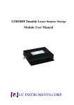
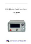
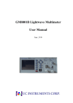
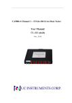
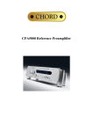
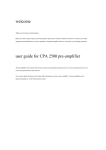
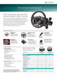
GM8015 Polarization Controller
User Manual
GM8015 Polarization Controller User Manual V2.11
Notices
This document contains UC INSTRUMENTS CORP. proprietary information that is
protected by copyright. All rights are reserved. This document can’t be reproduced in
(including electronic storage and retrieval or translation into a foreign language)
without prior agreement and written consent from UC Instruments Corp.
Subject Matter
The material in this document is subject to change without notice.
UC Instruments Corp. makes no warranty of any kind with regard to this printed
material, including, but not limited to, the implied warranties of merchantability and
fitness for a particular purpose.
UC Instruments Corp. shall not be liable for errors contained herein or for incidental or
consequential damages in connection with the furnishing, performance, or use of this
material.
Warranty
This UC Instruments Corp. product is warranted against defects in material and
workmanship for a period of 12 months from date of shipment. During the warranty
period, UC INSTRUMENTS CORP. will, at its option, either repair or replace products
that prove to be defective.
For warranty service or repair, this product must be returned to a service facility
designated by UC Instruments Corp. Buyer shall prepay shipping charges to UC
Instruments Corp. and UC Instruments Corp. shall pay shipping charges to return the
product to Buyer. However, Buyer shall pay all shipping charges, duties, and taxes for
products returned to UC Instruments Corp. from another country.
UC Instruments Corp. warrants that its software and firmware designated by UC
Instruments Corp. for use with an instrument will execute its programming instructions
when properly installed on that instrument. UC Instruments Corp. does not warrant that
the operation of the instrument, software, or firmware will be uninterrupted or error
free.
10210004 R001
www.ucinstruments.com
1
GM8015 Polarization Controller User Manual V2.11
Limitation of Warranty
The foregoing warranty shall not apply to defects resulting from improper or
inadequate maintenance by Buyer, Buyer-supplied software or interfacing,
unauthorized modification or misuse, operation outside of the environmental
specifications for the product, or improper site preparation or maintenance.
No other warranty is expressed or implied. UC Instruments Corp. specifically disclaims
the implied warranties of Merchantability and Fitness for a Particular Purpose.
Exclusive Remedies
The remedies provided herein are Buyer’s sole and exclusive remedies.
UC Instruments Corp. shall not be liable for any direct, indirect, special, incidental, or
consequential damages whether based on contract, tort, or any other legal theory.
Assistance
Product maintenance agreements and other customer assistance agreements are
available for UC Instruments Corp. products. For any assistance contact the UC
Instruments Corp. Maintenance Service Center.
Safety Considerations
The following general safety precautions must be observed during all phases of
operation, service, and repair of this instrument. Failure to comply with these
precautions or with specific warnings elsewhere in this manual violates safety standards
of design, manufacture, and intended use of the instrument. UC Instruments Corp.
assumes no liability for the customer’s failure to comply with these requirements.
10210004 R001
www.ucinstruments.com
2
GM8015 Polarization Controller User Manual V2.11
General
This is a Safety Class 1 instrument (provided with a protective earth terminal) and has
been manufactured and tested according to international safety standards.
Before operation, you should review the instrument and manual for safety markings and
instructions. You must follow these to ensure safe operation and to maintain the
instrument in safe condition.
WARNING: To avoid hazardous electrical shock, do not perform electrical tests
when there are signs of shipping damage to any portion of the outer enclosure (covers,
panels, and so on).
Operating Environment
WARNING: The GM8015 polarization controller is not designed for outdoor use. To
prevent potential fire or shock hazard, do not expose the instrument to rain or other
excessive moisture.
WARNING: To avoid the possibility of injury or death, you must observe the
following precautions before switching on the instrument.
z
Insert the power cable plug only into a socket outlet provided with a protective
earth contact. Do not negate this protective action by the using an extension cord
without a protective conductor.
z
Do not interrupt the protective earth connection intentionally.
z
Do not remove protective covers. Operating personnel must not remove instrument
covers. Component replacement and internal adjustments must be made only by
qualified service personnel.
z
Instruments that appear damaged or defective should be made inoperative and
secured against unintended operation until they can be repaired by qualified service
personnel.
z
Defective, damaged, or malfunctioning laser sources must be returned to UC
Instruments Corp. Maintenance Service Center.
z
Do not operate the instrument in the presence of flammable gases or fumes.
Operation of any electrical instrument in such an environment constitutes a definite
safety hazard.
10210004 R001
www.ucinstruments.com
3
GM8015 Polarization Controller User Manual V2.11
CONTENT
Summarize ............................................................................................................. 6
Features.................................................................................................................. 6
Specifications ......................................................................................................... 7
Description of the User Interface......................................................................... 7
Push Buttons ......................................................................................... 8
Optical input and output connectors ..................................................... 8
AC Line Power Supply Requirements ................................................................ 8
Line Power Requirements..................................................................... 8
Line Power Cable.................................................................................. 8
Communication Interface .................................................................................... 9
RS232 Serial Interface Port .................................................................. 9
Fixed Parameters.......................................................................... 9
RS232 Connector .................................................................................. 9
Cable ..................................................................................................... 9
How to Modify the Display?............................................................................... 10
Initialization the Display Screen......................................................... 10
The Display Screen ............................................................................. 10
How to Use the GM8015?................................................................................... 11
Theory of Operation............................................................................ 12
Using the GM8015 Polarization Controller........................................ 12
How to transfer control mode? ........................................................... 13
How to adjust the position of paddle?................................................. 13
How to continuously sweep all polarization states? ........................... 13
Set the scan rate.......................................................................... 13
10210004 R001
www.ucinstruments.com
4
GM8015 Polarization Controller User Manual V2.11
Perform the Auto scan operation................................................ 14
How to reset the positions of paddles to zero? ................................... 14
How to unlock the remote control status?........................................... 14
Polarization-dependent loss measurement ....................................................... 15
Claims and Repackaging.................................................................................... 16
Return Shipments to UC Instruments Corporation............................. 16
Maintenance ........................................................................................................ 16
UC INSTRUMENTS CORP. CONTACT INFORMATION ......................... 17
10210004 R001
www.ucinstruments.com
5
GM8015 Polarization Controller User Manual V2.11
Summarize
The UC INSTRUMENTS GM8015 Polarization Controller is a program motorized
control polarization scrambler. Its polarization controlled capability enhances
measurement speed, accuracy, and overall productivity. The continuous length of fiber
enables high power and ultra-low insertion loss. This design offers a wide range of
Auto Scan rates and high incremental angular resolution. Four fiber loop design has
proven to provide excellent control with ultra-low power variations (PDL). This
reliable design allows for a wide range of applications from component testing to PMD
related activities.
Figure 1
GM8015 Polarization Controller
Features
Single-fiber design
Ultra-low insertion loss, PDL, and back-reflection
Multi-rate polarization scrambling
Auto scan operation with a wide dynamic range of rotational speed
RS-232 communication
10210004 R001
www.ucinstruments.com
6
GM8015 Polarization Controller User Manual V2.11
Specifications
Model #
GM8015
Principle
4 Motorized Fiber Loop
Wavelength Range
1200 ~ 1700 nm
Insertion Loss
< 1.0 dB
Extinction Loss
40 dB
≤ 0.01 dB
PDL
Optical Connector
FC/PC
Operating Temperature
0 ~ 40 °C
Interface
RS232
Power
100 ~ 240 V AC, 50 - 60 Hz
Operation Temperature
0~ +40℃
Storage Temperature
-30~+80℃
Dimensions
350 mm X 200 mm X 120 mm
Weight
5.3 kg
Description of the User Interface
LCD display
Power key
Push button
Optical Input
Connector
Optical Output
Connector
RS232 Port
AC Power coupler
Figure 2 - User interface of the GM8015
10210004 R001
www.ucinstruments.com
7
GM8015 Polarization Controller User Manual V2.11
Push Buttons
All the control to GM8015 is via the push buttons.
Optical input and output connectors
The GM8015 has two FC/PC connectors for optical input and output.
AC Line Power Supply Requirements
Line Power Requirements
The GM8015 polarization controller complies with over voltage category II and can
operate from the single-phase AC power source that supplies between 100V and 240V
at a frequency in the range 50 to 60 Hz.
The AC power requirements are summarized on the rear panel of the instrument.
AC INPUT:
100-240V~, 50-60Hz,
AC Power Requirement Mark - GM8015
The power key on the front panel of the GM8015 may turn on or turn off the power.
GM8015 Power Key
Line Power Cable
In accordance with international safety standards, the instrument has a three-wire power
cable.
10210004 R001
www.ucinstruments.com
8
GM8015 Polarization Controller User Manual V2.11
Communication Interface
RS232 Serial Interface Port
There is a RS232 serial interface port for communication on the rear panel of the
GM8015.
The GM8015 serial interface has fixed parameters. The PC serial interface should be
configured to match the instrument’s fixed parameters.
Fixed Parameters
These are:
Baud rate
115200
Data Bits
8
Parity
None
Stop Bits
1
RS232 Connector
The following figure shows the connector and pin assignments.
2- Transmit data
3- Received data
5-Signal ground
RS232 Connector
Cable
The connectors pin assignments on the cable for RS232 Communication.
DB9 CONNECTOR
PIN
NOTES
Received data
2
Transmit data
3
Signal ground
5
DB9 CONNECTOR
PIN
NOTES
Transmit data
2
Received data
3
Signal ground
5
NOTE For serial communication use the null modem cable provided with your
10210004 R001
www.ucinstruments.com
9
GM8015 Polarization Controller User Manual V2.11
instrument.
How to Modify the Display?
Initialization the Display Screen
When the GM8015 is powered up, the screen will show initial information, such as, the
serial number, hardware revision, firmware revision of the GM8015.
UC Instruments
GM8015 PDL Controller
SN: GG0426 21 002
Firmware: 2.00
Figure 3
The detecting information for GM8015
Then the system resets the position of fiber loop to zero, during reset, the LCD shows
“Restoration…”.
The Display Screen
After start-up, this screen will show immediately the control mode of GM8015 and the
positions of four paddles, form left to right, from one to four.
The default display shows the Automatic mode for the instrument. Pressing
[MAN/AUTO] button will transfer the control mode between Automatic mode and
Manual mode.
Auto mode
Scan rate
Status: Auto
The position of
paddle
0000
0000
Rate: 1
0000
0000
Figure 4 Display screen for Automatic mode
10210004 R001
www.ucinstruments.com
10
GM8015 Polarization Controller User Manual V2.11
In the Manual mode, when you select a fiber loop by pressing the [Select] button, the
position value for the selected paddle will be focused, and the font is increased.
Manual mode
Status: Manual
The position of
paddle
0000
0000
Step value
Step: 010
0000
0000
Figure 5 Display screen for Manual mode
How to Use the GM8015?
The GM8015 polarization controller provides Manual and Automatic polarization state
adjustments over a wide wavelength range from 1200 nm to 1700 nm. All possible
states of polarization are achieved with extremely small optical insertion-loss variations
(≤0.01dB). This feature can achieve measurement accuracy maximum for power
sensitive measurements such as polarization-dependent loss, gain and optical/electrical
responsivity because the measurement uncertainty contributed by the polarization
controller is minimized. A typical application configuration using the polarization
controller is shown in the following figure.
GM8015
10210004 R001
www.ucinstruments.com
11
GM8015 Polarization Controller User Manual V2.11
Theory of Operation
The transmitted signal enters the polarization controller and passes through the internal
four-fiber-loop assembly. The dimensions of each loop are optimized to approximate a
quarter-wave retarder response over the polarization controller’s specified wavelength
range. Complete and continuous polarization adjustability is achieved by independently
adjusting each loop over an angular range of 180°. This range is divided into 1600
equal steps (0000 - 1600), providing an adjustment resolution of 0.1125°. Adjustments
can be made manually, using the front-panel knobs, or automatically, using remote
RS232 commands.
Using the GM8015 Polarization Controller
Precise manual adjustment of the four paddles in the polarization controller can be
made using the front-panel knobs while watching the display.
Each paddle can rotate 180°in 1600 discrete steps of 0.1125°each. The LCD displays
the relative step count, where zero corresponds to 0° and 1600 corresponds to 180°.
The instrument presets four available polarization scan rates to match the speed of the
application. In Auto mode, the instrument performs automatically scan all the
polarization states with the selected scan rate until pressing the [CANCEL] button.
Remote interrogation of all instrument settings and remote control of all instrument
functions are provided via RS232 Port.
10210004 R001
www.ucinstruments.com
12
GM8015 Polarization Controller User Manual V2.11
How to transfer control mode?
Press the [MAN/AUTO] button, if the LCD displays “Status: Manual” on the top, the
module is in Manual mode. You will control the paddles from the buttons on the front
panel of the module.
Press the [MAN/AUTO] button once again, the LCD displays “Status: Auto”, the
module is in Automatic mode.
How to adjust the position of paddle?
Precisely adjust the position of paddle via the [+] and [-] buttons in Manual mode.
Each of the four paddles can now be controlled independently. Paddle positions are
displayed on the LCD. “0000” corresponds to 0°, and 1600 corresponds to 180°.
z
Press the [MAN/AUTO] to enter Manual mode.
z
Press the [Select] button continuously to select the desired paddle. When a paddle
is selected, the font of position value increases and the background is focused.
z
Pressing [Rate] transfers the step value between 1,10 and 100.
z
Press the [+] and [-] buttons to adjust the position value of the paddle in a step of
rate value.
How to continuously sweep all polarization states?
Set the scan rate
The module presets eight available polarization scan rates which are indicated with 1, 2,
3、4、5、6、7、8.
Pressing [Rate] button transfers the scan rate.
10210004 R001
www.ucinstruments.com
13
GM8015 Polarization Controller User Manual V2.11
Perform the Auto scan operation
Press [Enter] button, the module begins to sweep all the polarization states with the
selected scan rate.
The sweep can pause if you press the [Cancel] button, and pressing [Enter] button again
will continue.
How to reset the positions of paddles to zero?
Press [RECALL/SAVE] button to reset the positions of the four paddles to zero.
If the instrument is performing the Auto scan, before reset zero, you must make the
Auto scan operation pause by pressing the [Cancel] button.
How to unlock the remote control status?
Press [RECALL/SAVE] button to reset the positions of the four paddles to zero.
If the instrument is performing the Auto scan, before reset zero, you must make the
Auto scan operation pause by pressing the [Cancel] button.
When the polarization controller is under remote RS232 control, all the manual buttons
are locked except [Local]. Press the [Local] button to exit from the remote control.
10210004 R001
www.ucinstruments.com
14
GM8015 Polarization Controller User Manual V2.11
Polarization-dependent loss measurement
Polarization-dependent loss (PDL) measurement systems can be created by combining
the UC Instruments GM8015 Polarization Controller, GM8012 Power Meter,
GM83001E Optical Head.
The following figure shows how to configure the above described instruments for
performing automatic single-wavelength PDL measurements.
GM8015
Power Meter
GM8015
PDL Controller
GM83001E
Optical Head
10210004 R001
www.ucinstruments.com
15
GM8015 Polarization Controller User Manual V2.11
Claims and Repackaging
If physical damage is evident or if the instrument does not meet specification when
received, notify the carrier and the UC Instruments Corp. Maintenance Service Center.
The Maintenance Service Center will arrange for repair or replacement of the unit
without waiting for settlement of the claim against the carrier.
Return Shipments to UC Instruments Corporation
If the instrument is to be shipped to a UC Instruments Corp. Maintenance Service
Center, attach a tag showing owner, return address, model number and full serial
number and the type of service required.
The original shipping carton and packing material may be reusable, but the UC
Instruments Corp. Maintenance Service Center will provide information and
recommendation on materials to be used if the original packing is no longer available or
reusable.
General instructions for repackaging are as follows:
z
Wrap instrument in heavy paper or plastic.
z
Use strong shipping container.
z
Use enough shock absorbing material (3 to 4 inch layer) around all sides of the
instrument to provide a firm cushion and prevent movement inside container.
Protect control panel with cardboard.
z
Seal shipping container securely.
z
Mark shipping container FRAGILE to encourage careful handling.
z
In any correspondence, refer to instrument by model number and serial number.
Maintenance
z
Avoid sharp vibration when operation.
z
Keep the head face of sensor clean.
z
Cover the channel adaptor on the front panel with the dust cap.
z
Don’t forcibly push or drag the connector out of the adaptor of GM8015.
z
Be careful for crash and fall-off.
10210004 R001
www.ucinstruments.com
16
GM8015 Polarization Controller User Manual V2.11
UC INSTRUMENTS CORP. CONTACT INFORMATION
UC INSTRUMENTS CORPORATION
Add: 3652 Edison Way, Fremont, CA 94538 USA
Tel: +1-510-366-7353
Fax: +1-510-353-1809
Email: [email protected]
Website: www.ucistruments.com
10210004 R001
www.ucinstruments.com
17