1
Mediant™ 2000/SIP VoIP Gateway
User’s Manual
Version 4.2 Beta
Document #: LTRT-00688
Preliminary Draft Version
US: AudioCodes Inc, 2890 Zanker Road, Suite # 200, San Jose, CA 95134.
Tel: 408-577-0488 - Fax: 408-577-0492
International: AudioCodes Ltd, 4 HaHoresh Street, PO Box 14, Yehud 56470, Israel.
Tel: +972-3-539 4000 - Fax: +972-3-539 4040
China: AudioCodes Ltd, Room 209 Tower A, Grand Pacific Building,
8A Guanghua Road, Chaoyang District, Beijing 100026, P.R.China
Tel: +86-10-6581-6622 - Fax: +86-10-6581-5599
Japan: S Building B1F, 2-30-2, Chuou, Nakano-ku,
Tokyo 164-0011, Japan
Tel: Fax: +81-3-5348-1405 - Fax: +81-3-5348-1405
Mediant 2000/SIP User’s Manual
General
Structure of this Manual
This Mediant 2000/SIP User’s Manual has the following sections:
Release Notes, Notices and Warranty
Contents, Figures and Tables
5
1. Overview and Features
11
2. Hardware Installation
15
3. Software Installation
29
4. Operation & Configuration
39
5. Mediant 2000/SIP Provisioning
49
6. Device Management
75
7. Diagnostics
101
8. Specifications
107
Appendix A - Default RTP/RTCP/T.38 Ports Allocation
110
Appendix B - RTP/RTCP Payload Types
111
Appendix C - DTMF, Fax and Modem Transport Modes
113
Appendix D – Mediant 2000 Clock Settings
115
Trademarks
AC, AudioCoded, AudioCodes, AudioCodes logo, IPmedia, Mediant, MediaPack, NetCoder,
Stretto, TrunkPack and VoicePacketizer, are trademarks or registered trademarks of AudioCodes
Limited. All other products or trademarks are property of their respective owners.
Customer Support
Customer technical support and service are provided by AudioCodes’ Distributors, Partners, and
Resellers from whom the product was purchased. For Customer support for products purchased
directly from AudioCodes, contact [email protected].
Abbreviations and Terminology
Each abbreviation, unless widely used, is spelled out in full when first used. Only industrystandard terms are used throughout this manual. Hexadecimal notation is indicated by 0x
preceding the number.
Documentation
The following AudioCodes manuals should be used for additional information:
“Mediant 2000/SIP Release Notes” Version 4.2 Beta, Document #: LTRT-00690.
“TP-1610 User’s Manual” Version 4.2 Beta, Document #: LTRT-00304.
“VoPLib Reference Library User’s Manual” Version 4.2 Beta, Document #: LTRT-00744.
Version 4.2 Beta
3
June 2003
Mediant 2000/SIP
Notice
This User’s Manual describes the Mediant™ 2000/SIP VoIP Gateway and TrunkPack™ TP-1610/SIP
cPCI board, (supported by Version 4.2 beta software) from AudioCodes. Information contained in this
document is believed to be accurate and reliable at the time of printing. However, due to ongoing
product improvements and revisions, AudioCodes cannot guarantee accuracy of printed material after
the Date Published nor can it accept responsibility for errors or omissions.
© Copyright 2003 AudioCodes Ltd. All rights reserved.
This document is subject to change without notice.
Date Published: Jun-29-2003
Date Printed: Jul-09-2003
Mediant 2000/SIP
4
Document #: LTRT-00688
Mediant 2000/SIP User’s Manual
Contents
Table of Contents
1
Overview of the Mediant 2000...................................................................................11
1.1
1.2
2
Hardware Installation.................................................................................................15
2.1
2.2
3
3.5
4.2
4.3
4.4
4.5
3.4.2.1
Configuration Utility Main Features ............................................................................................ 33
3.5.1.1
Upgrade Procedure Using AudioCodes’ Configuration Utility .................................................... 35
3.4.3 Configuring the Windows™ NT DHCP Server .....................................................................33
3.4.4 Other TFTP & BootP Servers..............................................................................................34
Mediant 2000/SIP Software Upgrade .............................................................................................35
3.5.1 General Upgrade Procedure ...............................................................................................35
General ...........................................................................................................................................39
4.1.1 PSTN-to-SIP Interworking ...................................................................................................39
4.1.2 Supported SIP Features......................................................................................................39
Mediant 2000/SIP Gateway Features.............................................................................................41
Trunk to Trunk Routing Example....................................................................................................43
SIP Call Flow Example ...................................................................................................................44
SIP Authentication Example ...........................................................................................................47
Provisioning ...............................................................................................................49
5.1
5.2
5.3
5.4
6
Installation Package........................................................................................................................29
Mediant 2000/SIP Initialization .......................................................................................................29
Quick Setup Procedure...................................................................................................................29
BootP/DHCP and TFTP Procedures ..............................................................................................32
3.4.1 Configuring the TFTP Server ..............................................................................................33
3.4.2 Using AudioCodes BootP/TFTP Configuration Utility .........................................................33
Profile, Operation & Configuration...........................................................................39
4.1
5
Hardware Installation Procedure ....................................................................................................15
2.1.1 General................................................................................................................................15
2.1.2 Available Configurations......................................................................................................15
2.1.3 Applicable Boards ...............................................................................................................16
2.1.4 Unpacking............................................................................................................................16
2.1.5 Installation ...........................................................................................................................17
2.1.6 Board Replacement.............................................................................................................19
2.1.7 Optional CPU Board............................................................................................................19
Mediant 2000/SIP Front & Rear Panels .........................................................................................20
2.2.1 Mediant 2000/SIP Front Panels ..........................................................................................20
2.2.2 Mediant 2000/SIP Rear Panels ...........................................................................................21
2.2.3 Mediant 2000/SIP Front Panel LED Indicators ...................................................................27
Software Installation..................................................................................................29
3.1
3.2
3.3
3.4
4
Introduction .....................................................................................................................................11
Mediant 2000/SIP Gateway Key Features .....................................................................................13
Provisioning for SIP Operation .......................................................................................................49
5.1.1 Basic, Logging and Web Parameters..................................................................................50
5.1.2 E1/T1 Configuration Parameters.........................................................................................52
5.1.3 Channel Parameters ...........................................................................................................56
5.1.4 SIP Configuration Parameters.............................................................................................58
5.1.5 Loading Call Progress Tones and E1/T1 CAS Configuration Files.....................................63
The ini File Structure.......................................................................................................................64
5.2.1 The ini File Structure Rules .................................................................................................64
5.2.2 The ini File Examples ..........................................................................................................65
Excel Utility for ini File Generation..................................................................................................66
5.3.1 General Data Sheet.............................................................................................................66
5.3.2 SIP Parameters Sheet.........................................................................................................67
5.3.3 End Points Data Sheet ........................................................................................................67
5.3.4 Prefix to IP Routing Table ...................................................................................................68
5.3.5 E1/T1 Parameters Sheet.....................................................................................................68
Using Call Progress Tones .............................................................................................................69
5.4.1 Format of the Call Progress ini File .....................................................................................69
5.4.2 Default Template for Call Progress Tones ..........................................................................70
5.4.3 Call Progress Tone Generation and Download Procedure.................................................73
Device Management ..................................................................................................75
6.1
SNMP Management .......................................................................................................................75
Version 4.2 Beta
5
June 2003
Mediant 2000/SIP
Table of Contents (continued)
6.2
6.1.1 SNMP Overview ..................................................................................................................75
6.1.2 SNMP Messages.................................................................................................................75
6.1.3 SNMP MIB Objects .............................................................................................................76
6.1.4 SNMP Extensibility Feature.................................................................................................76
6.1.5 Mediant 2000/SIP Gateway Supported MIBs......................................................................77
Web Management ..........................................................................................................................78
6.2.1 Overview..............................................................................................................................78
6.2.2 Password Control ................................................................................................................78
6.2.3 The Embedded Web Server Username Password .............................................................78
6.2.4 Security Preferences ...........................................................................................................79
6.2.4.1
6.2.4.2
Read-Only Mode ........................................................................................................................ 79
Disable/Enable the Web Server ................................................................................................. 79
6.2.5 Accessing the Embedded Web Server ...............................................................................79
6.2.6 Quick Setup Configuration Parameters...............................................................................80
6.2.7 Protocol Management Menu ...............................................................................................81
6.2.7.1
6.2.7.2
6.2.7.3
6.2.7.4
6.2.7.5
Protocol Definition ...................................................................................................................... 81
Trunk Group Table ..................................................................................................................... 84
Number Manipulation Tables ..................................................................................................... 84
Tel to IP Routing Table .............................................................................................................. 85
IP to Trunk Routing Table .......................................................................................................... 86
6.2.8 Advanced Configuration Menu ............................................................................................86
6.2.8.1
6.2.8.2
6.2.8.3
6.2.8.4
6.2.8.5
6.2.8.6
6.2.8.7
Network Settings ........................................................................................................................ 87
Channel Settings........................................................................................................................ 88
Trunk Settings ............................................................................................................................ 89
TDM Bus Settings ...................................................................................................................... 91
Configuration File ....................................................................................................................... 92
Regional Settings ....................................................................................................................... 92
Change Password...................................................................................................................... 93
6.2.9 Status and Diagnostic Menu ...............................................................................................94
6.2.9.1
6.2.9.2
6.2.9.3
Trunk and Channel Status ......................................................................................................... 95
Message Log.............................................................................................................................. 96
Versions ..................................................................................................................................... 97
6.2.10 Software Update Menu........................................................................................................97
6.2.10.1 TFTP Download ......................................................................................................................... 98
6.2.10.2 HTTP Download......................................................................................................................... 98
6.2.10.3 License....................................................................................................................................... 99
6.2.11 Save Configuration............................................................................................................100
7
Diagnostics .............................................................................................................. 101
7.1
7.2
7.3
7.4
Diagnostics Overview ...................................................................................................................101
Mediant 2000/SIP Gateway Alarms and SNMP Traps.................................................................101
7.2.1 LED Visual Indicator Status and Alarms ...........................................................................101
7.2.2 SNMP Traps ......................................................................................................................102
Mediant 2000/SIP Self-Testing .....................................................................................................102
SysLog Support ............................................................................................................................103
7.4.1 Overview............................................................................................................................103
7.4.2 SysLog Operation..............................................................................................................103
7.4.2.1
7.4.2.2
7.4.2.3
7.4.2.4
7.5
8
Sending the SysLog Messages................................................................................................ 103
Setting the SysLog Server IP Address ..................................................................................... 103
Controlling the Activation of the SysLog Client ........................................................................ 103
The ini File Example for SysLog............................................................................................... 103
Solutions to Problems...................................................................................................................104
7.5.1 Possible Common Problems .............................................................................................104
7.5.2 Possible Voice Problems...................................................................................................105
Specifications .......................................................................................................... 107
8.1
Mediant 2000/SIP Specifications..................................................................................................107
Appendices .................................................................................................................... 109
Appendix A - Default RTP/RTCP/T.38 Port Allocation ................................................ 110
Appendix B - RTP/RTCP Payload Types...................................................................... 111
B.1
B.2
Packet Types Defined in RFC 1890 .............................................................................................111
AudioCodes Defined Payload Types............................................................................................112
Mediant 2000/SIP
6
Document #: LTRT-00688
Mediant 2000/SIP User’s Manual
Contents
Table of Contents (continued)
Appendix C - Transport Modes DTMF, Fax and Modem............................................. 113
C.1
C.2
DTMF/MF Relay Settings .............................................................................................................113
Fax/Modem Settings.....................................................................................................................113
C.2.1 Configuring Fax Relay Mode.............................................................................................113
C.2.2 Configuring Fax/Modem ByPass Mode.............................................................................114
C.2.3 Supporting V.34 Faxes......................................................................................................114
Appendix D – Mediant 2000 Clock Settings ................................................................ 115
Version 4.2 Beta
7
June 2003
Mediant 2000/SIP User’s Manual
Contents
List of Figures
Figure 1-1: Mediant 2000/SIP Front View ........................................................................................................11
Figure 1-2: Mediant 2000/SIP Rear View .........................................................................................................12
Figure 1-3: Typical Mediant 2000/SIP Gateway Application ............................................................................12
Figure 2-1: Mediant 2000/SIP Gateway Front View .........................................................................................15
Figure 2-2: Front and Upper View of TP-1610 cPCI Board..............................................................................16
Figure 2-3: View of Rear TP-1610 cPCI Board ................................................................................................16
Figure 2-4: 50-pin Female Telco Board-mounted Connector...........................................................................18
Figure 2-5: Pinouts of RJ-45 LAN and RJ-48c Trunk Connectors ...................................................................18
Figure 2-6: Mediant 2000/SIP Front Panel Supporting up to 16 Trunks ..........................................................20
Figure 2-7: Mediant 2000/SIP Front Panel Supporting up to 8 Trunks ............................................................21
Figure 2-8: Mediant 2000/SIP Rear Panel with two 50-pin Connectors for 16 Trunks ....................................22
Figure 2-9: Mediant 2000/SIP Rear Panel with 8 RJ-48c Connectors for 8 Trunks.........................................23
Figure 2-10: Mediant 2000/SIP Rear Panel with 4 RJ-48c Connectors for 4 Trunks.......................................24
Figure 2-11: Mediant 2000/SIP Rear Panel with 2 RJ-48c Connectors for 2 Trunks.......................................25
Figure 2-12: Mediant 2000/SIP Rear Panel with 1 RJ-48c Connector for 1 Trunk ..........................................26
Figure 3-1: Enter Network Password Screen ...................................................................................................30
Figure 3-2: SIP Quick Setup Screen ................................................................................................................31
Figure 3-3: AudioCodes Configuration Utility Main Screen ..............................................................................36
Figure 3-4: Preferences Screen .......................................................................................................................36
Figure 3-5: Client Configuration........................................................................................................................37
Figure 3-6: AudioCodes Configuration Utility - Client Found............................................................................38
Figure 4-1: SIP Call Flow Example...................................................................................................................44
Figure 5-1: ini File Structure .............................................................................................................................64
Figure 5-2: SIP ini File Example .......................................................................................................................65
Figure 5-3: General Data Sheet .......................................................................................................................66
Figure 5-4: SIP Parameters Sheet ...................................................................................................................67
Figure 5-5: End Points Data Sheet...................................................................................................................67
Figure 5-6: Routing Table Data Sheet..............................................................................................................68
Figure 5-7: E1/T1 Parameter Sheet .................................................................................................................68
Figure 5-8: Download Selection Screen ...........................................................................................................73
Figure 5-9: File Selection Screen .....................................................................................................................74
Figure 6-1: Enter Network Password Screen ...................................................................................................80
Figure 6-2: Web Server – SIP Quick Setup......................................................................................................80
Figure 6-3: Protocol Management Menu ..........................................................................................................81
Figure 6-4: General, Proxy Server and Authentication Parameters.................................................................82
Figure 6-5: VoIP Coders ...................................................................................................................................82
Figure 6-6: Early Media Parameters.................................................................................................................82
Figure 6-7: of Manipulation and Routing Modes ..............................................................................................83
Figure 6-8: Supplementary Services ................................................................................................................83
Figure 6-9: ISDN and CAS Parameters............................................................................................................83
Figure 6-10: Miscellaneous Parameters...........................................................................................................83
Figure 6-11: Trunk Group Table .......................................................................................................................84
Figure 6-12: Phone Number Manipulation Table for IP ! Tel calls .................................................................85
Figure 6-13: Tel to IP Routing Table ................................................................................................................85
Figure 6-14: IP to Trunk Routing Table ............................................................................................................86
Figure 6-15: Advanced Configuration...............................................................................................................87
Figure 6-16: Network Settings Screen..............................................................................................................88
Figure 6-17: Channel Settings..........................................................................................................................89
Figure 6-18: E1/T1 Trunk Settings ...................................................................................................................90
Figure 6-19: TDM Bus Settings Screen............................................................................................................91
Figure 6-20: Configuration File Screen.............................................................................................................92
Figure 6-21: Regional Settings Screen.............................................................................................................93
Figure 6-22: Change Password Screen ...........................................................................................................94
Figure 6-23: Status and Diagnostics Menu ......................................................................................................94
Figure 6-24: Trunk& Channel Status ................................................................................................................95
Figure 6-25: Trunk and Channel Status Color Indicator Key ...........................................................................95
Figure 6-26: Channel Status.............................................................................................................................96
Figure 6-27: Message Log Screen ...................................................................................................................96
Figure 6-28: Versions Screen...........................................................................................................................97
Figure 6-29: Software Update Menu ................................................................................................................97
Mediant 2000/SIP
8
Document #: LTRT-00688
Mediant 2000/SIP User’s Manual
Contents
Figure 6-30: TFTP Download Screen...............................................................................................................98
Figure 6-31: Software Update-HTTP................................................................................................................98
Figure 6-32: License Screen ............................................................................................................................99
Figure 7-1: The ini File Example for SysLog ..................................................................................................103
Version 4.2 Beta
9
June 2003
Mediant 2000/SIP
List of Tables
Table 2-1: E1/T1 Connections on each 50-pin Telco Connector .....................................................................18
Table 2-2: Indicator LEDs on the Mediant 2000/SIP Front Panel ....................................................................27
Table 2-3: E1/T1 Indicator LEDs on the Mediant 2000/SIP Front Panel..........................................................27
Table 2-4: Ethernet Indicator LEDs on the Mediant 2000/SIP Front Panel......................................................27
Table 2-5: Auxiliary Indicator LEDs on the Mediant 2000/SIP Front Panel......................................................27
Table 4-1: Using SIP Gateway Features (continues on pages 41 to 42) .........................................................41
Table 5-1: Basic and Logging Parameters (continues on pages 50 to 51) ......................................................50
Table 5-2: Mediant 2000/SIP E1/T1/J1 Configuration Parameters (continues on pages 52 to 55) .................52
Table 5-3: Channel Parameters (continues on pages 56 to 57) ......................................................................56
Table 5-4: SIP Configuration Parameters (continues on pages 58 to 62)........................................................58
Table 5-5: Call Progress Tones Template (continues on pages 70 to 73).......................................................70
Table 6-1: Trunks Status Color Indicator Key ..................................................................................................90
Table 7-1: Indicator LEDs on the Mediant 2000/SIP Front Panel ..................................................................101
Table 7-2: E1/T1 Indicator LEDs on the Mediant 2000/SIP Front Panel........................................................101
Table 7-3: Ethernet Indicator LEDs on the Mediant 2000/SIP Front Panel....................................................101
Table 7-4: cPCI Indicator LEDs on the Mediant 2000/SIP Front Panel .........................................................102
Table 7-5: Solutions to Common Problems (continues on pages 104 to 104)...............................................104
Table 7-6: Solutions to Possible Voice Problems...........................................................................................105
Table 8-1: Mediant 2000/SIP Specifications (continues on pages 107 to 108)..............................................107
Table A-1: Default RTP/RTCP/T.38 Port Allocation .......................................................................................110
Table B-1: Packet Types Defined in RFC 1890 .............................................................................................111
Table B-2: AudioCodes Defined Payload Types ............................................................................................112
Mediant 2000/SIP
10
Document #: LTRT-00688
Mediant 2000/SIP User’s Manual
1
1.1
1. Overview
Overview of the Mediant 2000
Introduction
AudioCodes’ Mediant 2000/SIP (Session Initialization Protocol) VoIP Gateway provides excellent
voice quality and optimized packet voice streaming over IP networks. The Mediant 2000/SIP
Gateway enables voice, fax, and data traffic to be sent over the same IP network.
Based on AudioCodes’ award-winning, field-proven TrunkPack design, the Mediant 2000/SIP
Gateway uses AudioCodes’ well-established DSP voice compression technology.
The Mediant 2000/SIP incorporates 1, 2, 4, 8 or 16 E1 or T1 spans for connection, directly to
PSTN telephony trunks, and includes one or two 10/100 Base-T Ethernet ports for connection to
the LAN.
The Mediant 2000/SIP supports up to 480 simultaneous Voice over IP (VoIP) or Fax over IP
(FoIP) calls, supporting various ISDN PRI protocols such as EuroISDN, North American NI2,
Lucent™ 5ESS, Nortel™ DMS100 and others. In addition, it supports different variants of Channel
Associated Signaling (CAS) protocols for E1 and T1 spans, including MFC/R2, E&M immediate
start, E&M delay dial/start, loop start and ground start
The Mediant 2000/SIP Gateway, best suited for large and medium-sized VoIP applications, is a
compact device, 1 U high, installed in a 19-inch rack.
The deployment architecture can include several Mediant 2000/SIP Gateways in branch or
departmental offices, connected to local PBXs and call routing is performed by a centralized SIP
Proxy. Thus, the Mediant 2000/SIP VoIP Gateway enables users to make low cost long distance
or international telephone/fax calls between distributed company offices, using their existing
PBXs and telephones/fax. These calls are routed over existing IP Internet or Intranet corporate
data network(s). In addition, low bit-rate vocoders and silence suppression can be used, ensuring
that voice traffic takes the minimum of space on the data network.
The Mediant 2000/SIP can also route calls over the network using SIP signaling protocol,
enabling the deployment of "Voice over Packet" solutions in environments where access is
enabled to PSTN subscribers by using a Trunking Media Gateway. This provides the ability to
transmit voice and telephony signals between a packet network and a TDM network. Routing of
the calls from the PSTN to a SIP service node (e.g., call center) is performed by the Mediant
2000/SIP internal routing feature or by a SIP Proxy.
Both of the above applications are depicted in Figure 1-3 on page 12.
Figure 1-1: Mediant 2000/SIP Front View
Version 4.2 Beta
11
June 2003
Mediant 2000/SIP
Figure 1-2: Mediant 2000/SIP Rear View
Figure 1-3 below illustrates typical Mediant 2000/SIP Gateway applications over VoIP Network.
Figure 1-3: Typical Mediant 2000/SIP Gateway Application
Mediant 2000/SIP
12
Document #: LTRT-00688
Mediant 2000/SIP User’s Manual
1.2
1. Overview
Mediant 2000/SIP Gateway Key Features
"
Superior, high quality PSTN Gateway for Voice and Fax over IP calls.
"
Up to 16 E1/T1/J1 digital spans supporting various PRI and CAS protocols.
"
Two 10/100 Base-T Ethernet interface connections to the IP network, providing LAN
redundancy.
"
Coders include: G.711, G.723.1, G.726, G.727, G.729A and NetCoder at 6.4 to 9.6 kbps,
selectable per channel.
"
Echo Canceler with a 32 msec tail.
"
Silence suppression with Comfort Noise Generation.
"
Compliant with SIP (RFC 3261).
"
Compact, rugged 19-inch rack mount unit, one U high (1.75" or 44.5 mm), with two
CompactPCI™ (cPCI) slots.
"
Optional cPCI slot for 3rd party CPU board
"
TP-1610 hot-swap cPCI board
Version 4.2 Beta
13
June 2003
Mediant 2000/SIP
Reader's Notes
Mediant 2000/SIP
14
Document #: LTRT-00688
Mediant 2000/SIP User’s Manual
2
Hardware Installation
2.1
2.1.1
2. Hardware Installation
Hardware Installation Procedure
General
The Mediant 2000/SIP Gateway comprises a single AudioCodes CompactPCI™ board and a 19inch 1U chassis with 110/220 VAC or optional 48 VDC power supply. The cPCI board is a highdensity, hot-swappable, compactPCI resource board with a capacity of up to 480 ports,
supporting all necessary functions for voice, data and fax streaming over IP networks.
This board is available with a rear I/O configuration in which both PSTN trunks and Ethernet
interface are located on a passive rear I/O module.
Figure 2-1: Mediant 2000/SIP Gateway Front View
cPCI board
locking
screws
AudioCodes’ TP-1610 cPCI
board, 16-trunk configuration
cPCI latch
cPCI latch
Front panel LEDs
2.1.2
Available Configurations
The Mediant 2000/SIP is composed of two identical Media Gateway modules: Gateway-1 and
Gateway-2, each containing 240 DSP channels. These Media Gateways are fully independent,
each Gateway having its own MAC and IP addresses and LED indicators. Two 10/100 Base-T
Ethernet connectors are provided on the Gateway rear panel, these LAN interfaces being
connected to Media Gateways via an internal LAN switch.
The Mediant 2000/SIP Gateway is provided in the following configurations:
E1 Available Configurations:
"
30 Channels on 1 E1 span with Gateway-1 only
"
60 Channels on 2 E1 spans with Gateway-1 only
"
120 Channels on 4 E1 spans with Gateway-1 only
"
240 Channels on 8 E1 spans with Gateway-1 only
"
480 Channels on 16 E1 spans with Gateway-1 and Gateway-2
Version 4.2 Beta
15
June 2003
Mediant 2000/SIP
T1 Available Configurations:
2.1.3
"
24 Channels on 1 T1 span with Gateway-1 only
"
48 Channels on 2 T1 spans with Gateway-1 only
"
96 Channels on 4 T1 spans with Gateway-1 only
"
192 Channels on 8 T1 spans with Gateway-1 only
"
384 Channels on 16 T1 spans with Gateway-1 and Gateway-2
Applicable Boards
"
TP-1610
- The board used for the Mediant 2000/SIP Gateway.
Figure 2-2: Front and Upper View of TP-1610 cPCI Board
Figure 2-3: View of Rear TP-1610 cPCI Board
2.1.4
Unpacking
"
Open the carton and remove packing materials
"
Remove the Mediant 2000/SIP Gateway from the carton
"
Check that there is no equipment damage
"
Check, retain and process any documents
"
Notify AudioCodes of any damage or discrepancies
"
Retain any diskettes or CDs
Mediant 2000/SIP
16
Document #: LTRT-00688
Mediant 2000/SIP User’s Manual
2. Hardware Installation
Safety Notice
Installation and service of this device must only be performed by authorized, qualified service personnel.
2.1.5
Installation
$ To install the Mediant 2000, take the next 5 steps:
Step 1
Insert the Mediant 2000/SIP into the 19-inch rack and fasten the left-hand and righthand brackets to the vertical tracks of the 19-inch rack, using standard 19-inch rack
bolts (not provided). Now read Note 1 below.
Note 1: When using 100/240 VAC power supply continue with Step 2. When using the optional DC
power supply continue with Step 3.
Step 2
Using 100/240 VAC power supply
Attach a certified 100/240 VAC power cable to the rear AC socket and connect to the
correct AC power supply.
Now read Note 2 below.
Step 3
Using the optional DC power supply
When the optional DC power supply is used, the Gateway is equipped with a DC
power inlet (type MSTB2.5/2-STF of Phoenix Contact). Use #14-16 AWG cables for
the DC connection. The DC input is floating and the maximum input current is 4 amp.
Now read Note 2 below.
Note 2: When using the Mediant 2000/SIP E1/T1 Gateway with 50-pin Telco connectors continue with
Step 4.
When using the Mediant 2000/SIP E1/T1 Gateway with RJ-48c connectors continue with Step
5.
Step 4
Using 50-pin Telco Connectors for Trunk I/O.
Connect the E1/T1 cables to the Mediant 2000/SIP Gateway E1/T1 interfaces on the
rear I/O panel. These are two 50-pin female Telco connectors (DDK 57AE-4050021D) labeled Trunks 1-8 and Trunks 9-16 on the rear I/O module shown in Figure 2-3
on page 16, and detailed in Figure 2-4 on page 18. The pinout of the 50-pin
connectors is shown in Table 2-1 on page 18.
Now read Note 3 and continue with Step 6.
Note 3:
The User’s 50-pin male connector of Trunks 1 to 8 is connected to the 50-pin female
connector labeled E1/T1 1 to 8. The User’s 50-pin male connector of Trunks 9 to 16 is
connected to the 50-pin female connector labeled E1/T1 9 to 16. These 2 male connectors
must be wired identically, according to Table 2-1and Figure 2-4, both shown below.
Version 4.2 Beta
17
June 2003
Mediant 2000/SIP
Table 2-1: E1/T1 Connections on each 50-pin Telco Connector
E1/T1 Number
Tx Pins (Tip/Ring)
Rx Pins (Tip/Ring)
9
27/2
26/1
2
10
29/4
28/3
3
11
31/6
30/5
4
12
33/8
32/7
5
13
35/10
34/9
6
14
37/12
36/11
7
15
39/14
38/13
8
16
41/16
40/15
1 to 8
9 to 16
1
Figure 2-4: 50-pin Female Telco Board-mounted Connector
Pin Numbers
25
26
50
Step 5
1
Using RJ-48c Connectors for Trunk I/O
Connect the E1/T1 cables to the Mediant 2000/SIP E1/T1 interfaces on the rear I/O
panel. These are eight RJ-48c connectors labeled Trunks 1 to 8 on the rear I/O
module shown in Figure 2-9 on page 23. The RJ-48c connectors are wired according
to Figure 2-5 shown on page 18.
Now continue with Step 6.
Step 6
Connect Category 5, LAN cable to the Ethernet 1, and optionally Ethernet 2, interfaces
(RJ-45) on the rear I/O module (shown in Figure 2-3) to your IP network.
For redundant operation, connect Ethernet 1 to Ethernet Switch #1 and Ethernet 2 to
Ethernet Switch #2.
The RJ-45 connectors labeled Ethernet 1 and Ethernet 2 are wired according to
Figure 2-5 shown below.
Figure 2-5: Pinouts of RJ-45 LAN and RJ-48c Trunk Connectors
RJ-45 Connector and Pinout
12345678
1 = Tx+
2 = Tx3 = Rx+
6 = Rx-
RJ-48c Connector and Pinout
12345678
4, 5, 7, 8
not connected
1 = Rx2 = Rx+
4 = Tx5 = Tx+
3, 6, 7, 8
not connected
body = shield
The installation is now complete.
Mediant 2000/SIP
18
Document #: LTRT-00688
Mediant 2000/SIP User’s Manual
2.1.6
2. Hardware Installation
Board Replacement
"
The Mediant 2000/SIP cPCI board, which is also the TP-1610 cPCI board, is hot-swappable,
meaning that the board can be inserted and removed when the Mediant 2000/SIP chassis is
under power.
"
When removing the cPCI board from the cPCI chassis, press the two red latches and wait for
the blue LED to light, indicating that the board can be removed.
"
When inserting the cPCI board into the cPCI chassis, press the two red latches and insert
the board. Wait for the blue LED to light, indicating that the board has been inserted
correctly.
"
2.1.7
Optional CPU Board
The Mediant 2000/SIP provides an optional second cPCI slot that can be used for Customer’s
CPU board. This CPU board can be used for general applications such as SIP Proxy, Softswitch,
Application Server or other. The following CPU boards were tested for compliancy with the
Mediant 2000/SIP chassis:
"
Sun™:
CP2080 + PMC-233 (Ramix™ disk on board).
"
Motorola™:
CPV5375-700-02 (with integral HDD) + CPTM-01 (RTM).
Version 4.2 Beta
19
June 2003
Mediant 2000/SIP
2.2
2.2.1
Mediant 2000/SIP Front & Rear Panels
Mediant 2000/SIP Front Panels
There is a choice of front panels according to the number of channels.
Figure 2-6: Mediant 2000/SIP Front Panel Supporting up to 16 Trunks
cPCI Latch
FAIL
FAIL Red - Board failure
ACT Green - Initialization OK
ACT
T1/E1 Status
1610 Series
Green Red T1/ E1 Status
1
2
3
4
5
6
7
8
LINK ACT
1
2
Eth
Ethernet LEDs
(for each line)
LINK
Green -Link all OK
ACT
Yellow Transmit/Receive
(for each of trunks 1 to 8)
LOS LFA AIS RAI -
All OK
Alarm due to any of
these 4:
Loss of Signal
Loss of Frame
Alignment
Alarm Indication
Signal
Remote Alarm
Indication
T1/E1 Status
(for each of trunks 9 to 16)
Green Red -
11
12
13
14
15
16
PWR
LOS LFA T1/ E1 Status
9
10
AIS RAI -
All OK
Alarm due to any of
these 4:
Loss of Signal
Loss of Frame
Alignment
Alarm Indication
Signal
Remote Alarm
Indication
Green - Power On
Swap Ready
PWR
SWAP
READY
Blue -
cPCI Board can
be removed.
cPCI Latch
Mediant 2000/SIP
20
Document #: LTRT-00688
Mediant 2000/SIP User’s Manual
2. Hardware Installation
Figure 2-7: Mediant 2000/SIP Front Panel Supporting up to 8 Trunks
cPCI Latch
FAIL
FAIL Red - Board failure
ACT Green - Initialization OK
ACT
1610 Series
LINK ACT
1
2
Eth
Ethernet LEDs
(for each line)
LINK
Green -Link all OK
ACT
Yellow Transmit/Receive
T1/E1 Status
(for each of trunks 1 to 8)
Green Red LOS LFA T1/ E1 Status
1
2
3
4
5
6
7
8
PWR
Power
Green - Power On
AIS RAI -
PWR
SWAP
READY
All OK
Alarm due to any of
these 4:
Loss of Signal
Loss of Frame
Alignment
Alarm Indication
Signal
Remote Alarm
Indication
Swap Ready
Blue -
cPCI Board can
be removed.
cPCI Latch
2.2.2
Mediant 2000/SIP Rear Panels
The IP Media Server is provided with several types of rear panels:
"
Rear panel with two 50-pin Telco connectors, shown in Figure 2-8 on page 22, supporting up
to 16 E1/T1 spans.
"
Rear panel with eight RJ-48c connectors, shown in Figure 2-9 on page 23, supporting up to
8 E1/T1 spans.
"
Rear panel with four RJ-48c connectors, shown in Figure 2-10 on page 24, supporting up to
4 E1/T1 spans.
"
Rear panel with two RJ-48c connectors, shown in Figure 2-11 on page 25, supporting up to
2 E1/T1 spans.
"
Rear panel with one RJ-48c connector, shown in Figure 2-12 on page 26, supporting 1
E1/T1 span.
Version 4.2 Beta
21
June 2003
Mediant 2000/SIP
Figure 2-8: Mediant 2000/SIP Rear Panel with two 50-pin Connectors for 16 Trunks
cPCI Latch
1610 Series
1
E1/T1 trunks 1 to 8
50-pin male Telco connector
wired per Table 2-1 must be
connected here.
8
T
r
u
n
k
s
9
E1/T1 trunks 9 to 16
50-pin male Telco connector
wired per Table 2-1 must be
connected here.
16
E
t
h
e
r
n
e
t
1
2 Ethernet Ports
2 RJ-45 LAN connectors
2
cPCI Latch
Mediant 2000/SIP
22
Document #: LTRT-00688
Mediant 2000/SIP User’s Manual
2. Hardware Installation
Figure 2-9: Mediant 2000/SIP Rear Panel with 8 RJ-48c Connectors for 8 Trunks
cPCI Latch
1610 Series
1
2
3
4
8 E1/T-1 Spans
8 RJ-48c trunk connectors
5
6
7
8
Ethernet
1
2 Ethernet Ports
2 RJ-45 LAN connectors
2
cPCI Latch
Version 4.2 Beta
23
June 2003
Mediant 2000/SIP
Figure 2-10: Mediant 2000/SIP Rear Panel with 4 RJ-48c Connectors for 4 Trunks
cPCI Latch
1610 Series
1
2
4 E1/T-1 Spans
4 RJ-48c trunk connectors
3
4
Ethernet
1
2 Ethernet Ports
2 RJ-45 LAN connectors
2
cPCI Latch
Mediant 2000/SIP
24
Document #: LTRT-00688
Mediant 2000/SIP User’s Manual
2. Hardware Installation
Figure 2-11: Mediant 2000/SIP Rear Panel with 2 RJ-48c Connectors for 2 Trunks
cPCI Latch
1610 Series
1
2 E1/T-1 Spans
2 RJ-48c trunk connectors
2
Ethernet
1
2 Ethernet Ports
2 RJ-45 LAN connectors
2
cPCI Latch
Version 4.2 Beta
25
June 2003
Mediant 2000/SIP
Figure 2-12: Mediant 2000/SIP Rear Panel with 1 RJ-48c Connector for 1 Trunk
cPCI Latch
1610 Series
1
1 E1/T-1 Span
1 RJ-48c trunk connector
Ethernet
1
2 Ethernet Ports
2 RJ-45 LAN connectors
2
cPCI Latch
Mediant 2000/SIP
26
Document #: LTRT-00688
Mediant 2000/SIP User’s Manual
2.2.3
2. Hardware Installation
Mediant 2000/SIP Front Panel LED Indicators
The functionality of the Front Panel LEDs for the Mediant 2000/SIP is described in the following
four tables.
Table 2-2: Indicator LEDs on the Mediant 2000/SIP Front Panel
LED Name
LED Color
FAIL
Red
ACT
LED Function
Gateway failure (fatal error)
Green
Gateway initialization sequence terminated OK
Yellow
N/A
bicolor
LED
Table 2-3: E1/T1 Indicator LEDs on the Mediant 2000/SIP Front Panel
Label
T1/E1 Status 1 to 8
T1/E1 Status 9 to 16
LED Color
Signal Description
Green
Trunk is synchronized (Normal Operation)
Red
Loss due to any of the following 4 signals:
LOS
Loss of Signal
LFA
Loss of Frame Alignment
AIS
Alarm Indication Signal (The Blue Alarm)
RAI
Remote Alarm Indication (The Yellow Alarm)
bicolor
LED
Table 2-4: Ethernet Indicator LEDs on the Mediant 2000/SIP Front Panel
LED Name
LED Color
LED Function
LINK
Green
Link all OK
ACT
Yellow
Transmit/Receive Activity
Table 2-5: Auxiliary Indicator LEDs on the Mediant 2000/SIP Front Panel
LED Name
LED Color
PWR
Green
SWAP READY
Blue
LED Function
Power is supplied to the board
The cPCI board can now be removed.
The cPCI board was inserted successfully.
During correct Mediant 2000/SIP operation, the ACT LED is lit green, the FAIL LED is off.
Changing of the FAIL LED to red indicates a failure.
In the correct Mediant 2000/SIP operation, the E1/T1 Status LED is lit green. Any other condition
indicates failure, either in the E1/T1 cable, in the Mediant 2000/SIP or at the remote side.
Version 4.2 Beta
27
June 2003
Mediant 2000/SIP
Reader's Notes
Mediant 2000/SIP
28
Document #: LTRT-00688
Mediant 2000/SIP User’s Manual
3. Software Installation
3
Software Installation
3.1
Installation Package
The Installation Package includes the following Software and Utilities:
Software:
mediant.cmp
- Image Software for download to Mediant 2000
mediant.ini
- ini example file, such as SIPgw.ini
usa_tones.dat
- Call Progress Tones DAT file for download
usa_tones.ini
- Call Progress Tones ini file (used to create DAT file)
cas.dat
- E1/T1 CAS signaling files, such as E_M_WinkTable.dat; these files
aren’t needed for ISDN protocols
MIB library
- Library of SNMP MIBs
Utilities:
ini file utility.xls
- Excel utility for creation of ini file
TPDMUtil.exe
- Voice Prompts and Call Progress Tones file generator utility
Bootp_install.exe - AudioCodes BootP & TFTP configuration utility
3.2
Mediant 2000/SIP Initialization
The Mediant 2000/SIP is shipped with ready-installed software. The basic installation and
Gateway configuration can be performed from a Web browser such as from Microsoft™ Internet
Explorer.
The ini file and other configuration files can be downloaded to Mediant 2000/SIP from Web
Browser through HTTP or using standard TFTP Server or AudioCodes’ configuration utility. The
Image software file Mediant.cmp is only used for software upgrade.
The Call Progress Tone file usa_tones.ini is used to define Call Progress Tone levels and their
frequency. To change the tone’s parameters, first modify the file, and then using “TPDMUtil.exe”
utility, convert the text ini file to binary dat file. The procedure of defining the Call Progress Tones
is described in Section 5.4.
For CAS signaling protocols the User also needs to download one or more specific CAS.dat files
according to the CAS signaling type you want to use. Several CAS.dat files are provided in the
Installation Package.
3.3
Quick Setup Procedure
AudioCodes’ Mediant 2000/SIP Media Gateway is supplied with an integrated Web server to be
used to configure the device and monitor it during run time.
This section describes how to set up the Mediant 2000/SIP Media Gateway with basic
parameters, using a standard Web browser such as Microsoft™ Internet Explorer™ (Ver. 5.0 and
higher) or Netscape™ Navigator™ (Ver. 7.0 and higher) to access the Web server.
It is assumed that the IP address of the Gateway is known. If the IP address is unknown, use
AudioCodes Configuration Utility (or any standard BootP Server) to set the Gateway IP address
and subnet mask. The Mediant 2000/SIP Gateways are shipped with the following network
parameters:
Version 4.2 Beta
"
IP address of single module Gateway: 10.1.10.10,
"
IP addresses of double module Gateway: 10.1.10.10 and 10.1.10.11
"
Subnet: 255.255.0.0,
"
Default Gateway: 0.0.0.0
29
June 2003
Mediant 2000/SIP
$ For a quick Mediant 2000 setup, take the next 12 steps:
1.
Power-up the Gateway. After self-testing, in about 20 seconds the ACT LED on front
panel turns to green. Any malfunction causes the Fail LED to turn to red.
2.
Before using your Web browser to access the Embedded Web Server, change your
PC’s IP address and Subnet Mask to correspond with the Gateway’s factory default IP
address and Subnet Mask.
3.
Open any standard Web-browsing application such as Microsoft™ Internet Explorer™
(Ver. 5.0 and higher) or Netscape™ Navigator™ (Ver. 7.0 and higher) and specify the
IP address of the Media Gateway in the ‘Address’ field (e.g., http://10.1.10.10 for the
first module); the Embedded Web Server ‘Enter Network Password’ screen appears,
Figure 3-1.
4.
Figure 3-1: Enter Network Password Screen
5.
Enter the User Name and Password (default: Admin, Admin). Note that the User Name
and Password fields are case-sensitive. Click OK; the ‘Quick Setup’ screen is accessed.
6.
In the ‘Quick Setup’ screen set the Gateway’s new IP address, NAT IP Address, Subnet
Mask and Default Gateway IP Address.
7.
Set the basic SIP Gateway Parameters, shown in Figure 3-2 below.
Mediant 2000/SIP
30
Document #: LTRT-00688
Mediant 2000/SIP User’s Manual
3. Software Installation
Figure 3-2: SIP Quick Setup Screen
8.
Select the "Trunk Group Table" button and fill in the Gateway’s active E1/T1 “B”
channels. For example, for 4 T1 spans enter “1-96” in the “Channels” field and starting
phone number, such as 1001 in the adjacent “Phone Number” field. Phone numbers
1001 to 1096 are allocated to Gateway channels. Currently, these numbers are “virtual”,
and they are used only for enabling B-channels. For eight T1 spans, set the Channel(s)
to “1-192”.
9.
When working without a Proxy Server, the internal routing table must be defined: Click
the "Tel to IP Routing Table" button, and fill in the “Destination Phone Prefix”, the prefix
of the called number, and its associated IP address. For detailed information, refer to
Section 6.2.8.3.
10. Go to Advanced Configuration>Trunk Settings menu and select the Gateway E1/T1
protocol type and Framing method. (For E1 spans, the framing method should be set
always to Extended Super Frame).
11. Click the ‘RESET’ button and click ‘OK’ in the prompt; wait approx. 60 seconds and
refresh the Web page.
12. Restore your PC’s IP address and Subnet Mask to their original values.
13. Using “Advanced Configuration” and “Protocol Management” screens you can modify all
SIP and other Gateway parameters. Refer to Section 6.2 for detailed directions of
operating under Web management control.
Version 4.2 Beta
31
June 2003
Mediant 2000/SIP
3.4
BootP/DHCP and TFTP Procedures
If the Gateway IP address is known, you can use Web browser control for Gateway configuration
and provisioning. Otherwise you can use BootP (or DHCP) and TFTP protocols for initialization
and software download.
Each time the Mediant Gateway is powered-on it performs the standard BootP procedure.
If "DHCPEnable = 1" line is included in the Gateway's ini file and if the BootP server was not
found, the Gateway initiates a standard DHCP procedure to configure the Gateway network
parameters (IP address, Subnet mask and Default router address). If the DHCP procedure was
used, you need to find the new Gateway IP address allocated by the DHCP server. Usually this
information can be provided by the System Administrator.
If the BootP/DHCP server has not been found, the Mediant Gateway starts working from its
internal flash memory.
Usually, the application software already resides in the Mediant 2000/SIP flash memory,
therefore there is no need to use the BootP or TFTP procedure. Their download need only be
used to change the Mediant 2000/SIP configuration or for a new software upgrade.
The BootP Protocol enables network administrators to manage the configuration of the Mediant
2000/SIP from a central configuration server - BootP/DHCP server.
The following RFCs (IETF Requests for Comment) describe BootP in detail: RFC 951, RFC 1542
and RFC 2132.
Downloading of the image file by the Mediant 2000/SIP is performed using Trivial File Transfer
Protocol (TFTP). TFTP protocol is described in RFC 906 and RFC 1350.
Although DHCP and BootP servers are very similar in operation, the DHCP server includes some
differences that might prevent its operation with BootP clients. However, many DHCP servers,
such as Windows™ NT DHCP server, are backward-compatible with BootP protocol and can be
used for Mediant 2000/SIP configuration.
Note:
The BootP server is normally used to configure the Mediant 2000/SIP initial parameters.
Once this information has been provided, the BootP server is no longer needed. All
parameters are stored in non-volatile memory and used when the BootP server is not
accessible. The BootP server is required again if, for example, the Mediant 2000/SIP IP
address is to be changed.
Using BootP procedure, the following parameters are configured:
"
Boot and ini File Names
Optional, refer to Note 1 on page 33.
"
Local IP Address
IP address of your Mediant 2000/SIP Gateway.
"
Gateway IP Address
If Default Gateway/Router is required, otherwise enter 0.0.0.0
address.
"
Subnet Mask
"
TFTP Server IP address
Refer to Note 2 on page 33.
Note 1:
The field ‘Boot File Name’ can contain one or two file names: ram.cmp, to be used to
download the application image, and Mediant.ini, to be used for Mediant 2000/SIP
provisioning. Either one, two or no file names can appear in the ‘Boot File Name’ field. To use
both file names, use ";" (semi-colon) separator (without blank spaces) between the xxx.cmp
and the yyy.ini files (e.g., ram.cmp;SIPgw.ini).
Note 2:
Usually, TFTP and BootP servers are installed on the same Host. However, when using
AudioCodes’ BootP/TFTP Configuration Utility or Microsoft™ DHCP server, it is possible to
set the IP address of TFTP server (Boot server Host Name field), and in this case BootP and
TFTP servers can run from different Hosts.
Mediant 2000/SIP
32
Document #: LTRT-00688
Mediant 2000/SIP User’s Manual
3.4.1
3. Software Installation
Configuring the TFTP Server
$ To configure the TFTP Server, take the following 4 steps:
3.4.2
1.
Set the default directory where the image file resides (C:\AudioCodes\…).
2.
Copy the Image file (such as ram.cmp to the TFTP default directory on your Host PC.
3.
Copy the ini file and other optional configuration files (Call Progress Tones and CAS
signaling files) to the TFTP default directory on your Host PC.
4.
Set the TFTP timeout to 3 seconds and number of retransmissions to 20.
Using AudioCodes BootP/TFTP Configuration Utility
AudioCodes BootP/TFTP Configuration Utility provides an easy way to configure the Mediant
2000/SIP. Similar to other BootP and TFTP Servers, the application can be installed on
Windows™ XP, Windows™ 98 or Windows™ NT/2000. With AudioCodes’ BootP/TFTP
Configuration Utility it is possible to use the integrated TFTP Server (part of the AudioCodes
utility) or to install TFTP Server on a different host. The utility enables remote reset of the
Mediant 2000/SIP unit to trigger the initialization procedure (BootP & TFTP).
3.4.2.1 Configuration Utility Main Features
3.4.3
"
BootP Server supporting hundreds of entries
"
Integrated TFTP Server
"
Common Log window displaying BootP and TFTP status
"
Contains all data required for provisioning of AudioCodes products
"
Provides the TFTP Server address, enabling network separation of TFTP and BootP Servers
"
Tools for backup and for restoring the local database
"
Templates
"
User-defined names for each entity
"
Option for changing the Server MAC (Media Access Control) address
"
Protection against entering fault information
"
Unicast or Broadcast BootP response
Configuring the Windows™ NT DHCP Server
If Microsoft™ Windows NT DHCP Server is used in your organization, the Server can be used in
reservation mode to provide an IP address and other necessary information to the Mediant 2000.
To configure the Microsoft™ Windows™ NT DHCP Server to assign IP address information to
BootP clients, add a reservation for each BootP client.
For information on adding a reservation, view the "Managing Client Reservations Help" topic in
DHCP Manager.
The reservation builds an association between the Media Access Control (MAC) address (12
digits, provided in Mediant 2000/SIP documentation) and the IP address. Windows™ NT Server
provides the IP address based on the Mediant 2000/SIP Media Access Control address in the
BootP request frame.
To configure the Microsoft™ Windows™ NT DHCP Server to provide boot file information to BootP
clients, edit the BootP Table in DHCP Manager. The BootP Table is located in the Server
Properties dialog box that can be accessed from the Server menu. For information on editing the
BootP Table, view the "BootP Table" Help topic in DHCP Manager.
The following parameters must be entered:
Version 4.2 Beta
33
June 2003
Mediant 2000/SIP
Note:
3.4.4
"
Local IP address
"
Subnet mask
"
Gateway IP address
Default Gateway IP address
"
Boot File name
Optional; refer to following Note.
IP address of your Mediant 2000.
Boot file name normally should not be used. This field is only used for software upgrade (refer
to Section 3.5).
Other TFTP & BootP Servers
Third party TFTP and BootP Servers can be used; for example, Weird Solutions™ (www.weirdsolutions.com).
Mediant 2000/SIP
34
Document #: LTRT-00688
Mediant 2000/SIP User’s Manual
3.5
3.5.1
3. Software Installation
Mediant 2000/SIP Software Upgrade
General Upgrade Procedure
Mediant 2000/SIP includes integral flash memory already programmed with application software.
The following procedure replaces the old stored software with the new version. To run this
procedure, BootP and TFTP Servers are required. A Web browser can be used instead of a
BootP Server (refer to Section 6.2
Note 1: The file extensions cmp and ini should be written in lower case letters.
Note 2: When updating software version (from Web or TFTP) both ram.cmp and ini files MUST always be
loaded.
$ To upgrade the integral software, take the next 5 steps:
Note:
1.
Start the TFTP and BootP Servers.
2.
Copy the new ramxxx.cmp file, Mediant.ini file (e.g., SIPgw.ini) and optional
configuration files to the default TFTP Server directory (refer to Section 5.1.5).
3.
Set the Boot file name in the BootP Server, or in Web browser Network settings page:
ramxxx.cmp -fb;Mediant.ini. Other network parameters stay unchanged (IP address,
subnet mask,…). If so required, it is possible to update only the Mediant.ini parameters.
For this option, set the field ‘Boot File Name’ to: Mediant.ini (without preceding
ramxxx.cmp). After Mediant 2000/SIP power reset, the ini parameters are downloaded
using the TFTP procedure and stored in the non-volatile memory.
4.
Reset the Mediant 2000. Wait about 20 seconds until the ACT LED changes to Green.
5.
After successfully completing BootP and TFTP procedures, the new software is
downloaded and stored in the Mediant 2000/SIP unit’s flash memory.
The parameter “-fb” added to Boot file name is used to specify the burning of flash memory with
new software image. To test new software version without replacing the old version, skip the “fb” parameter. In this case, the new software is downloaded directly to RAM, and not
permanently stored into flash.
3.5.1.1 Upgrade Procedure Using AudioCodes’ Configuration Utility
The following procedure describes how to upgrade the software in the Mediant 2000/SIP using
AudioCodes’ BootP/TFTP Configuration Utility.
$ To upgrade the software using AudioCodes’ BootP/TFTP Configuration
Utility, take the next 14 steps:
1.
Install AudioCodes’ BootP/TFTP Configuration Utility from the AudioCodes Software CD,
Catalog Number LSTC00005 (MediaPack Series).
2.
Open the AudioCodes BootP/TFTP Configuration Utility from Start>Programs>BootP; the
BootP/TFTP Server main screen opens:
Version 4.2 Beta
35
June 2003
Mediant 2000/SIP
Figure 3-3: AudioCodes Configuration Utility Main Screen
3.
Click on the Edit tab to open the Edit menu.
4.
Select Preferences to open Preferences window shown in Figure 3-4 on page 36.
Figure 3-4: Preferences Screen
5.
In the Directory field, click on the >> button and navigate to the directory of the source *.cmp
and *.ini files. All downloaded files should reside in this folder, including Mediant.cmp,
Mediant.ini, CAS signaling (when CAS is used), Voice Prompt.dat and Call Progress
tone.dat files.
6.
Click OK to return to the main screen.
7.
In the Services menu, choose Clients. This opens the Client Configuration screen shown in
Figure 3-5 on page 37. The parameter fields displayed on the right side of the screen
constitute the Mediant 2000/SIP software profile configuration. The parameter fields are all
blank in the case of a Client Not Found.
Mediant 2000/SIP
36
Document #: LTRT-00688
Mediant 2000/SIP User’s Manual
3. Software Installation
Figure 3-5: Client Configuration
8.
Enter the Client MAC address and Client Name.
9.
Enter the IP address (such as 10.2.37.1).
10. Enter the Subnet (such as 255.255.0.0); set the Subnet to a valid value in accordance with
the IP address.
11. Enter the IP address of the default Gateway; it can be any address within the subnet.
12. Select the Boot and ini Files.
13. To permanently store the new image file in the unit’s flash memory, add –fb suffix to Boot file
name, such as ram.cmp -fb. After entering the file names, click “Apply & Reset” button.
14. The following status messages is displayed in the AudioCodes BootP/TFTP Server main
screen:
Version 4.2 Beta
37
June 2003
Mediant 2000/SIP
Figure 3-6: AudioCodes Configuration Utility - Client Found
Mediant 2000/SIP
38
Document #: LTRT-00688
Mediant 2000/SIP User’s Manual
4
4. SIP Operation & Configuration
Profile, Operation & Configuration
4.1
General
The Mediant 2000/SIP Gateway performs interworking between ISDN and CAS via E1/T1/J1
digital spans and SIP IETF signaling protocol. In the current release, up to 16 E1, T1 or J1 spans
are supported (up to 480 channels).
4.1.1
PSTN-to-SIP Interworking
The Mediant 2000/SIP Gateway supports various ISDN PRI protocols such as EuroISDN, North
American NI2, Lucent 5ESS, Nortel DMS100, Japan J1, as well as QSIG (basic call). PRI support
includes User Termination or Network Termination side. ISDN-PRI protocols can be defined on
an E1/T1 basis (i.e., different variants of PRI are allowed on different E1/T1 spans).
In addition, it supports numerous variants of CAS protocols for E1 and T1 spans, including
MFCR2, E&M wink start, E&M immediate start, E&M delay dial/start, loop-start, and ground start.
Different CAS protocol can be defined for each E1/T1 (i.e., different variants of CAS are allowed
on different E1/T1 spans).
PSTN to SIP and SIP to PSTN Called number can be optionally modified according to rules which
are defined in the ini file.
The following features are supported:
4.1.2
"
Definition and using of Trunk Groups for routing IP! PSTN calls.
"
B-channel negotiation for PRI spans.
"
ISDN Non Facility Associated Signaling (NFAS).
"
PRI to SIP Interworking of Q.931 Display (Calling Name) information element. (Supported
only for EuroISDN, NT!TE calls).
"
Configuration of Numbering Plan and Type for IP! ISDN calls
"
Interworking of PSTN to SIP release causes
"
Interworking of ISDN to diversion number (defined in IETF draft-levy-sip-diversion-05.txt)
Supported SIP Features
The Mediant 2000/SIP main features are:
"
Works with Proxy or without Proxy, using an internal routing table.
"
Fallback to internal routing table if communication with the Proxy server fails
"
Supports two redundant Proxy servers. If main Proxy fails, the MP-1xx automatically
switches to the first redundant Proxy.
"
Proxy Registration, such as:
REGISTER sip:proxyname SIP/2.0
VIA: SIP/2.0/UDP 212.179.22.229;branch=z9hG4bRaC7AU234
From: <sip:Username@sipgatewayname>;tag=1c29347
To: <sip:Username@sipgatewayname>
Call-ID: [email protected]
Seq: 1 REGISTER
Expires: 3600
Contact: sip:[email protected]
Content-Length: 0
Where the “proxyname”, “Username” and “sipgatewayname” strings are defined in the ini file
Version 4.2 Beta
39
June 2003
Mediant 2000/SIP
(or configured from the Web).
"
Proxy and Registrar Authentication (handling 401 and 407 responses) using Basic or Digest
methods.
"
Supported methods: INVITE, CANCEL, BYE, ACK, REGISTER, OPTIONS, INFO and
REFER
"
Modifying connection parameters for an already established call (re-INVITE).
"
Working with a Redirect server and handling 3xx responses.
"
Early Media (supporting 183 Session Progress).
"
PRACK reliable provisional responses (RFC 3262).
"
Diversion Header (draft-levy-sip-diversion-05.txt).
"
Call Transfer Supplementary services using REFER, Refer-To, Referred-By, Replaces and
NOTIFY.
"
Session Timer (draft-ietf-sip-session-timer-10.txt).
"
Remote party ID (draft-ietf-sip-privacy-04.txt).
"
DTMF Payload for DTMF Digits (RFC 2833)
"
DTMF out of band transfer using INFO method (draft-choudhuri-sip-info-digit-00.txt).
"
SIP URL: sip:”phone number”@IP address (such as [email protected], where “122” is the
phone number of the source or destination) or sip:”phone_number”@”domain name”, such
as [email protected].
"
Reliable UDP transport, with retransmissions.
"
Supported codecs: G.711 A-law, G.711 µ-law, G.723, G.729A and NetCoder (6.4 to 8.8
kbps).
"
Can negotiate codec from a list of given codecs.
For detailed information, refer to the latest Mediant 2000/SIP Release Notes, Document #: LTRT00690.
Mediant 2000/SIP
40
Document #: LTRT-00688
Mediant 2000/SIP User’s Manual
4.2
4. SIP Operation & Configuration
Mediant 2000/SIP Gateway Features
Details of how to use the Mediant 2000 SIP Gateway Features are shown below in Table 4-1.
Table 4-1: Using SIP Gateway Features (continues on pages 41 to 42)
Feature
Parameter
SIPGatewayName
AudioCodes Gateway name. If specified
this name is used in right side of SIP
URI in “FROM” header, otherwise the
Gateway IP address is used.
SIPgw
Use SIP Proxy
IsProxyUsed
SIPgw
1
ProxyIp, Proxy IP address
SIPgw
IP
ProxyIP
Sheet of
Excel
Utility
IP address of an outbound Proxy server. SIPgw
Can be either an explicit IP address or a
Domain name.
Two redundant Proxy servers are
supported. The Gateway starts working
with the main Proxy (first on the list), in
case of a failure; the Gateway tries to
communicate with the first redundant
Proxy (second on the list). Once Proxy is
found, the Gateway will work with it, until
the next failure occurs. If neither of the
Proxies responds, the Gateway goes over
the list again.
The Gateway monitors connection with
Proxy using keep-alive messages
("OPTIONS").
Value
IP
ProxyName
Proxy Domain Name used in SIP
Request-URI. If this parameter is not
specified, the Proxy IP address is used
instead in SIP URI.
SIPgw
No Proxy,
Use routing
table
IsProxyUsed
SIPgw
0
Define routing table using:
a. IP<phone number> = <IP address>
list
a. PREFIX = prefix, <IP address> list
b. PREFIX = *, <IP address>
Phone
or/and
Prefix
Tables
Phone numbers, Prefixes
and IPs
When a Proxy isn’t used, you must define the IP routing table to enable the Mediant
2000/SIP Gateway to find the destination IP address according to the received dial
number. The routing table is defined in the ini file, using PREFIX parameters. Up to
20 Prefix definitions can be provided.
PREFIX = *,<IPaddress> definition defines the destination IP address for all incoming
(from PSTN) calls, that didn't mach the "PREFIX = " definitions above. The Gateway
first searches for the Phone table to find a destination IP address, then it looks for a
Prefix parameter, and later for ”Prefix =*,<IP address>" parameter.
The “Prefix=*,<IP address>" defines destination IP address for any other phone
number.
Choose Coder
CoderName
General
Preferred coder name
Several Coders
CoderName
General
List of coders
Version 4.2 Beta
41
June 2003
Mediant 2000/SIP
Table 4-1: Using SIP Gateway Features (continues on pages 41 to 42)
Feature
Parameter
Sheet of
Excel
Utility
Value
In this mode, several codecs are sent in SDP message. On receiving the remote
response (200 OK) with its SDP, a process of matching coders is done between the
local set of coders (from the ini file) and the remote set. The local coders are the
preferred ones, and if the first local coder is included in the remote SDP response,
then it is selected, otherwise next local coder is tested for match.
Using Trunk
Groups
TrunkGroup_x =
<Trunk port>/a-b, <starting number>
General
Range
1- 99
PSTNPrefix =
<prefix>, <Trunk Group ID>
AddTrunkGroupAsPrefix
This feature defines groups of Gateway
channels, called trunk groups, for
routing outgoing IP!Tel calls. For
example:
TrunkGroup_1 = 0/1-31,1000
TrunkGroup_1 = 1/1-31,2000
TrunkGroup_2 = 2/1-31,3000
In the example above, trunk group
number 1 is composed of B-channels
from the first and the second E1 spans.
For T1 spans range of 1-24 usually will
be used, such as "0/1-24,1000"
To use the Trunk group feature, it is
required to define routing rules, using
the "PSTNPrefix" parameter.
The routing IP!Tel rules define for
each called number, according to its
prefix, the Trunk Group ID to where the
call is sent.
For example: PSTNPrefix = 101,1;an
outgoing IP!Tel call, with called number
starting with 101 is allocated to a free
channel in Trunk group number 1.
Add Trunk Group ID, as a prefix, to
destination number,
(AddTrunkGroupAsPrefix = 1) for Tel
! IP calls. This feature enables users
to differentiate incoming IP calls and
apply routing and number manipulation
rules, based on the trunk group from
where the call arrived.
Note: When using Trunk groups the
"ChannelList" parameter is ignored.
Mediant 2000/SIP
42
Document #: LTRT-00688
Mediant 2000/SIP User’s Manual
4.3
4. SIP Operation & Configuration
Trunk to Trunk Routing Example
This example describes two Mediant 2000 Gateways, each interface with the PSTN through four
E1 spans. Gateway "A" is configured to route all incoming Tel!IP calls to Gateway "B". Gateway
"B" generates calls to PSTN on the same E1 Trunk as the call was originally received (in
Gateway "A").
Gateway "A" IP address is 192.168.3.50
Gateway "B" IP address is 192.168.3.51
Ini file parameters of Gateways "A" and "B”:
1.
Define, for both Gateways, four trunk groups; each with 30 B-channels:
TrunkGroup_1 = 0/1-31,1000
TrunkGroup_2 = 1/1-31,2000
TrunkGroup_3 = 2/1-31,3000
TrunkGroup_4 = 3/1-31,4000
2.
In Gateway "A”, add the originating Trunk Group ID, as a prefix, to the destination number,
for Tel!IP calls:
AddTrunkGroupAsPrefix=1
3.
In Gateway "A", route all incoming PSTN calls, starting with the prefixes 1, 2, 3 and 4, to
Gateway’s "B" IP address:
Prefix = 1, 192.168.3.51
Prefix = 2, 192.168.3.51
Prefix = 3, 192.168.3.51
Prefix = 4, 192.168.3.51
Note: It is also possible to define "Prefix = *,192.168.3.51" instead of the four lines above.
4.
In Gateway "B", route IP!PSTN calls to Trunk Group ID according to the first digit of the
called number:
PSTNPrefix = 1,1
PSTNPrefix = 2,2
PSTNPrefix = 3,4
PSTNPrefix = 4,4
5.
In Gateway "B", remove the first digit from each IP!PSTN number, before it is used in an
outgoing call:
NumberMapIP2Tel = *,1,none
Version 4.2 Beta
43
June 2003
Mediant 2000/SIP
4.4
SIP Call Flow Example
The Call Flow, shown in Figure 4-1, describes SIP messages exchanged between Mediant
2000/SIP Gateway and an MP-108 Gateway during a simple call.
MP-108 with phone number “8000”, calls Mediant 2000 with phone number “1000”:
Figure 4-1: SIP Call Flow Example
Mediant 2000
10.8.201.10
MP-108
10.8.201.108
INVITE
F1
Trying
F2
Ringing
F3
200 OK
F4
Ack
F5
BYE
F6
200 OK
F7
F1 10.8.201.108 ==> 10.8.201.10 INVITE
INVITE sip:[email protected];user=phone SIP/2.0
Via: SIP/2.0/UDP 10.8.201.108;branch=z9hG4bKacsiJkDGd
From: <sip:[email protected]>;tag=1c5354
To: <sip:[email protected]>
Call-ID: [email protected]
CSeq: 18153 INVITE
Contact: <sip:[email protected];user=phone>
Supported: 100rel,em
Accept-Language: en
Allow: REGISTER,OPTIONS,INVITE,ACK,CANCEL,BYE,NOTIFY,PRACK,REFER,INFO
Content-Type: application/sdp
Content-Length: 208
v=0
o=AudiocodesGW 18132 74003 IN IP4 10.8.201.108
s=Phone-Call
c=IN IP4 10.8.201.108
t=0 0
m=audio 4000 RTP/AVP 8 96
Mediant 2000/SIP
44
Document #: LTRT-00688
Mediant 2000/SIP User’s Manual
4. SIP Operation & Configuration
a=rtpmap:8 pcma/8000
a=rtpmap:96 telephone-event/8000
a=fmtp:96 0-15
a=ptime:20
F2 10.8.201.10 ==> 10.8.201.108 Trying
SIP/2.0 100 Trying
Via: SIP/2.0/UDP 10.8.201.108;branch=z9hG4bKacsiJkDGd
From: <sip:[email protected]>;tag=1c5354
To: <sip:[email protected]>
Call-ID: [email protected]
CSeq: 18153 INVITE
Content-Length: 0
F3 10.8.201.10 ==> 10.8.201.108 180 Ringing
SIP/2.0 180 Ringing
Via: SIP/2.0/UDP 10.8.201.108;branch=z9hG4bKacsiJkDGd
From: <sip:[email protected]>;tag=1c5354
To: <sip:[email protected]>;tag=1c7345
Call-ID: [email protected]
CSeq: 18153 INVITE
Supported: 100rel,em
Content-Length: 0
Phone "1000" answers the call, and sends "200 OK" message to MP Gateway 10.8.201.108
F4 10.8.201.10 ==> 10.8.201.108 200 OK
SIP/2.0 200 OK
Via: SIP/2.0/UDP 10.8.201.108;branch=z9hG4bKacsiJkDGd
From: <sip:[email protected]>;tag=1c5354
To: <sip:[email protected]>;tag=1c7345
Call-ID: [email protected]
CSeq: 18153 INVITE
Contact: <sip:[email protected];user=phone>
Supported: 100rel,em
Allow: REGISTER,OPTIONS,INVITE,ACK,CANCEL,BYE,NOTIFY,PRACK,REFER,INFO
Content-Type: application/sdp
Content-Length: 206
v=0
o=AudiocodesGW 30221 87035 IN IP4 10.8.201.10
s=Phone-Call
c=IN IP4 10.8.201.10
t=0 0
Version 4.2 Beta
45
June 2003
Mediant 2000/SIP
m=audio 7210 RTP/AVP 8 96
a=rtpmap:8 pcma/8000
a=ptime:20
a=rtpmap:96 telephone-event/8000
a=fmtp:96 0-15
F5 10.8.201.108 ==> 10.8.201.10 ACK
ACK sip:[email protected];user=phone SIP/2.0
Via: SIP/2.0/UDP 10.8.201.108;branch=z9hG4bKacZYpJWxZ
From: <sip:[email protected]>;tag=1c5354
To: <sip:[email protected]>;tag=1c7345
Call-ID: [email protected]
CSeq: 18153 ACK
Supported: 100rel,em
Content-Length: 0
Phone "8000" goes on-hook; Gateway 10.8.201.108 sends "BYE" to Gateway 10.8.201.10
F6 10.8.201.108 ==> 10.8.201.10 BYE
BYE sip:[email protected];user=phone SIP/2.0
Via: SIP/2.0/UDP 10.8.201.108;branch=z9hG4bKacRKCVBud
From: <sip:[email protected]>;tag=1c5354
To: <sip:[email protected]>;tag=1c7345
Call-ID: [email protected]
CSeq: 18154 BYE
Supported: 100rel,em
Content-Length: 0F7 10.2.37.10 ==> 10.2.37.20
200 OK
F7 10.8.201.10 ==> 10.8.201.108 200OK
SIP/2.0 200 OK
Via: SIP/2.0/UDP 10.8.201.108;branch=z9hG4bKacRKCVBud
From: <sip:[email protected]>;tag=1c5354
To: <sip:[email protected]>;tag=1c7345
Call-ID: [email protected]
CSeq: 18154 BYE
Supported: 100rel,em
Content-Length: 0
Mediant 2000/SIP
46
Document #: LTRT-00688
Mediant 2000/SIP User’s Manual
4.5
4. SIP Operation & Configuration
SIP Authentication Example
Mediant 2000/SIP Gateway supports basic and digest authentication types, according to the SIP
standard. A proxy server might require authentication before forwarding an INVITE message. A
registrar server may also require authentication for client registration. A proxy replies to an
unauthenticated INVITE with a 407 Proxy Authorization Required response, containing a ProxyAuthenticate header with the form of the challenge. After sending an ACK for the 407, the User
Agent can then resend the INVITE with a Proxy-Authorization header containing the credentials.
User Agent, Redirect or Registrar servers typically use 401 Unauthorized responses to challenge
authentication containing a WWW-Authenticate header, and expect the re-INVITE to contain an
Authorization header.
The following example describes the Digest Authentication procedure including computation of
User Agent credentials.
The REGISTER request is sent to Registrar server for registration, as follows:
REGISTER sip:10.2.2.222 SIP/2.0
Via: SIP/2.0/UDP 10.1.1.200
From: <sip: [email protected]>;tag=1c17940
To: <sip: [email protected]>
Call-ID: [email protected]
CSeq: 1 REGISTER
Contact: sip:[email protected]:
Expires:3600
On receiving this request the registrar returns 401 Unauthorized response.
SIP/2.0 401 Unauthorized
Via: SIP/2.0/UDP 10.2.1.200
From: <sip:[email protected] >;tag=1c17940
To: <sip:[email protected] >
Call-ID: [email protected]
Cseq: 1 REGISTER
Date: Mon, 30 Jul 2001 15:33:54 GMT
Server: Columbia-SIP-Server/1.17
Content-Length: 0
WWW-Authenticate: Digest realm="audiocodes.com",
nonce="11432d6bce58ddf02e3b5e1c77c010d2",
stale=FALSE,
algorithm=MD5
According to the sub-header present in the WWW-Authenticate header the correct REGISTER
request is formed.
Since the algorithm used is MD5, take:
The Username from the ini file: MP108-AudioCodes
The realm return by the proxy: audiocodes.com
The password from the ini file: AudioCodes.
The equation to be evaluated: (according to RFC this part is called A1).
“MP108-AudioCodes:audiocodes.com:AudioCodes”.
The MD5 algorithm is run on this equation and stored for future usage.
The result is: “a8f17d4b41ab8dab6c95d3c14e34a9e1”
Next we need to evaluate the par called A2. We take:
The method type “REGISTER”
Using SIP protocol “sip”
Version 4.2 Beta
47
June 2003
Mediant 2000/SIP
Proxy IP from ini file “10.2.2.222”
The equation to be evaluated:
“REGISTER:sip:10.2.2.222”.
The MD5 algorithm is run on this equation and stored for future usage.
The result is:”a9a031cfddcb10d91c8e7b4926086f7e”
The final stage:
The A1 result
The nonce from the proxy response: “11432d6bce58ddf02e3b5e1c77c010d2”
The A2 result
The equation to be evaluated:
“A1:11432d6bce58ddf02e3b5e1c77c010d2:A2”.
The MD5 algorithm is run on this equation. The outcome of the calculation is the response
needed by the GW to be able top register with the Proxy.
The response is: “b9c45d0234a5abf5ddf5c704029b38cf”
At this time a new REGISTER request is issued with the response:
REGISTER sip:10.2.2.222 SIP/2.0
Via: SIP/2.0/UDP 10.1.1.200
From: <sip: [email protected]>;tag=1c23940
To: <sip: [email protected]>
Call-ID: [email protected]
CSeq: 1 REGISTER
Contact: sip:[email protected]:
Expires:3600
Authorization: Digest, Username: MP108-AudioCodes,
realm="audiocodes.com”,
nonce="11432d6bce58ddf02e3b5e1c77c010d2",
uri=”10.2.2.222”,
response=“ b9c45d0234a5abf5ddf5c704029b38cf”
On receiving this request, if accepted by the Proxy, the proxy returns a 200OK response closing
the REGISTER transaction.
SIP/2.0 200 OK
Via: SIP/2.0/UDP 10.1.1.200
From: <sip: [email protected]>;tag=1c23940
To: <sip: [email protected]>
Call-ID: [email protected]
Cseq: 1 REGISTER
Date: Thu, 26 Jul 2001 09:34:42 GMT
Server: Columbia-SIP-Server/1.17
Content-Length: 0
Contact: <sip:[email protected]>; expires="Thu, 26 Jul 2001 10:34:42 GMT"; action=proxy; q=1.00
Contact: <[email protected]:>; expires="Tue, 19 Jan 2038 03:14:07 GMT"; action=proxy; q=0.00
Expires: Thu, 26 Jul 2001 10:34:42 GMT
Mediant 2000/SIP
48
Document #: LTRT-00688
Mediant 2000/SIP User’s Manual
5
5. Provisioning for SIP
Provisioning
5.1
Provisioning for SIP Operation
The Mediant 2000/SIP Gateway initial configuration is provided by the Mediant.ini configuration
file. If required, the ini file is downloaded using BootP and TFTP procedures. The ini file name is
provided in the field ‘Boot File Name’ of the BootP Server.
To create an ini file, it is recommended to use the Excel™ utility provided. To use the Excel™
utility, first install the Microsoft™ Office 2000™ Excel™ application.
The ini file contains the following information relevant to SIP:
Note:
•
Basic and Logging Parameters shown in Table 5-1 on page 50
•
E1/T1 Configuration Parameters shown in Table 5-2 on page 52
•
Channel Parameters shown in Table 5-3 on page 56.
•
SIP parameters shown in Table 5-4 on page 58).
•
Names for Call Progress Tone file, CAS Signaling file and optional Voice prompts file. For
detailed information, refer to Section 5.1.5.
The file names in ini file must be enclosed in quotation marks (‘…’).
All ini file data is downloaded at startup and stored in non-volatile memory. The provisioning
procedure should be used again only to modify Mediant 2000/SIP parameters; otherwise, BootP
and TFTP are not needed again.
The Default Channel Parameters are applied to all Mediant 2000/SIP channels.
Users do not have to specify all parameters, as each unspecified parameter is set to its default
value. Using the ini file resets all unspecified parameters to their default values.
The Channel Parameters define the DTMF, Fax and Modem transfer modes. Refer to Appendix C
for a detailed description of these modes.
Version 4.2 Beta
49
June 2003
Mediant 2000/SIP
5.1.1
Note:
Basic, Logging and Web Parameters
In Table 5-1, where there are parameters shown in brackets they refer to the format in the
*
Embedded Web Server .
Table 5-1: Basic and Logging Parameters (continues on pages 50 to 51)
ini File Field Name
GUI Parameter Name
Valid Range and Description
*
MGControlProtocolType
8 = for SIP Gateway
EthernetPhyConfiguration 0 = 10 Base-T half-duplex
1 = 10 Base-T full-duplex
2 = 100 Base-T half-duplex
3 = 100 Base-T full-duplex
4 = auto-negotiate (Default)
Auto-negotiate falls back to half-duplex mode (HD) when the opposite port is not in autonegotiate, but the speed (10 Base-T, 100 Base -T) in this mode is always configured
correctly.
DNSPriServerIP
(Network Settings>DNS
Primary Server IP)
IP address of primary DNS server
DNSSecServerIP
(Network Settings>DNS
Secondary Server IP)
IP address of secondary DNS server
DHCPEnable
(Network Settings>Enable
DHCP)
0 = Disable (default)
1 = Enable
After the Gateway is powered up, it first tries to communicate with BootP server. If BootP
server is not responding and " DHCPEnable =1", the Gateway sends a DHCP request to
configure its IP address and other network parameters from the site DHCP server.
The DHCPEnable is a special "Hidden" parameter. Once defined and saved in the flash
memory, it is used even if it doesn't appear in the ini file.
BootPRetries
1 = Single BootP request.
2 = 2 BootP retries - (3 seconds).
3 = 3 BootP retries - (default, 6 seconds)
4 = 10 BootP retries - (30 seconds).
5 = 20 BootP retries - (60 seconds).
6 = 40 BootP retries - (120 seconds).
7 = 100 BootP retries - (300 seconds).
15 = BootP retries forever.
Number of BootP retries and then DHCP retries (if DHCPEnable = 1) at Gateway startup.
The BootPRetries is a special “Hidden" parameter. Once defined and saved in the flash
memory, it is used even if it doesn't appear in the ini file.
Note that BootPRetries parameter becomes active after the Mediant 2000/SIP is reset and ini file is loaded. To change
the parameters, first modify the ini file, and then reset the Gateway.
EnableDiagnostics
0 = No diagnostics (default)
1 = Perform diagnostics
EnableLanWatchDog
0 = Disable LAN WatchDog (default)
1 = Enable LAN WatchDog
The Gateway restarts if a LAN failure is detected
SysLogServerIP
(Network Settings>SysLog
Server IP Address)
IP address in dotted format notation, e.g., ‘192.10.1.255’
EnableSyslog
(Network Settings>Enable
SysLog)
0 = Disable SysLog (default)
1 = Enable SysLog
Mediant 2000/SIP
50
Document #: LTRT-00688
Mediant 2000/SIP User’s Manual
5. Provisioning for SIP
Table 5-1: Basic and Logging Parameters (continues on pages 50 to 51)
ini File Field Name
GUI Parameter Name
Valid Range and Description
*
DisableRS232
0 = RS-232 serial port is enabled (default)
1 = RS-232 serial port is disabled
For Mediant 2000/SIP, the parameter must be set to “1”, to disable the serial port.
LoggerFormat
0 = name + msg
1 = time + msg
2 = name + time + msg
3 = SysLog prefix + msg (default)
DisableWebTask
0 = Enable Web management (default)
1 = Disable Web management
ResetWebPassword
Allows resetting to default of Web password to:
Username: “Admin”
Password: “Admin”
DisableWebConfig
0 = Enable changing parameters from Web (default)
1 = Operate Web Server in “read only” mode
SNMPManagerIP
(Network Settings>SNMP
Manager IP)
IP address of SNMP Manager. The SNMP manager is used for receiving SNMP Traps.
For example: SNMPManagerIP = 10.2.1.10
DisableSNMP
0 = SNMP is enabled (default
1 = SNMP is disabled
(Network/Settings>Enable
SNMP)
HTTPport
Version 4.2 Beta
HTTP port used for Web management (default = 80)
51
June 2003
Mediant 2000/SIP
5.1.2
Note:
E1/T1 Configuration Parameters
In Table 5-2, where there are parameters shown in brackets they refer to the format in the
*
Embedded Web Server .
Table 5-2: Mediant 2000/SIP E1/T1/J1 Configuration Parameters (continues on pages 52 to 55)
ini File Field Name
GUI Parameter Name
Valid Range and Description
*
PCMLawSelect
(TDMBusSettings>PCM Law
Select)
FramingMethod
(Trunk Settings>Framing
Method)
1 = A-law
3 = µ-Law
Usually A-Law is used for E1 spans and µ-Law for T1 and J1 spans.
For E1
0 = Multiframe with CRC4 (default, automatic mode, if CRC is identified in the Rx,
CRC is sent in Tx, otherwise no CRC).
a = Double frame
c = Multiframe with CRC4
For T1
0 or D = Extended super frame with CRC6 (default)
1 or B = Super frame D4, F12 (12-Frame multiframe)
A = F4 (4-Frame multiframe)
C = Extended super frame without CRC6
F = J1 - Japan (ESF with CRC6 and JT)
Selects the framing method to be used for E1/T1 spans.
FramingMethod_x
(Framing Method)
Same as "FramingMethod" for a specific Trunk ID (x = 0 to 7)
ProtocolType
(Trunk Settings>Protocol
Type)
Sets the PSTN protocol to be used for this trunk.
E1_EURO_ISDN
= 1,
T1_CAS
= 2,
T1_RAW_CAS
= 3,
T1_TRANSPARENT
= 4,
E1_TRANSPARENT_62 = 5,
E1_TRANSPARENT_60 = 6,
E1_MFCR2
= 7,
E1_CAS_R2
= 8,
E1_RAW_CAS
= 9,
T1_NI2_ISDN
= 10,
T1_4ESS_ISDN
= 11,
T1_5ESS_9_ISDN
= 12,
T1_5ESS_10_ISDN
= 13,
T1_DMS100_ISDN
= 14,
J1_TRANSPARENT
= 15
T1_NTT_ISDN
= 16
/* Japan - Nippon Telegraph
E1_AUSTEL_ISDN
= 17
/* Australian Telecom
T1_HKT_ISDN
= 18
/* Hong Kong - HKT
E1_KOR_ISDN
= 19
/* Korean operator
T1_HKT_ISDN
= 20
/* Hong Kong - HKT over T1
E1_QSIG
= 21
/*Basic call only
T1_QSIG
= 23
/*Basic call only
ProtocolType_x
(Protocol Type)
Same as "ProtocolType" for specific Trunk ID (x = 0 to 7)
TerminationSide
(Trunk Settings>ISDN
Termination Side)
0 = ISDN User Termination Side (default)
1 = ISDN Network Termination Side
Selects the ISDN termination side. Applicable only for ISDN protocols.
TerminationSide_x
(ISDN Termination Side)
Same as "TerminationSide" for specific Trunk ID (x = 0 to 7)
ClockMaster
(Trunk Settings>Clock Master)
0 = Recover clock from the E1/T1 line (default)
1 = The clock is generated by the Gateway
Refer to Appendix D for extended details of how to configure the Gateway’s clock
settings.
Mediant 2000/SIP
52
Document #: LTRT-00688
Mediant 2000/SIP User’s Manual
5. Provisioning for SIP
Table 5-2: Mediant 2000/SIP E1/T1/J1 Configuration Parameters (continues on pages 52 to 55)
ini File Field Name
GUI Parameter Name
Valid Range and Description
*
ClockMaster_x
(Clock Master)
Same as "ClockMaster" for specific Trunk ID (x = 0 to 7)
TDMBusClockSource
(TDMBusSettings>TDM Bus
Clock Source)
1 = Generate clock from local source
4 = Recover clock from PSTN line (default)
Refer to Appendix D for extended details of how to configure the Gateway’s clock
settings.
TDMBusPSTNAutoClockEnab 0 = Recover the clock from first E1/T1 line (default)
le
1 = Recover the clock from any connected E1/T1 line
(TDMBusSettings>TDM Bus
This parameter is relevant only if "TDMBusClockSource = 4"
PSTN Auto Clock)
TDMBusLocalReference
(TDMBusSettings>TDM Bus
Local reference)
0 to 7 (default = 0)
Physical Trunk ID from which the Gateway recovers its clock. Applicable only if
"TDMBusClockSource = 4" and "PSTNAutoClockEnable = 0"
LineCode
(Trunk Settings>Line Code)
0 = use B8ZS line code (for T1 trunks only) default.
1 = use AMI line code.
2 = use HDB3 line code (for E1 trunks only).
Use to select B8ZS or AMI for T1 spans, and HDB3 or AMI for E1 spans.
LineCode_x
(Line Code)
Same as "LineCode" for a specific Trunk ID (x = 0 to 7)
BchannelNegotiation
(Protocol Definition>B-Channel
Negotiation)
0 = Exclusive (default)
1 = Preferred
2 = Any
Applicable for ISDN protocols.
NFASGroupNumber_x
(Trunk Settings>NFAS Group
Number)
0 = Non NFAS trunk (default)
1 to 4 = NFAS group number
Indicates the NFAS group number for the selected trunk.
"x" identifies the Trunk ID (0-7).
Trunks that belong to the same NFAS group have the same number.
With ISDN Non-Facility Associated Signaling you can use single D-channel to control
multiple PRI interfaces.
Applicable only for T1 ISDN protocols.
The "NFAS member" of each trunk in NFAS group is equal to the Trunk ID (0 to 7).
DchConfig_x
(Trunk Settings>D-Channel
Configuration)
0 = Primary Trunk (default)
1 = Backup Trunk
2 = NFAS Trunk
D-channel configuration parameter defines primary, backup (optional) and Bchannels only trunks.
"x" identifies the Trunk ID (0-7).
Primary trunk contains D-channel that is used for signaling.
Backup trunk contains backup D-channel that is used if the primary D-channel fails.
The other NFAS trunks contain only 24 B-channels, without a signaling D-channel.
Applicable only for T1 ISDN protocols
Backup trunk is not supported for DMS PRI variants
CASTableIndex_x
(CAS Table)
Defines CAS protocol for each Trunk ID (x = 0 to 7) from a list of protocols defined by
the "CASFileName_Y" parameter.
For example:
CASFileName_0 = 'E_M_WinkTable.dat'
CASFileName_1 = 'E_M_ImmediateTable.dat'
CASTableIndex_0 = 0
CASTableIndex_1 = 0
CASTableIndex_2 = 1
CASTableIndex_3 = 1
Trunks 0 and 1 use the E&M Winkstart CAS protocol, while trunks 2 and 3 use the
E&M Immediate Start CAS protocol.
CASFileName_0
CASFileName_1
CAS file name (such as "E_M_WinkTable.dat") defines the CAS protocol. It is
possible to define up to 8 different CAS files by repeating the “CASFileName”
parameter. Each CAS file can be associated with one or more of the Gateway trunks
using "CASTableIndex_x" parameter.
CASFileName_7
Version 4.2 Beta
53
June 2003
Mediant 2000/SIP
Table 5-2: Mediant 2000/SIP E1/T1/J1 Configuration Parameters (continues on pages 52 to 55)
ini File Field Name
GUI Parameter Name
Valid Range and Description
*
CASTableNum
1 to 8. Indicates how many CAS protocol configurations files are loaded.
IdleABCDPattern
Range 0x0 to 0xF
Default = -1 (default pattern = 0000)
ABCD (CAS) Pattern to be applied to CAS signaling bus when the channel is idle.
This is only relevant when using PSTN interface with CAS protocols. Set to -1 for
default.
IdlePCMPattern
Range 0x00 to 0xFF
Default = -1 (default pattern = 0xFF for µ-Law, 0x55 for A-law
PCM Pattern to be applied to E1/T1 timeslot (B-channel) when the channel is idle.
LineBuildOut.Loss
(Trunk Settings>Line Built Out
Loss)
0 = 0 dB (default)
1 = -7.5 dB
2 = -15 dB
3 = -22.5 dB
Selects the line build out loss to be used for T1 trunks
N/A for E1 trunks.
ISDNInCallsBehavior
0 = Send Channel ID only if Mandatory (default)
2048 = Send Channel ID in the first response to an incoming Q.931 Call Setup
message.
8192 = Send Channel ID in a Q.931 Call Proceeding message
Applicable only for ISDN signaling. Usually set to 0. The Channel ID is included in the
return messages only if the Gateway wants to change the proposed Channel ID.
ISDNIBehavior
(Q931 Layer Response
Behavior)
0 = Connect Ack message is not sent as a response to received Q.931 Connect
(default)
128 = Connect Ack message is sent as a response to received Q.931 Connect.
Applicable only for Euro ISDN, User side outgoing call
ISDNIBehavior_x
(Q931 Layer Response
Behavior)
Same as "ISDNBehavior" for a specific Trunk ID (x = 0 to 7)
ISDNInCallsBehavior_x
(Incoming Calls Behavior)
Same as "ISDNInCallsBehavior" for a specific Trunk ID (x = 0 to 7)
DisconnectOnBusyTone
0 = Do not disconnect call on detection of busy tone
(Protocol Definition>Disconnect 1 - Disconnect call on detection of busy tone (default)
Call on Detection of Busy Tone) This parameter is applicable for CAS protocols.
ProgressIndicator2ISDN
0, 1 or 8
If set to "0" PI is not sent to ISDN
If set to "1" or "8" the PI value is sent to PSTN in Q.931/Proceeding and Alerting
messages.
If not configured (default), the PI in ISDN messages is set according to the "Play
Ringback to Tel" parameter.
Usually if PI = 1 or 8, the PSTN/PBX cuts through the audio channel without playing
local ringback tone, enabling the originating party to hear remote call progress tones
or network announcements
SwapRedirectNumber
(Protocol Definition>Swap
Redirect and Called Numbers)
0 = Don't change numbers (default)
1 = Swap between DNIS and Redirect numbers for ISDN incoming calls. Incoming
ISDN call that includes redirect number (sometimes referred as "original called
number") uses this number instead of the called number.
DestNumberType
(Manipulation tables)
0 = Unknown
1 = International Number
2 = National Number (default)
3 = Network Specific Number
4 = Subscribe Number (or local)
6 = Abbreviated number
7 = Reserved for extension
Used for IP! PSTN calls.
The Number Type (TON) parameter is used in ISDN/Q.931 Setup messages.
Not all combinations of TON/NPI are allowed. Usually, you need to select one of the
following TON/NPI sets:
0/0 (Unknown/Unknown),
Mediant 2000/SIP
54
Document #: LTRT-00688
Mediant 2000/SIP User’s Manual
5. Provisioning for SIP
Table 5-2: Mediant 2000/SIP E1/T1/J1 Configuration Parameters (continues on pages 52 to 55)
ini File Field Name
GUI Parameter Name
Valid Range and Description
*
1/1 (International/ISDN)
2/1 (National/ISDN)
4/1 (Subscriber/ISDN)
Note: Numbering Plan/Type in the Number Manipulation table, if present, will override
the value defined by the global parameter. Using the Number Manipulation tables
enables configuration of the Numbering Plan and Type on a per call basis, according
to destination (or source) number.
DestNumberPlan
(Manipulation tables)
0 = Unknown
1 = ISDN/Telephony Numbering Plan (default)
3 = Data Numbering Plan
4 = Telex Numbering Plan
8 = National Standard Numbering Plan
9 = Private Numbering Plan
15 = Reserved for extension
Used for IP! PSTN calls.
The Number Type (NPI) parameter is used in ISDN/Q.931 Setup messages.
Not all the Combinations of TON/NPI are allowed. Usually, you need to select one of
the following TON/NPI sets:
0/0 (Unknown/Unknown),
1/1 (International/ISDN)
2/1 (National/ISDN)
4/1 (Subscriber/ISDN)
Note: Numbering Plan/Type in the Number Manipulation table, if present, will override
the value defined by the global parameter. Using the Number Manipulation tables
enables configuration of the Numbering Plan and Type on a per call basis, according
to destination (or source) number.
SourceNumberType
(Manipulation tables)
Same as DestNumberType
SourceNumberPlan
(Manipulation tables)
Can't be changed, it is always set to "0" - Unknown.
R2Category
(Protocol Definition>MFCR2
Category)
MFC R2 Calling Party Category (CPC). The parameter provides information about
calling party such as National or International call, Operator or Subscriber and
Subscriber priority. The parameter range is 1 to 15, defining one of the R2 MFC
tones.
Version 4.2 Beta
55
June 2003
Mediant 2000/SIP
5.1.3
Channel Parameters
Note: In Table 5-3, where there are parameters shown in brackets they refer to the format in the Embedded Web
Server *.
Table 5-3: Channel Parameters (continues on pages 56 to 57)
Valid Range and Description
ini File Field Name
GUI Parameter Name
*
DJBufMinDelay
(Dynamic Jitter Buffer Minimum
Delay)
0 to 150 msec (default = 70)
Dynamic Jitter Buffer Minimum Delay.
DJBufOptFactor
(Dynamic Jitter Buffer
Optimization Factor)
0 to 12 (default = 7)
Dynamic jitter buffer frame error/delay optimization.
FaxTransportMode
(Fax transport Mode)
Sets the Fax transport
0 = disable
1 = relay, (default, to be used for T.38 or FRF.11)
2 = bypass.
UseT38orFRF11
0 = Use proprietary FRF.11 syntax to send/receive fax relay.
1 = Use T.38 protocol to send/receive fax relay, (default).
FaxRelayEnhanced
RedundancyDepth
(Fax Relay Enhanced
Redundancy Depth)
0 to 4 (default = 0)
Number of repetitions applied to control packets when using T.38 standard.
FaxRelayRedundancyDepth
(Fax Relay Redundancy Depth)
0 to 2 (default = 0)
Number of repetitions to be applied to each fax relay payload when transmitting to
network (applicable for T.38 and FRF.11 relays)
FaxRelayMaxRate
(Fax Relay Max Rate (bps))
Limits the maximum rate at which fax messages are transmitted.
0 = 2.4 kbps
1 = 4.8 kbps
2 = 7.2 kbps
3 = 9.6 kbps
4 = 12.0 kbps
5 = 14.4 kbps (default).
FaxRelayECMEnable
(Fax Relay ECM Enabled)
0 = Disable using ECM mode during Fax Relay
1 = Enable using ECM mode during Fax Relay. (default)
FaxModemBypassCoderType
Coder to be used while performing fax/modem bypass. Refer to acTCoders
(Fax/Modem Bypass Coder Type) enumeration. Usually, high bit rate coders such as G.711 and G.726/G.727 should
be used.
0 = G711 A-law =0, (default)
1 = G711 µ-law=1,
4 = G726_32
11 = G727_32.
FaxModemBypassM
(Fax Modem Bypass Packing
Factor)
1, 2 (default = 1)
Number of 20 msec payloads to be used for generating one RTP fax/modem bypass
packet.
FaxBypassPayloadType
(Fax Bypass Payload Type)
Fax Bypass RTP dynamic payload type
Default = 102
V21ModemTransportType
(V21 Modem Transport Type)
0 = Transparent, (default)
2 = Modem Bypass.
V22ModemTransportType
(V22 Modem Transport Type)
0 = Transparent
2 = Modem Bypass, (default).
V23ModemTransportType
(V23 Modem Transport Type)
0 = Transparent
2 = Modem Bypass, (default).
V32ModemTransportType
(For V.32 & V.32bis modems)
(V32 Modem Transport Type)
0 = Transparent
2 = Modem Bypass, (default).
Mediant 2000/SIP
56
Document #: LTRT-00688
Mediant 2000/SIP User’s Manual
5. Provisioning for SIP
Table 5-3: Channel Parameters (continues on pages 56 to 57)
Valid Range and Description
ini File Field Name
GUI Parameter Name
*
V34ModemTransportType
(For V.34 & V.90 modems)
(V34 Modem Transport Type)
0 = Transparent
2 = Modem Bypass, (default).
DTMFVolume
(DTMF Volume)
-31 to 0 corresponding to -31 dBm to 0 dBm in 1 dB steps (default = -11 dBm) DTMF
gain control.
DTMFTransportType
(DTMF Transport Type)
0 = erase digit from voice stream, do not relayed to remote.
1 = erase digit from voice stream, relay to remote. (Default)
2 = digits remains in voice stream.
3 = erase digit from voice stream, relay to remote according to RFC 2833
RFC2833PayloadType
(RFC 2833 Payload Type)
The RFC 2833 DTMF relay dynamic payload type.
Range: 96 to 99, 106 to 127; Default = 96
The 100 to 105 range is allocated for AudioCodes proprietary usage.
Cisco™ are using payload type 101 for RFC 2833.
The same payload type should be used for receive and for transmit.
InputGain
(Input Gain)
-31 to +31 in 1 dB steps. (Default = 1 dB). PCM input gain.
VoiceVolume
(Voice Volume)
-31 to +31 in 1 dB steps.
(Default = 1 dB). Voice gain control
M
(Packing Factor)
Number of codec payloads (10, 20 or 30 msec, depending on selected codec) to be
used for generating one RTP packet.
M = n payloads (n = 1, 2, 3 or 4);
M = 1 (default)
RTPRedundancyDepth
(RTP Redundancy Depth)
0 = Disable redundancy packets generation (default)
1 = Enable generation of RFC 2198 redundancy packets.
SCE
(Silence Suppression)
0 = silence compression disabled (default)
1 = silence compression enabled
ECE
(Echo Canceller)
0 = Echo Canceler disabled
1 = Echo Canceler Enabled (default)
IPDiffServ
(Network Settings>RTP IP Diff.
Serv)
0 to 63 value for setting the Diff Services Code Point (DSCP).
If defined it will override the IP TOS and IP Precedence settings.
Applies only to RTP packets
IPPrecedence
(Network Settings>RTP IP
Precedence)
0 to 7 (default 0)
Sets the value of the IP precedence field in the IP header for all RTP packets
IPTOS
(Network Settings>RTP IP TOS)
0 to 15 (default 0)
Sets the value of the IP Type Of Service field in the IP header for all RTP packets
BaseUDPport
Starting UDP port for RTP channels. Should be above 5070.
(Network Settings>RTP Base UDP Default = 6000.
Port)
DTMFDigitLength
Time in msec for generating of DTMF tone to PSTN side
Default = 100 (msec)
DTMFInterDigitInterval
Time in msec between generated DTMFs to PSTN side
Default = 100 (msec)
Version 4.2 Beta
57
June 2003
Mediant 2000/SIP
5.1.4
Note:
SIP Configuration Parameters
In Table 5-4, where there are parameters shown in brackets they refer to the format in the
*
Embedded Web Server .
Details of how to use and configure the SIP Gateway Parameters are shown below.
Table 5-4: SIP Configuration Parameters (continues on pages 58 to 62)
ini File Field Name
GUI Parameter Name
*
Valid Range and Description
GatewayVersion
(Version ID)
Version of Gateway, for example “GatewayVersion = 4.0 GA”.
SIPGatewayName
(Protocol Definition>
Gateway Name)
Mediant Gateway Domain Name, if specified the name is used in right side of SIP URI.
If not specified, the Gateway IP address is used instead (default)
StaticNatIP
(Network Settings>NAT IP
Address)
Static NAT IP address.
Global Gateway IP address. Define if static Network Address Translation (NAT) device is
located between the Gateway and the Internet.
IsProxyUsed
(Enable Proxy)
0 = no Proxy used [internal phones table used] (default)
1 = Proxy is used
ProxyIp
ProxyIP
ProxyIP
(Proxy IP)
IP addresses (or FQDN) of main and 2 redundant SIP external Proxies.
Used if "IsProxyUsed = 1"
The Gateway starts working with the main Proxy, in case of a failure; the Gateway tries to
communicate with the first redundant Proxy (second on the list). Once Proxy is found, the
Gateway will work with it, until the next failure occurs. If none of the Proxies respond, the
Gateway goes over the list again.
The Gateway monitors connection with Proxy using keep-alive messages ("OPTIONS").
ProxyName
(Proxy Name)
Home Proxy Domain Name. If specified, the name is used as Request-URI in
REGISTER, INVITE and other SIP messages.
If the proxy name isn’t specified, the Proxy IP address is used instead.
EnableProxyKeepAlive
(Enable Proxy Keep Alive)
0 = Disable (default)
1 = Keep alive with Proxy, every 60 seconds sends an "OPTIONS" SIP message
UserName
(User Name)
User name used for Registration and for BASIC/DIGEST authentication process with
Proxy. Applicable only for a single Gateway registration, if "AuthenticationMode = 1"
Password
(Password)
Password used for BASIC/DIGEST authentication process with Proxy.
Cnonce
(Cnonce)
String used by the SIP Server and client to provide mutual authentication (free format,
i.e., “Cnonce = 0a4f113b”).
IsRegisterNeeded
(Enable Registration)
0 = Gateway does not register to Proxy/Registrar (default)
1 = Gateway registers to Proxy/Registrar at power up
RegistrarIP
(Registrar IP)
IP address of Registrar server (optional). If not specified, the Gateway registers to Proxy
server.
RegistrationTime
(Registration Time)
Registration expired timeout (sec). The value is used in "Expires = " header. Typically a
value of 3600 is assigned, for one hour registration.
The Gateway resumes registration before the timeout expires.
Mediant 2000/SIP
58
Document #: LTRT-00688
Mediant 2000/SIP User’s Manual
5. Provisioning for SIP
Table 5-4: SIP Configuration Parameters (continues on pages 58 to 62)
ini File Field Name
GUI Parameter Name
*
CoderName
(Coders)
Valid Range and Description
Supported Coders:
g711Ulaw64k
G.711 µ-law, 20 msec
g711Alaw64k
G.711 A-law, 20 msec
g711Ulaw64k,5
G.711 µ-law, 5 msec
g711Alaw64k,5
G.711 A-law, 5 msec
g711Ulaw64k,10
G.711 µ-law, 10 msec
g711Alaw64k,10
G.711 A-law, 10 msec
g7231
G.723 6.3 kbps (default)
g7231r53
G.723 5.3 kbps
g726
G.726 ADPCM 16 kbps (Payload Type = 35)
g726r16
G.726 ADPCM 16 kbps, Cisco mode (Payload Type = 23)
g726r32
G.726 ADPCM 32 kbps (Payload Type = 2)
g729
G.729A, 20msec
g729,10
G.729A, 10msec
NetCoder6_4
NetCoder 6.4 kbps
NetCoder7_2
NetCoder 7.2 kbps
NetCoder8
NetCoder 8.0 kbps
NetCoder8_8
NetCoder 8.8 kbps
This parameter can appear up to 5 times.
SipT1Rtx
(SIP T1 Retransmission
Timer [msec])
Timer T1 value for retransmission in msec
SipT1Rtx = 500
SipT2Rtx
(SIP T2 Retransmission
Timer [msec])
Timer T2 value for retransmission in msec
SipT2Rtx = 4000
TrunkGroup_x
(Trunk Group table)
TrunkGroup_x=T/a-b,c
x = Trunk group ID (1 to 99)
T = Physical Trunk (0 to 7)
a = Starting B-channel (from 1)
b = Ending B-channel (up to 31)
c = phone number allocated with the first channel (optional)
For example:
TrunkGroup_1 = 0/1-31,1000 (for E1 span)
TrunkGroup_1 = 1/1-31,2000
TrunkGroup_2 = 2/1-24,3000 (for T1 span)
Trunk group is an optional parameter, it is still possible to use the "ChannelList"
parameter to define enabled B-channels as a single group.
PSTNPrefix
(IP to Trunk Group Routing
table)
PSTNPrefix = a, b
a = Destination number prefix (for IP!Tel calls)
b = Trunk group ID
Outgoing IP!Tel calls starting with the prefix "a" are routed to Trunk group number "b"
RemovePrefix
0 = Don't remove prefix (default)
1 = Remove PSTN prefix (defined in the routing table) from a telephone number of an
incoming IP call, before forwarding it to PSTN,
Applicable only if number manipulation is performed after call routing for IP!Tel calls
(RouteModeIP2Tel = 0).
NumberMapTel2IP
(Manipulation Tables:
Tel!IP Destination
Numbers)
a, b, c, d
a = Phone number prefix
b = Number of stripped digits
c = New prefix to be added, or "none"
d = Number of remained digits from right
The parameter defines set of rule(s) for changing the destination phone number of
incoming Tel! IP calls. Each set of rules applies to calls which their telephone number
correspond with the prefix "a". The "b", "c" and “d” actions apply to that number. The
actions are executed in the following order: "b", "d" and then "c".
Version 4.2 Beta
59
June 2003
Mediant 2000/SIP
Table 5-4: SIP Configuration Parameters (continues on pages 58 to 62)
ini File Field Name
GUI Parameter Name
*
NumberMapIP2Tel
(Manipulation Tables:
IP!Tel Destination
Numbers)
Valid Range and Description
a, b, c, d, e, f
a = Phone number prefix
b = Number of stripped digits
c = New prefix to be added, or "none"
d = Number of remained digits from right
e = H.225/Q.931 Number Plan
f = H.225/Q.931 Number Type
The parameter defines set of rule(s) for changing the destination phone number of
incoming Tel! IP calls. Each set of rules applies to calls which their telephone number
correspond with the prefix "a". The "b", "c" and “d” actions apply to that number. The
actions are executed in the following order: "b", "d" and then "c".
Parameters can be skipped using the "$$" sign, for instance:
NumberMapIP2TEL=01,2,972,$$,0,0
SourceNumberMapTEL2IP Same rules as for destination number
(Manipulation Tables:
Tel!IP Source Numbers)
SourceNumberMapIP2TEL Same rules as for destination number
(Manipulation Tables:
IP!Tel Source Numbers)
AddTrunkGroupAsPrefix
(Add Trunk Group ID as
Prefix)
0 = not used
1 = For Tel!IP incoming call, Trunk Group ID is added as a prefix to destination phone
number. Applicable only if Trunk group ID is defined.
Used to define various routing rules.
RouteModeIP2Tel
(IP to Tel Routing Mode)
0 = Route calls before number manipulation (default)
1 = Route calls after number manipulation
Defines the execution order of number manipulation as opposed to the routing rules.
RouteModeTel2IP
(Tel to IP Routing Mode)
0 = Route calls before number manipulation (default)
1 = Route calls after number manipulation
Defines the execution order of number manipulation as opposed to the routing rules.
Not applicable if PROXY routing is used.
PlayRBTone2Tel
(Play Ringback Tone to Tel)
0 = Don't play RBT if Early Media feature is enabled
1 = Play RBT
2 = Don't play RBT if Early Media feature is enabled or ISDN protocol is used (default).
If "PlayRBTone2Tel=0" and 183 session progress with SDP message was received, the
GW cuts through the voice channel and does not play ringback tone. No PI is sent in
ISDN ALERT message (unless "Progress Indicator to ISDN" parameter is configured
differently).
If 180 ringing is received, the Gateway plays RBT to PSTN. PI=8 is sent (unless
"Progress Indicator to ISDN" parameter is configured differently).
For ISDN spans if "PlayRBTone2Tel=1", on reception of 180/183 responses the GW
plays ringback tone and PI=8 is sent in ISDN ALERT message (unless "Progress
Indicator to ISDN" parameter is configured differently).
If "PlayRBTone2Tel=2" and 183 session progress with SDP message was received,
the GW cuts through the voice channel and it does not play ringback tone. PI=8 is sent in
ISDN ALERT message (unless "Progress Indicator to ISDN" parameter is configured
differently).
If 180 ringing was received, the ISDN Gateways does not play ringback tone to PSTN.
PI is not sent (unless "Progress Indicator to ISDN" parameter is configured differently).
CAS GWs play ringback tone to PSTN.
PlayRBTone2IP
(Play Ringback Tone to IP)
0 = Don't play (default)
1 = The GW plays ringback tone to IP after sending SIP 183 session progress response.
Mediant 2000/SIP
60
Document #: LTRT-00688
Mediant 2000/SIP User’s Manual
5. Provisioning for SIP
Table 5-4: SIP Configuration Parameters (continues on pages 58 to 62)
ini File Field Name
GUI Parameter Name
ChannelList
*
Valid Range and Description
List of phone numbers, used to define the enabled B-channels for Gateway operation.
a, b, c
a = first channel
b = number of channels starting from ‘a’
c = the phone number of the first channel
example: ChannelList = 0,30,1001
Defines phone numbers 1001 to 1030 for 30 Gateway channels.
The ini file can include up to ten ‘ChannelList = ‘ entries.
Usually single ChannelList parameter is enough to define the complete 8 trunk Gateway:
ChannelList = 0,240,1000; For eight E1 spans
ChannelList = 0,192,1000; For eight T1 CAS spans
It also is possible to define phone numbers individually per E1 or T1 span:
For E1 spans (CAS or ISDN): 0 to 29 for first span, 30 to 59 for second span, 60 to 89 for
rd
th
3 span, 90 to 119 for 4 span.
rd
For T1 ISDN spans: 0 to 22 for first span, 23 to 45 for second span, 46 to 68 for 3 span,
th
and 69 to 91 for 4 span.
rd
For T1 CAS signaling: 0-23 for first span, 24 to 47 for second span, 48 to 71 for 3 span,
th
and 72 to 95 for 4 span.
Note: Starting from version 4.2 Beta it is recommended to use the TrunkGroup
parameter instead of ChannelList.
Prefix
Mapping phone number to IP address, using phone number prefix
Example: Prefix = 20,10.2.10.2
Any dialed number that starts with “20” is routed to IP address “10.2.10.2”.
Needed when Proxy is not used.
Can appear up to 20 times.
Maximal Prefix size is 7 digits
It is possible to configure Prefix = *,IPaddress>. In this case all calls are sent to defined
IP address.
Note, that if Prefix table is not empty, the parameter
Prefix= *,<IP address> should be the last one in the list.
IsUseFreeChannel
0 = Select the “B” channel according to destination phone number received in H225
setup message, (used only for bulk load testing)
1 = Select the next available “B” channel (default)
Should be set to ‘1’ for Mediant 2000/SIP
EnableEarlyMedia
(Enable Early Media)
0 = Early Media is disabled (default)
1 = Enable Early Media
If enabled, the IPmedia server sends 183 Session Progress response (instead of 180
ringing), allowing the setup of the media stream prior to the answering of the call.
IsPrackRequired
(Enable PRACK)
0 = PRACK is not used (default)
1 = PRACK is used by Gateway
SipSessionExpires
(Session-Expires Time)
0 = Not activate (default)
Timeout [sec] for Keeping a "re-INVITE" message alive within a SIP session
EnableRPIheader
0 = Disable (default)
1 = RPI header is generated in SIP INVITE message for both called and calling numbers.
EnableTransfer
(Enable Transfer)
0 = Call transfer is not allowed
1 = The Gateway responds to a Re-INVITE message with "Referred To" header to
initiates a Call Transfer.
EnableHold
(Enable Hold)
0 = Hold service disabled (default)
1 = Hold service is enabled, held tone is played to holding party.
SIPDestinationPort
(SIP Destination Port)
SIP UDP destination port for sending SIP messages. Default = 5060
LocalSIPPort
Local UDP port used to receive SIP messages (default = 5060)
Version 4.2 Beta
61
June 2003
Mediant 2000/SIP
Table 5-4: SIP Configuration Parameters (continues on pages 58 to 62)
ini File Field Name
GUI Parameter Name
*
Valid Range and Description
SecureCallsFromIP
(IP Security)
0 = Accept all SIP Calls (default)
1 = Accept SIP calls only from the IP addresses which are defined in the Prefix Routing
table. Gateway rejects calls from unknown IP addresses.
Specifying the IP address of a Proxy server in the Prefix Routing tables enables the
Gateway to only accept calls originating in the Proxy server and rejects all other calls.
IsUserPhone
(Use “user=phone” in SIP
URL)
0 = Doesn’t use "user=phone" string in SIP URL
1 = "user=phone" string is part of the SIP URL (default)
IsDTMFUsed
(Use INFO for DTMF)
0 = not used
1 = INFO message is used to transfer DTMF digits, implementing IETF draft "draftchoudhuri-sip-info-digit-00".
To use out of band DTMF transfer, disable in band DTMF (DTMFTransportType=0, erase
digit and don't relay)
InfoDTMFFormat
(Use Info for DTMF)
1 = Sends DTMF digits according with "IETF draft-choudhuri-sip-info-digit-00"
2 = Sends DTMF digits according with Cisco format (default)
Currently the Cisco method of sending DTMF digits in INFO messages is supported only
for incoming Tel ! IP calls.
MaxActiveCalls
The parameter is used to limit the number of calls in the GW. When number of
concurrent calls reaches MaxActiveCalls, the GW rejects calls from both Tel and IP.
EnableBusyOut
(PSTN Busy Out)
0 = Not used
1 = Enable busy out
If Proxy is not responding or if there is a failure in the LAN network, all E1/T1 trunks are
automatically put out of service by sending a remote alarm (such as AIS) or Service
disconnection message for T1 PRI trunks.
EnableCDR
(Enable Syslog CDR)
0 = CDR is not used
1 = Call Detail Record is sent to the Syslog server at the end of each call.
The CDR Syslog message complies with RFC 3161 and is identified by:
Facility = 17 (local1) and Severity = 6 (Informational)
Mediant 2000/SIP
62
Document #: LTRT-00688
Mediant 2000/SIP User’s Manual
5.1.5
5. Provisioning for SIP
Loading Call Progress Tones and E1/T1 CAS Configuration Files
The Call Progress Tones and CAS configuration files can be downloaded from the Embedded
Web Server using HTTP, or configured using the ini file.
It is also possible to define whether the downloaded files are stored in non-volatile memory so
the HTTP/TFTP process is not required every time the Gateway boots up.
The following ini file fields are related to this operation:
“CallProgressTonesFilename”
“BurnCallProgressTonesFile“
“CASfilename”
“CASfilename_x”
The name of the file containing the Call Progress Tones
definitions. Refer to Section 5.4.3 for additional information
on how to create and download this file.
Stores the Call Progress Tones configuration file in nonvolatile flash memory, if set to 1.
This is the name of the file containing specific CAS protocol
definition (such as ‘E_M_WinkTable.dat’). These files are
provided by AudioCodes to support various types of CAS
signaling.
It is possible to download up to 8 different CAS files (x=0 to
7), by repeating the CASFileName parameter. Each CAS
file can be associated with one or more of the Gateway
trunks, using "CASTableIndex_x" parameter.
"CASTableNum"
Number, 1 to 8. Specifies how many CAS configuration
files are loaded.
“BurnCASfile”
Stores the CAS file in non-volatile memory, if set to ‘1’.
Version 4.2 Beta
63
June 2003
Mediant 2000/SIP
5.2
The ini File Structure
The ini file can contain any number of parameters. The parameters are divided into groups by
their functionality. The general form of the ini file is shown below.
Figure 5-1: ini File Structure
[Sub Section Name]
Parameter_Name = Parameter_Value
Parameter_Name = Parameter_Value
.
..
; REMARK
[Sub Section Name]
.
5.2.1
The ini File Structure Rules
"
Lines beginning with a semi-colon ‘;’ (as the first character) are ignored.
"
Carriage Return must be the final character of each line.
"
Number of spaces before and after "=" is not relevant.
"
If there is a syntax error in the parameter name, the value is ignored.
"
Syntax errors in the parameter value field can cause unexpected errors (because
parameters may be set to the wrong values).
"
Sub-section names are optional.
"
The values of file name strings should be placed between two inverted commas (‘…’). For
example CallProgressTonesFileName = ‘cpusa.dat’.
"
The parameter field is NOT case sensitive.
"
The ini file should be ended with one or more carriage returns.
"
The ini file name should not contain spaces.
Mediant 2000/SIP
64
Document #: LTRT-00688
Mediant 2000/SIP User’s Manual
5.2.2
5. Provisioning for SIP
The ini File Examples
Examples of ini files for an SIP Gateway are shown in Figure 5-2
Figure 5-2: SIP ini File Example
MGControlProtocolType = 8
PCMLawSelect = 1
ProtocolType = 1
TerminationSide = 0
FramingMethod = 0
LineCode = 2
MasterClock = 0
;Channel Params
DJBufferMinDelay = 75
RTPRedundancyDepth = 1
IsProxyUsed = 1
ProxyIp = 192.168.122.179
CoderName = g7231
;List of serial B channel numbers
ChannelList = 0,120,1000
ChannelList = 120,120,2000
EnableSyslog = 1
SyslogServerIP = 10.2.2.1
LoggerFormat = 3
CallProgressTonesFilename = 'CPUSA.dat'
BurnCallProgressTonesFile = 1
;CASFileName = ‘E_M_WinkTable.dat’
;BurnCasFile = 1
Version 4.2 Beta
65
June 2003
Mediant 2000/SIP
5.3
Excel Utility for ini File Generation
The Excel Utility enables easy generation of Mediant 2000/SIP and other MediaPack series
Gateway ini files. To use the Excel utility, first install the Microsoft Office 2000 Excel application.
Currently, the utility can be used to generate ini files only for SIP Gateways.
5.3.1
General Data Sheet
Figure 5-3: General Data Sheet
Mediant 2000/SIP
66
Document #: LTRT-00688
Mediant 2000/SIP User’s Manual
5.3.2
5. Provisioning for SIP
SIP Parameters Sheet
Figure 5-4: SIP Parameters Sheet
5.3.3
End Points Data Sheet
Figure 5-5: End Points Data Sheet
Version 4.2 Beta
67
June 2003
Mediant 2000/SIP
5.3.4
Prefix to IP Routing Table
Figure 5-6: Routing Table Data Sheet
5.3.5
E1/T1 Parameters Sheet
Figure 5-7: E1/T1 Parameter Sheet
Mediant 2000/SIP
68
Document #: LTRT-00688
Mediant 2000/SIP User’s Manual
5.4
5. Provisioning for SIP
Using Call Progress Tones
The Call Progress Tones Configuration file contains the definitions of the Call Progress Tones to
be detected/generated by the Mediant 2000/SIP. Users can use either Mediant 2000/SIP, one of
the configuration files supplied by AudioCodes, or construct their own file.
The Call Progress Tones Configuration File used by the Mediant 2000/SIP is a binary file (with
the extension dat). Users can construct their own configuration file by starting from tone.ini file
format, then modifying the file, and finally converting it into binary format using the “Download
conversion utility” supplied with the Mediant 2000/SIP package.
Select “Convert dBm values” checkbox in the Conversion Utility.
To download the Call Progress Tones file to the Mediant 2000/SIP, a correct definition should be
used in the Mediant.ini file. Refer to Section 5.4.3 for the description of the procedure on how to
generate and download the Call Progress Tones file.
5.4.1
Format of the Call Progress ini File
The Call Progress Tones section of the ini file format starts from the following string:
[NUMBER OF CALL PROGRESS TONES]
– containing only the following key:
Number of Call Progress Tones – defines the number of Call Progress Tones to be defined
in the file.
[CALL PROGRESS TONE #X] – containing the Xth tone definition (starting from 1 and not
exceeding the number of Call Progress Tones defined in the first section) using the
following keys:
$
Tone Type – Call Progress Tone type
1.
2.
3.
4.
5.
6.
7.
8.
9.
Dial Tone
Ringback Tone
Busy Tone
Congestion Tone
Special Information Tone
Warning Tone
Reorder Tone
Confirmation Tone
Call Waiting Tone
"
Low Freq [Hz] – Frequency in hertz of the lower tone component in case of dual frequency
tone, or the frequency of the tone in case of single tone.
"
High Freq [Hz] – Frequency in hertz of the higher tone component in case of dual frequency
tone, or zero (0) in case of single tone.
"
Low Freq Level [-dBm] – Generation level 0 to -31 dBm
"
High Freq Level – Generation level 0 to -31 dBm. The value should be set to ‘32’ (mute) in
the case of a single tone.
"
First Signal On Time [10 msec] – “Signal On” period (in 10 msec units) for the first
cadence on-off cycle.
"
First Signal Off Time [10 msec] – “Signal Off” period (in 10 msec units) for the first
cadence on-off cycle.
"
Second Signal On Time [10 msec] – “Signal On” period (in 10 msec units) for the second
cadence on-off cycle.
"
Second Signal Off Time [10 msec] – “Signal Off” period (in 10 msec units) for the second
cadence on-off cycle.
Using this configuration file, the User can create up to 16 different Call Progress Tones using up
to 15 different frequencies (in the range of 300 Hz to 2000 Hz). Each one of the Call Progress
Tones is specified by the following two parameters: the tone frequency (either single or dual
Version 4.2 Beta
69
June 2003
Mediant 2000/SIP
frequencies are supported) and the tone cadence. This is specified by 2 sets of ON/OFF periods,
but Users can discard the use of the first On/Off cycle by setting the relevant parameters to zero.
When the tone is made up of a single frequency, the second frequency field should be set to
zero.
For a continuous tone (such as dial tone), only the “First Signal On time” should be specified. In
this case, the parameter specifies the detection period. For example, if it equals 300, then the
tone is detected after 3 seconds (300 x 10 msec).
Note 1:
When defining several continuous tones, the “First Signal On Time” parameter should have
the same value for all tones.
Note 2:
The tones frequency should differ by at least 40 Hz from one tone to other defined tones.
5.4.2
Default Template for Call Progress Tones
The Mediant 2000/SIP is initialized with the default Call Progress Tones configuration template
shown in Table 5-5. To change one of the tones, edit the default call progress.txt file.
For example, to change the dial tone to 440 Hz only, replace the #Dial tone section in Table 5-5
with the following text:
#Dial tone
[CALL PROGRESS TONE #1]
Tone Type=1
Low Freq [Hz]=440
High Freq [Hz]=0
Low Freq Level [-dBm]=10 (-10dBm)
High Freq Level [-dBm]=32 (use 32 if only single tone is required)
First Signal On Time [10msec]=300; The dial tone is detected after 3 sec
First Signal Off Time [10msec]=0
Second Signal On Time [10msec]=0
Second Signal Off Time [10msec]=0
Users can specify several tones of the same type using Tone Type definition. These additional
tones are used only for tone detection. Generation of specific tone is according to the first
definition of the specific tone. For example, the User can define an additional dial tone by
appending the second dial tone definition lines to the tone ini file. The Mediant 2000/SIP reports
dial tone detection if either of the two tones is detected.
Table 5-5: Call Progress Tones Template (continues on pages 70 to 73)
[NUMBER OF CALL PROGRESS TONES]
Number of Call Progress Tones=9
#Dial tone
[CALL PROGRESS TONE #0]
Tone Type=1
Low Freq [Hz]=350
High Freq [Hz]=440
Low Freq Level [-dBm]=13
High Freq Level [-dBm]=13
First Signal On Time [10msec]=300.
First Signal Off Time [10msec]=0
Second Signal On Time [10msec]=0
Second Signal Off Time [10msec]=0
Mediant 2000/SIP
70
Document #: LTRT-00688
Mediant 2000/SIP User’s Manual
5. Provisioning for SIP
Table 5-5: Call Progress Tones Template (continues on pages 70 to 73)
#Dial tone
[CALL PROGRESS TONE #1]
Tone Type=1
Low Freq [Hz]=440
High Freq [Hz]=0
Low Freq Level [-dBm]=10
High Freq Level [-dBm]=32
First Signal On Time [10msec]=300
First Signal Off Time [10msec]=0
Second Signal On Time [10msec]=0
Second Signal Off Time [10msec]=0
#Ringback
[CALL PROGRESS TONE #2]
Tone Type=2
Low Freq [Hz]=440
High Freq [Hz]=480
Low Freq Level [-dBm]=19
High Freq Level [-dBm]=19
First Signal On Time [10msec]=0
First Signal Off Time [10msec]=0
Second Signal On Time [10msec]=200
Second Signal Off Time [10msec]=400
#Ringback
[CALL PROGRESS TONE #3]
Tone Type=2
Low Freq [Hz]=440
High Freq [Hz]=0
Low Freq Level [-dBm]=16
High Freq Level [-dBm]=32
First Signal On Time [10msec]=0
First Signal Off Time [10msec]=0
Second Signal On Time [10msec]=100
Second Signal Off Time [10msec]=300
#Busy
[CALL PROGRESS TONE #4]
Tone Type=3
Low Freq [Hz]=480
High Freq [Hz]=620
Low Freq Level [-dBm]=24
High Freq Level [-dBm]=24
First Signal On Time [10msec]=50
Version 4.2 Beta
71
June 2003
Mediant 2000/SIP
Table 5-5: Call Progress Tones Template (continues on pages 70 to 73)
First Signal Off Time [10msec]=50
Second Signal On Time [10msec]=50
Second Signal Off Time [10msec]=50
#Busy
[CALL PROGRESS TONE #5]
Tone Type=3
Low Freq [Hz]=440
High Freq [Hz]=0
Low Freq Level [-dBm]=20
High Freq Level [-dBm]=32
First Signal On Time [10msec]=50
First Signal Off Time [10msec]=50
Second Signal On Time [10msec]=50
Second Signal Off Time [10msec]=50
#Reorder tone
[CALL PROGRESS TONE #6]
Tone Type=7
Low Freq [Hz]=480
High Freq [Hz]=620
Low Freq Level [-dBm]= 24
High Freq Level [-dBm]=24
First Signal On Time [10msec]=25
First Signal Off Time [10msec]=25
Second Signal On Time [10msec]=25
Second Signal Off Time [10msec]=25
#Confirmation tone
[CALL PROGRESS TONE #7]
Tone Type=8
Low Freq [Hz]=350
High Freq [Hz]=440
Low Freq Level [-dBm]=20
High Freq Level [-dBm]=20
First Signal On Time [10msec]=10
First Signal Off Time [10msec]=10
Second Signal On Time [10msec]=10
Second Signal Off Time [10msec]=10
#Call Waiting Tone
[CALL PROGRESS TONE #8]
Tone Type=9
Low Freq [Hz]=440
High Freq [Hz]=0
Mediant 2000/SIP
72
Document #: LTRT-00688
Mediant 2000/SIP User’s Manual
5. Provisioning for SIP
Table 5-5: Call Progress Tones Template (continues on pages 70 to 73)
Low Freq Level [-dBm]=20
High Freq Level [-dBm]=32
First Signal On Time [10msec]=0
First Signal Off Time [10msec]=0
Second Signal On Time [10msec]=30
Second Signal Off Time [10msec]=900
5.4.3
Call Progress Tone Generation and Download Procedure
Follow the directions below for generation and download of the Call Progress Tone file.
$ To run the procedure take the following 10 steps:
1.
Prepare the tone.ini file
2.
Use the “Download conversion utility” to generate binary tone.dat file
Figure 5-8: Download Selection Screen
3.
Click “Process a new file…”
4.
Select input file such as usa_tone.ini and fill the Vendor and Version fields.
Version 4.2 Beta
73
June 2003
Mediant 2000/SIP
Figure 5-9: File Selection Screen
5.
Select the ‘Convert Code into dBm’ checkbox
6.
Click “Make File” button and then close the application.
7.
Edit the Mediant.ini file and add the following two lines:
CallProgressTonesFilename = 'usa_tone.dat'
BurnCallProgressTonesFile = 1
8.
Save the “usa_tone.dat” and “Mediant.ini” files in TFTP folder
9.
Set the Boot file name in the BootP Server: Mediant.ini, or use Web Browser (Network
setting page).
10. Activate the BootP and TFTP Servers and reset the Mediant 2000/SIP (refer to Section
5.1, describing Mediant 2000/SIP provisioning).
Mediant 2000/SIP
74
Document #: LTRT-00688
Mediant 2000/SIP User’s Manual
6
Device Management
6.1
6.1.1
6. Device Management
SNMP Management
SNMP Overview
SNMP (Simple Network Management Protocol) is a standard network-based client/Server-based
control protocol to manage devices in the Network. The client program (called the Network
Manager) makes connections to a Server program, called the SNMP Agent. The SNMP Agent,
embedded on a remote network device, serves information to the Network Manager regarding the
device's status. The database used by the Agent to retrieve information, is referred to as the
SNMP Management Information Base (MIB), and is a standard set of statistical and control
values. Apart from the standard MIBs documented in IETF’s RFCs, SNMP additionally allows the
usage of private MIBs, containing non-standard information set.
Directives, issued by the network manager client to an SNMP Agent, consist of the identifiers of
SNMP variables (referred to as MIB object identifiers or MIB variables) along with instructions to
either get the value for the identifier, or set the identifier to a new value.
The definitions of MIB variables supported by a particular agent are incorporated in descriptor
files, written in Abstract Syntax Notation (ASN.1) format, made available to network management
client programs so that they can become aware of MIB variables and their usage.
The Mediant 2000/SIP contains an embedded SNMP Agent supporting both general network
MIBs (such as the IP MIB), VoP-specific MIBs (such as RTP, MGCP, Trunk, etc.) and a
proprietary MIB (known also as AudioCodes MIB) enabling a deeper probe into the ”inner
working” of the Gateway. All the supported MIBs files are supplied as part of the release.
6.1.2
SNMP Messages
Four types of SNMP messages are defined:
"
"Get"
Request that returns the value of a named object.
"
"Get-Next"
Request that returns the next name (and value) of the "next" object
supported by a network device given a valid SNMP name.
"
"Set"
Request that sets a named object to a specific value.
"
"Trap"
Message generated asynchronously by network devices. It notifies the
network manager of a problem apart from polling of the device.
Each of the following message types fulfills a particular requirement of network managers:
"
Get Request: Specific values can be fetched via the "get" request to determine the
performance and state of the device. Typically, many different values and parameters can be
determined via SNMP without the overhead associated with logging into the device, or
establishing a TCP connection with the device.
"
Get Next Request: Enables the SNMP standard network managers to "walk" through all
SNMP values of a device (via the "get-next" request) to determine all names and values that
the device supports. This is accomplished by beginning with the first SNMP object to be
fetched, fetching the next name with a "get-next", and repeating this operation until an error
is encountered (indicating that all MIB object names have been "walked").
"
Set Request: The SNMP standard provides a method of effecting an action associated with
a device (via the "set" request) to accomplish activities such as disabling interfaces,
disconnecting Users, clearing registers, etc. This provides a way of configuring and
controlling network devices via SNMP.
Version 4.2 Beta
75
June 2003
Mediant 2000/SIP
"
6.1.3
Trap Message: The SNMP standard furnishes a mechanism by which devices can "reach
out" to a network manager on their own (via the “trap" message) to notify the manager of a
problem with the device. This typically requires each device on the network to be configured
to issue SNMP traps to one or more network devices that are awaiting these traps. The Trap
messages are send to SNMP Manager. The IP address of SNMP Manager is defined in the
ini file or via Web Browser (in Network Settings)
SNMP MIB Objects
The SNMP MIB is arranged in a tree-structured fashion, similar in many ways to a disk directory
structure of files. The top level SNMP branch begins with the ISO "internet" directory, which
contains four main branches:
"
The "mgmt" SNMP branch contains the standard SNMP objects usually supported (at least
in part) by all network devices.
"
The “private" SNMP branch contains those "extended" SNMP objects defined by network
equipment vendors.
"
The "experimental" and "directory" SNMP branches, also defined within the "internet" root
directory, are usually devoid of any meaningful data or objects.
The "tree" structure described above is an integral part of the SNMP standard, however the most
pertinent parts of the tree are the "leaf" objects of the tree that provide actual management data
regarding the device. Generally, SNMP leaf objects can be partitioned into two similar but slightly
different types that reflect the organization of the tree structure:
"
Discrete MIB Objects: Contain one precise piece of management data. These objects are
often distinguished from "Table" items (below) by adding a ".0" (dot-zero) extension to their
names. The operator must merely know the name of the object and no other information.
"
Table MIB Objects: Contain multiple pieces of management data. These objects are
distinguished from "Discrete" items (above) by requiring a "." (dot) extension to their names
that uniquely distinguishes the particular value being referenced. The "." (dot) extension is
the "instance" number of an SNMP object. In the case of "Discrete" objects, this instance
number is zero. In the case of "Table" objects, this instance number is the index into the
SNMP table. SNMP tables are special types of SNMP objects, which allow parallel arrays of
information to be supported. Tables are distinguished from scalar objects, in that tables can
grow without bounds. For example, SNMP defines the "ifDescr" object (as a standard SNMP
object) that indicates the text description of each interface supported by a particular device.
Since network devices can be configured with more than one interface, this object could only
be represented as an array.
By convention, SNMP objects are always grouped in an "Entry" directory, within an object with a
"Table" suffix. (The "ifDescr" object described above resides in the "ifEntry" directory contained in
the "ifTable" directory).
6.1.4
SNMP Extensibility Feature
One of the principal components of any respectable SNMP manager is a “MIB Compiler" which
allows new MIB objects to be added to the management system. When a MIB is compiled into an
SNMP manager, the manager is made "aware" of new objects that are supported by agents on
the network. The concept is similar to adding a new schema to a database.
Typically, when a MIB is compiled into the system, the manager creates new folders or directories
that correspond to the objects. These folders or directories can typically be viewed with a "MIB
Browser", which is a traditional SNMP management tool incorporated into virtually all network
management systems.
The act of compiling the MIB allows the manager to know about the special objects supported by
the agent and access these objects as part of the standard object set.
Mediant 2000/SIP
76
Document #: LTRT-00688
Mediant 2000/SIP User’s Manual
6.1.5
6. Device Management
Mediant 2000/SIP Gateway Supported MIBs
The TrunkPack-VoP Series contains an embedded SNMP Agent supporting the following MIBs:
"
The Standard MIB (MIB-II) - The various SNMP values in the standard MIB are defined in
RFC 1213. The standard MIB includes various objects to measure and monitor IP activity,
TCP activity, UDP activity, IP routes, TCP connections, interfaces, and general system
description.
"
RTP MIB - The RTP MIB is supported per the RFC 2959. It contains objects relevant to the
RTP streams generated and terminated by the Gateway and to the RTCP information related
to these streams.
"
Trunk MIB- The Trunk MIB is supported per the RFC 2495. It contains objects relevant to
E1/T1 Trunk interfaces including performance monitoring, In this version, only the
dsx1ConfigTable fields and dsx1LineStatusChange NOTIFICATION (Trap) are supported.
Traps are received by an SNMP manager via a Network Interface.
"
ACBoardMIB - This AudioCodes proprietary MIB contains objects related both to the
configuration of the Gateway and channels as well as to run-time information. Through this
MIB, the User can set up the Gateway configuration parameters, reset the Gateway, and
monitor the Gateway’s operational robustness and quality of service during run-time.
Version 4.2 Beta
77
June 2003
Mediant 2000/SIP
6.2
6.2.1
Web Management
Overview
AudioCodes’ Mediant 2000/SIP Media Gateway is supplied with an integrated Web server to be
used both for device configuration and for run-time monitoring.
AudioCodes’ Embedded Web Server enables Users equipped with no more than a standard Web
browser to:
1.
Provision all parameters (refer to section 6.2.7, “Protocol Management” and to section 6.2.9,
“Advanced Configuration”).
2.
Verify configuration changes in the Status screens (refer to section 6.2.10, “Status &
Diagnostics”).
3.
Download the CMP, ini, Call Progress Tone and CAS Files (refer to section 6.2.11).
Users can employ this facility to set up the Mediant 2000 configuration parameters needed to
configure the device. Users also have the option to reset the device in order to apply the new set
of parameters.
Note:
6.2.2
modifications (not explicitly requiring “reset”) made to the Mediant 2000/SIP via the Web Server
are on-the-fly and not service-affecting.
Password Control
The Embedded Web Server is protected by a unique username-password combination. The first
time that Users access the Web interface, they’re prompted to provide their username-password
to obtain access. Subsequent requests are negotiated by the browser on behalf of the User, so
that the User doesn’t have to re-enter the username-password for each request, but the request
is still authenticated (The Embedded Web Server uses the MD5 authentication method that the
HTTP 1.1 protocol supports).
An additional level of protection is obtained by a restriction that no more than 3 IP addresses can
access the Web Server concurrently. A 4th User is told that the Web server is busy, even if that
User provides a correct Username-Password.
6.2.3
The Embedded Web Server Username Password
The default Username-Password is:
•
.Username = “Admin”
•
.Password = “Admin”
The User can change the Web password and Web User name from the “Advanced Configuration
-> Change Password” page.
The password and Web User name is each 7 characters maximum. The new password is active
only after restarting the device using the reset button of the Embedded Web Server. Otherwise,
the “old” password is still active.
The User can reset the Web password (to its default values) using an ini file parameter called
“ResetWebPassword”. The Web password will automatically return to the default password. It is
recommended that the parameter be removed from the ini file, in order to preserve the updated
password after RESET.
Mediant 2000/SIP
78
Document #: LTRT-00688
Mediant 2000/SIP User’s Manual
6.2.4
6. Device Management
Security Preferences
Two security preferences can be configured using ini file parameters:
1. Read-only Mode (refer to Section 6.2.4.1)
2. Disable/Enable Web Server (refer to Section 6.2.4.2)
These parameters provide protection against unauthorized access such as Internet hacker
attacks, particularly to Users without a firewall
6.2.4.1 Read-Only Mode
The Embedded Web server can be initialized to “read-only” mode by setting the
“DisableWebConfig = 1” ini file parameter (the default state is Read-Write).
In this mode, all the Web pages are presented in read-only mode. By selecting this mode, the
User disables the capability to modify the configuration data. In addition, the User does not have
access to the “Change Password” page and to the “Reset” page. When the device is controlled
through PCI, the Embedded Web Server is always in read-only mode.
6.2.4.2 Disable/Enable the Web Server
If Users wants to deny access to the device through HTTP protocol, the Embedded Web Server
task can be disabled. To disable the Web task, use the ini file parameter called
“DisableWebTask”. The default sets the Web task as enabled.
When the device is controlled through PCI, the Embedded Web Server is always activated.
The User cannot disable the task in PCI mode.
6.2.5
Accessing the Embedded Web Server
$ To access the Embedded Web Server, take the following 2 steps:
Step 1
Note:
Open any standard Web-browsing application such as Microsoft™ Internet Explorer™
(Ver. 5.0 and higher) or Netscape™ Navigator™ (Ver. 7.0 and higher).
Some java-script applications are not supported by Netscape.
Step 2
Version 4.2 Beta
Specify the IP address of the device in the ‘Address’ field (e.g., http://10.1.229.17); the
Embedded Web Server ‘Enter Network Password’ screen appears. Refer to Figure 6-1
79
June 2003
Mediant 2000/SIP
Figure 6-1: Enter Network Password Screen
6.2.6
Quick Setup Configuration Parameters
To configure the device’s parameters, Users can either use the “Quick Setup” menu or go directly
to “Advanced Configuration” and “protocol Management” menus. “Quick Setup” provides a
minimal set of Gateway configuration settings. Click the “Quick Setup” button. Refer to Section
3.3, Quick Setup Procedure, on page 29.
Figure 6-2: Web Server – SIP Quick Setup
Mediant 2000/SIP
80
Document #: LTRT-00688
Mediant 2000/SIP User’s Manual
6.2.7
6. Device Management
Protocol Management Menu
$ To access the Protocol Management menu, take the following 2 steps
Step 1
To access the device’s Protocol Management parameters, from the main menu list on
the left, click on the “Protocol Management” button. The Protocol Management
Parameters screen with the sub-menu bar on the top is displayed.
Figure 6-3: Protocol Management Menu
Step 2
6.2.8
To display the active configuration of a section and its relevant parameters; click on an
option in the sub-menu bar on the top (Protocol Definition, Trunk Group, etc.).
Protocol Definition
$ To access the Protocol Definition menu:
On the sub-menu bar on the top, click the “Protocol Definition” option. The Protocol
Definition screen appears.
“Protocol Definition” screen enables users to view and modify the following parameters:
Version 4.2 Beta
81
June 2003
Mediant 2000/SIP
"
General, Proxy Server and Authentication Parameters shown in Figure 6-4.
Figure 6-4: General, Proxy Server and Authentication Parameters
"
VoIP Coders shown below in Figure 6-5.
Figure 6-5: VoIP Coders
"
Early Media Parameters shown below in Figure 6-6.
Figure 6-6: Early Media Parameters
Mediant 2000/SIP
82
Document #: LTRT-00688
Mediant 2000/SIP User’s Manual
"
6. Device Management
Number Manipulation and Routing Modes Parameters. "Add Trunk Group Id as Prefix”
feature adds the Trunk Group ID to destination number for Tel!IP calls. The routing and
number manipulation rules can then be applied to the new number, enabling users to define
routing rules based on the Trunk group from where the call arrived. The two routing mode
parameters define the execution order of number manipulation as opposed to the routing
rules. Shown below in Figure 6-7.
Figure 6-7: of Manipulation and Routing Modes
"
Supplementary Services Parameters. These parameters enable Call Hold/Unhold and Call
Transfer services shown below in Figure 6-8.
Figure 6-8: Supplementary Services
"
ISDN and CAS Parameters
Figure 6-9: ISDN and CAS Parameters
"
Other Miscellaneous parameters shown below in Figure 6-10.
Figure 6-10: Miscellaneous Parameters
Version 4.2 Beta
83
June 2003
Mediant 2000/SIP
6.2.8.1 Trunk Group Table
Trunk Group table is used to define groups of Gateway's E1/T1 B-channels, called Trunk Groups,
for routing IP!Tel calls with common rules. Channels which are not defined are disabled.
$ To set the Trunk Group table, take the following 3 steps:
Step 1
On the sub-menu bar on the top, click the “Trunk Group” option. The Trunk Group
screen appears.
Step 2
Define the Trunk Groups.
Figure 6-11: Trunk Group Table
In the example above, trunk group number 1 is composed of B-channels from the first
and the second E1 spans. While trunk group number 2 is composed of B-channels
from the third E1 trunk. In this example trunks 4-8 are disabled.
Step 3
Press the “Submit” button and then reset the Gateway using the “Reset” button.
6.2.8.2 Number Manipulation Tables
"Manipulation Tables” define four manipulation tables used to modify destination and source
numbers in IP! Tel and Tel! IP directions. Manipulation table for IP!Tel calls is shown below
in Figure 6-12.
$ To set the Number Manipulation table, take the following 3 steps:
Step 1
On the sub-menu bar on the top, place your curser over the “Manipulation Table”
option; choose one of the 4 tables form the drop-down menu. The specified
Manipulation Table screen appears.
Step 2
Define the relevant manipulation rules (refer to the example bellow).
Step 3
Press the “Submit” button (The Gateway updates automatically).
Mediant 2000/SIP
84
Document #: LTRT-00688
Mediant 2000/SIP User’s Manual
6. Device Management
Figure 6-12: Phone Number Manipulation Table for IP ! Tel calls
In Figure 6-12 above, the 1st rule adds "972" prefix to all numbers starting with "03". The 2nd rule
first deletes 4 digits from all numbers starting with "1001" and then the digit "5" is added as prefix.
The 3rd rule deletes all digits except for the last four, from all numbers starting with 123451001
and adds the digit "8" as a prefix.
For example, number 035000 is changed to 972035000, number 1001876 is changed to 5876
and number 1234510012001 is changed to 82001.
6.2.8.3 Tel to IP Routing Table
Using the Tel to IP Routing table is mandatory if the Gateway operates without a Proxy server. It
contains up to 50 rows. Each row associates a called phone number prefix with a destination IP
address. The routing table can also be used for fallback routing if communication with the Proxy
server is lost. The IP addresses listed in the table can also be used for security. If security feature
is enabled (SecureCallFromIP = 1) the Gateway will accept calls coming only from these
addresses.
$ To set the Tel to IP Routing table, take the following 3 steps:
Step 1
On the sub-menu bar on the top, click the “Tel to IP Routing” option. The Tel to IP
Routing screen appears.
Step 2
Define the appropriate routing rules (refer to the example bellow).
Step 3
Press the “Submit” button (The Gateway updates automatically).
Figure 6-13: Tel to IP Routing Table
Version 4.2 Beta
85
June 2003
Mediant 2000/SIP
In the example above, all incoming PSTN calls, with destination numbers starting with “10” and
“210xxxx” are routed to IP address 10.8.201.108 while calls with destination numbers starting
with “21xxxx”, (excluding calls which start with the prefix “210”) are sent over IP to address
10.8.201.141. All the rest of the calls are routed to IP address 10.8.12.12.
6.2.8.4 IP to Trunk Routing Table
IP to Trunk Group Routing table is used to route incoming IP!Tel calls to groups of Gateway's
E1/T1 B-channels (defined in the Trunk Group table), according to destination number prefix.
$ To set the IP to Trunk Routing table, take the following 3 steps:
Step 1
On the sub-menu bar on the top, click the “IP to Trunk Routing” option. The IP to
Trunk Routing screen appears.
Step 2
Define the appropriate routing rules (refer to the example bellow).
Step 3
Press the “Submit” button (The Gateway updates automatically).
Figure 6-14: IP to Trunk Routing Table
In the example above, incoming IP calls with called number starting with 10 or 20 are routed to
the 1st Trunk Group, while called numbers starting with 302 are sent to the 2nd Trunk group. In
each Trunk group next available B-channel is allocated.
Note:
6.2.9
To use Trunk Groups it is necessary to enable "Select Next Available Channel" in Protocol
Definition menu on the Web or to configure IsUseFreeChannel = 1 parameter in the ini file.
Advanced Configuration Menu
$ To access the Advanced Configuration menu, take the following 2 steps
Step 1
Mediant 2000/SIP
To access the device’s Advanced Configuration parameters, from the main menu list
on the left, click on the “Advanced Configuration” button. The Advanced Configuration
Parameters screen with the sub-menu bar on the top is displayed.
86
Document #: LTRT-00688
Mediant 2000/SIP User’s Manual
6. Device Management
Figure 6-15: Advanced Configuration
Step 2
To display the active configuration of a section and its relevant parameters; click on an
option in the sub-menu bar on the top (Network Settings, Channel Settings, etc.).
6.2.9.1 Network Settings
$ To set Network Settings, take the following 3 steps:
Step 1
On the sub-menu bar on the top, click the “Network Settings” option. The Network
Settings screen appears.
Step 2
In the Network Settings screen, you can enter or modify the following information
" IP settings, including the Gateway IP address and subnet mask.
" Logging settings, such as the IP address of the SysLog server. If the SysLog server
is disabled, the logging data is sent to the Gateway’s serial RS-232 port.
" SNMP settings.
" RTP settings, including RTP base UDP port and IP TOS and Precedence QOS
parameters.
" Ethernet LAN Status (monitor only)
Step 3
Version 4.2 Beta
At the bottom of the screen, click the Submit button. The screen is refreshed.
87
June 2003
Mediant 2000/SIP
Figure 6-16: Network Settings Screen
6.2.9.2 Channel Settings
$ To set Channel Settings, take the following 3 steps:
Step 1
On the sub-menu bar on the top, click the Channel Settings option. The Channel
Settings screen appears.
Step 2
In the Channel Settings screen, you can enter or modify the Gateway’s channel
parameters such as Input & Output voice gain, Jitter buffer characteristics, Modem,
Fax and DTMF transport modes, etc. These parameters apply to all Gateway ports.
Step 3
At the bottom of the screen, click the Submit button. The screen is refreshed.
Mediant 2000/SIP
88
Document #: LTRT-00688
Mediant 2000/SIP User’s Manual
6. Device Management
Figure 6-17: Channel Settings
6.2.9.3 Trunk Settings
$ To set Trunk Settings, take the following 5 steps:
Note:
Step 1
On the sub-menu bar on the top, click the Trunk Settings option. The Trunk Settings
screen appears. Initially, the screen appears with the parameters read-only (indicated
by being grayed). The Stop Trunk button appears at the bottom of the screen.
Step 2
From the 8 Trunks displayed on the top, select one by clicking a Trunk Status
indicator. The number of the Trunk is displayed in the upper-right-hand corner of the
Trunk Configuration display. The parameters displayed are for the selected Trunk
only. The Trunk Status indicators can appear colored. Table 6-1 shows the possible
indicators and their descriptions.
Step 3
To make a change to any of the parameters, click the “Stop Trunk” button; the
parameters are no longer grayed and can now be modified.
After a trunk is stopped; the “Stop Trunk” button in the bottom of the page disappears and
“Apply Trunk Settings” & “Apply to all Trunks” buttons replace it.
Version 4.2 Beta
89
June 2003
Mediant 2000/SIP
Figure 6-18: E1/T1 Trunk Settings
Number
indicates
which Trunk is
selected
Table 6-1: Trunks Status Color Indicator Key
Indicator
Step 4
Color
Description
White
Disabled
Green
Active-OK
Yellow
RAI Alarm
Red
LOS Alarm
Blue
AIS Alarm
Orange
DChannel Alarm
Modify the relevant Trunk configuration parameters; E1/T1 protocol type, Framing
method, Line code etc.
For CAS protocols, Users must select CAS Protocol Type (”T1 CAS” or “E1 CAS R2”).
In addition, Users must download the correct signaling CAS.dat file using HTTP (refer
to section 6.2.11.2) or using the TFTP procedure.
Note:
The menu is modified to include additional parameters appropriate to the selected protocol type
Mediant 2000/SIP
90
Document #: LTRT-00688
Mediant 2000/SIP User’s Manual
Step 5
6. Device Management
After modifying any parameters, do one of the following:
•
To apply the changes to the selected trunk only, click the “Apply Trunk Settings”
button.
•
To apply the changes to all the trunks, click the “Apply to All Trunks button”.
Changes are updated on-the-fly. The screen is refreshed. Parameters become readonly (indicated by being grayed). The Stop Trunk button appears at the bottom of the
screen.
6.2.9.4 TDM Bus Settings
$ To set TDM Bus settings, take the following 3 steps:
Step 1
In the Web browser’s ‘Address’ field append to the IP address the suffix:
“TDMBusSettings“ (e.g., http://10.1.229.17/TDMBusSettings);
Figure 6-19: TDM Bus Settings Screen
Step 2
After modifying any of the parameters, click the Apply button; the screen is refreshed.
Step 3
To commit the changes to the Flash memory, in the main menu on the left, click the
“Reset” button and restart the system.
Note 1:
Only first 7 parameters can be changed. For proper GW operation the last 6 parameters must
not be changed.
Note 2:
Please refer to Appendix D for configuration of "TDM Bus Clock Source", "TDM Bus Enable
Fallback" and "TDM Bus PSTN Auto Clock" parameters.
Version 4.2 Beta
91
June 2003
Mediant 2000/SIP
6.2.9.5 Configuration File
The Configuration File menu enables the User to send new ini file to the Gateway or to upload
from the Gateway to the PC the current ini file the Gateway is using. The uploaded ini file will
include only parameters that were modified and contain other than default values.
$ To access the Configuration File screen, take this step:
Step
On the sub-menu bar on the top, click the Configuration File option. The Configuration
File screen appears.
Figure 6-20: Configuration File Screen
$ To get the board’s ini file:
Click on the “Get INI File” button. You are prompted to select a location to which to save it.
$ To send an ini file to the board, take the following 3 steps:
Step 1
Use the Browse button to locate the predefined ini file.
Step 2
Click the Send File button. The ini file is sent to the board; overwriting the previous
one. The user is then notified that the file was downloaded successfully.
Step 3
Restart the Gateway.
6.2.9.6 Regional Settings
The Regional Settings menu enables the user to download other configuration files such as “Call
Progress Tone” and region specified “CAS” files.
In addition, it is possible to set and view the Gateway’s internal date and time.
Mediant 2000/SIP
92
Document #: LTRT-00688
Mediant 2000/SIP User’s Manual
6. Device Management
$ To access the Regional Settings screen, take this step:
On the sub-menu bar on the top, click the Regional Settings option. The Regional
Settings screen appears.
Figure 6-21: Regional Settings Screen
$ To send a Call Progress Tone or CAS file to the board, take these 3
steps:
Step 1
Use the Browse button to locate the predefined Call Progress Tone, CAS, or Voice
Prompt file as appropriate.
Step 2
Click the Send File button. The file is sent to the board, overwriting the previous one.
The screen is refreshed and a message informs you about the waiting.
Step 3
Restart the Gateway.
$ To set the date and time, take these 2 steps:
Step 1
Enter the date and/or time using the YYYY, MM, and DD fields for Year, Month and
Day and HH, MM, SS fields for Hour, Minutes and Seconds, as appropriate.
Step 2
Click the “Set Date & Time” button. The date and time is set on the board accordingly.
The screen is refreshed and a message informs you about the waiting.
6.2.9.7 Change Password
$ To change the User name and/or password, take these 2 steps:
Step 1
Version 4.2 Beta
On the sub-menu bar on the top, click the Change Password option. The Change
Password screen appears.
93
June 2003
Mediant 2000/SIP
Figure 6-22: Change Password Screen
Step 2
Enter user name and new password information into the fields and click the Change
Password button.
The new password is active only after restarting the device. Otherwise, the “old” password is still
active.
6.2.10 Status and Diagnostic Menu
$ To access the Status and Diagnostics menu, take these 2 steps:
Step 1
To access the Status and Diagnostics menu, from the main menu list on the left, click
on the Status & Diagnostics button. The Status and Diagnostics screen with the submenu bar on the top is displayed.
Figure 6-23: Status and Diagnostics Menu
Mediant 2000/SIP
94
Document #: LTRT-00688
Mediant 2000/SIP User’s Manual
Step 2
6. Device Management
To display the active configuration of a section and its relevant parameters; click on an
option in the sub-menu bar on the top (Channel Status, Message Log etc.).
6.2.10.1 Trunk and Channel Status
$ To access the Trunk and Channel Status screen, take this step:
On the sub-menu bar on the top, click the Channel Status option. The Trunk and
Channel Status screen appears. The screen is Read-only.
Figure 6-24: Trunk& Channel Status
The number of trunks and channels depends of the system configuration. The example in Figure
6-24 depicts a system with 8 spans and 32 E1 links (0 to 31).
The Trunk Status indicators can appear colored. Figure 6-25 shows the possible indicators and
their descriptions. Selecting any channel provides detailed information on that channel, shown in
Figure 6-26. Selecting each of the sub menus shows the active channel configuration of each
section and the values of its relevant parameters.
Figure 6-25: Trunk and Channel Status Color Indicator Key
Version 4.2 Beta
95
June 2003
Mediant 2000/SIP
Figure 6-26: Channel Status
6.2.10.2 Message Log
The Message Log provides debug messages (similar to the syslog). It is useful in pursuing
troubleshooting issues.
$ To display the Message Log, take this step:
.On the sub-menu bar on the top, click the Message Log option. The Message Log
screen appears.
Figure 6-27: Message Log Screen
Mediant 2000/SIP
96
Document #: LTRT-00688
Mediant 2000/SIP User’s Manual
6. Device Management
6.2.10.3 Versions
The Versions screen displays hardware and software product information.
$ To display the Versions screen, take this step:
On the sub-menu bar on the top, click the Versions option. The Versions screen
appears.
Figure 6-28: Versions Screen
6.2.11 Software Update Menu
The Software Update screen offers two options for downloading current software update files:
TFTP and HTTP, for which screens are provided for this purpose. In addition the License screen
is provided for Users to enter their updated license keys.
$ To access the Software Update menu, take these 2 steps:
Step 1
To access the Software Update menu, from the main menu list on the left, click on the
Software Update button. The Software Update screen with the sub-menu bar on the
top is displayed.
Figure 6-29: Software Update Menu
Step 2
Version 4.2 Beta
To display the active configuration of a section and its relevant parameters; click on an
option in the sub-menu bar on the top (TFTP Download, HTTP Download etc.).
97
June 2003
Mediant 2000/SIP
6.2.11.1 TFTP Download
The TFTP Download screen facilitates the download of the image, *.cmp, and ini files using the
TFTP protocol.
$ To use the TFTP Download screen, take these 2 steps:
Step 1
On the sub-menu bar on the top, click the TFTP Download option. The TFTP
Download screen appears.
Figure 6-30: TFTP Download Screen
Step 2
Enter the relevant values in the fields and click the Reset button, a dialog box appears
in which you confirm the reset action; the server loads the ram.cmp, ini file and other
configuration files (as specified in the ini file) from the selected TFTP Server. It is
possible to download only an ini file without specifying the name of the Image file.
6.2.11.2 HTTP Download
The HTTP Download screen facilitates the download of software updates using HTTP protocol.
Types of software file updates include: CMP, ini, Voice Prompt, Call Progress Tone and CAS.
$ To use the HTTP Download screen, take these 4 steps:
Step 1
On the sub-menu bar on the top, click the HTTP Download option. The HTTP
Download screen appears.
Figure 6-31: Software Update-HTTP
Step 2
Mediant 2000/SIP
Use the Browse button to locate the appropriate file on your computer.
98
Document #: LTRT-00688
Mediant 2000/SIP User’s Manual
6. Device Management
Step 3
Click the adjacent Send File button. The file is sent to the Media Gateway. When the
download is complete, a verification message is displayed at the bottom of the screen:
‘File download succeeded’.
Step 4
After updating the *.CMP file, an automatic reset takes place. After updating any of the
other files; in the main menu on the left, click the Reset button to go to the Reset
screen and reset the system.
6.2.11.3 License
The License screen allows the User to enter an updated license key.
$ To use the License screen, take these 5 steps:
Step 1 On the sub-menu bar on the top, click the License option. The License screen appears.
Figure 6-32: License Screen
Step 2
In the “New Key” field, enter the updated license key supplied by AudioCodes.
Step 3
Click the “Add Key” button. The new key information overwrites the previous key
installed on the computer.
The new key is displayed in the “Current Key” field. Information about the key and
software limitations is displayed in the “Status” field.
Step 4
To send a license key from your computer to the Media Gateway, access the license
key file using the “Browse” button and click the adjacent “Send File” button.
Step 5
To commit the changes to the Flash memory, in the main menu on the left, click the
“Reset” button to go to the Reset screen and reset the system.
Version 4.2 Beta
99
June 2003
Mediant 2000/SIP
6.2.12 Save Configuration
The Save Configuration button allows the User to save configuration changes to the gateway's
Flash memory.
Note:
If you perform the reset immediately after making the changes to the configuration there is no
need to use the Save Configuration function prior to the reset.
$ To use the Save Configuration screen, take these 2 steps:
Step 1
To access the Save Configuration menu, from the main menu list on the left, click on
the Save Configuration button. The Save Configuration screen is displayed.
Step 2
Click the Save Configuration button. The new information is saved to the Flash
memory on the board. A message informing you that it has been saved appears.
Mediant 2000/SIP
100
Document #: LTRT-00688
Mediant 2000/SIP User’s Manual
7
7. Diagnostics
Diagnostics
7.1
Diagnostics Overview
AudioCodes provides several diagnostic tools to enable the User to identify an error condition and
to provide a solution or work around when working with Mediant 2000/SIP Gateway
"
LED Indication of Gateway status, E1/T1 signals, LAN status, cPCI status.
"
SNMP Traps.
"
Mediant 2000/SIP Self-Testing on hardware initialization.
"
SysLog Event Notification Messages.
"
Solutions to Common Problems.
They are described in the following pages.
7.2
Mediant 2000/SIP Gateway Alarms and SNMP
Traps
7.2.1
LED Visual Indicator Status and Alarms
Table 7-1: Indicator LEDs on the Mediant 2000/SIP Front Panel
LED Name
LED Color
FAIL
Red
ACT
LED Function
Gateway failure (fatal error)
Green
Gateway initialization sequence terminated OK
Yellow
N/A
bicolor
LED
Table 7-2: E1/T1 Indicator LEDs on the Mediant 2000/SIP Front Panel
Label
LED Color
T1/E1 Status
1 to 16
Signal Description
Green
Trunk is synchronized (Normal Operation)
Red
Loss due to any of the following 4 signals:
LOS
Loss of Signal
LFA
Loss of Frame Alignment
AIS
Alarm Indication Signal (The Blue Alarm)
RAI
Remote Alarm Indication (The Yellow Alarm)
bicolor
LED
Table 7-3: Ethernet Indicator LEDs on the Mediant 2000/SIP Front Panel
LED Name
LED Color
LINK
Green
Link all OK
ACT
Yellow
Transmit/Receive Activity
Version 4.2 Beta
LED Function
101
June 2003
Mediant 2000/SIP
Table 7-4: cPCI Indicator LEDs on the Mediant 2000/SIP Front Panel
LED Name
LED Color
PWR
Green
SWAP READY
Blue
LED Function
Power is supplied to the board
The cPCI board can now be removed.
The cPCI board was inserted successfully.
During correct Mediant 2000/SIP operation, the ACT LED is lit green, the FAIL LED is off.
Changing of the FAIL LED to red indicates a failure.
In the correct Mediant 2000/SIP operation, the E1/T1 Status LED is lit green. Any other condition
indicates failure, either in the E1/T1 cable, in the Mediant 2000/SIP or at the remote side.
7.2.2
SNMP Traps
AudioCodes VoPLib supports Trunk MIB traps according to RFC 2495. For documentation on
SNMP event errors, go to the IETF web site at URI http://www.ietf.org/rfc/ and open RFC 2495.
The Trunk MIB contains objects relevant to E1/T1 Trunk interfaces. In this version, only the
dsx1ConfigTable fields and dsx1LineStatusChange NOTIFICATION (Trap) are supported.
Traps are received by an SNMP manager via a Network Interface.
7.3
Mediant 2000/SIP Self-Testing
The Mediant 2000/SIP features two self-testing modes: rapid and detailed.
Rapid self-test mode is invoked each time the Media Gateway completes the initialization
process. This is a short test phase in which the only error detected and reported is failure in
initializing hardware components. All Status and Error reports in this self-test phase are reported
through Network Interface ports, as well as indicated by the LED Status Indicators.
Detailed self-test mode is invoked when initialization of the Media Gateway is completed and if
the configuration parameter EnableDiagnostics is set to 1 (this parameter can be configured
through the ini file mechanism). In this mode, the Media Gateway tests all the hardware
components (memory, DSP, etc.), outputs the status of the test results, and ends the test. To
continue operational running, reset the Media Gateway again but this time configure the
EnableDiagnostics parameter to 0.
Mediant 2000/SIP
102
Document #: LTRT-00688
Mediant 2000/SIP User’s Manual
7.4
7.4.1
7. Diagnostics
SysLog Support
Overview
SysLog protocol is an event notification protocol that allows a machine to send event notification
messages across IP networks to event message collectors, also known as SysLog Servers. The
Syslog protocol is defined in RFC 3164 IETF standard.
Since each process, application and operating system was written somewhat independently,
there is little uniformity to SysLog messages. For this reason, no assumption is made on the
contents of the messages other than the minimum requirements of its priority.
SysLog uses UDP as its underlying transport layer mechanism. The UDP port that has been
assigned to SysLog is 514.
The SysLog message is transmitted as an ASCII message. The message starts with a leading "<"
('less-than' character), followed by a number, which is followed by a ">" ('greater-than' character).
This is optionally followed by a single ASCII space.
The number described above is known as the Priority and represents both the Facility and
Severity as described below. The Priority number consists of one, two, or three decimal integers.
Example:
<37> Oct 11 16:00:15 mymachine su: 'su root' failed for lonvick on /dev/pts/8
7.4.2
SysLog Operation
7.4.2.1 Sending the SysLog Messages
AudioCodes’ SysLog client, embedded in the firmware of the Mediant 2000/SIP, sends error
reports/events generated by the Mediant 2000/SIP unit application to a SysLog Server, using
IP/UDP protocol. AudioCodes does NOT provide a SysLog Server. Examples of SysLog Servers
downloadable from the Internet:
1. Kiwi Enterprises: http://www.kiwi-enterprises.com/software_downloads.htm
2. The US CMS Server: http://uscms.fnal.gov/hanlon/uscms_Server/
3. TriAction Software: http://www.triaction.nl/Products/SyslogDaemon.asp
4. Netal SL4NT 3.0 Syslog Daemon: http://www.netal.com
A typical SysLog Server application enables filtering of the messages according to priority, IP
sender address, time, date, …
7.4.2.2 Setting the SysLog Server IP Address
A SysLogServerIP Address parameter is supplied via Web browser or from an ini file in order to
determine the address of the SysLog Server.
7.4.2.3 Controlling the Activation of the SysLog Client
Activation of the SysLog client is controlled by an EnableSyslog ini file parameter. Setting it to 1
enables the SysLog protocol log.
7.4.2.4 The ini File Example for SysLog
Figure 7-1: The ini File Example for SysLog
SyslogServerIP = 10.2.0.136
EnableSyslog = 1
Version 4.2 Beta
103
June 2003
Mediant 2000/SIP
7.5
7.5.1
Solutions to Possible Problems
Possible Common Problems
Solutions to possible common problems are described in Table 7-5
Table 7-5: Solutions to Common Problems (continues on pages 104 to 104)
Problem
No
communication
Possible Cause
Solutions
Software does not function in
Mediant 2000
Try to “ping” to Mediant 2000. If ping fails, check for network
problems/definitions and try to reset the Mediant 2000/SIP
Network problem
Check cables.
Network definitions
Check if default router can reach IP of the Gateway.
Check if the Gateway got the correct IP.
Check the validity of IP address, subnet and default
Gateway.
If default Gateway is not used, enter 0.0.0.0
Connect the PC with BootP server
directly to the Gateway, using
network cross cable, or
Connect the Gateway LAN port via
simple Hub/Switch.
Add "BootPRetries = 4" line to ini
file.
BootP server didn't receive the Gateway BootP request.
Some Cisco switches don't pass BootP requests just after
Gateway reset.
BootP didn’t reply to the board
Check if BootP Server replied to the Gateway at restart. It is
seen in the log of BootP Server.
Try to restart BootP Server.
Check the MAC address of the Gateway in BootP Server.
ini file was not
loaded
Wrong ini file
loaded
BootP reply
from wrong
BootP Server
Mediant 2000/SIP
TFTP Server down
Check if TFTP Server working.
TFTP Server didn’t get the request
Check this in its log.
Mediant 2000/SIP didn’t request
the file from your TFTP
Check in SysLog printout that the TFTP Server IP address
is the one that the Gateway is trying to use.
TFTP Server bug
Try to restart TFTP Server.
BootP sent to the wrong TFTP
Server address to the Gateway
Check in the SysLog printout that the address is of used
TFTP.
ini file does not exists in default
directory of TFTP
Check default directory of TFTP Server and check that ini
file exists there.
Wrong ini file name
Verify in windows explorer that file extensions are displayed
and the ini file isn’t by mistake “XXX.ini.ini”.
Verify that extension ini is in lowercase letters.
Verify that ini file name doesn’t contain space(s).
TFTP have too short timeout
Verify that:
Timeout = 2 sec,
# of retransmission = 10
ini file is not in the correct position
Old ini file was probably loaded. Check which ini file was
loaded. This can be performed using SysLog printout. The
Gateway displays contents of ini file before it began.
ini file corrupted
Check ini file syntax.
Other BootP Servers contain MAC
address of Gateway
Check that only your BootP Server contains Mediant
2000/SIP MAC address.
104
Document #: LTRT-00688
Mediant 2000/SIP User’s Manual
7.5.2
7. Diagnostics
Possible Voice Problems
Solutions to possible voice problems are described in Table 7-6
Table 7-6: Solutions to Possible Voice Problems
Problem
G.711 voice
quality is bad
(clicks)
No voice
Version 4.2 Beta
Possible Cause
Solutions
Silence compression not
compatible (when working with
different Gateway other than
AudioCodes Gateway)
Disable it and check if quality is better.
Packet size not compatible (with
G.711)
Check that packet period in remote side is 20 msec.
There is no match in codecs
Change codec definition.
Check that the correct µ-law or A-law compression is in use
105
June 2003
Mediant 2000/SIP
Reader's Notes
Mediant 2000/SIP
106
Document #: LTRT-00688
Mediant 2000/SIP User’s Manual
8
8.1
8. Specifications
Specifications
Mediant 2000/SIP Specifications
Table 8-1: Mediant 2000/SIP Specifications (continues on pages 107 to 108)
Function
Specification
Mediant 2000/SIP Trunk & Channel Capacity
Capacity with E1
1, 2, 4, 8 or 16 E1 spans, 30, 60, 120, 240 or 480 digital channels
Capacity with T1
1, 2, 4, 8 or 16 T1 spans, 24, 48, 96, 192 or 384 digital channels
Voice & Tone Characteristics
Voice Compression
G.711 PCM at 64 kbps µ-law/A-law
G.723.1 MP-MLQ/ ACELP at 6.3/5.3 kbps
G.726/G.727 16 to 40 kbps ADPCM and E-ADPCM
G.729A CS-ACELP at 8 kbps
NetCoder at 6.4 to 9.6 kbps, 800 bps increments (proprietary coder)
Silence Suppression
G.723.1 Annex A
G.729 Annex B
PCM and ADPCM - Proprietary Voice Activity Detection (VAD) and Comfort Noise
Generation (CNG)
NetCoder
Echo Cancelation
G.168, 32 msec
DTMF Detection and
Generation
Dynamic range 0 to -25 dBm compliant with TIA 464B and Bellcore TR-NWT000506.
DTMF Transport
Mute, transfer in RTP payload or relay in compliance with RFC 2833
Call Progress Tone
Detection and
Generation
15 tones: single tone or dual tones, programmable frequency & amplitude; 16
frequencies in the range 300 to 2000 Hz, 1 or 2 cadences per tone, up to 2 sets
of ON/OFF periods.
Output Gain Control
-31 dB to +31 dB in steps of 1 dB
Input Gain Control
-31 dB to +31 dB in steps of 1 dB
Fax/Modem Transport Modes
Real time Fax Relay
Group 3 fax relay up to 14400 with auto fallback
T.38-compliant
Tolerant network delay (up to 9 sec round trip delay)
Modem transparency
Auto switch to PCM or ADPCM on V.34 or V.90 modem detection
Protocols
Control Protocols
SIP - RFC 3261
Communication
Protocols
RTP/RTCP packetization.
IP stack (UDP, TCP, RTP).
Remote Software download (TFTP & BootP support).
Telephony Protocols
PRI (EuroISDN, NI2, 5ESS, DMS 100)
E1/T1 CAS protocols: MFC/R2, E&M wink start,
Immediate start, delay start, loop start, ground start,
Feature Group B, D for E1/T1
In Band Signaling
DTMF (TIA 464A)
Version 4.2 Beta
107
June 2003
Mediant 2000/SIP
Table 8-1: Mediant 2000/SIP Specifications (continues on pages 107 to 108)
Function
Specification
MF-R1, MF-R2
User-defined Call Progress Tones
Interfaces
Telephony Interface
1,2,4, 8 or 16 E1/T1/J1 Balanced 120/100 ohm
Network Interface
Two 10/100 Base-T, half or full duplex with auto-negotiation
LED Indicators
LED Indications on
Front Panel
Power, ACT/Fail, T1/E1 status, LAN status, Swap ready indication
Connectors & Switches
Rear Panel
Trunks
1 to 8 and 9 to 16
Two 50-pin female Telco connectors (DDK 57AE-40500-21D) or 8 RJ-48c
connectors for trunks 1 to 8 only
Ethernet 1 and 2
Two 10/100 Base-T, RJ-45 shielded connectors
AC Power
Standard HP AC power socket
DC Power
MSTB2.5/2-STF of Phoenix Contact
Physical
AC Power Supply
Universal 90 - 260 VAC, 2A, 47-63 Hz
DC Power Supply
(optional)
37-72 VDC (nominal 48 VDC), 4A max.
Environmental
Operational:
Short Term (16 hour)
Storage:
Humidity:
0° to 40° C
32° to 104° F
0° to 50° C
32° to 122° F
0° to 70° C
32° to 158° F
10 to 90% non-condensing
Enclosure Dimensions 445 x 44 x 300 mm; 17.5 x 1.75 x 12 inch; (1U, 19-inch rack mount)
Installation
19-inch rack mount with side brackets.
Type Approvals
Telecommunication
Standards *
FCC part 68
European ISDN PRI, TBR4 and TBR13
Safety and EMC
Standards *
UL 1950, FCC part 15 Class A,
CE Mark (EN 55022, EN 60950, EN
55024)
* Designed to meet, approval pending
Diagnostics
Front panel Status
LEDs
E1/T1 status
LAN status
Gateway status (FAIL, ACT, PWR, and SWAP Ready)
SysLog events
Supported by SysLog Server, per RFC 3164 IETF standard.
SNMP MIBs and Traps Supported by any MIB browser/SNMP manager
Mediant 2000/SIP
108
Document #: LTRT-00688
Mediant 2000/SIP User’s Manual
Appendices
Appendices
This section contains the following Appendices:
Appendix A - Default RTP/RTCP/T.38 Ports Allocation
110
Appendix B - RTP/RTCP Payload Types
111
Appendix C - Fax, Modem and DTMF Transport Modes
113
Appendix D – Mediant 2000 Clock Settings
108
Version 4.2 Beta
109
June 2003
Mediant 2000/SIP
Appendix A - Default RTP/RTCP/T.38 Port
Allocation
The following table describes Mediant 2000/SIP Gateway default RTP/RTCP/T.38 Port
Allocation.
Table A-1: Default RTP/RTCP/T.38 Port Allocation
Channel Number
RTP Port
RTCP Port
T.38 Port
1
6000
6001
6002
2
6010
6011
6012
3
6020
6021
6022
4
6030
6031
6032
5
6040
6041
6042
6
6050
6051
6052
7
6060
6061
6062
8
6070
6071
6072
:
:
:
:
n
6000 + 10(n-1)
6001 + 10(n-1)
6002 + 10(n-1)
:
:
:
:
96
6950
6951
6952
:
:
:
:
120
7190
7191
7192
:
:
:
:
192
7910
7911
7912
:
:
:
:
240
8390
8391
8392
:
:
:
:
384
9830
9831
9832
:
:
:
:
480
10790
10791
10792
Mediant 2000/SIP
110
Document #: LTRT-00688
Mediant 2000/SIP User’s Manual
Appendix B
Appendix B - RTP/RTCP Payload Types
RTP Payload Types are defined in RFC 1889 and RFC 1890. AudioCodes has added new
payload types to enable advanced use of other coder types. These types are reportedly not used
by other applications.
Note:
B.1
Refer to the Mediant 2000/SIP Release Notes, Document #: LTRT- 00690 for the supported
coders.
Payload Types Defined in RFC 1890
Table B-1: Packet Types Defined in RFC 1890
Payload Type
Description
Basic Packet Rate [msec]
0
G.711 µ-Law
2
G.726-32
20
4
G.723 (6.3/5.3 kbps)
30
8
G.711 A-Law
18
G.729
200
RTCP Sender Report
201
RTCP Receiver Report
202
RTCP SDES packet
203
RTCP BYE packet
204
RTCP APP packet
Version 4.2 Beta
5,10,20
5,10,20
20
Randomly, approximately every 5 sec (when packets are
sent by channel)
Randomly, approximately every 5 sec (when channel is
only receiving)
111
June 2003
Mediant 2000/SIP
B.2
AudioCodes Defined Payload Types
Table B-2: AudioCodes Defined Payload Types
Payload Type
Description
Basic Packet Rate [msec]
35
36
38
39
40
41
42
43
44
45
46
47
49
50
51
52
53
54
55
56
96
100
101
102
103
104
G.726 16 kbps
G.726 24 kbps
G.726 40 kbps
G.727 16 kbps
G.727 24-16 kbps
G.727 24 kbps
G.727 32-16 kbps
G.727 32-24 kbps
G.727-32 kbps
G.727 40-16 kbps
G.727 40-24 kbps
G.727 40-32 kbps
NetCoder 4.8 kbps
NetCoder 5.6 kbps
NetCoder 6.4 kbps
NetCoder 7.2 kbps
NetCoder 8.0 kbps
NetCoder 8.8 kbps
NetCoder 9.6 kbps
Transparent PCM
DTMF relay per RFC 2833
DTMF relay (non standard)
Fax Relay
Fax Bypass
Modem Bypass
RFC2198 (Redundancy)
20
20
20
20
20
20
20
20
20
20
20
20
20
20
20
20
20
20
20
20
Mediant 2000/SIP
Different packet rates
20
20
Same as channel’s voice coder.
112
Document #: LTRT-00688
Mediant 2000/SIP User’s Manual
Appendix D
Appendix C - Transport Modes DTMF, Fax and
Modem
C.1
DTMF/MF Relay Settings
Users can control the way DTMF/MF digits are transported to the remote endpoint, using the
DTMFTransport/MFTransport configuration parameters. The following three modes are
supported:
DTMF/MFTransportType= 0 (MuteDTMF/MF). In this mode, DTMF/MF digits are erased from the
audio stream and are not relayed to the remote side. Instead silence is sent in the RTP stream.
DTMF/MFTransportType= 1 (RelayDTMF/MF). In this mode, DTMF/MF digits are erased from the
audio stream and are relayed to the remote side using a proprietary RTP syntax.
DTMF/MFTransportType= 2 (TransparentDTMF/MF). In this mode, DTMF/MF digits are left in the
audio stream and the DTMF/MF relay is disabled.
DTMF/MFTransportType= 3 (RelayDTMF/MF). In this mode, DTMF/MF digits are erased from the
audio stream and are relayed to the remote side according to RFC 2833 standard.
C.2
Fax/Modem Settings
Users can choose to use for fax, and for each modem type (V.21/V.22/V.23/Bell/V.32/V.34), one
of the following transport methods:
•
Fax relay mode (demodulation / remodulation, not applicable for Modem),
•
Bypass (using a high bit rate coder to pass the signal), or
•
Transparent (passing the signal in the current voice coder).
When any of the relay modes are enabled, distinction between fax and modem is not immediately
possible at the beginning of a session. The channel is therefore in “Answer Tone” mode until a
decision is made The packets sent to the network at this stage are fax relay packets (The packets
can be either T.38-complaint, or FRF.11-based proprietary syntax, selected by setting the
channel’s configuration parameter UseT38orFRF11.)
C.2.1
Configuring Fax Relay Mode
When FaxTransportType= 1 (relay mode), then when fax is detected the channel automatically
switches from the current voice coder to answer tone mode, and then to fax relay mode. The
UseT38orFRF11 configuration parameter defines either T.38-compliant network packets or
proprietary FRF.11-based packets (the last mode should be used mostly for backwardcompatibility with older software versions).
When fax transmission ends, the reverse is carried out, and fax relay switches to voice. This
mode switch occurs automatically, both at the local and remote endpoints.
Users can limit the fax rate using the FaxRelayMaxRate parameter and can enable/disable ECM
fax mode using the FaxRelayECMEnable parameter.
When using T.38 mode, the User can define a redundancy feature to improve Fax transmission
over congested IP network. This feature is activated by “FaxRelayRedundancyDepth” and
“EnhancedFaxRelayRedundancyDepth” parameters. Although this is a proprietary redundancy
scheme, it should not create problems when working with other T.38 decoders.
When using FRF.11 mode, only “FaxRelayRedundancyDepth” parameter can be used.
Note:
T.38 mode currently supports only the T.38 UDP syntax.
Version 4.2 Beta
113
June 2003
Mediant 2000/SIP
C.2.2
Configuring Fax/Modem ByPass Mode
When VxxTransportType=2 (FaxModemBypass, Vxx can be either V32/V22/V21/Bell/V34/Fax),
then when fax/modem is detected, the channel automatically switches from the current voice
coder to a high bit-rate coder, as defined by the User, with the FaxModemBypassCoderType
configuration parameter.
If fax relay is enabled for one of the modes, then the Answer Tone mode packets are relayed as
fax relay packets.
During the bypass period, the coder uses the packing factor (by which a number of basic coder
frames are combined together in the outgoing WAN packet) set by the User in the
FaxModemBypassM configuration parameter. The network packets to be generated and received
during the bypass period are regular voice RTP packets (per the selected bypass coder) but with
a different RTP Payload type.
When fax/modem transmission ends, the reverse is carried out, and bypass coder is switched to
regular voice coder.
Note:
C.2.3
When Fax relay is enabled, V21TransportType must be set to disable (Transparent) mode.
Supporting V.34 Faxes
V.34 fax machine support is available only in bypass mode (fax relay is not supported) when the
channel is configured in one of the configurations described below:
FaxTransportMode = 2 (Bypass)
V34ModemTransportType = 2 (Modem bypass)
In this configuration, both T.30 and V.34 faxes work in Bypass mode
Or
FaxTransportMode = 1 (Relay)
V34ModemTransportType = 2 (Modem bypass)
In this configuration, T.30 faxes use Relay mode (T.38) while V.34 Fax uses Bypass mode.
In order to use V.34 fax in Relay mode (T.38), you must configure:
FaxTransportMode = 1 (Relay)
V34ModemTransportType = 0 (Transparent)
V32ModemTransportType = 0
V23ModemTransportType = 0
V22ModemTransportType = 0
V21ModemTransportType = 0
This configuration forces the V.34 fax machine to work in T.30 mode.
Mediant 2000/SIP
114
Document #: LTRT-00688
Mediant 2000/SIP User’s Manual
Appendix D
Appendix D – Mediant 2000 Clock Settings
The Gateway can either generate its own timing signals, using an internal clock, or recover them
from one of the E1/T1 trunks.
a. To use the internal Gateway clock source configure the following parameters:
"
TDMBusClockSource = 1
"
ClockMaster = 1 (for all Gateway trunks)
b. To use the recovered clock option configure the following parameters:
"
TDMBusClockSource = 4
"
ClockMaster = 0 (for all "slave" Gateway trunks connected to PBX#1)
"
ClockMaster = 1 (for all "master" Gateway trunks connected to PBX#2)
Assuming that the Gateway recovers its internal clock from one of the "slave" trunks connected to
PBX#1, and provides clock to PBX#2 on its "master" trunks.
In addition it is necessary to define from which of the "slave" trunks the Gateway recovers its
clock:
"
TDMBusPSTNAutoClockEnable = 1 (the Gateway automatically selects one of the
connected "slave" trunks)
Or
"
Note:
TDMBusLocalReference = # (Trunk index: 0 to 7, default = 0)
To configure the TDM Bus Clock Source parameter from Web Browser it is needed to enter after
gateway IP address the string "TDMBusSettings", such as "http://10.8.8.101/TDMBusSettings"
Version 4.2 Beta
115
June 2003
Mediant 2000/SIP
US: AudioCodes Inc, 2890 Zanker Road, Suite # 200, San Jose, CA 95134.
Tel: 408-577-0488 - Fax: 408-577-0492
International: AudioCodes Ltd, 4 HaHoresh Street, PO Box 14, Yehud 56470, Israel.
Tel: +972-3-539 4000 - Fax: +972-3-539 4040
China: AudioCodes Ltd, Room 209 Tower A, Grand Pacific Building,
8A Guanghua Road, Chaoyang District, Beijing 100026, P.R.China
Tel: +86-10-6581-6622 - Fax: +86-10-6581-5599
Japan: S Building B1F, 2-30-2, Chuou, Nakano-ku,
Tokyo 164-0011, Japan
Tel: Fax: +81-3-5348-1405 - Fax: +81-3-5348-1405
Original
printed on
recycled paper
and available on
CD or Web site
Mediant 2000/SIP
116
Document #: LTRT-00688


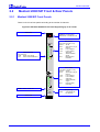
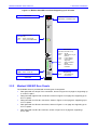
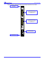


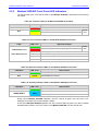

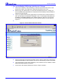
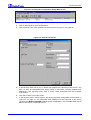
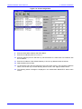


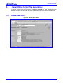
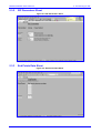
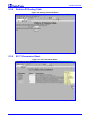


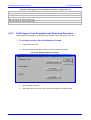
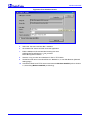

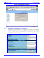
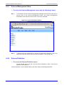
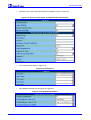
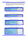
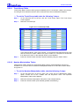
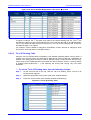
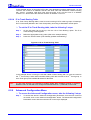
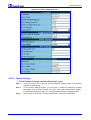
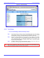
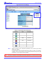
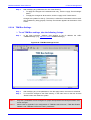
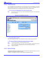
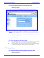
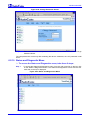
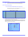
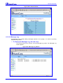
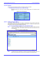
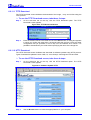
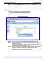


![LTRT-71403 MediaPack MGCP User Manual ver 4[1].](http://vs1.manualzilla.com/store/data/005760883_1-b98cf40cc1cd8cff0fa8bbf345d132db-150x150.png)