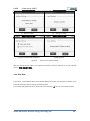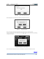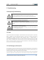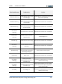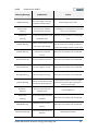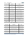
1
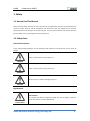
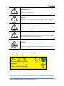
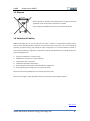
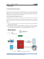
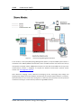
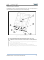
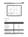
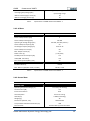
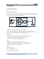
– Powervortex 306KTL Three-phase Grid-Tied Hybrid Inverter User Manual Version 1.1 GMDE Powervortex 306KTL Content Prelude ..................................................................................................................... 4 1. Safety.................................................................................................................... 5 1.1 How to Use This Manual.................................................................................................. 5 1.2 Safety Rules ..................................................................................................................... 5 1.3 Warning Notices Affixed to the Device ........................................................................... 6 1.4 Important Safety Information ......................................................................................... 6 1.5 Disposal ........................................................................................................................... 8 1.6 Exclusion of Liability ........................................................................................................ 8 2. Description ............................................................................................................ 9 2.1 General System Description ............................................................................................ 9 2.2 Description of the Device .............................................................................................. 11 2.3 Outside Dimension of the Device .................................................................................. 12 2.4 Technical Data ............................................................................................................... 12 2.4.1 DC Data ................................................................................................................... 12 2.4.2 AC Data ................................................................................................................... 13 2.4.3 General Data ........................................................................................................... 13 3. Installation .......................................................................................................... 15 3.1 Operation Sequence ...................................................................................................... 15 3.2 Unpacking ...................................................................................................................... 16 3.2.1 Packing List ............................................................................................................. 16 3.2.2 Unpacking the Device ............................................................................................. 16 3.2.3 Identifying the Inverter .......................................................................................... 17 3.3 Mounting ....................................................................................................................... 17 3.3.1 Assembly Site Requirements .................................................................................. 17 3.3.2 Mounting the Inverter ............................................................................................ 18 3.4 Electrical Connection ..................................................................................................... 20 3.4.1 Connectors.............................................................................................................. 20 3.4.2 DC Connection ........................................................................................................ 20 3.4.3 AC Connection ........................................................................................................ 21 Global Mainstream Dynamic Energy Technology Ltd. 2 GMDE Powervortex 306KTL 3.4.4 Communication Interface Port ............................................................................... 23 *3.4.5 Power Meter Installation...................................................................................... 24 4. LCD Display ......................................................................................................... 26 4.1 LCD Interface ................................................................................................................. 26 4.2 Menu Structure ............................................................................................................. 27 4.2.1 Main Menu ............................................................................................................. 27 4.2.2 Energy Menu Structure .......................................................................................... 29 4.2.3 Run Info Menu Display ........................................................................................... 30 4.2.4 Fault& Alarm Menu Display.................................................................................... 31 4.2.5 Setting Menu Display.............................................................................................. 32 4.2.6 “Inv Info.” Menu Display ........................................................................................ 32 4.3 Settings .......................................................................................................................... 32 4.3.1 Language Setting .................................................................................................... 34 4.3.2 Clock Setting ........................................................................................................... 34 4.3.3 Password Setting .................................................................................................... 35 4.3.4 Battery Setting ........................................................................................................ 36 4.3.5 Local Address .......................................................................................................... 37 4.3.6 Clear Data ............................................................................................................... 40 4.4 Fault, Warning and Historical Information Deleting ..................................................... 41 5. Troubleshooting .................................................................................................. 43 5.1Safety during Troubleshooting ....................................................................................... 43 5.2 Faults ............................................................................................................................. 43 5.3 Fault Messages and Actions List .................................................................................... 43 5.4 Fault Acknowledgement ................................................................................................ 47 5.5 Technical Service ........................................................................................................... 47 6. Maintenance ....................................................................................................... 48 6.1 Before Maintenance ...................................................................................................... 48 6.2 Visual Inspection............................................................................................................ 48 6.3 DC Switch Yearly Maintenance...................................................................................... 48 7. Contact ........................................................................................................... 49 Global Mainstream Dynamic Energy Technology Ltd. 3 GMDE Powervortex 306KTL Prelude Published by Global Mainstream Dynamic Energy Technology Ltd. (GMDE) Room 604-605, Tongpu Road No.1220, Putuo District, Shanghai, P.R.China. Tel: +86 21 60710809 Fax: +86 21 61730300 www.global-mde.com Legal Disclaimer All information in this documentation has been compiled and checked with most care. Despite of this, faults or deviations cannot be completely excluded. We assume no liability and are hereby acknowledged. The relevant up-to-date version can be obtained from www.global-mde.com Copyright The details of this documentation are the property of GMDE. Using and publicizing this documentation, even if only in parts require the written consent of GMDE. Read this user manual before you start Thank you for purchasing our products, this hybrid inverter is highly reliable and efficient due to its convenient design and excellent quality. This three phase device is IP65 rated for dusty or humid environments and is suitable for outdoor application. If you are reading the electronic version of the manual, please note that you can click the content to find information you want quickly. All the characters which contain underline are clickable. A phrase named ‘Back to Top’ at the bottom of each chapter can help you back to the first page rapidly. Before using this device, please ensure that you have read this manual including installation and safety operation carefully. If you have any difficulties during installation or operation, please refer to this manual or send email to [email protected],we will help to solve your problems as soon as possible. Back to Top Global Mainstream Dynamic Energy Technology Ltd. 4 GMDE Powervortex 306KTL 1. Safety 1.1 How to Use This Manual Please read the safety instructions in this manual first. Throughout the manual it is assumed that the reader is familiar with AC and DC installations and knows the rules and regulations for electrical equipment and for connecting it to the utility AC grid. It is especially important to be familiar with the general safety rules for working with electrical equipment. 1.2 Safety Rules General introduction These safety-related guidelines use the following ANSI notations to describe the various levels of danger: Death or severe personal injury will occur. DANGER Death or severe personal injury may occur. WARNING Personal injury or material damage may occur. CAUTION Explanations Electric Shock! Do not open the device! Dangerous voltage may still be applied inside the device even after it has been switched off. Electric Shock! Global Mainstream Dynamic Energy Technology Ltd. 5 GMDE Powervortex 306KTL High leakage current! Make absolutely sure you establish connection to ground before connecting the device to the supply circuit! WARNING Health risk! Health risk for persons with cardiac pacemakers, metallic implants, or hearing aids in the immediate vicinity of electrical equipment! WARNING Risk of improper handling! Personal injury by crushing, shearing, cutting, or striking. CAUTION Cancellation of the operating license! If the GMDE inverter is operated with a wrong country code, the electric supply company may cancel the operating license. CAUTION Hot Surface! Surfaces of the housing can be hot! Risk of injury! Risk of burns. Hot Surface! The housing top and the heat sinks may have a surface temperature of 70°C 1.3 Warning Notices Affixed to the Device 1.4 Important Safety Information The following operating and maintenance instructions must be read before installing, operating or Global Mainstream Dynamic Energy Technology Ltd. 6 GMDE Powervortex 306KTL maintaining the inverter. Before installation: Check for damage to inverter and package. If you are in doubt, please contact us or the distributor before installing the inverter. Before connecting the solar modules to the inverter, check the voltages and make sure they are within the limits of the GMDE inverter specifications. Failure to observe these specifications could void your warranty. Installation: Only trained and qualified personnel familiar with local electrical codes may work with the electrical installations. For optimum safety, please follow the steps described in this manual. Disconnecting the inverter: Please refer to “Disconnecting for maintenance” in section6.1 Before Maintenance. Note that wait at least 15 minutes before proceeding, after disconnecting the hybrid inverter from AC grid, PV panels and battery packs. Operating the inverter: Do not commission the device until the overall system complies with the application-specific national rules and safety regulations. The ambient conditions given in the product documentation must be observed. The machine or installation manufacturer is responsible for compliance with the limit values as prescribed in the national regulations. Only persons who are trained and qualified for the use and operation of this device may work on the device. Maintenance and modification: Only authorized personnel are allowed to repair or modify the inverter. To ensure optimum safety for user and environment, only the original spare parts available from your supplier should be used. Functional safety parameters: Unauthorized changes of functional safety parameters may cause injury or accidents to people or inverter. Additionally it will lead to the cancellation of all inverter operating approval certificates. Global Mainstream Dynamic Energy Technology Ltd. 7 GMDE Powervortex 306KTL 1.5 Disposal Please dispose the package and replaced parts according to the rules applicable in the country where the device is installed. Do not dispose the GMDE inverter with normal domestic waste. 1.6 Exclusion of Liability GMDE Technology Ltd. will not be liable for any direct, indirect or consequential damages, losses, costs or losses including without restriction any economic losses of any kind, any loss or damage to property, any personal injury, any damage or injury arising from or as a result of misuse or abuse, or the incorrect installation, integration or operation of the product. We disclaim any liability for direct or indirect damages due to: 1. Improper installation or commissioning, 2. Modifications, alterations or repair attempts, 3. Inappropriate use or operation, 4. Insufficient ventilation of the device, 5. Non-compliance with relevant safety standards or regulations, 6. Flood, lightning, overvoltage, storm, fire (acts of nature). We do not assume any liability for an incorrectly set country code. We reserve the right to make alterations that will improve the functioning of the device. Back to Top Global Mainstream Dynamic Energy Technology Ltd. 8 GMDE Powervortex 306KTL 2. Description 2.1 General System Description GMDE Powervortex series hybrid inverters are designed for customers to build new PV energy storage system as it is shown in below Figure 1 and Figure 2. GMDE all-in-one designed hybrid inverter integrates both solar inverter and battery inverter. The energy management solutions of the energy storage systems are described as solution 1 and solution 2. Solution1: Integrated Energy Management Solution Through RS485 cable, the hybrid inverter communicates with the power meter that is installed between the AC grid and the customer load. With the power-related information sent from the power meter, the hybrid inverter can automatically decide how to charge or discharge the connected battery packs. Note that: (1) In this solution, lead-acid batteries can be integrated into the energy storage system without BMS (Battery Management System). (2) If lithium batteries are adopted, an independent BMS is compulsory to maintain battery’s lifetime. (3) The power meter used in this application must be confirmed by GMDE first since the integration of communication protocol between power meter and GMDE hybrid inverter is required. Figure 1 Integrated Energy Management Solutions Global Mainstream Dynamic Energy Technology Ltd. 9 GMDE Powervortex 306KTL Solution2: External Energy Management Solution Figure 2 External Energy Management Solutions In this solution, a third party EMS (Energy Management System) is required. GMDE hybrid inverter is connected to this EMS by RS485 communication cable. The EMS monitors and controls the start-up and operation of hybrid inverter. GMDE hybrid inverter can work with all the EMS units as long as the communication protocol is integrated. To request the detailed communication protocol, please contact us at [email protected]. Note: Maximum Charging current, Maximum Discharging current, Discharging Stop Voltage and Charging Stop Voltage should be set before commissioning to maintain battery’s lifetime. In solution1, these parameters are set in LCD screen see Figure 3. In solution2, these parameters are set by external commands according to communication protocol through RS485 interface. Global Mainstream Dynamic Energy Technology Ltd. 10 GMDE Powervortex 306KTL 2.2 Description of the Device The GMDE Hybrid inverter is a three-phase transformerless inverter, which could help customers to reduce their electricity expense by optimizing use of PV and battery energy. Figure 4 ① ② GMDE Powervortex306KTL Heat is dissipated by the heatsink and fan equipped at the bottom of this device. One AC output connector, which connect to AC grid and local load. (Rated conductor size: Ø 2 6 mm ). ③ Two pairs of PV-input terminals, each input pair consists of positive and negative terminals. ④ One pair of battery input terminals. ⑤ Integrated DC switch to switch on/off the PV and battery. ⑥ The GMDE hybrid inverter provides multiple communication choice: RS485/USB. ⑦ 320x240 pixels display screen, on which the operation related information can be displayed. Global Mainstream Dynamic Energy Technology Ltd. 11 GMDE Powervortex 306KTL 2.3 Outside Dimension of the Device Figure 5 Outside dimension of GMDE Powervortex306KTL 2.4 Technical Data 2.4.1 DC Data MODEL LIST Powervortex 306KTL HI PV INPUT (DC) Maximum PV Power [kW] 6.3 VMAX 800 PV [Vdc] Nominal DC voltage [Vdc] 640 MPP Voltage Range [Vdc] 350-700 Max. Input Current [A] 18 Input Voltage Range [Vdc] 200~800 Start PV Voltage [Vdc] 300 Stop PV Voltage [Vdc] 200 MPP Trackers 1 BATTERY INPUT(DC) Maximum DC Power [kW] 6 Full Power Operating DC Voltage Range [Vdc] 300-800 Operating DC Voltage Range [Vdc] 200-800 Charging Upper Limit Voltage [Vdc] Being adjustable according to actual battery Global Mainstream Dynamic Energy Technology Ltd. 12 GMDE Powervortex 306KTL packs configuration, as long as not exceed the Discharging Stop Voltage [Vdc] input voltage range. Maximum Discharging Current [A] 20 Maximum Charging Current [A] 20 Table 1 Specifications of GMDE Powervortex306KTL -1 2.4.2 AC Data MODEL LIST Powervortex 306KTL HI OUTPUT (AC) Nominal Output Power [kW] 6 Nominal Output Voltage [Vac] 3N~400 Operating AC Voltage Range [Vac] 324-436, 437-460 (<10min.) Nominal Output Frequency [Hz] 50 AC Voltage Frequency Range [Hz] 47.55-51.45 Nominal Output Current [A] 8.6 Max. Output Current [A] 9.5 Power Factor [λ] [-0.95, 0.95] Standby Power Consumption [W] < 15 THDI (100% Full Power) < 3% DC Current Injection (Max.) [mA] 50 EFFICIENCY PV MPPT Efficiency > 99.5% Max. Efficiency (PV/BAT->Load, PV->BAT) Table 2 ≥ 96.5%, ≥ 97% Specifications of GMDE Powervortex306KTL -2 2.4.3 General Data MODEL LIST Powervortex 306KTL HI GENERAL DATA Operating Temperature Range [◦C] -25 to 60 (> 45 derating) Noise Emission [dB] < 55 Enclosure Protection IP65 Heat dissipation Forced air cooling Altitude [m] < 2000 (no derating) Weight [kg] 48 Dimensions [W*H*D, mm] 540*670*290 Array Insulation Resistance Detection [Ω] DC Disconnect > 1M Standard VDE approved DC switch Global Mainstream Dynamic Energy Technology Ltd. 13 GMDE Powervortex 306KTL Ground Fault Protection Internal GFCI and isolation detection function, following Installation Mode VDE0126-1-1 Wall-mounted Humidity < 95% RH Communication Interface USB/RS485 Hazard Substance Restriction Lead free, complied with RoHS GP2 Display Graphic: 320 × 240; function key × 5 Table 3 Specifications of GMDE Powervortex 306KTL-3 Back to Top Global Mainstream Dynamic Energy Technology Ltd. 14 GMDE Powervortex 306KTL 3. Installation 3.1 Operation Sequence Important Note before Operation In order to ensure the smooth operation of hybrid inverter and reduce the negative impact on local load in case of inverter maintenance, we strongly recommend the users to connect the hybrid inverter into the existing electrical system as following figure shows: PV MPPT PV Array DC Switch Grid DC AC Breaker DC + — Hybrid Inverter DC DC Breaker D1 To Grid K1 AC DC BAT DC Battery Pack BAT Bi-CONVERTER Figure 6 Customer Load Recommended system configuration One AC breakers, K1, should be installed to connect to the AC grid. An external DC breaker D1 (or fuse) is installed between battery packs and hybrid inverter. (Note a DC switch is already integrated into the hybrid inverter, this DC switch cannot be used to directly switch off the inverter when the inverter is running with power.) Installation: 1. Please read the user manual carefully and pay special attention to the safety rules. 2. Unpack and install the inverter according to section 3.2 and section 3.3. 3. Connect PV and battery input according to section 3.4.2. 4. Connect AC grid and customer load according to section 3.4.3. Setting: 5. Connect the PV and battery input by turning the DC switch on. 6. Set language, clock, password via LCD displayer, please refers to section 4.2.1~4.2.3. 7. Set battery packs information via LCD displayer, please refer to section 4.3.4. 8. Shutdown DC switch (for saving the parameters). Starting: 9. Turn on AC Breaker K1. 10. Turn on DC Breaker D1. 11. Turn on DC switch of hybrid inverter. The inverter is now ready for operation. Global Mainstream Dynamic Energy Technology Ltd. 15 GMDE Powervortex 306KTL Disconnecting for maintenance: 1. Turn off AC Breaker K1. 2. Turn off DC Breaker D1. 3. Turn off DC switch of hybrid inverter. 4. Wait at least 15 minutes before repairing or maintenance. Now the hybrid inverter can be removed safely for maintenance. 5. Disconnect those cables with the inverter and then move the inverter to a suitable place for later maintenance. 3.2 Unpacking 3.2.1 Packing List The following items are included in the GMDE hybrid inverter package: 1. GMDE Powervortex 306KTLx 1 2. User Manual x 1 3. Certificate of Approval x 1 4. Cable Gland (for AC grid connection) x 1 5. Aviation Plug Male Connector (for AC load connection) x1 6. Expansion Bolts (M8*12mm) x 4, Flat Pad x 4, Spring Washers x 4 and Screw Nut x 4 7. Wall Bracket for the inverter x 1 3.2.2 Unpacking the Device The inverters are loaded at their heads and packed face up to facilitate transportation. You will therefore see the up side of the device after having opened the package. Take the device at the two holding grips that are visible on the side and remove it from the package. Figure 7 Front panel of GMDE Powervortex 306KTL Global Mainstream Dynamic Energy Technology Ltd. 16 GMDE Powervortex 306KTL 3.2.3 Identifying the Inverter Figure 8 Label of GMDE Powervortex 306KTL 3.3 Mounting 3.3.1 Assembly Site Requirements 1. The assembly site must be shaded so that the inverter can achieve the highest energy production and the longest life. 2. The installation wall must be vertical and can carry the weight of the inverter. 3. For the assembly, it is necessary to choose a solid wall or metal construction, which comply the fire protection class F30 and the load capacity of 60kg per unit. Relevant provisions of construction Global Mainstream Dynamic Energy Technology Ltd. 17 GMDE Powervortex 306KTL regulations must be observed! 4. Mount the device at an appropriate distance from combustible materials. 5. We recommend that you mount the device at eye level to ensure optimum user comfort. 6. Owing to its protection type (IP65), the device can also be mounted in outside areas. Figure 9 Installation patterns 3.3.2 Mounting the Inverter There are only two steps to mount the inverter. The first step is fixing the wall bracket and the second step is mounting the inverter. All the steps are shown below by the form of illustration. The wall bracket can be fixed to the wall by four expansion bolts (M8*12mm: thread diameter is 8mm, nominal diameter is 12mm). Select the appropriate screw types and dimensions for the wall material is very important. Inverter weight and dimensions are listed as follows: Description Powervortex 306KTL Dimension Weight 3-phase Transformerless Grid-tied Hybrid Inverter (maximum PV power: 6kW; maximum battery power: 6kW; Maximum output power: 6kW) 670mm x 540mm x 290mm 48 kg Table 3 Information of GMDE Powervortex 306KTL Global Mainstream Dynamic Energy Technology Ltd. 18 GMDE Powervortex 306KTL Mount the wall bracket by the following procedure: 1. Mark the position on the wall of the bracket: Hold the wall bracket to the wall, keep the sides vertical, and mark screw position. 2. Remove the wall bracket, and then drill holes. 3. Hold the wall bracket in position and insert all screws. 4. Fix the wall bracket by turning the screws. The diagram of mounting the wall bracket is showed below: Figure 10 Inverter wall bracket Hang the inverter on the wall bracket by the following steps: 1. Move the inverter in the suitable horizon direction. 2. Make the hook on wall bracket inserting in the slot behind inverter. 3. Keep the inverter down slowly to ensure the inverter hang on the hook. 4. Check the inverter securely fixed on the wall bracket. The inverter wall mounting procedure is shown below: Global Mainstream Dynamic Energy Technology Ltd. 19 GMDE Powervortex 306KTL Figure 11 Inverter wall mounting procedure 3.4 Electrical Connection 3.4.1 Connectors The GMDE inverter is provided with the following connectors, as seen below from left to right: 1. Two pairs of PV-input terminals. 2. Integrated DC switch. 3. One pair of battery input terminal. 4. Communication-interface includes RS 485 A/B, USB. 5. One AC-output connector (L1/L2/L3/N/G), which can connect to power grid and customer load respectively, as the Figure 11 shows. Figure 12 Device connectors 3.4.2 DC Connection DC Connection procedure is shown in the following steps: 1. Please double check to ensure that the DC switch is turned off before your connection! Global Mainstream Dynamic Energy Technology Ltd. 20 GMDE 2. Powervortex 306KTL Insert PV and battery cables into the PV and battery terminals. Figure 13 PV connection – PV input terminals 3.4.3 AC Connection There is one AC output terminal as shown in the following figure: Figure 14 1. AC output terminals The “AC GRID” AC output terminal is equipped with aviation plug. Figure 15 “AC GRID” AC output terminal-aviation plug The female connector of the aviation plug has already been installed at the interface of the hybrid Global Mainstream Dynamic Energy Technology Ltd. 21 GMDE Powervortex 306KTL inverter. The male connector could be found in the packing box. Please find the recommended AC output cable size: Do not use cables of which losses exceed 1%. L1 (Line 1), L2 (Line 2) L3 (Line 3), N (Neutral), G (PE): Ø 6mm 2 The detailed installation procedures of this AC output terminal is explained as following figures: Step 1Insert the cables into male connector and tighten in clockwise Step 3 Insert male connector into female connector Figure 16 Step 2 Tighten the covers of the male connector Step 4 Tighten the male connector clockwise AC connection - “AC GRID” connection Global Mainstream Dynamic Energy Technology Ltd. 22 GMDE Powervortex 306KTL 3.4.4 Communication Interface Port Powervortex 306KTL inverter provides two types of communication ports: RS485 and USB. Please refer to the following procedures of the communication connection. Figure 17 Communication connection–communication interface RS485 Configuration: GMDE inverter uses RJ45 jacks as the RS485 communication port. The RJ45 plug pin allocation is illustrated by Figure 18 RJ45 plug pins allocation. Figure 18 RJ45 plug pins allocation Global Mainstream Dynamic Energy Technology Ltd. 23 GMDE Powervortex 306KTL Pin No. Illustration 1 - 2 - 3 Data+ 4 GND 5 GND 6 Data- 7 5V 8 5V Table 4 RJ45 plug pins illustration B-USB port: Figure 19 Insert the RS485cables *Note: The B-USB port will only be used for software update. *3.4.5 Power Meter Installation (This section is only for the Integrated Energy Management Solution in section 2.1 General System Description) The wire connection of power meter is shown as below: 1) Connect the AC grid to the power meter on the “↑” marked side. Connect the load on the other side. Pay attention to the Neutral line connection. 2) Connect the RS485 cable to the power meter according to section 3.4.4 Communication Interface Port: connect the terminal “7” with the pin 3 Data+; connect the terminal “8” with the pin 6 Data-(Table 4 RJ45 plug ). Global Mainstream Dynamic Energy Technology Ltd. 24 GMDE Powervortex 306KTL From AC GRID Wire connection Connecting direction RS485 connection-1 RS485 connection-2 Figure 20 Wire connection of power meter Back to Top Global Mainstream Dynamic Energy Technology Ltd. 25 GMDE Powervortex 306KTL 4. LCD Display 4.1 LCD Interface All information related to the inverter can be obtained from the LCD display. There are 5 keys for navigating in the LCD display menu. The functions of the navigating keys and indication lightings around the LCD screen are displayed in the following: Figure 21 LCD display Item Symbol Meaning ① ▲ Up ② ▼ Down Move forward to down item or next page Enter/ Escape Enter into or escape from the current page ⑤ ▼ ④ Move back to the upper item or previous page Left Move toward the left item or previous page ▼ ③ Illustration Right Move toward the right item or next page Table 5 Function introduction Global Mainstream Dynamic Energy Technology Ltd. 26 GMDE Powervortex 306KTL 4.2 Menu Structure 4.2.1 Main Menu The energy management system has two solutions, refer to 2.1 General System Description. The main menus of LCD are shown below, which are also the default window after the LCD is lighting. In solution 1: Figure 22 Main menu of LCD for solution 1 Item Description ① Operating status of the inverter ② Voltage/Current of PV group1 ③ Voltage/Current of PV group2 ④ Energy production of PV modules ⑤ Energy production of the hybrid inverter ⑥ Output power of AC grid ⑦ Output power of hybrid inverter ⑧ Power consumption of customer load ⑨ Time Table 6 Main menu illustration Global Mainstream Dynamic Energy Technology Ltd. 27 GMDE Powervortex 306KTL In solution 2: Figure 23 Item Main menu of LCD for solution 2 Description ① Operating status of the inverter ② Voltage/Current of PV group1 ③ Voltage/Current of PV group2 ④ Energy production of PV modules ⑤ Energy production of the hybrid inverter ⑥ Time ⑦ Three phase output Voltage/Current of hybrid inverter Table 7 Main menu illustration In solution 1, at the bottom of the main menu, by pressing the navigating keys, the different energy information (both of DC and AC sides) could be displayed as the following figure shows. Global Mainstream Dynamic Energy Technology Ltd. 28 GMDE Powervortex 306KTL (a) DC side energy information Figure 24 (b) AC side energy information Energy information display The corresponding descriptions of the abbreviations: Epv: Total energy generated by solar panels. Ebat-c: Total charging energy to battery packs. Ebat-d: Total discharging energy from battery packs. Einv: Total energy delivered by the inverter. Egrid-d: Total energy injected to the power grid. Egrid-c: Total energy provided by power grid to the customers. Eload: Total energy consumption of local customers. Press “ ” key on the Figure 22main menu and then enter into the following selection menu on which more detailed information could be found. Figure 25 Main selection menu 4.2.2 Energy Menu Structure In the “Energy” submenu, all the historical data information can be found. By pressing “ Figure 25 main selection menu, the screen enters into “Energy” menu. Global Mainstream Dynamic Energy Technology Ltd. ” on the 29 GMDE Powervortex 306KTL In the “Energy” menu window, all the daily, weekly and annual historical data can be displayed as shown in Figure 26. Figure 26 The “Energy” menu structure 4.2.3 Run Info Menu Display The current operating status information could be found in the “Run Info” menu. By pressing “ ” on the Figure 25 main selection menu, the screen enters into “Run Info” menu as shown in Figure 27. Global Mainstream Dynamic Energy Technology Ltd. 30 GMDE Powervortex 306KTL Figure 27 “Run Info” menu By pressing“ ”, “ ” keys on the “Run Info” menu window, the current run information could be switched between DC side (PV and battery) and AC side (grid and load). (a) Run information on DC side Figure 28 (b) Run information on AC side “Run Info” menu structure *Note: Pbat-c, current charging power; Pbat-d, current discharging power; 4.2.4 Fault& Alarm Menu Display The “fault and alarm” information of the inverter operation is included in this menu. Detailed description of the faults and warnings information can be found at section 5.3. Global Mainstream Dynamic Energy Technology Ltd. 31 GMDE Powervortex 306KTL Figure 29 “Fault& Alarm” menu structure 4.2.5 Setting Menu Display Please refer to section 4.3 for the detailed setting items. 4.2.6 “Inv Info.” Menu Display The manufacture and software version information of the inverter is stored in this menu. Figure 30 Menu structure of inverter information 4.3 Settings When turning on the inverter for the first time, the customer needs to finish the following initializing settings: language setting, regulation setting, clock setting, password setting and clear data. Press “▼”key into the main selection menu from main menu. Global Mainstream Dynamic Energy Technology Ltd. 32 GMDE Powervortex 306KTL Figure 31 Main selection menu While selecting “setting” on the main selection menu and pressing “ a message boxwill pop up(the default password is 6666). Figure 32 ”to enter into the setting menu, Password of change settings Press “OK” button to finish the password input; Press “Back” button to return. By pressing “Setting” on the main selection menu, the screen enters into the “Setting” menu. The default item is “Lan. Setting” (Language setting), as shown in Figure 33. Figure 33 Main setting display Global Mainstream Dynamic Energy Technology Ltd. 33 GMDE Powervortex 306KTL 4.3.1 Language Setting Press “ ” into the default “Language” setting page. Use the navigating keys to select the language. The default language is “English”. Figure 34 Language setting Press “OK” button to finish the password input; Press “Back” button to return. 4.3.2 Clock Setting While pressing “ ”key on the main setting window, the screen enters into “Clk. setting”. Figure 35 Selecting clock setting In “Clk. Setting” window, use the navigating keys to set the local time. Global Mainstream Dynamic Energy Technology Ltd. 34 GMDE Powervortex 306KTL Figure 36 Clock setting Press “OK” button to finish the password input; Press “Back” button to return. 4.3.3 Password Setting While pressing “ ” key on the main setting window, the screen enters into “Pas. Setting”. The password can be modified as shown in Figure 37. Step 1 Press “ ” into password setting window Step 2 Use navigating keys to input the current password (the initial password is 6666) Step 3 Use navigating keys to input the new Step 4 Input the new password again for password confirmation Figure 37 Password setting Global Mainstream Dynamic Energy Technology Ltd. 35 GMDE Powervortex 306KTL *Note: 1. In the above procedures, press “OK” button to go to the next step; Press “Back” button to return. 2. Please remember the new password if the customer changes it. Once forgetting the new password, please contact the service center of GMDE who will help you to resume the initial password. 4.3.4 Battery Setting While pressing “ ” key on the main setting window, the screen enters into “Bat. Setting”. Figure 38 Selecting “Battery” setting The Maximum Discharging current, Maximum Charging current, Discharging Stop Voltage and Charging Stop Voltage can be set as shown in the following figure. (a) Parameter input (b) Waiting for Setting Global Mainstream Dynamic Energy Technology Ltd. 36 GMDE Powervortex 306KTL (c) Setting not successful (d) Setting successfully (e) Not supported at solution 2 Figure 39 (f) Not supported during the inverter running Battery setting After setting the parameters of the battery packs, shut down the DC switch and follow the setting & starting procedures in section 3.1. 4.3.5 Local Address Note: In solution 1 with integrated EMS, the local address will not be used since the inverter does not communicate with any external system. In solution 2 with external EMS, the inverter is controlled by external commands through RS485. Hence the local address is required to set up the communication channels between inverters and energy management system. In this menu, user could set the local address by the following procedures. Global Mainstream Dynamic Energy Technology Ltd. 37 GMDE Powervortex 306KTL Figure 40 Local Address setting Note: The default setting is ‘Fixed Add. Mode’ with local address 255. Before communicating with the external EMS, the local address should be set as fixed address( between 1 to 254) or dynamic address. Figure 41 Default Addr. Setting window (a) Set fixed local address(b)Select OK to confirm Global Mainstream Dynamic Energy Technology Ltd. 38 GMDE Powervortex 306KTL (c) Wait for setting (d) Setting successful (e) Fixed address recognition Figure 42 (f) Setting failed Fixed local address setting (a) Select Dynamic Add. Mode Global Mainstream Dynamic Energy Technology Ltd. (b) Select OK to confirm 39 GMDE Powervortex 306KTL (c) Wait for setting (d) (e) Dynamic Add. Mode recognition Figure 43 Setting successful (f) Setting failed Dynamic local address setting After the setting of local address, the address information could be observed in Inv Info. Window show in 错误!未找到引用源。 4.3.6 Clear Data In this menu, all the historical data can be deleted. Please ensure that you really want to delete all the historical information before starting the following steps. On the main setting window, select “Clear Data” item and press “ ” into the “Clear Data” window. Global Mainstream Dynamic Energy Technology Ltd. 40 GMDE Powervortex 306KTL Figure 44 Selecting “Clear Data” A confirmation message box as Figure 45will pop up. Figure 45 Message box of "Clear Data" Press “OK” button to delete all the historical data; Press “Back” button to cancel. 4.4 Fault, Warning and Historical Information Deleting In section 4.3.5 , all the historical data including fault and warning information can be deleted. Besides, we also provide a way to delete the specific information by the combination use of the navigating keys. 1. On the “energy” menu window, by pressing“ ” + “ ” keys at the same time, the following message box will pop up. Global Mainstream Dynamic Energy Technology Ltd. 41 GMDE Powervortex 306KTL Figure 463 Input of data deleting password After inputting the correct password, the following message box will pop up. Figure 47 Energy data deleting Press “Yes” button to delete the historical data in this page, press “No” button to cancel. 2. On the “Fault& Alarm” menu window, by pressing“ ” + “ ” keys at the same time, the following message box will appear: Figure 48“Fault& Alarm” data clearing Press “Yes” button to delete all the historical “Fault& Alarm” data; Press “No” button to cancel. Back to Top Global Mainstream Dynamic Energy Technology Ltd. 42 GMDE Powervortex 306KTL 5. Troubleshooting 5.1Safety during Troubleshooting High electric voltage! Risk of death or personal injury by electric shock! Never work with live wires! It is prior to all connection and maintenance work. Make sure that the AC and DC wires are not charged. The connection area should only be opened by a licensed electrician. Warning! Danger from residual voltage out of capacitors. You must wait until the capacitors have fully discharged. Discharge takes around15 minutes. Caution! Danger from inadequate grounding. An inadequate grounding conductor connection can cause serious injuries to persons and damage to properties. 5.2 Faults A fault can be divided into two catalogues: a permanent failure and a temporary failure. A ‘permanent failure’ is defined by a fault having been present for more than 15 minutes and cannot be acknowledged by inverter’s auto-restart. Unlike permanent failure, a “transient failure" is automatically acknowledged by the inverter. The inverter attempts to restart once the error no longer exists. The fault is indicated on the control panel by the red "Alarm" LED emitting steady light. Most failures are transient; therefore the system should be monitored for a while before contacting the service as the transient failure may disappear itself. 5.3 Fault Messages and Actions List Fault messages are stored in the fault memory even in the status of power failure. The fault data can be retrieved to display on the screen. The latest 100 fault logs are recorded in the fault memory. The latest fault is kept at memory location S0 while the earliest at S100. The transient failure is shown as “Warning” while the permanent failure as “Fault”. Check ‘Warnings and actions’ table when a transient failure occur sand check the ‘Faults and actions’ table when a Global Mainstream Dynamic Energy Technology Ltd. 43 GMDE Powervortex 306KTL permanent failure occurs. Warning Message Offset-Iac-Warning ENS-Mess-Warning ENS-GFCI-Warning Curr-SensorWarning Explanation Action The DC injection of grid current Acknowledge error. Contact the service if the is out of range. Different value between master and slave CPU. Different value between master and slave for GFCI. The current sensor is abnormal. Inverter-Curr- Inverter current is over the Warning tolerable value. GFCI-Warning Residual current is out of range. GFCI-Device- The GFCI detection circuit is Warning abnormal. error occurs repeatedly. Wait until the controller has re-stabilized. Wait until the controller has re-stabilized. Wait until the controller has re-stabilized. Acknowledge error. Wait until the controller has re-stabilized. Wait until the controller has re-stabilized. Isolation resistance of PV-plant Zpv-PE-Warning out of tolerable range before Check insulation of the system. connecting to the grid. Rly-Warning Vac-MasterWarning Relay is Fail. Master-grid voltage measurement-value out of Wait until the controller has re-stabilized. Re-measure line voltage Service if line voltage is within normal range. tolerable range. Fac-Master- The master-frequency is out of Warning tolerable range. No-Utility Grid voltage =0. Check system frequency and line voltage. Contact the Service if system frequency is within normal range. Re-measure line voltage Service if line voltage Global Mainstream Dynamic Energy Technology Ltd. is within normal range. 44 GMDE Powervortex 306KTL Warning Message VpvMax-Warning Explanation Action PV input voltage is over the Check voltage of solar cells. tolerable maximum value. Master-Slave- Communication between Acknowledge error. Contact the service if the Warning microcontrollers is failing. error occurs repeatedly. Temperature- The internal temperature is out Allow the unit to cool down. Acknowledge Warning of tolerable value. error. ENS-Vac-Warning Different value between master and slave for grid voltage. Possibly caused by switching actions on the net. Re-measure line voltage. Contact the Service if line voltage is within normal range. Different value between master ENS-DCI-Warning and slave for output DC Wait until the controller has re-stabilized. current. Bus-Start-Warning DC bus soft start is over time. Wait until the controller has re-stabilized. Bus-Low-Warning DC bus voltage is too low. Wait until the controller has re-stabilized. Bus-High-Warning DC bus voltage is too high. Wait until the controller has re-stabilized. ENS-Fac-Warning Different value between master and slave for grid frequency. Boost-Curr- Boost current is over the Warning tolerable value. PV-Connect- PV connection type cannot be Warning identified. EEPROM-Warning Boost-Start-Warning EEPROM cannot be read or written. Check system frequency and line voltage. Contact the Service if system frequency is within normal range. Acknowledge error. Wait until the controller has re-stabilized. Wait until the controller has re-stabilized. Time limit exceeded of DC bus soft-start. Global Mainstream Dynamic Energy Technology Ltd. Restart Hybrid inverter. 45 GMDE Powervortex 306KTL Warning Message Explanation Action PV DC power over maximum Reduce the power of PV array, and then limit restart Hybrid inverter. Fan-LockWarning Fan lock Check fan. Over-voltage of battery The battery voltage is higher Acknowledge error. Contact the service if the banks than the upper limit. error occurs repeatedly. Low battery voltage The battery voltage is too low. Over-current of battery The battery current is higher Check battery packs. Contact the service if banks than the upper limit. the error occurs repeatedly. Low battery energy The battery energy is too low. PV Over Power External Comm. Warning Bat. Parameters warning Please set parameter of the Battery Check battery packs. Contact the service if the error occurs repeatedly. Check battery packs. Contact the service if the error occurs repeatedly. External communication Check RS485 communication cable warning. connection Battery parameter is Zero warning. Table 8 Set battery parameters before running Warnings and actions Fault messages Explanation Action GFCI-Device-Failure The GFCI detection circuit is abnormal. Contact the Service Curr-Sensor Fault The Current sensor is abnormal. Contact the Service Inverter-Curr-Fail Inverter current is over the tolerable value. Contact the Service PV-Connect-Fail PV connection type cannot be identified. Contact the Service Global Mainstream Dynamic Energy Technology Ltd. 46 GMDE Powervortex 306KTL Fault messages Explanation Action Bus-Low-Fail DC bus voltage is too low. Contact the Service Bus-High-Fail DC bus voltage is too high. Contact the Service ENS-Mess-Fail Different value between master and slave. Contact the Service Master and slave firmware version is M-S Version Fail unmatched. Contact the Service Offset-Iac-Fail The DC injection of grid current is out of range. Contact the Service Rly-Fail Relay is Fail. Contact the Service Table 9 Fault sand actions 5.4 Fault Acknowledgement After shutdown due to a fault, the device remains locked against reactivation until the fault is acknowledged. The fault can only be acknowledged after the cause of the fault has been eliminated. To acknowledge the fault messages, press the ESC key or turn the GMDE inverter off with the DC switch. Wait for a while and turn the device on again. 5.5 Technical Service GMDE Room 604-605, Tongpu Road No.1220, Putuo District, Shanghai 200333, P.R. China TEL: +86 21 60710809-818 FAX: +86 21 61730300 E-mail: [email protected] WEB: www.global-mde.com SKYPE: GMDE Service Back to Top Global Mainstream Dynamic Energy Technology Ltd. 47 GMDE Powervortex 306KTL 6. Maintenance 6.1 Before Maintenance Please refer to “Disconnecting for maintenance” in section3.1 Operation Sequence. 6.2 Visual Inspection You should conduct visual inspection at least once a year. The visual inspection includes checking the machine cover, interface and screen. 6.3 DC Switch Yearly Maintenance To ensure the functionality of the DC switches, all switches should be turned on and off about ten times once a year to clean the contacts. Back to top Global Mainstream Dynamic Energy Technology Ltd. 48 GMDE Powervortex 306KTL 7. Contact If you have any questions about our product, please contact us: GMDE Room 604-605, Tongpu Road No.1220, Putuo District, Shanghai 200333, P.R. China TEL: +86 21 60710809-818 FAX: +86 21 61730300 E-mail: [email protected] WEB: www.global-mde.com SKYPE: GMDE Service Back to Top Global Mainstream Dynamic Energy Technology Ltd. 49