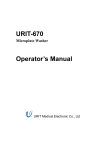
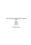
1
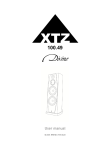
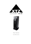
MF/HF/VHF DSC Marine Radio Test System (MRTS-7)
Technical description and user manual
MF/HF/VHF DSC Marine Radio Test System
MRTS - 7
Technical description and user manual
MF/HF/VHF DSC Marine Radio Test System (MRTS-7)
Technical description and user manual
Changes indication page
Date
Signature
Internal
accompanying
document reference
number
canceled
New one
Changed or
updated
Item number
Changes
Page number
Document number
Changes indication page
page 1
22.01.2007
MF/HF/VHF DSC Marine Radio Test System (MRTS-7)
Technical description and user manual
Actual content pages
Item
Page
Date
Page
Date
1
22.01.07
Item 6
Operation
guideline
16
12.10.07
Actual content
pages
2
22.01.07
Item 7
Tester’s
calibration
17
22.01.07
Contents
3
22.01.07
Item 1
Purpose
4
14.01.08
Item 8
Maintenance
guideline
18
22.01.07
Item 2
Main features and
characteristics
6
Item 9
Storage rules
19
22.01.07
12.10.07
20
14.01.08
8
22.01.07
Appendix 1.
Controller
software update
manual
Item 3
Complete set
Item 4
Operation
9
22.01.07
Item 5
Preparation for
operation and
operation
procedures
10
29.10.07
Changes
indication page
Actual content pages
Item
Page 2
22.01.2007
MF/HF/VHF DSC Marine Radio Test System (MRTS-7)
Technical description and user manual
CONTENTS
Item name
Item
Page
Changes indication page
1
Actual content pages
2
Contents
3
Purpose
1
4-5
Main features and characteristics
2
6-7
Complete set
3
8
Operation
4
9
Preparation for operation and operation procedures
5
10-15
Operation guideline
6
16-16-16
Tester’s calibration
7
17
Maintenance guideline
8
18
Storage rules
9
19
Appendix 1
20
Controller software update manual
Contents
page 3
22.01.2007
MF/HF/VHF DSC Marine Radio Test System (MRTS-7)
Technical description and user manual
1. PURPOSE
The MF/HF/VHF DSC Marine Radio Test System MRTS-7 (further tester) is intended to
carry out the efficiency, maintenance and servicing tests of the following equipment
(under IMO A.948(23) resolution):
●
VHF receiver-transmitters:
- efficiency tests on 6, 13 and 16 channels;
- test of frequency and output power;
●
VHF receiver-transmitters with DSC:
- test confirming the correctness of the MMSI code programmed in equipment
without any broadcast emission;
- test of correct transmission/reception of DSC messages by means of
transmission/ reception of test message;
●
MF/HF radiotelephone equipment :
- test of frequency tolerance in range (1600 – 30000) kHz;
- efficiency tests by means of transmission line quality and transmitter output
power measurements;
- efficiency test in all frequency range (1600 – 30000) kHz;
●
MF/HF DSC controllers:
- test confirming the correctness of the MMSI code programmed in equipment;
- test of presence of emergency signal on MF/HF with DSC by means of
transmission of DSC Distress message;
●
MF/HF receivers monitoring the DSC:
- efficiency test by means of transmission of test call;
●
NAVTEX equipment :
- efficiency test by means of transmission of test message;
●
VHF duplex radiotelephony equipment:
- efficiency tests on 6, 13 and 16 channels;
- frequency tolerance test and frequency deviation estimation;
●
VHF equipment of duplex radiotelephony with airplanes including operating on
121.5MHz and 123,1MHz:
- frequency and power measurements;
●
carried radiophone stations operating in range (300,025-300,225) MHz (intended
for river-sea vessels):
- frequency and power measurements.
The tester is capable to receive the MF/HF/VHF radios emission working in normal mode
without any connections by means of telescopic antenna, and transmit the DSC
message both by means of telescopic antenna and direct HF cable connection to DSC
receiver input.
Besides the tester allows to:
● generate the HF signals in range of 0,5 – 200 MHz;
● measure the signals frequency in range 0,1 – 640 MHz.
The main view of tester is shown on figure 1-1.
Item 1.
Page 4
Purpose
22.01.2007
MF/HF/VHF DSC Marine Radio Test System (MRTS-7)
Technical description and user manual
Figure 1-1. MRTS-7
1.1
The tester is designed to operate in range of + 0оС до + 45оС external environments
and 95% relative humidity which is connected with LCD display implementation.
1.2
The tester is power supplied by external 7-10VDC power supply unit, not less 600mA
load current.
Attention!!!
While using exterior power supply unit be careful to pay attention to its right
polarity.
The power supply units of different manufacturers have opposite polarity of
external signal! The polarity of power supply unit should be the same as shown
below or indicated on the bottom of tester’s case!
9V DC
Item 1.
Page 5
Purpose
22.01.2007
MF/HF/VHF DSC Marine Radio Test System (MRTS-7)
Technical description and user manual
2. MAIN FEATURES AND CHARACTERISTICS.
2.1
Operational frequencies
2.1.1 DSC operational frequencies in SEND DSC and RECEIVE DSC modes.
2.1.1.1 MF range:
2187,5 kHz – Distress frequency;
2177,0 kHz – Traffic frequency;
2189,5 kHz – Traffic frequency.
2.1.1.2 HF range:
Distress frequencies:
4207,5
6312,0
8414,5
12577,0
16804,5
2.1.1.3 VHF range:
2.1.2
Traffic frequencies:
kHz
kHz
kHz
kHz
kHz
4219,5
6331,0
8436,5
12657,0
16903,0
kHz
kHz
kHz
kHz
kHz
156,525 MHz ( ITU : CH 70 ).
Frequency range and frequency resolution in HF generation mode :
Range, MHz
100 - 200
25 - 100
0.5 -
25
Frequency spacing, kHz
1,0 kHz
1,0 kHz
125 Hz
2.1.3 Stability of output frequencies:
●
Frequency setup accuracy at +20°С:
not less ±1,0 ppm ;
●
Temperature stability of frequency in range of +5 … +45°С:
not less ±1,0 ppm ;
●
Aging rate :
not more ±1,0 ppm/year for first year at +20°С.
2.2
Levels of output signals.
2.2.1 Levels of output signals in SEND DSC mode.
2.2.1.1
NORM. POW mode:
●
VHF range :
96 dBmkV ± 1 dB ;
●
MF/HF range :
96 dBmkV ± 1 dB .
2.2.1.2
LOW.POW mode:
●
VHF range :
40 dBmkV ± 3 dB ;
●
MF/HF range :
40 dBmkV ± 3 dB .
Item 2.
page 6
Main features and characteristics
22.01.2007
MF/HF/VHF DSC Marine Radio Test System (MRTS-7)
Technical description and user manual
2.2.2
Levels of output signals in LAB – KIT / RF – OSC mode.
F.range, MHz
100 - 200
25 - 100
0.5 2.2.3
2.2.4
2.2.5
25
Output signal level
98 dBmkV ± 1,5 dB
98 dBmkV ± 1,0 dB
98 dBmkV ± 2,0 dB
Signal (strength) depression range:
0 - 70 dB
Signal (strength) depression setup step:
2 dB
Attenuation characteristic deviation* in frequency range of 2-200 MHz:
not less ± 1 dB .
*) – deviation from rating value.
2.3
Input and output resistances
2.3.1 Resistance of Tx_DSC / OSC output:
2.3.2 Resistance of Rx_DSC input:
2.3.3 Resistance of Freq.Counter input:
●
for 0,1 – 45 MHz range :
●
for 45 - 640 MHz range :
(50 ± 5) Ohm .
(50 ± 5) Ohm .
(1000± 100) Ohm ;
(50 ± 5) Ohm .
2.4
Max and min Level in RECEIVE DSC mode
2.4.1 Maximum signal’s level applied to Rx_DSC input:
+20 dBmW /126 dBmkV.
2.4.2 Minimal signal’s level can be determined by DSC decoder :
●
for VHF range
- 40 dBmW / 66 dBmkV.
●
for MH/HF range
- 30 dBmW / 77 dBmkV.
2.4.3 linear range of logarithmic measuring instrument of received signal:
●
(28 – 100) dBmkV at ± 1,5 dB accuracy
2.5
Tester’s parameters in F_COUNTER – frequency counter mode.
2.5.1 Ranges of frequencies:
●
0,1 – 45 MHz with accuracy ± 90 Hz
●
45 - 640 MHz with accuracy ± 900 Hz
2.5.2 Sensitivity:
●
in range ( 0,1 – 50) MHz : -17 dBmW / 31,6 mV / 90 dBmkV ;
●
in range ( 50 – 200) MHz : + 2.5 dBmW / 300 mV / 109.5 dBmkV ;
●
in range ( 200 – 640) MHz : -7 dBmW / 100 mV / 100 dBmkV;
Item 2.
page 7
Main features and characteristics
22.01.2007
MF/HF/VHF DSC Marine Radio Test System (MRTS-7)
Technical description and user manual
3.
COMPLETE SET.
3.1.
The complete set of tester includes the items in accordance with table 3-1.
Table 3-1
#
1
2
3
4
5
6
Item name
MF/HF/VHF Marine Radio Test
System (MRTS – 7)
Power supply unit
Antenna
Computer cable, software
Technical description and user
manual
Package
Qty
1
Notes
1
1
1
1
1
Issue number: _____________________________________
Issue date: ________________________________________
Acceptance date: ____________________________________
Item 3.
page 8
Complete set
22.01.2007
MF/HF/VHF DSC Marine Radio Test System (MRTS-7)
Technical description and user manual
4.
OPERATION.
Tester consists of three main units: receiver unit, generator unit, and controller unit.
Receiver unit is intended to receive and demodulate the HF signals of MF/HF/VHF frequency
ranges, and also is intended to provide the other units with stabilized voltage and connection to
PC.
Receiver unit consists of :
● superheterodyne MF/HF range with frequency adjustment – 8814 and demodulator of
FSK – signal by means of phase-locked-loop frequency control ;
● superheterodyne VHF range with frequency adjustment – 455 kHZ and FM-detector of
counting type ;
● linear voltage stabilizer +10 V – main primary voltage ;
● linear voltage stabilizer +5 V - for controller unit ;
● converter of negative voltage (- 4 V) – to switch the pin – diodes;
● UART – USB bridge.
Generator unit is intended to form the output frequency range in SEND DSC , RF – OSC modes
and heterodyne frequency for MF/HF/VHF receivers.
The unit consists of following main subunits:
● temperature-compensated reference generator 16384 kHz ;
● phase-locked-loop frequency control circuit including the DDS – former of reference
frequency;
● 4 VCO that cover (100 – 200) MHz frequency range;
● set of 8 scalers with Кdev = 2 ;
● set of 13 semiactive filters of 7th order with с pin- diode commutators ;
● output wide-range amplifier;
● resistance attenuator with relay commutator;
● serial-parallel counters – instruction receivers from Controller unit.
Controller unit is intended to control all tester operation, its connection to PC procedure, to
measure the frequency. Controller units consists of: main controller, clock – calendar with
lithium battery power supply, FSK – modem for DSC modulation/ demodulation in VHF range,
frequency counter, negative voltage converter for LCD, LCD and keyboard.
Item 4.
page 9
Operation
22.01.2007
MF/HF/VHF DSC Marine Radio Test System (MRTS-7)
Technical description and user manual
5.
PREPARING FOR OPERATION AND OPERATION PROCEDURES
5.1
General
The tester has user-friendly interface.
The tester is controlled by means of MENU and 5 independent navigation keys: ↑, ↓,
←, →, Ent and 3 context-dependent keys : MAIN, OK and ESC.
The vertical menu navigation is carried out by means of ↑ and ↓ keys;
Confirm/choose something by means of Ent and OK, and escape, cancel or move up
menu level by means of ESC key. Use the MAIN key to go directly to main menu.
After the tester is turned on it displays the device’s model, its serial number, software
version and manufacturer. After that it is necessary to push Ent or OK key to enter the
main menu.
The main menu allows to choose one of following operating modes:
●
●
●
●
●
SEND DSC
RECEIVE DSC
NAVTEX
LAB KIT
SET UP
-
Send the DSC messages
Receive the DSC messages
NAVTEX test message transmission
mini-lab: HF-generator, frequency counter;
tester’s settings.
5.2 LCD Hightlight
The level of LCD highlight can be changed by help of Backlight button, but it can be done
only on MAIN menu. There are four levels of LCD highlight (the first – highlight is turned off).
The default highlight level – is third.
5.3 The SEND DSC - send the DSC messages
In SEND DSC menu user can choose on of following DSC message type to send:
●
●
●
●
5.3.1
TEST
TRAFFIC
DISTRESS
CUSTOM (optional)
Menu SEND DSC > DISTRESS
DISTRESS - DSC message with format specifier – 112 (DISTRESS), which will be
sent on specially dedicated frequencies. This message can be accepted by any maritime
and coastal radio stations. Thus it is recommended to send this DSC message inly by
means of cable with reduced level taking into account all safety measures to avoid false
DISTRESS signal.
In this menu the user can choose the operating frequency at first:
● VHF
156,525 MHz ( CH 70 )
● MF/HF
2 187,5 kHz
4 207,5 kHz
Item 5.
Preparation for operation and operating
procedures
page 10
22.01.2007
MF/HF/VHF DSC Marine Radio Test System (MRTS-7)
Technical description and user manual
6 312,0 kHz
8 414,5 kHz
12 577,0 kHz
16 804,5 kHz
Then the user can set up the power of output signal:
● NORM.POW - The normal (high) level of output signal –
recommended while sending by means of antenna.
● LOW .POW - the reduced level of output signal –
recommended while sending by means of cable.
Menu SEND DSC > TRAFFIC
TRAFFIC - DSC message with format specifier – 120 (Individual call) and Category
ID – 100 ( Routine ) intended for exact addressee with exact MMSI number on frequencies
dedicated for daily radio usage.
5.3.2
First choice – the choice of range and operating frequency:
● MF - 2 177,0 kHz
2 189,5 kHz
● HF - 4 219,5 kHz
6 331,0 kHz
8 436,5 kHz
12 657,0 kHz
16 903,0 kHz
Then - the choice of power level of output signal:
● NORM.POW - The normal (high) level of output signal –
recommended while sending by means of antenna.
● LOW .POW - the reduced level of output signal –
recommended while sending by means of cable.
After that the message with chosen parameters and radio-addressee MMSI number are
shown on LCD. The MMSI number can be changed in SET UP menu if it’s required.
ATTENTION: It is necessary to specify (input) the correct MMSI number of tested radio station
to provide the reception of the DSC message of Individual call format. Otherwise the message
will sent but will not be received by this station!
Menu SEND DSC > TEST
TEST - DSC message with format specifier – 120 (Individual call) Category ID – 108
(Safety), intended for exact addressee with exact MMSI number on DISTRESS frequencies.
Thus this message is very useful to test the DSC radio stations on DISTRESS frequencies
without any risks of false emergency alerts.
5.3.3
As in previous cases the have to choose the operating frequency:
● VHF
156,525 MHz ( CH 70 )
● MF/HF
2 187,5 kHz
4 207,5 kHz
6 312,0 kHz
Item 5.
Preparation for operation and operating
procedures
page 11
22.01.2007
MF/HF/VHF DSC Marine Radio Test System (MRTS-7)
Technical description and user manual
8 414,5 kHz
12 577,0 kHz
16 804,5 kHz
Then - to choose the power level of output signal::
● NORM.POW - The normal (high) level of output signal –
recommended while sending by means of antenna.
● LOW .POW - the reduced level of output signal –
recommended while sending by means of cable.
ATTENTION: It is necessary to specify (input) the correct MMSI number of tested radio station
to provide the reception of the DSC message of Individual call format. Otherwise the message
will sent but will not be received by this station!
5.4 Menu RECEIVE DSC - Receive the DSC messages
In RECEIVE DSC mode tester receive and decode DSC message in DISTRESS ( 112 ) и
INDIVIDUAL CALL ( 120 ) formats; the messages of other formats are not to be decoded
as the tester is not the DSC receiver station and intended only to check the operation of
DSC equipment.
First of all it is necessary to set up (choose) the range and operating frequency from the
set or the DISTRESS frequency.
● VHF - 156,525 MHz ( CH 70 )
● HF - DISTRESS :…… 4 207,5 kHz
6 312,0 kHz
8 414,5 kHz
12 577,0 kHz
16 804,5 kHz
TRAFIC :………………. 4 219,5 kHz
6 331,0 kHz
8 436,5 kHz
12 657,0 kHz
16 903,0 kHz
● MF - DISTRESS :
2 187,5 kHz
TRAFIC :
2 177,0 kHz
2 189,5 kHz
After the frequency is chosen tester goes to received mode (waiting for message) and
displays:
WAITING FOR A SIGNAL .
When the tester detects coming DSC message it gives the sound alert. After the message
is received the tester will display on LCD the decoded information, also the received and
calculated checksum (ECC) and power level are displayed too.
The received data such as the signal power level, operating frequency, date and time of
tests, message contents can be saved by pressing the SAVE key of contextual menu.
If you would like to escape the waiting mode manually just press one of the Ent, OK, MAIN
or ESC keys.
Item 5.
Preparation for operation and operating
procedures
page 12
22.01.2007
MF/HF/VHF DSC Marine Radio Test System (MRTS-7)
Technical description and user manual
5.5 Menu LAB-KIT - mini-laboratory
In LAB-KIT mode the following instrument can be chosen:
● RF – OSC
- HF signal generator ;
● F – COUNTER
- Frequency counter.
● DEVIATION
- frequency deviation measurement on 6, 13, 16 and 70th
channels of VHF range.
5.5.1 Menu LAB-KIT > RF – OSC
In LAB-KIT > RF – OSC mode the tester becomes the multi-purpose HF generato.
The first user choice – frequency range setup:
● 100 – 200 MHz
- frequency tuning step – 1 kHz ;
● 25 – 100 MHz
- frequency tuning step – 1 kHz ;
●
2 – 25 MHz .
- frequency tuning step – 125 Гц ;
Then the operating frequency can be setup by means of digital keypad: the number
position can be changes by moving of the lower cursor by means of ← and → keys.
Use the context-dependent keys - DF and +DF (Delta Frequency) to change up or down
the frequency by minimal allowed frequency tuning step for this range.
The last used frequency will be saved in memory after leaving the range to other menu and
will be setup automatically when this range is chosen again.
The last used frequency meanings of all three ranges will be saved in memory until the
tester is turned on.
The level of output signal can be setup by means of ↑ (Up) or ↓ (Down) keays in range of
minimal ( 0 dB ) and maximal (-70 dB) meaning by step of 2 dB .
5.5.2 Menu LAB-KIT > F-COUNTER
The LAB-KIT > F-COUNTER mode is the multi-purpose frequency counter which is
capable to measure the frequency in range of 100 kHz to 640 MHz from separate input:
Freq. Counter.
Two frequency ranges can be chosen:
● 0,1 - 45 MHz
● 45 - 640 MHz
Or self-test SELF TEST mode which is intended to measure the frequency of built-in
high-stable temperature-compensated TCXO oscillator. The meaning of (16 384 000 ± 2)
Hz is correct and indicates normal conditions.
After the frequency range is chosen press the Ent key to start the measurements; each
further key will show the next new measurement. Measurement interval time - 0,1 second.
5.5.3 Menu LAB-KIT > DEVIATION
This mode allows to measure the frequency deviation in VHF range on following channels: :
CH-06
156,300 MHz
Item 5.
Preparation for operation and operating
procedures
page 13
22.01.2007
MF/HF/VHF DSC Marine Radio Test System (MRTS-7)
Technical description and user manual
CH-13
156,650 MHz
CH-16
156,800 MHz
CH-70
156,525 MHz.
The measurements are carried out in automatic mode; the deviation meaning (DEV) and
received signal level (RSSI) are displayed on LCD. The deviation measurement range is
limited by pass band of phase-locked-loop frequency control and can not be more then
7kHz. At signal level of 100* mkV / 40 dBuV the frequency detector is overloaded by noises
and the deviation meaning tends to maximum (6,9…7.0 kHz), this should be taken into
account during measurements.
5.6 Menu SET UP - tester’s setting
In SET UP menu the following parameters can be setup:
●
SELF TEST - self-test of tester;
●
EDIT MMSI - edit the MMSI number of radio station addressee. It is important
that this number is equal to MMSI number of radio station to be checked by sending of
DSC messages of Individual call ( TEST и TRAFIC) format;
●
PC LINK
- provides the connection to PC.
5.6.1 Menu SET UP > PC LINK
The tester can be connected to PC USB port by means of integral bridge USB – UART
(USB Serial Converter) FTDI - FT232R. The freeware soft distributed by FTDI will create
virtual COM-port to establish the connection with device. Thus it is necessary to install
the software and FT232R drivers on your computer.
Attention: All drivers etc can be found at our website: www.gmdsstesters.com in
Download section.
Software includes:
■
MRTS7_software – ZIP archive of original developer software distributive.
■
CDM 2.00.00 – folder with FT232R drivers;
■
Windows_XP_Installation_Guide – the detailes step-by-step driver’s installation
manual.
The recommended installation order as follows:
1.
Unzip the archive to any folder on a hard disk.
2.
Run the MRTS-7 software vX.X.
3.
Connect the tester and the PC by means of USB cable available in standard
compete set and turn on the power.
4.
PC will show the message that new USB device was and will to setup the drivers.
Choose the exact folder and set the path to CDM 2.00.00 folder
5.
Enter the tester’s menu SET UP > PC LINK and press the button Download
data in MRTS-7 software .
6.
In the appeared Download data window choose the Init Port and then - COMX,
where X- is number of emulated COM-port (usually in range of 3.11). The push the
Download button. The data transfer will be started.
7.
After the data is received it can be viewed by means of green arrows at the right
top of software window.
Item 5.
Preparation for operation and operating
procedures
page 14
22.01.2007
MF/HF/VHF DSC Marine Radio Test System (MRTS-7)
Technical description and user manual
5.7
Menu NAVTEX – transmission of the NAVTEX test message
First of all, it necessary to choose the one of three frequencies intended for usage by
NAVTEX system:
●
518,0 kHz
●
490,0 kHz
●
4209,5 kHz
Then choose the signal’s power and transmit the message:
DD HH MM UTC SEP 07
(DD-current date, HH MM –current time)
TEST FROM MRTS-7
NNNN
The message is transmitted with ID = CDXX identifier, where the XX – number from 00 to
99, increased every time the message transmitted. After the tester is powered off the number is
set to 00.
Item 5.
Preparation for operation and operating
procedures
page 15
22.01.2007
MF/HF/VHF DSC Marine Radio Test System (MRTS-7)
Technical description and user manual
6.
Operation guideline
6.1
Tester’s self-test
6.2
Send the DSC message of DISTRESS format on MF/HF/VHF
See picture 6.1.
Attention !
During the tests of DSC radio station be careful and pay attention to avoid the
false emergency alert signals emission!
Thus in SEND DSC > DISTRESS mode it is strongly recommended to connect the
tester by means of cable and choose the minimal power level of transmitted signal
(LOW.POW).
MF/HF/VHF DSC Marine Radio Test System
(MRTS-7)
Back
Light
7
8
9
F1
4
5
6
F2
1
2
3
F3
0
Ent
Tx DSC / Osc
COAX
ANT
GMDSS
Transceiver
Rx DSC
<
<
<
Freq. Counter
Picture 6.1
6.3
Send the DSC messages of Individual call format
See picture 6.2.
During the tests by Individual call format message it is important that correct MMSI
number of addressee station is specified. Use the EDIT MMSI menu SET UP to specify
the required number.
Then choose the SEND DSC, TEST or TRAFIC, required frequency and normal power
level of signal.
Be sure that the whip antenna of tester is in direct visibility of vessel receiver antenna
before send the HF-message.
It is recommended to connect the counterpoise earth in MF/HF ranges, for example
ground connection, or use the antenna in the form of wire circle connected between HFoutput (Tx DSC/OSC) and tester’s case.
Item 6.
page 16
Operation guideline
22.01.2007
MF/HF/VHF DSC Marine Radio Test System (MRTS-7)
Technical description and user manual
MF/HF/VHF DSC Marine Radio Test System
(MRTS-7)
Back
Light
7
8
9
F1
4
5
6
F2
1
2
3
F3
0
Ent
Tx DSC / Osc
ANT
GMDSS
Transceiver
Rx DSC
<
<
<
Freq. Counter
Picture 6.2
Receive the DSC messages.
6.4
See picture 6.3.
In RECEIVE DSC mode tester receives messages from any MMSI number. Thus it is
recommended to use the MMSI number of sending radio station or one of follows MMSI
numbers: 999 999 999 or 201 999 999 (201 – Albania) to avoid the disturbing of any
GMDSS system participants.
Be sure the RECEIVE DSC mode is chosen and required frequency is setup before send
the signal from test station.
Be sure that the whip antenna of tester is in direct visibility of vessel receiver antenna
before send the HF-message.
ATTENTION ! The tester can receive the DSC messages of DISTRESS format, but
use message format to test the station only in absolute necessity cases as it is very
difficult to avoid the reception of false emergency signal by other stations. Even
equivalent load will not help taking into account the hundred watt power level of emitted
signal and mkV stations receiver sensitivity!
Item 6.
page 16
Operation guideline
22.01.2007
MF/HF/VHF DSC Marine Radio Test System (MRTS-7)
Technical description and user manual
MF/HF/VHF DSC Marine Radio Test System
(MRTS-7)
Back
Light
7
8
9
F1
4
5
6
F2
1
2
3
F3
0
Ent
Tx DSC / Osc
ANT
GMDSS
Transceiver
Rx DSC
<
<
<
Freq. Counter
Picture 6.3
6.5 Tester’s operation in HF-generator mode / RF - OSC
The output of HF generator is - Tx DSC / OSC .
The own output frequency and heterodynes frequencies in DSC receive mode can be measured
by FREQUENCY COUNTER. It is due to the last frequency and output level are saved after
escaping the FR-OSC menu. They saved until the next change of frequency in SEND DSC or
RECEIVE DSC modes.
6.6 Tester’s operation in FREQUENCY COUNTER mode / F - Counter
The input of Frequency counter is Freq.Counter .
The input resistances of frequency counter:
0,1 – 45 MHz range:
1000 Ohm,
45 – 512 MHz range:
50 Ohm.
Item 6.
page 16
Operation guideline
22.01.2007
MF/HF/VHF DSC Marine Radio Test System (MRTS-7)
Technical description and user manual
7.
Tester’s calibration
The tester is a complex special-use electric device. Thus it is should be calibrated only
by manufacturer by means of corresponding equipment.
The tester should be calibrated every two years
Date of next calibration: _____________________________________
Item 7.
page 17
Tester’s calibration
22.01.2007
MF/HF/VHF DSC Marine Radio Test System (MRTS-7)
Technical description and user manual
8.
Maintenance guideline
It is necessary to keep the device in package not less then for two hours at normal
conditions when it was at high temperature deviation.
Keep it the package in at normal condition within 12 hours after storage of the tester in
conditions of high humidity.
Item 8.
page 18
Maintenance guideline
22.01.2007
MF/HF/VHF DSC Marine Radio Test System (MRTS-7)
Technical description and user manual
9.
Storage rules.
The device should be stored in package in warehouse locations defending it from
effect of atmospheric precipitation.
Temperature in warehouse should be ensured from 278 K (5 С) up to 313K (40 about С) and
relative humidity of air no more than 80%.
Item 9.
page 19
Storage rules
22.01.2007
MF/HF/VHF DSC Marine Radio Test System (MRTS-7)
Technical description and user manual
Appendix 1.
MRTS-7 controller software update.
It is necessary to install the FT232R drivers on PC before update the software – see item 5.6.1.
Also you should have the software update package including communication program intended to load
the object code from PC to controller be means of USB connection cable and HEX-file – the object code
should be loaded. The software package is distributed by manufacturer.
The step-by-step update manual:
1.
Connect the tester to PC by means of issued USB – cable.
2.
Turn on the tester and DO NOT PRESS ANY KEYS AFTER as only in this mode the BOOT
LOADER is still running providing the object code loading to controller.
3.
Run the Update_Sotf software from the package and choose the necessary virtual COM—port.
After that the data will be loaded automatically.
4.
After loading is finished – close the software window, turn off the tester, and disconnect the USB
cable.
5.
Power on the tester and ensure that the controller’s software was updated.
6.
The emergency MRTS-7 software update instructions:
If the tester can not be turned on by usual means of keys, it is necessary to:
- connect the tester to PC by means of USB-cable;
- press the F3 button and keeping it pressed power on the tester;
- Still keeping pressed the F3 button, after 7-10 seconds the tester was powered on:
run the Update_Sotf (this delay is necessary to find the FTDI USB converter by PC);
then choose the virtual COM-port and after the object code is loaded release the F3 button.
The pressed F3 button keeps the controller in stand-by load/update mode and BootLoader placed in
protected memory areas is activated.
Attention: All drivers etc can be found at our website: www.gmdsstesters.com in
Download section.
Item 9.
page 20
Storage rules
22.01.2007