1
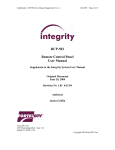
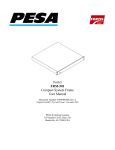
Integrity
RCP-502
Compact Remote Control Panel
User Manual
Revised January 2005
RCP-502 User Manual
Page 1
OVERVIEW
The RCP-502 Compact Remote Control Panel provides simple access to Integrity
system AV cards and frames. Though this control panel may control all cards on the
network, it is recommended for either light duty in managing multiple devices or heavy
duty when managing a single card or card pair from a remote location in your facility.
The RCP-502 may also be converted for use as a local control panel by attaching it to an
FRM-501 Compact System Frame. See addendum.
INSTALLATION
Mount the panel in a rack using the screw hardware kit provided.
Connect to an Ethernet switch using an RJ-45 patch cable. Connect the external power
supply model PSU-502 to the 5V DC input connector on the rear of the RCP-502 case.
Power will be applied immediately when you connect to an AC power source.
Compatibility
The RCP-502 utilizes an Ethernet port to connect to Integrity system frames and cards
over a dedicated 10/100 Mbps switch. The RCP-502 is compatible with the following
Integrity system products:
•
•
•
•
•
•
•
All integrity system AV cards with SW versions 8.2 or higher.
RCI-300
RCP-303
RCP-503
FRM-504
FRM-501
FRM-304 (see note 1 below)
Note 1: Older FRM-304 frames which utilize an LCP processor card must be upgraded
to the ZFCB processor card prior to operation with the RCP-502. Software upgrades to
the AV cards installed in that frame may also be required. Consult factory.
RCP-502 User Manual
Page 2
CONFIGURATION
When the vacuum fluorescent display screen lights, it will display a prompt to “Press
SETUP button to select a device”. Press [SETUP], then rotate the [SEL] knob to the
right of the VF display to scroll the window text screen up until “Set IP address” is
displayed. Select a compatible IP address for your LAN by using all four knobs to set the
address. Press [TAKE/ENTER] to save the new settings. When choosing the IP address,
make sure to be within the range of the subnet mask. Do not duplicate an address of
another device on the network. See troubleshooting tips, below.
Once the IP address is set, press [BACK] and scroll up the menu list to highlight “Select
Frame/Card” and press [MENU] to navigate to it. If no cards appear in the list, scroll to
“Discovery” and press [MENU] to refresh the list. The DISCOVERY command queries
all frames on the LAN to report their card inventories to this control panel, refreshing the
list in the RCP-502.
RCP-502 User Manual
Page 3
Control Layout
Bypass
Test
Preset
Input
ALIAS001
Two
Three
Four
Five
Six
Ref
Freeze
Setup
[Input] LED illuminates on loss of currently selected video input.
Press [Bypass] to toggle bypass mode (if allowed). Bypass LED will illuminate when
currently selected video card is in Bypass.
Press [Test] to toggle Test Out mode. Test LED will illuminate when the currently
selected video card is in Test.
Press [Preset] to snap the values in the current menu to their user default values, if
supported by software (i.e.: video gain, black level, chroma level, NTSC hue).
Press [Setup] to enter the Panel Setup menu OR press [Setup] and HOLD for >5 seconds
to hardware reset the panel.
Press [Freeze] to freeze the current video out.
Freeze LED will illuminate when the currently selected video card is in Freeze. There is
also a control in the menu tree for the freeze type (Frame, Field-1, Field-2)
[Ref] LED illuminates on loss of currently selected Genlock Reference.
Display shows up to six lines of text in each menu. The top line is the ALIAS Name of
the currently selected card, i.e. ALIAS001 or SAT27. Many menus contain more than six
lines and may be scrolled up or down by rotating the [SEL] knob.
RCP-502 User Manual
Page 4
Control Layout (continued)
Hue
Menu
Video
Take/Enter
SEL
A1
Back
Audio
Navigation in the menu tree allows the following:
[Menu] takes you deeper into the highlighted item.
[Back] takes you up one level.
[Video] takes you directly to the Video Proc Amp Screen of the current video card.
[Audio] takes you directly to the default audio gain screen of the current audio card.
[SEL] Knob is used to scroll up or down menus in the VF display. It also serves as the
[Hue] control when video proc amp is selected, or as [A1] when an audio menu is
selected.
[Take/Enter] button, when illuminated appears green, an indication that the button is
“live” and used in the current menu. Commands which do require [Take/Enter] to be
pressed will execute and the LED will turn off.
RCP-502 User Manual
Page 5
SETUP MENU
Press [Setup] to display the menu below. Rotate the [Sel] knob to highlight the desired
function and press [Menu] to select it.
PANEL SETUP
Select Frame/Card
Alarms
Panel Info
Set Brightness
Set IP Address
The currently selected (last used) card is highlighted.
Under each frame name, a list of cards appears. Each card is displayed with its slot
number, alias and card type.
SELECT CARD
Frame [192.168.0.99]
01- Alias001 FS412A
02 - Alias002 DAS-441A
03 - Alias003 FS-512
04 - Alias004 DAS441A
Scroll list using the [Sel] knob.
Press [MENU] to select highlighted card and jump to that card’s home screen.
ALARMS
PANEL SETUP
Select Frame/Card
Alarms
Panel Info
Set IP Address
RCP-502 User Manual
Page 6
Press [Menu] to enter the ALARMS submenu when highlighted.
ALARMS
Panel Alarms
Device Alarms
Scroll to select a sub list, either PANEL ALARMS or DEVICE ALARMS. Alarms
found will be displayed.
PANEL INFO
PANEL INFO
SW VERSION
8.5.1 11/01/2005
BOARD DEF FILES
FS-412A 8.5.1
DAS-441A 8.5.1
Scroll list of Board Def Files (BDF) using the Selector Knob.
Press [Back] to exit to the PANEL SETUP menu.
SET IP ADDRESS
Set Panel IP Address
192.168.0.99
EXT
Set IP address using the four soft knobs.
Press [Take/Enter] to save new value and exit, or
Press [Back] to exit the submenu to PANEL SETUP menu.
Fortel DTV
3305 Breckinridge Blvd., Suite 118
Duluth GA 30096 USA
+1 770-806-0234 VOX
+1 770-806-0244 FAX
RCP-502 User Manual
Page 7