1
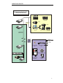
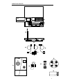
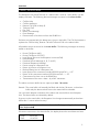
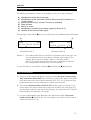
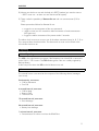
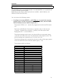
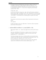
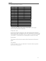
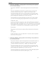
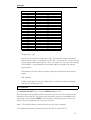
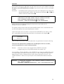
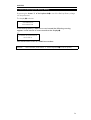
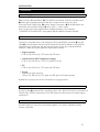
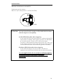
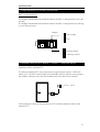
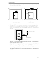
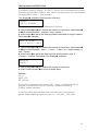
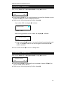
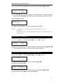
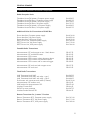
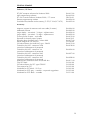
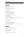
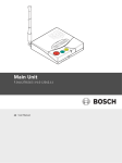
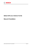
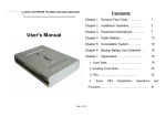
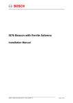
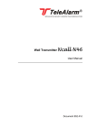
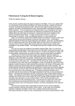
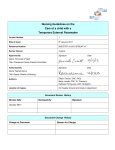
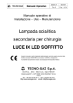
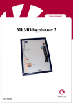
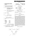
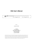
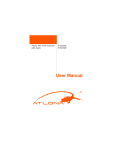
zvtelectroniç SPECIALISTS IN SECURITY-ORIENTED TELECOMMUNICATIONS TeleAlarm NurseCall User Manual Document 952.42f OPERATING DEVICES The Reception Unit NurseCall complies with Part 15 of the FCC Rules: FCC ID: MIYNC2 This device complies with Part 15 of the FCC Rules. Operation is subject to the following two conditions: 1) This device may not cause harmful interference, and 2) this device must accept any interference received, including interference that may cause undesired operation The Minitransmitter S37 complies with Part 15 of the FCC Rules: FCC ID: MIYS37 This device complies with Part 15 of the FCC Rules. Operation is subject to the following two conditions: 1) This device may not cause harmful interference, and 2) this device must accept any interference received, including interference that may cause undesired operation The Minitransmitter S35, the Smoke Detector SD and the Wireless Contact RAC comply with Part 15 of the FCC Rules: FCC ID: MIYMOD-10 This device complies with Part 15 of the FCC Rules. Operation is subject to the following two conditions: 1) This device may not cause harmful interference, and 2) this device must accept any interference received, including interference that may cause undesired operation The Wall Transmitter N45 complies with Part 15 of the FCC Rules: FCC ID: MIYN45 This device complies with Part 15 of the FCC Rules. Operation is subject to the following two conditions: 1) This device may not cause harmful interference, and 2) this device must accept any interference received, including interference that may cause undesired operation TeleAlarm NurseCall : User Manual, Document No 952.42f, Edition: June 28, 2002, TELECTRONIC SA 2002, all rights reserved. TELECTRONIC SA reserves the right to make changes in the information contained in this document at any time without prior notice. Great care has been given to the contents of this document; however TELECTRONIC SA cannot be held liable for the consequences of any errors or omissions contained herein or for consequential or incidental damages incurred as a result of acting on information contained in the document. TeleAlarm® is a registered trade mark of TELECTRONIC SA. The NurseCall is manufactured in La Chaux-de-Fonds (Switzerland) by TELECTRONIC SA. FIDELITY TELEALARM CORP. TELECTRONIC SA READING, PA 19605 2300 LA CHAUX-DE-FONDS US DISTRIBUTOR HEAD OFFICE, PRODUCTION, R&D 2501 Kutztown Road Rue du Nord 176 Tel.: (610) 921-8697 Fax: (610) 929-6860 Tel.: +41 32 911-1111 Fax: +41 32 911-1100 2 OPERATING DEVICES Wireless NurseCall system Technical overview Periphery RS232 DECT handsets Paging system (in house) Printer RS232 Master Printer Slave 1 PC-RUF DECT handsets Paging system (in house) RS485-Bus Radio transmitters Radio S37L Locator Mini-Transmitter S35 Mini-Transmitter S37 Slave 32 Smoke Detector SD Large displays RS232 Wall transmitter NCall N45 Printer Door Contact RAC Printer Interface 3 OPERATING DEVICES 9 :+ 9V 1 abc _ 6 pqr V TeleAlarm 6 7 ® 2 def 7 stu 3 ghi 8 vwx 4 jkl 9 yz. NurseCall 5 mno 0 -_+ 3 1 2 8 4 5 ; <= > A ? @ C B V Ncall G F D E H 4 OPERATING DEVICES NurseCall : Reception Unit 1 2 3 4 5 6 7 8 9 : ; < = > ? @ A B C White Button, Erase Button Green Button, Confirm Button Display Button « Volume higher » Button « Volume lower » Selection Button 1 Selection Button 2 Keyboard Cursor Backup Battery Antenna RS485-Connection Power Connection Output Relay RS232-Connection Cable to RS485-Connection Power Supply Plug Power Supply Cable to RS232-Connection (not delivered by default) NurseCall : Transmitters D E F G H Wall Transmitter NCall N45 Minitransmitter S35 Minitransmitters S37 / S37L (with or without « locate » function / dementia alarm) Smoke Detector SD Wireless Contact RAC 5 CONTENT BRIEF DESCRIPTION MANUAL Alarm- and Event Buffer Display Indications Re-set Possibilities Signaling RS232-Interface RS485-Interface Control of Rechargeable Backup Battery Function « Locator » / Dementia Alarm General 9 10 10 11 12 22 24 25 25 INSTALLATION Installation Connections Backup Battery Features of Portable Minitransmitters S35 and S37 Jumper Definitions for Wireless Contact RAC Installation Hints for IS75 Module (« Locator » / Dementia Alarm) How to Change Transmitter Battery 26 27 28 28 31 31 35 PROGRAMMING INSTRUCTIONS Start Up Selection Locate Function YES or NO Programming Mode Programming « Date and Time » Programming « Correspondence Transmitter - Location » Programming « Choice RS232-Connection » Programming « Local Re-set » Programming « Remote Re-set » Programming « Language » Programming « Relay as Closing or Switching Contact » Erase All Parameters Default Parameters Programming Software 39 39 40 41 42 43 46 46 47 47 48 48 49 GENERAL REMARKS Cleaning Storage Reference Numbers NurseCall Components Software Versions Edition Declaration of Conformity 50 50 51 53 54 55 6 BRIEF DESCRIPTION ! TeleAlarm NurseCall : Your modern, wireless nurse call system The system TeleAlarm NurseCall offers an excellent solution for the care and organization in homes for elderly people, clinics or hospitals. The following peripheral devices are available to transmit different alarms/messages to the Reception NurseCall Unit. • • • • • Wall Transmitter NCall N45 (different alarms/messages) D Minitransmitter S35 (Call for Help) E Minitransmitter S37 (Call for Help) and Minitransmitter S37L (dementia alarm) F Smoke Detector SD (Fire Call) G Wireless Contact RAC (Call for Help) H As a radio system it is highly flexible and easily installed. The Wall Transmitter NCall N45 with up to 13 different alarms/messages solves several tasks in your system. The Minitransmitters S37 and S35 can be worn all the time. The Minitransmitter S37 does not disturb while you are sleeping. Both Minitransmitters are waterproof, even in your bath. The Minitransmitters S37 can be equipped with the locate option (version S37L). You can not only identify who triggered a call for help, but also where the person is at the moment. It is also possible to generate an automatic alarm when a person approaches a door/zone which should not be exited (dementia alarm). A maximum of 300 transmitters can be controlled by the Reception Unit NurseCall. In its simplest configuration the Reception Unit can handle the incoming data as stand-alone unit (indication at the display 3 and in addition acoustic signaling). If the Reception Unit is connected to other devices by the RS232-Interface ? the information is additionally transmitted to these devices. Several configurations are possible to meet your needs (see System Overview on page 3). The chapter RS232-Interface explains the connection possibilities to a paging system / DECT telephone system / printer / PC with corresponding software. The chapter RS485-Interface explains the connection of several Reception Units together in one system (master-slave configuration). The following information at the arrival of an alarm/message is available at the display / transmitted to the connected devices: Identification of alarm/message Floor number / room number / bed number or a single number Actual position of person who has triggered the alarm Date and time Quality of the received radio signal Type of storage (alarm or event) Identification of the unit which has received the alarm/message (master / slave) 7 BRIEF DESCRIPTION The correspondence transmitter ↔ floor number / room number / bed number or single number can be freely chosen (0 to 254). The correspondence is programmed together with the Reception Unit in a first step. The radio reception range is in general sufficient with the antenna supplied ;. This coverage depends on the distance and the construction material of your building. If you wish to improve your radio reception range two solutions can be offered: a) Master - Slave connection of several Reception Units. Further Reception Units (slaves) can be connected together with the main Reception Unit (master) with the help of the RS485-Interface <. The maximum distance between the two most distant Reception Units can be up to 4000 feet. b) Install the antenna remotely with a magnetic support. Remark: To achieve an improvement with remote antennas some basic rules have to be followed. For correct installation contact a specialist. 8 MANUAL ! Alarm- and Event Buffer The Reception Unit NurseCall uses an « alarm buffer » and an « event buffer » for the display indication. The following alarms/messages are stored in the alarm buffer: • • • • • • • • Call for Help Call for Assistance Reserve Call (Call for Help 2) Technical Call Fire Call Battery Low Message Error Message Disconnection of a slave unit from the RS485-bus If alarms are repeated only the oldest entry is kept in the buffer. The Call for Assistance replaces the Call for Help, Reserve Call and Technical Call in the alarm buffer. All possible entries are stored in the event buffer. The following messages are directly stored in this buffer: • • • • • • • • • • • • • Re-set Call (Re-set N45) Re-set Call (Re-set S35/S37) Local Re-set (Re-set at the Reception Unit NurseCall) Daily Message Personnel Arrival Message (A, B, C and D) Personnel Departure Message Power outage of a Reception Unit Return of power at a Reception Unit Backup Battery Low of a Reception Unit Interruption of the connection interface RS232 NurseCall <-> PC Return of the connection interface RS232 NurseCall <-> PC Connection of a slave unit to the RS485-bus Transmission of the event « door » by a RAC transmitter The alarm and event buffer have a capacity of max. 18 entries. Remark: The event buffer will normally be filled with the last 18 entries, in the alarm buffer only the alarms which have to be treated will be indicated. You can switch between indication of the alarm and event buffer at the Reception Unit. The alarm buffer is indicated by default. If you are in the event buffer, the Reception Unit changes automatically to the alarm buffer after 1 minute without activity! ! You can switch between alarm and event buffer by pressing the button ‘0’ of the keyboard 8. If there are no entries in the alarm buffer, the display shows the actual date and time. DATE: TIME: 05.02.02 09:45:30 9 MANUAL ! Display Indications The following information is shown at the display on entry of an alarm/message: A) Identification of the alarm/message B) Identification of the transmitter location (floor/room/bed number or a single number) C) Actual position (only if “Locator” function is activated) D) Date and time E) Alarm- or event F) Identification reception from master (space) or slave (A...f) G) Quality of the received radio signal By pressing the white button 1 you can switch between the available information blocks. A) HELP E) A03 FL: 012 RO: 015 BE: 001 B) Information block 1 HELP 03.03.02 D) A03 23:35:56 F) C2 G) Information block 2 Remark 1: In the alarm buffer the sum of entries is indicated on top at the right. You can immediately see how many alarms still have to be treated (in the example above: there are totally 3 alarms in the alarm buffer). On the event buffer the position of the event in the buffer is indicated (E01 corresponds to the last entry in the event buffer). To view the alarm or event buffer use button 6 (upwards) and 7 (downwards). ! Re-set Possibilities A) The re-set of the alarms/messages is done by pressing the green button of the Wall Transmitter NCall N45 if this transmitter is used in your system. The NCall N45 allows also the re-set of other transmitters (S35, S37, etc.) if they have been programmed with the same identification number (same location). B) The portable Minitransmitters S35 and S37 can be re-set by a magnet. To reset the alarm, the magnet needs to be swept over the LED in the case of the S37, over the black marking at the side of the housing in the case of the S35. The LED blinks rapidly if this operation is successful. C) A re-set is also possible at the Reception Unit itself with the help of the green Confirm Button 2 (Local Re-set). You can choose if you have to enter a code to enable this function or not. 10 MANUAL D) Alarms can also be re-set with the help of a DECT handset (you need to insert a « DECT re-set unit » as slave unit into the NurseCall system). E) There is also the possibility of Remote Re-set with a re-set transmitter (S35 or S37). Please proceed as follows for Remote Re-set: • trigger the re-set transmitter of the care personnel. • respect a time-out of 2 seconds to allow termination of radio transmission (LED goes out). • trigger the alarm transmitter of the patient within 5 seconds. The alarm which receives a re-set in one of the above mentioned ways (A, B, C, D or E) is removed from the alarm buffer. The alarm and its re-set can be found in the event buffer from then on. ! Signaling ! Visual Signaling The LED in the right button turns green if the Reception Unit NurseCall is connected to the 230 V / 120 V mains. This LED flashes green if the unit is solely supplied by Backup Battery. At the entry of an alarm the LED in the left button turns red. ! Buzzer The internal buzzer is activated at the reception of the following alarms/messages (until re-set). Continuously, two tones: • Call for Assistance • Fire Call 4 second interval, one tone: • Call for Help • Reserve Call • Technical Call 15 second interval, one tone: • Error Message 30 second interval, one tone: • Battery Low Message 1 minute interval, one tone: • Disconnection of a slave unit from the RS485-bus 11 MANUAL At the entry of one of the other messages (→ event buffer) a short beep is emitted: • • • • • • • • • • • • • Re-set Call (Re-set N45) Re-set Call (Re-set S35/S37) Local Re-set Daily Message Personnel Arrival Message Personnel Departure Message Power outage of a Reception Unit Return of power at a Reception Unit Backup Battery Low of a Reception Unit Interruption of the connection interface NurseCall <-> PC Return of the connection interface NurseCall <-> PC Connection of a slave unit to the RS485-bus Transmission of the event « door » by a RAC transmitter ! Volume Adjustment The volume can be adjusted with the buttons 4 (« Volume higher ») and 5 (« Volume lower ») of the keyboard. ! Output Relay At the back of the housing a potential free contact is available. It is a low current switching contact. The relay > (potential free, switching power: max. 48 V / 0.5 A) is activated at a Call for Help, Call for Assistance or Fire Call. It can be programmed if the relay has to function as closing or switching contact (cycle of 10 seconds on / 10 seconds off). ! RS232-Interface A 9-pole SUB-D connector ? at the back of the housing can be used for connection to a • • • • paging system DECT telephone system printer PC with corresponding software ! Printer To protocol all events a printer with serial connection (RS232-Interface) and endless paper should be used. Printers with a parallel port can be used together with an intermediate serial - parallel converter. The paper printout corresponds to the indication at the display of the Reception Unit NurseCall. Data rate is 9600 Bauds. Transmission is asynchron with a 10 bit-structure (1 startbit, 8 databits without parity, 1 stopbit). The availability of the printer cannot be tested (switched on/off, paper). TELECTRONIC recommends the use of the following printers: • SCRIPTOS (can be bought at TELECTRONIC). 12 MANUAL ! DECT Telephone System The NurseCall system can transfer the received alarms to type Multitone CH70 DECT handsets. Configuration : • Multitone DECT system CS600 and interface P318 The protocol “DECT” needs to be programmed to the NurseCall master unit. Data rate is 9600 Bauds. Transmission is asynchron with a 10 bit-structure (1 startbit, 7 databits with even parity, 1 stopbit) in the half-duplex mode. The alarms/messages which enter in the alarm buffer are transmitted (except « slave off ») as well as the re-set. The transmission is fully alpha-numeric. The alarms/messages are repeated every 3 minutes until re-set. The transmission to the DECT system takes place as a team call. The team number must match the paging group programmed for every single transmitter. Change day / night If you have activated the change day / night, the NurseCall system transfers all alarms during « night » to the group 24. At « day », all groups 00 - 24 can be used. At the moment of the switching from « day » to « night » or vice versa, the message « DAY-NIGHT » is transmitted to the activated DECT handsets to signalize the change. Priority alarms The assistance and fire alarm are priority calls and transmitted to all activated DECT handsets. Call repetition If alarms/messages are not re-set after about 7 minutes the calls are repeated and also sent to the group 23. 13 MANUAL ! Paging System The NurseCall system uses several protocols : the standard ESPA 4.4.4. protocol and a specific Multitone protocol (MEP). Depending on the version, further protocols are available : Alpha2 (Bosch), Line (Philips) and DeTeWe (DeTeWe). You can connect the following systems : • If configured correctly (RPE670 = NO, ESPA 4.4.4.) most of the common paging systems can be connected (Ascom, Ericsson, Blick, Siemens DAKSServer, Multitone Access 3000 Compact, etc.) The protocol “ESPA 4.4.4.” needs to be programmed to the NurseCall master unit. Data rate is 9600 Bauds. Transmission is asynchron with a 10 bit-structure (1 startbit, 7 databits with even parity, 1 stopbit) in the half-duplex mode. Pagingsystem-ID = 2, NurseCall-ID=1 ; The alarms/messages which enter in the alarm buffer are transmitted (except « slave off ») as well as the re-set. The transmission is fully alpha-numeric. The alarms/messages are repeated every 3 minutes until re-set. The alarms/messages are transmitted to the team number of the paging system which was attributed to the transmitter (default group = 00). The attribution table is as follows : group 00 01 02 03 04 05 06 07 08 09 10 11 12 13 14 15 16 17 18 19 20 21 22 23 24 team number 999 998 997 996 995 994 993 992 991 990 989 988 987 986 985 984 983 982 981 980 979 978 977 976 975 14 MANUAL If using the version NurseCall Europe II (see chapter “software versions”) it is possible to choose the number of digits for the team number (2-, 3- or 4- digit indication). By default 3 digits are set. If you select 2 digits the calls are transmitted to teams 99 – 75, if you select 4 digits they are transmitted to teams 9999 – 9975. Change day / night If you have activated the change day / night, the NurseCall system transfers all alarms during « night » to the group 24. At « day », all groups 00 - 24 can be used. At the moment of the switching from « day » to « night » or vice versa, the message « DAY-NIGHT » is transmitted to the activated pagers to signalize the change. Priority alarms The assistance and fire alarm are priority calls and transmitted to all activated pagers. Call repetition If alarms/messages are not re-set after about 7 minutes the calls are repeated and also sent to the group 23. • Multitone RPE670 with ESPA 4.4.4. protocol (RPE670 = YES) The protocol “ESPA 4.4.4.” needs to be programmed to the NurseCall master unit. Data rate is 9600 Bauds. Transmission is asynchron with a 10 bit-structure (1 startbit, 7 databits with even parity, 1 stopbit) in the half-duplex mode. Pagingsystem-ID = 2, NurseCall-ID=1 ; The alarms/messages which enter in the alarm buffer are transmitted (except « slave off ») as well as the re-set. The transmission is fully alpha-numeric. The alarms/messages are repeated every 3 minutes until re-set. The alarms/messages are transmitted to the team number of the Multitone system which was attributed to the transmitter (default group = 00). 15 MANUAL The attribution table is as follows : group 00 01 02 03 04 05 06 07 08 09 10 11 12 13 14 15 16 17 18 19 20 21 22 23 24 Team number 12GG 13GG 14GG 15GG 16GG 17GG 18GG 19GG 20GG 21GG 22GG 23GG 24GG 25GG 26GG 27GG 28GG 29GG 30GG 31GG 32GG 33GG 34GG 35GG 36GG In indication mode « floor / room / bed » use only alpha-numeric pagers which can store more than 16 characters. Change day / night If you have activated the change day / night, the NurseCall system transfers all alarms during « night » to the group 24. At « day », all groups 00 - 24 can be used. At the moment of the switching from « day » to « night » or vice versa, the message « DAY-NIGHT » is transmitted to the activated pagers to signalize the change. Priority alarms The assistance and fire alarm are priority calls and transmitted to all activated pagers. Call repetition If alarms/messages are not re-set after about 7 minutes the calls are repeated and also sent to the group 23. 16 MANUAL • Multitone RPE670 with MEP protocol The protocol “MEP” needs to be programmed to the NurseCall master unit. Data rate is 1200 Bauds. Transmission is asynchron with a 10 bit-structure (1 startbit, 7 databits with even parity, 1 stopbit) in the half-duplex mode. The alarms/messages which enter in the alarm buffer are transmitted (except « slave off ») as well as the re-set. The transmission is only numeric. The alarms/messages are repeated every 3 minutes until re-set. The alarms/messages are transmitted to the Multitone team number which was attributed to the transmitter (default group = 00). The attribution table is as follows : Gruppe 00 01 02 03 04 05 06 07 08 09 10 11 12 13 14 15 16 17 18 19 20 21 22 23 24 Teamnummer 12GG 13GG 14GG 15GG 16GG 17GG 18GG 19GG 20GG 21GG 22GG 23GG 24GG 25GG 26GG 27GG 28GG 29GG 30GG 31GG 32GG 33GG 34GG 35GG 36GG Use pagers with « alpha-text » and which are coded as follows: Code 00 06 09 02 15 07 03 01 04 Alarm/message Re-set Call for Help Call for Assistance Reserve Call Technical Call Fire Call Battery Low Message Error Message DAY-NIGHT message to signalize the change day ↔ night. 17 MANUAL The transmission takes only place in indication mode: « single number for location of the transmitters » . Change day / night If you have activated the change day / night, the NurseCall system transfers all alarms during « night » to the group 24. At « day », all groups 00 - 24 can be used. At the moment of the switching from « day » to « night » or vice versa, the message « DAY-NIGHT » is transmitted to the activated pagers to signalize the change. Priority alarms The assistance and fire alarm are priority calls and transmitted to all activated pagers. Call repetition If alarms/messages are not re-set after about 7 minutes the calls are repeated and also sent to the group 23. • If selecting “Alpha2”, paging systems communicating in this protocol can be connected (Bosch). The protocol “Alpha2” needs to be programmed to the NurseCall master unit. Data rate is 4800 Bauds. Transmission is asynchron with a 10 bit-structure (1 startbit, 8 databits without parity, 1 stopbit) in the half-duplex mode. The alarms/messages which enter in the alarm buffer are transmitted (except « slave off ») as well as the re-set. The transmission is fully alpha-numeric. The alarms/messages are repeated every 3 minutes until re-set. The alarms/messages are transmitted to the team number of the paging system which was attributed to the transmitter (default group = 00). 18 MANUAL The attribution table is as follows : group 00 01 02 03 04 05 06 07 08 09 10 11 12 13 14 15 16 17 18 19 20 21 22 23 24 team number 999 998 997 996 995 994 993 992 991 990 989 988 987 986 985 984 983 982 981 980 979 978 977 976 975 Change day / night If you have activated the change day / night, the NurseCall system transfers all alarms during « night » to the group 24. At « day », all groups 00 - 24 can be used. At the moment of the switching from « day » to « night » or vice versa, the message « DAY-NIGHT » is transmitted to the activated pagers to signalize the change. Priority alarms The assistance and fire alarm are priority calls and transmitted to all activated pagers. Call repetition If alarms/messages are not re-set after about 7 minutes the calls are repeated and also sent to the group 23. 19 MANUAL • If selecting “LINE PROT.”, paging systems communicating in this protocol can be connected (Philips). The protocol “LINE PROT.” needs to be programmed to the NurseCall master unit. Data rate is 9600 Bauds. Transmission is asynchron with a 10 bit-structure (1 startbit, 8 databits without parity, 1 stopbit) in the half-duplex mode. The alarms/messages which enter in the alarm buffer are transmitted (except « slave off ») as well as the re-set. The transmission is fully alpha-numeric. The alarms/messages are repeated every 3 minutes until re-set. The transmission to the system takes place as a team call. The team number must match with the paging group programmed for every single transmitter. Change day / night If you have activated the change day / night, the NurseCall system transfers all alarms during « night » to the group 24. At « day », all groups 00 - 24 can be used. At the moment of the switching from « day » to « night » or vice versa, the message « DAY-NIGHT » is transmitted to the activated pagers to signalize the change. Priority alarms The assistance and fire alarm are priority calls and transmitted to all activated pagers. Call repetition If alarms/messages are not re-set after about 7 minutes the calls are repeated and also sent to the group 23. • If selecting “DeTeWe”, paging systems communicating in this protocol can be connected (DeTeWe). The protocol “DeTeWe” needs to be programmed to the NurseCall master unit. Data rate is 9600 Bauds. Transmission is asynchron with a 10 bit-structure (1 startbit, 8 databits with odd parity, 1 stopbit) in the half-duplex mode. The alarms/messages which enter in the alarm buffer are transmitted (except « slave off ») as well as the re-set. The transmission is fully alpha-numeric. The alarms/messages are repeated every 3 minutes until re-set. The alarms/messages are transmitted to the team number of the paging system which was attributed to the transmitter (default group = 00). 20 MANUAL The attribution table is as follows : group 00 01 02 03 04 05 06 07 08 09 10 11 12 13 14 15 16 17 18 19 20 21 22 23 24 team number x00 x01 x02 x03 x04 x05 x06 x07 x08 x09 x10 x11 x12 x13 x14 x15 x16 x17 x18 x19 x20 x21 x22 x23 x24 The value x can be programmed (between 0 –9). Change day / night If you have activated the change day / night, the NurseCall system transfers all alarms during « night » to the group 24. At « day », all groups 00 - 24 can be used. At the moment of the switching from « day » to « night » or vice versa, the message « DAY-NIGHT » is transmitted to the activated pagers to signalize the change. Priority alarms The assistance and fire alarm are priority calls and transmitted to all activated pagers. Call repetition If alarms/messages are not re-set after about 7 minutes the calls are repeated and also sent to the group 23. ! PC Software The software PC-RUF of the company ASS/Germany is used. The interruption of the RS232-Interface connection and its return are indicated at the Reception Unit NurseCall. The buzzer of the NurseCall master unit is disabled at the connection of the software PCRUF of ASS/Germany. The alarms which enter in the alarm buffer are repeated every 3 minutes until re-set. Note : The technical alarm is treated as an event (no re-set necessary). For additional information, please refer to the PC-RUF manual 953-18. 21 MANUAL ! RS485-Interface Further Reception Units (up to 32 slave units) can be connected together with the help of the RS485-connection < and the delivered cable @ (cable with two FCC 6/4 plugs). The bus is connected to the two exterior wires of the FCC 6/4 plug. Remark: Keep polarity equal when connecting further units to the RS485 bus! The max. distance on the RS485-bus is 4000 feet. Use only twisted two pair cable for the interconnection. The two Reception Units which are located at the two ends of the bus need to be terminated with a 100 Ω resistor (set jumper 5 at the inside of the Reception Units). In this master-slave configuration you always need to connect the master unit first. The slave units must then be connected to the RS485-bus one after the other (not at the same time). Connection of the slave units : Connect first the Backup Battery of the slave unit. Push the white button while the display shows the following indication : →+ SLAVE ID █ Identification ( █ or A ... f ) -← The identification must then switch to a black field █. After pushing the green button, the display shows : TELEALARM SLAVE OFF ! ! ! You can now connect the power supply and then to the RS485-bus. The identification number of the slave units corresponds to the order of connection (A to f for a max. of 32 slave units). At the introduction of a new slave unit the next higher identification number is attributed. 22 MANUAL If you need to change an old slave unit with a new one you can re-attribute manually the prior, reserved identification number (if you do not wish to use the next higher number). Procedure : Immediately after supplying the power to the Reception Unit choose the desired identification number with the help of the buttons 4 and 5 and confirm with the Confirm Button 2. Attention : If you connect a slave unit which had already been installed (connection to an other master unit) you need to re-set the slave unit before attributing it to the new system. Procedure : Select the black field █ for the identification . At the entry of a new alarm/message the alarm and event buffers of all Reception Units are updated. The power outage of one of the interconnected Reception Units is transmitted to the rest of the Reception Units (with identification number). At the interruption of a unit which is connected to the RS485-bus an alarm « slave off » is generated and the disconnected slave unit indicates at the display 3 TELEALARM SLAVE OFF ! ! ! After a further 4 minutes the disconnected slave unit generates an acoustic warning. To ensure the transmission quality from one Reception Unit to an other, consult a specialist for correct interconnection. Remark: The slave units are not equipped with a RS232 connection. Programming can only be effectuated at the master unit. You can add a « Printer Interface » to the RS485-bus to connect an additional printer or a large display (see System Overview, page 3). In this configuration an in house paging system can be combined with a printer without having to use a PC. The « Printer Interface » does not use up any slot in the identification table of the slave units. Attention : To change the language or the indication mode you need to re-set the « Printer Interface » . Procedure : Enter the combination « 234 » and confirm the re-set. 23 MANUAL ! Control of Rechargeable Backup Battery By pressing the button ‘9’ of the keyboard 8 a test of the Backup Battery voltage can be performed. The display 3 indicates: CONTROLLING ACCUMULATOR If the Backup Battery is defective or not inserted the following warning appears in the interval of some seconds at the display 3: CHANGE ACCUMULATOR Nurse-Call 2 You should insert a new 9 V NiMH accumulator. Remark: After insertion press button ‘9’ of the keyboard 8 to test its quality. 24 MANUAL ! Function « Locator » / Dementia Alarm The NurseCall system can optionally be delivered with the « Locator » function. Beacon modules IS75 need to be installed on doors or corridors in the building you want to supervise. When passing one of these modules the Minitransmitter S37L refreshes its actual position. At alarm triggering the Minitransmitter S37L does not only transmit its identification (who sent the alarm), but also the position of the last passed module (where was the alarm triggered). At the entry of a call the information of the actual position is indicated additionally. This information can be made visible by pressing the white button 1 (three information blocks instead of two). The location information is available on all units of the NurseCall system (Master, Slave and Printer Interface). Third information block : HELP A03 POS: 077 255 positions (POS : 000 - 254) can be differentiated. When passing beacon modules with position numbers 230 - 254 the Minitransmitter S37L can send a call for help automatically without manual activation (dementia alarm). With the help of the clip S37 the Minitransmitter S37L can be worn around the neck or at the belt. ! General Depending on the project a NurseCall system can be composed of very different elements. In the chapters “Reference Numbers NurseCall Components” and “Software Versions” you will find an overview about the possible elements. 25 INSTALLATION ! Installation Install the Reception Unit NurseCall in a dry place, away from any source of heat. ! Installation on a piece of furniture It is recommended to put the Reception Unit NurseCall on a non-sliding surface. Avoid immediate proximity with other electric devices such as television. The antenna ; shall never be removed. ! Wall installation The Reception Unit NurseCall is fixed by means of two screws. The design below indicates the position of the screws. At the bottom of the housing there are two channels provided for cables. 8,07 inch D = 0,16 inch 1,57 inch D =0,32 inch 6,30 inch 1,50 inch 26 INSTALLATION ! Connections ! Power Supply First, insert the Backup Battery : (9 V NiMH accumulator). Slide the movable cover 9 to the right by slightly raising the left end in order to free it from the catch. Switch the Power Supply Plug A into the Power Connection = of the Reception Unit NurseCall and the Power Supply B into a 230 V / 120 V socket. If you connect the Power Supply before the Backup Battery, the indication « CHANGE ACCUMULATOR » may appear (Backup Battery insertion too late). ! RS232-Connection Connect the intended device with the help of the 9-pole RS232 connector ? and the cable C to the Reception Unit NurseCall. Inside the NurseCall Master unit the RS232 interface can be configured with the help of jumpers. If you use a standard RS232 cable (PC cable) the jumper positions need to be as follows : • Paging systems -> TxD on (3), RxD on (2), CTS open and RTS open • Interface P318 (DECT telephone system) -> TxD on (2), RxD on (3), CTS on (7) and RTS on (8) • PC -> TxD on (2), RxD on (3), CTS open and RTS open • Printer Depends on type of printer (TxD on (3), RxD on (2), CTS open and RTS open for Scriptos printer) By default the jumpers are set for connection to a paging system. ! Output Relay An output relay > (potential free, switching power: max. 48V/0.5A) which is activated at a Call for Help, Call for Assistance or Fire Call allows the connection of a simple paging system/siren. ! RS485-Connection Several Reception Units can be connected together. For correct installation please contact a specialist. 27 INSTALLATION ! Backup Battery It is very important that the Reception Unit NurseCall is always equipped with a Backup Battery (9 V NiMH accumulator). The Backup Battery is checked automatically by the Reception Unit once a day. At power outage the Backup Battery assures an autonomy of about 5 hours. « CHANGE ACCUMULATOR » indicates a 48 hours lasting charge period of the Backup Battery by the Power Supply of the Reception Unit. If after this period the indication « CHANGE ACCUMULATOR » still appears you need to change the Backup Battery. To change the Backup Battery : (9 V NiMH accumulator) slide the movable cover 9 to the right by slightly raising the left end in order to free it from the catch. Remark: After insertion of the new Backup Battery press button ‘9’ of the keyboard 8 to test its quality. ! Features of Portable Minitransmitters S35 and S37 Overview of possible versions Reference number S35 : Standard with magnet re-set SB.037.FI • With detachable cord • Sends re-set signal by radio if magnet sweeps over black marking Without magnet re-set • With detachable cord • Cannot be re-set by magnet SB.023.FI Without cord • With metal ring to connect other types of cords • Cannot be re-set by magnet SB.033.FI S37 : Standard with magnet re-set • Sends re-set signal by radio if magnet sweeps over LED SB.427.FI Without magnet re-set • Cannot be re-set by magnet SB.423.FI 28 INSTALLATION S37L : Standard with magnet re-set • Automatic alarm if door beacon with ID number > 230 is passed • Transmission of the last passed door beacon in case of manual triggering • Sends re-set signal by radio if magnet sweeps over LED • Activation of feature by : Resistors R18 and R12 set SB.424.FI Without Dementia Alarm • No automatic alarm if door beacon with ID number > 230 is passed (for persons who are allowed to pass these doors/zones) • Transmission of the last passed door beacon in case of manual triggering • Sends re-set signal by radio if magnet sweeps over LED • Activation of feature by : Resistors R17 and R12 set SB.425.FI Only Dementia Alarm • Automatic alarm if door beacon with ID number > 230 is passed • Transmission of position 000 in case of manual triggering • Sends re-set signal by radio if magnet sweeps over LED • Activation of feature by : Resistors R18 and R8 set SB.426.FI With no manual trigger SB.428.FI • Automatic alarm if door beacon with ID number > 230 is passed • No transmission in case of manual triggering • Sends re-set signal by radio if magnet sweeps over LED • For programming issues : To force a call for help, hold the magnet during at least 10 seconds directly over the LED. 29 INSTALLATION Selection of the features on the S37L Emplacement of the resistors : R8 ↔ R12 (470 Ohm) and R17 ↔ R18 (100 kOhm) R8 R12 R17 R18 LED ATTENTION : You can set two function modes on all portable Minitransmitters with the magnet re-set capability. A) With LED blinking after alarm triggering In this mode the state of the Minitransmitter is indicated by the LED (state of alert or standby). After triggering an alarm, the LED blinks at 3 second intervals until the unit is re-set by the magnet. The alarm is also repeated by radio as long as the unit is not re-set by the magnet (security function). After 20 minutes without magnet re-set the Minitransmitter will automatically go back to standby. B) Without LED blinking after alarm triggering In this mode the alarm is only sent out once via radio (no repetition) und the LED does not blink after the alarm transmission. You can toggle between the two modes A) and B) by triggering three times the magnet re-set within 7 seconds ! A successful switching of the mode is indicated by a fast blinking LED. 30 INSTALLATION ! Jumper Definitions for Wireless Contact RAC RAC : Jumper definitions The bridge1 represented below defines whether the RAC is configured for fire or call for help. The bridge2 represented below defines whether the RAC is configured as an opening or as a closing contact. bridge1 Call for help Fire bridge2 Closing contact Opening contact ! Installation Hints for IS75 Module (« Locator » / Dementia Alarm) Installation of the modules IS75 : The beacon modules IS75 are powered by an external power supply. A 230 VAC socket (US: 120 VAC socket) needs to be available near the spot you want to place the module. A beacon wire must be installed around the door or the corridor. 230 VAC / 120VAC IS75 When passing the beacon, the transmitters S37L read the position number of the module IS75. 31 INSTALLATION This position number can internally be set by a dip switch inside the IS75. ON 1 2 3 4 5 6 7 8 Position 1: add 128 Position 2: add 64 Position 3: add 32 Position 4: add 16 Position 5: add 8 Position 6: add 4 Position 7: add 2 Position 8: add 1 " Example above : 1x128 + 1x64 + 1x32 + 1x16 + 1x8 + 0x4 + 0x2 + 0x1 = 248 All other transmitters except the S37L transmit the position 000. • Check the LED on the top of the housing. The LED must be on (green) to indicate that the unit is ready to function. • Do not install the beacon module in exposed sunlight or where there is poor air circulation. • Normally perform ONE loop when using on doors (width dimensions typ. 1m – 1.5m) 230 VAC / 120VAC IS75 32 INSTALLATION • Do not use on metallic doors. If no alternative exists, distance the loop at least 50 centimetres from metallic doors. IS75 min. 50 cm IS75 min. 50 cm Non metallic doors • Metallic doors Take care NOT to have additional closed metallic circles in the proximity of the loop. There can be metal parts close to the loop, but they should NOT build a closed circle (for example: metal frame building a closed circle). If they do, break the circle. 230 VAC / 120VAC IS75 Power supply input Break unwelcome metallic circle ! ! ! Attention : If the unwelcome metallic circle cannot be broken, it is recommended to use TWO loops around the door. After installation the voltage measured at the power supply input of the IS75 shall NOT be below 11,5 V DC. If the voltage is below 11,5 V DC, this indicates that there are unwelcome metallic circles in the proximity. In this case, you need to use a second loop around the door. The voltage can be measured at the inner two wires of the RJ11 connector (in the middle). 33 INSTALLATION • The cable to use is not critical, diameter of 0,5 mm or 1 mm is o.k. • Do not use shielded cable for the loop. • The distance between the door and the beacon transmitter itself should be 0 – 4 meters (the closer the better). • Take care to twist the two wires between the door/corridor and the beacon transmitter itself. • You can test the field by approaching with a S37L transmitter. The LED lights up red whenever the S37L detects the entry into the electromagnetic field. The detection range should be around 1,5 to 2,5 m in front of the loop. • The person must normally pass through the door loop to be detected. In some cases, you can put the loop on the floor/ loops on side walls. In these cases, take care to use a loop surface equivalent to a door size. IS75 Loop on the floor • IS75 Two loops on side walls Two different beacon modules should have a distance of at least 3-4 m meters from each other. 34 INSTALLATION ! How to Change Transmitter Battery The battery status of all transmitters is checked constantly (not only at every triggering). If the battery level falls below a certain level, the transmitters send out a “battery low” alarm. From then on, the unit will remain functional for some more weeks; but you should replace the battery with a new one as soon as possible. ! Wall Transmitter NCall N45 The battery of the Wall Transmitter NCall N45 can easily be changed in the Connection Compartment (see User Manual Wall Transmitter NCall N45, document 952.41). Use a good quality 9V alkaline battery (for instance: Energizer). ! Minitransmitter S35 Unscrew the 4 screws of the Minitransmitter and change the battery (pay attention to insert battery with the correct polarity). Use only 3 V Lithium batteries of type CR2032 (for instance: Energizer) Attention : Danger of explosion if not inserted correctly. Change battery only with battery of the same type or proposed types. Dispose of discharged batteries safely. ! Wireless Contact RAC Open the case to change battery (pay attention to insert battery with the correct polarity). Use only 6 V Lithium-batteries: UCAR L544, DURACELL PX28L or VARTA V28PXL. Attention : Danger of explosion if not inserted correctly. Change battery only with battery of the same type or proposed types. Dispose of discharged batteries safely. ! Smoke Detector SD At the detection of a low battery condition the Smoke Detector will beep at regular intervals. From then on the device will function for about 30 days. To change the battery open the battery compartment on the back. Use only new standard 9V alkaline batteries and pay attention to insert batteries with the correct polarity! + - + I 35 INSTALLATION ! Minitransmitter S37 / S37L Electro Static Discharge Warning: The S37 contains highly sensitive electronic components. It should be opened only in an ESD protected environment with respect to the following precautions: ❏ Discharge yourself from electrostatic loads by touching a grounded conductive surface before opening the S37. ❏ Avoid touching conductive parts inside the device if not absolutely necessary. ! Opening Of The Case The S37 has a pressure back cover that has to be opened with an appropriate tool available from Telectronic (P.O. reference number SV.099.00) or “WatchManufacturing Tools” suppliers. Picture 1 Remove the wristband from the unit and insert the tool in the gap at the position as on Picture 2 and lift the back cover until it pops up. Picture 2 36 INSTALLATION ! Replacing The Battery Once the case is opened, the battery falls out of the case. You will find yourself with three different parts: $ The upper cover with the Electronic Assembly $ The back cover $ The battery, Energizer CR2025 3V or similar (P.O. reference number SV.098.00) Discard the old battery and place a new one in the back cover, the positive (+) polarity against the back cover. The negative (-) polarity will fit towards the Electronic Assembly. ! Closing The Case Adjust carefully the upper cover over the back cover with respect of the small positioning guide “A”, the battery contact and the large positioning guide “B” (see Picture 3). Close the case by pushing the covers together. Apply the same pressure all around the back cover until you hear or feel a small “snap” and the two halves are properly joined. Replace the wristband and test the unit for proper operation prior to use. Picture 3 Purchase numbers : Ref. SV.099.00 Case opener for S37 Ref. SV.098.00 Spare battery for S37 (CR2025) 37 INSTALLATION Warning: There is a risk of explosion, if the battery replacement is not done correctly ! ❏ Replace the battery only with a new one of the same or equivalent type. ❏ Discard the old batteries at an appropriate recycling point. Although the battery of the S37 can be changed by the end user, it is recommended that it be returned to an authorized Telectronic distributor for battery replacement. 38 PROGRAMMING INSTRUCTIONS ! Start Up The choice of language and the indication mode for the transmitter identification (floor / room / bed number or a single number) needs to be programmed: Remark: An input is confirmed by pressing Confirm Button 2. A false input can be corrected with the Erase Button 1. At start up the display 3 indicates: ! FRANCAIS ! ENGLISH DEUTSCH % ITALIANO % ☛ Select « ENGLISH » with button 7. The display 3 indicates: ! NUMBER FL,RO,BE % ☛ Select your indication mode for the transmitter identification with buttons 5 or 7. The indication of the date and time (indication of the alarm buffer with no entries) appears on the display. DATE: TIME: 03.03.02 09:45:30 ! Selection Locate Function YES or NO This procedure allows to switch on or off the indication of the actual position (locate function) on the NurseCall display. Attention : Switching between on and off will erase all previously programmed parameters. The selection of the locate function should therefore happen as a first step in the programming procedure. Enter the combination « 2347 » on the keyboard 8. 39 PROGRAMMING INSTRUCTIONS Next, enter the combination « 173956 » and answer the question Reset + Code ? with YES. The code required is « 173956 » again. The display 3 indicates: LOCATOR ? YES/OUI % ! NO/NON ☛ Select the locate function with buttons 5 or 7. ! Programming Mode ! Access To program the Reception Unit NurseCall you need to enter the programming mode. By pressing the combination « 234 » on the keyboard 8 you do so. By then pressing one of the buttons ‘1’ - ‘7’ you select the single parameter you wish to program. The Reception Unit does not receive any alarm/message in the programming mode !!! 40 PROGRAMMING INSTRUCTIONS The programming itself is performed with the help of menu on the display 3: 3 1 Remarks: 2 You can correct false inputs by pressing the Erase Button 1. An input is confirmed by pressing the Confirm Button 2. With this button you can go forward in the programming menu step by step until you reach the Ready State. After 90 seconds without activity the Reception Unit quits the programming mode. The pressing of a non valid button is signaled acoustically. ! Programmable Parameters You choose the parameter to program by pressing one of the button ‘1’ to ‘7’: 1 abc 6 pqr Button ‘1’: Button ‘2’: Button ‘3’: Button ‘4’: Button ‘5’: Button ‘6’: Button ‘7’: (Button ‘8’: 2 def 7 stu 3 ghi 8 vwx 4 jkl 9 yz. 5 mno 0 -_+ Date and Time Correspondence Transmitter - Location and Transmitter - User Number of Paging System Choice RS232-Connection Local Re-set Remote Re-set Language Relay as Closing or Switching Contact Enabling programming with « Nps-Software » ) ! Programming « Date and Time » After pressing the button ‘1’ of the keyboard 8 the field which can be edited appears underlined at the display 3 (month, day, year, hour, minutes or seconds): DATE: TIME: 03.03.02 09:45:30 ☛ Select the field you wish to edit with buttons 6 or 7. ☛ Scroll up with button 4 or scroll down with 5. ☛ Press Confirm Button 2 to get back to Ready State. 41 PROGRAMMING INSTRUCTIONS ! Programming « Correspondence Transmitter - Location » After pressing button ‘2’ at the keyboard 8 the display 3 indicates: WAITING FOR TRANSMITTER CODE ... ☛ Trigger the transmitter you wish to program (N45, S35, S37, RAC or SD). The display will depend on the mode you had chosen (floor / room / bed number or a single number). You can now enter the identification of the location. Indication mode floor / room / bed: FLOOR NUMBER: ███ ☛ Select the floor number with the keyboard 8 (‘000’ - ‘254’). ☛ Press Confirm button 2. ROOM NUMBER: ███ ☛ Select the room number with the keyboard 8 (‘000’ - ‘254’). ☛ Press Confirm button 2. BED NUMBER: █ ☛ Select the bed number with the keyboard 8 (‘0’ - ‘9’). ☛ Press Confirm button 2. Indication mode single number: NUMBER: ███ ☛ Select the number with the keyboard 8 (‘000’ - ‘254’). ☛ Press Confirm button 2. Remark: If you trigger a transmitter which has already been programmed the display indicates the earlier validated numbers. By pressing the Confirm Button 2 you can go ahead without change, by pressing the Erase Button 1 a new definition can be initiated. A max. number of 300 different transmitters can be controlled. Attention : Program the transmitter you need and not a distant one which is emitting occasionally. 42 PROGRAMMING INSTRUCTIONS After programming the correspondence transmitter - location, the attributed user number of the paging system needs to be programmed. If all calls are to be transmitted to one group call number the default value Paging Group : 00 can be kept. Otherwise you can program one of 25 paging groups for each transmitter. PAGING GROUP : 00 (00 - 24) ☛ Select the number with the keyboard 8 (‘00’ - ‘24’). ☛ Press Confirm button 2. ! Programming « Choice RS232-Connection » After pressing button ‘3’ at the keyboard 8 the display 3 indicates: ! PRINTER ! NONE PCRUF % OTHERS % ☛ Select RS232-Connection with buttons 4, 5, 6 or 7. ☛ Confirm your choice by pressing Confirm button 2. ☛ If you select ‘OTHERS‘ the display 3 indicates: ! S10-Du ! NONE PAGING % DECT % ☛ Select RS232-Connection with buttons 4, 5, 6 or 7. ☛ Confirm your choice by pressing Confirm button 2. ☛ If you select ‘PAGING’ the display 3 indicates: RPE 670 ? ! YES NO % ☛ Select paging system (RPE 670 or other) with buttons 5 or 7. ☛ Confirm your choice by pressing Confirm button 2. 43 PROGRAMMING INSTRUCTIONS ☛ At the next stage or if you select ‘DECT’ the display 3 indicates: PAGER DAY-NIGHT ! YES NO % ☛ Select change day - night with buttons 5 or 7. ☛ Confirm your choice by pressing Confirm button 2. ☛ If you select ‘YES’ the display 3 indicates: START OF NIGHT TIME : 20 : 00 : 00 ☛ Set start time with buttons 4, 5, 6 and 7. ☛ Confirm your choice by pressing Confirm button 2. END OF NIGHT TIME : 06 : 00 : 00 ☛ Set end time with buttons 4, 5, 6 and 7. ☛ Confirm your choice by pressing Confirm button 2. ☛ If you select ‘PAGING’ the display 3 indicates: ! ESPA 4.4.4. ! NONE ALPHA2 % MEP % ☛ Select paging protocol with buttons 4, 5, 6 or 7. ☛ Confirm your choice by pressing Confirm button 2. ☛ If you select ‘ESPA 4.4.4.’ the display 3 indicates: ! ID PAGING SYSTEM ! ID NURSECALL 2 1 ☛ Enter identification number of the paging system and the NurseCall system with buttons 6, 7 and the keyboard 8 (numbers ‘0’ - ‘9’ are possible). ☛ Press Confirm button 2 to return to Ready State. 44 PROGRAMMING INSTRUCTIONS If you select a protocol « Paging » or « DECT » you can at the end determine how many characters per information (criterion, floor, room, bed, spaces) have to be transmitted to the paging/DECT system -> filter possibility. The display 3 indicates (filtering of the criterion) : CRITER.← CRIT 07 + 0 SPACES You can choose 0-11 characters, followed by 0-9 spaces. ☛ With buttons 4 or 5 you choose the number of characters, with buttons 6 or 7 you switch between « criterion » and « spaces » . ☛ Press button 1 to get to the filtering of floor/room/bed (or single number). The display 3 indicates: INFO. : fff rrr 00b FL: 3+3 +RO: 3+1 +BE:3 ☛ With buttons 4 or 5 you choose the number of characters, with buttons 6 or 7 you switch between « floor » , « room » , « bed » (or « single number » ) and « spaces » . ☛ Press button 1 to get to the filtering of the actual position (only if « locator » function is activated). The display 3 indicates : BE POS xyz SPACES : 1 ☛ With buttons 4 or 5 you choose the number of characters. ☛ Press Confirm button 2 to return to Ready State. Example : CR_← INFO : frrb BE__POS xyz This means 2 characters for the criterion (CR), 1 space, 1 character for floor (f), 0 spaces, 2 characters for room (rr), 0 spaces, 1 characters for bed (b), 2 spaces, position indication. In case of a call for help from floor 008, room 023, bed 1 with the actual position 248 the following sequence is sent out : « HE_8231__POS_248 ». 45 PROGRAMMING INSTRUCTIONS ! Programming « Local Re-set » After pressing button ‘4’ at the keyboard 8 the display 3 indicates: LOCAL RECEIPT ! YES NO % ☛ Press button NO 5 if re-set at the Reception Unit shall be disabled or press button YES 7 if you wish to enable this function. ☛ Confirm your choice by pressing Confirm button 2. If you select ‘YES‘ the display 3 indicates: ACCESS CODE ██ ☛ Enter « 45 » . After having typed the correct number the display 3 indicates: ACCESS CODE ! YES NO % ☛ Press button YES 7 if every re-set must be done by entering the code « 45 » or NO 5 if direct re-set with the green Confirm Button 2 shall be enabled. ☛ Press Confirm button 2 to return to Ready State. ! Programming « Remote Re-set » After pressing button ‘5’ at the keyboard 8 the display 3 indicates: REMOTE RECEIPT ! YES NO % ☛ Press button NO 5 if no Remote Re-set is needed or button YES 7 if you wish to enable Remote Re-set. ☛ Confirm your choice by pressing Confirm button 2. 46 PROGRAMMING INSTRUCTIONS If you select ‘YES’ for enabling the Remote Re-set the display 3 indicates: RECEIPT CODE ! NEW ERASE % ☛ Press NEW 7 if you wish to program a new transmitter as re-set transmitter or press button ERASE 5 if all existing re-set transmitters are to be erased. The display 3 indicates: WAITING FOR TRANSMITTER CODE... ☛ Trigger the transmitter you wish to program (S35 or S37). Remark: A maximum of 5 transmitters can be programmed to be re-set transmitters. The same transmitter cannot be alarm transmitter and re-set transmitter at the same time. ! Programming « Language » After pressing button ‘6’ at the keyboard 8 the display 3 indicates: ! FRANCAIS ! ENGLISH DEUTSCH % ITALIANO % ☛ Select the language on the display indication with the buttons 4, 5, 6 or 7. The Reception Unit returns automatically to the Ready State. ! Programming « Relay as Closing or Switching Contact » After pressing button ‘7’ at the keyboard 8 the display 3 indicates: ! ON RELAY ON/OFF % ☛ Select the relay function you wish with buttons 5 or 7. ☛ Press Confirm button 2. ! HELP + ASSISTANCE ASSISTANCE% ! FIRE ☛ Choose relay activation according to alarms with buttons 5, 6 or 7. ☛ Press Confirm button 2 to return to Ready State. 47 PROGRAMMING INSTRUCTIONS ! Erase All Parameters The following procedure allows to erase all programmed parameters of the Reception Unit NurseCall. The NurseCall returns to the default state (delivery state). After pressing button ‘3’ at the keyboard 8 the display 3 indicates: ! PRINTER ! NONE PCRUF % OTHERS % ☛ Type RESET-Code « 194156 » on the keyboard 8. The display indicates: ! NO RESET ? YES % ☛ Press YES 5 to erase all programmed parameters and return to the default values. The following display stays on for 5 seconds: PLEASE WAIT Next, the display indicates the menu for choosing the language (like at start up). ! FRANCAIS ! ENGLISH DEUTSCH % ITALIANO % ! Default Parameters The following values are defined as default values: Date and time Transmitters RS232-Connection Local Re-set Remote Re-set Relay output Language Indication mode (floor/room/bed or a single number) Jumpers for RS232-Interface 01.01.02 00:00:01 none none enabled none closing contact to be defined to be defined set for connection to paging systems 48 PROGRAMMING INSTRUCTIONS ! Programming Software Telectronic offers you the possibility to program the NurseCall system with a « Nps-Software » . This software allows you to copy the whole configuration of existing systems to a new one, ordering of transmitters with your specific code or the remote programming of your system. By pressing the combination « 234 » (programming mode) and button ‘8’ of the keyboard 8 the master unit can be set to programming with « Nps-Software ». 49 GENERAL REMARKS ! Cleaning Clean the Reception Unit NurseCall from time to time with a dustcloth. Avoid cleaning products or detergents. ! Storage The Reception Unit NurseCall does not loose its programmed parameters when the power supply and the Backup Battery are disconnected. Remarks: When putting away the device, it is very important to remove the Backup Battery of the Reception Unit NurseCall. You may put away the transmitters without removing the batteries. 50 GENERAL REMARKS ! Reference Numbers NurseCall Components Radio Reception Units TeleAlarm NurseCall Master, European power supply TeleAlarm NurseCall Slave, European power supply TeleAlarm NurseCall Master, UK power supply TeleAlarm NurseCall Slave, UK power supply TeleAlarm NurseCall Master, USA power supply TeleAlarm NurseCall Slave, USA power supply RM.020.FI RM.021.FI RM.120.FI RM.121.FI RM.620.FI RM.621.FI Additional Units for Connection to RS485 Bus Printer Interface, European power supply Printer Interface, UK power supply Printer Interface, USA power supply DECT Re-set Unit, European power supply DECT Re-set Unit, UK power supply DECT Re-set Unit, USA power supply RM.016.00 RM.029.00 RM.019.00 RM.103.00 RM.113.00 RM.104.00 Portable Radio Transmitters Minitransmitter S37 with magnet re-set – black button Minitransmitter S37 with black button Minitransmitter S37L-Locator Minitransmitter S37L-Locator without dementia alarm Minitransmitter S37L-Locator only dementia alarm Minitransmitter S37L-Locator with no manual trigger SB.427.FI SB.423.FI SB.424.FI SB.425.FI SB.426.FI SB.428.FI Minitransmitter S35 with cord with magnet re-set Minitransmitter S35 with cord SB.037.FI SB.023.FI Fixed Radio Transmitters Wall Transmitter Ncall N45 Wall Transmitter Ncall N45 with relay - type 1 Wall Transmitter Ncall N45 with relay - type 2 Push button with connector and cable (3 meters) Minitransmitter S35 without cord Wall bracket for Minitransmitter S35 Wireless Contact RAC RAC45 for event message Wireless Smoke Detector SD RM.305.FI RM.306.FI RM.606.FI RM.013.00 SB.033.FI SB.X27.00 SB.004.FI RM.307.FI SB.006.FI Beacon Transmitter for „Locator“ Function Beacon Transmitter IS75, European power supply Beacon Transmitter IS75, UK power supply Beacon Transmitter IS75, USA power supply RM.101.00 RM.111.00 RM.102.00 51 GENERAL REMARKS Software / PC-Parts PC-RUF reception software for Windows 2000 NpS programming software PC with 2 serial interfaces Windows 2000 / 17'' screen Remote programming modem Switchbox Dect/Modem with accessory (C 975/C 1049/C 1072) RM.L01.00 RM.L02.00 SB.X10.00 RM.024.00 RM.025.00 Accessory Magnetic support for antenna with coax cable (3 meters) Additional antenna Large display – one-sided - 10 digits – alphanumeric Large display – two-sided - 10 digits – alphanumeric Thermo printer Scriptos – with cable Paperroll for thermo printer Scriptos Signaling lamp for Ncall N45 – without bulb Re-set magnet for S35 and S37 9V Lithium Battery for Ncall N45, type : SLM9V Coded key for N45 - resistance 560k control arrival/departure of personnel Coded key for N45 - resistance 1M control arrival/departure of personnel Coded key for N45 - resistance 2M2 control arrival/departure of personnel Coded key for N45 - resistance 4M7 control arrival/departure of personnel Modular box connection slave unit/RS485-bus Clip S37 black 3V Lithium Battery for S37: type CR2025 Case opener for S37 Wristband for S37 black - 22.5 cm Wristband for S37L gray – rivetable – improved ruggedness Wristband for S37L black - rivetable RM.004.00 RM.003.00 RM.020.00 RM.022.00 RM.012.00 RM.012.X1 RM.017.00 SV.038.00 RM.015.00 RM.018.00 RM.026.00 RM.027.00 RM.028.00 RM.011.00 SV.096.00 SV.098.00 SV.099.00 SV.009.00 SV.023.00 SV.013.00 52 GENERAL REMARKS ! Software Versions NurseCall Master Standard - RM.020.FI / RM.120.FI • • • Firmware 111-40 Languages German, French, English, Italian Re-set by PC not possible (blocked) Europe 2 - RM.220.FI • • • • Firmware 111-45 Languages Swedish, French, English, Dutch Re-set by PC not possible (blocked) Line protocol instead of MEP protocol Europe 3 - RM.320.FI / RM.620.FI • • • • • • Firmware 111-78 Languages German, French, English, Italian Re-set by PC possible Radio interference supervised Text: Bad/WC instead of Technik, Hilfe-2 instead of Notruf2, Quittung instead of OK DeTeWe protocol instead of Alpha2 protocol « Tyco » - RM.222.FI • • • • • • Firmware 111-77 Languages Swedish, French, English, Dutch Re-set by PC not possible (blocked) Line protocol instead of MEP protocol Text: Technique1 instead of Technique and Technique2 instead of Reserve Keyboard OEM Tyco NurseCall Slave Standard - RM.021.FI / RM.121.FI / RM.621.FI • • Firmware 111-42 Languages German, French, English, Italian Europe 2 - RM.221.FI • • Firmware 111-69 Languages Swedish, French, English, Dutch 53 GENERAL REMARKS Europe 3 - RM.321.FI • • • • Firmware 111-82 Languages German, French, English, Italian Radio interference supervised Text: Bad/WC instead of Technik, Hilfe-2 instead of Notruf2, Quittung instead of OK « Tyco » - RM.223.FI • • • Firmware 111-69 Languages Swedish, French, English, Dutch Keyboard OEM Tyco NurseCall Printer Interface Standard - RM.016.00 / RM.019.00 / RM.029.00 • • Firmware 111-44 Languages German, French, English, Italian Europe 2 - RM.039.00 • • Firmware 111-59 Languages Swedish, French, English, Dutch ! List of Valid Editions No. Date Editor Edition March 31, 2000 January 27, 2001 June 28, 2002 T. Ganyi T. Ganyi T. Ganyi English English English User Manual NurseCall 952.42d 952.42e 952.42f 54 GENERAL REMARKS EC Declaration of Conformity English : We declare that this product complies with the requirements of the EC Radio & Telecommunications Terminal Equipment R&TTE Directive 1999/5/EC, specifically with requirements detailed below. All modifications made without our agreement will invalidate this declaration. Type of product : Radio Receiver Product or component reference : NurseCall Type of products : Radio transmitter Product or component reference : N45 Product or component reference : S37 Product or component reference : S35 Product or component reference : RAC Product or component reference : SD Product or component reference : IS75 Deutsch : Hiermit erklären wir, dass das nachfolgend bezeichnete Erzeugnis aufgrund seiner Konzipierung und Bauart den einschlägigen grundlegenden Anforderungen der EU R&TTE Richtlinie 1999/5/EU, insbesondere nachfolgend genannten Richtlinien, entspricht. Bei einer nicht mit uns abgestimmten Änderung des Erzeugnisses verliert diese Erklärung ihre Gültigkeit. Bezeichnung des Erzeugnisses : Funkempfänger Gerätetyp/Bezeichnung der Einzelkomponenten : NurseCall Bezeichnung der Erzeugnisse : Funksender Gerätetyp/Bezeichnung der Einzelkomponenten : N45 Gerätetyp/Bezeichnung der Einzelkomponenten : S37 Gerätetyp/Bezeichnung der Einzelkomponenten : S35 Gerätetyp/Bezeichnung der Einzelkomponenten : RAC Gerätetyp/Bezeichnung der Einzelkomponenten : SD Gerätetyp/Bezeichnung der Einzelkomponenten : IS75 Français : Nous déclarons que ce produit est, dans sa conception et construction, conforme aux exigences de la directive R&TTE 1999/5/UE de l’Union Européenne, spécifiquement selon les directives et normes détaillées ci-dessous. Toute modification apportée au produit sans notre approbation annule cette déclaration. Type de produit : Récepteur radio Dénomination de l’appareil ou des composants : NurseCall Type de produits : Transmetteur radio Dénomination de l’appareil ou des composants Dénomination de l’appareil ou des composants Dénomination de l’appareil ou des composants Dénomination de l’appareil ou des composants Dénomination de l’appareil ou des composants Dénomination de l’appareil ou des composants : N45 : S37 : S35 : RAC : SD : IS75 55 GENERAL REMARKS Relevant EC Standards/einschlägige EU-Richtlinien/directives normatives EC : LVD 73/23/EEC EMC 89/336/EEC Applied Harmonised Standards/angewandte harmonisierte Normen/normes harmonisées appliquées : EN 60950 A1-A4 EN 50130-4 EN 55022 class 2 EN 61000-3-2 EN 61000-4-2 EN 61000-4-3 EN 61000-4-4 EN 61000-4-5 EN 61000-4-6 EN 61000-4-11 ETS 300220-1 ETS 300330 National Standards and Applied Technical Specifications/angewandte nationale Normen und technische Spezifikationen/normes nationales et spécifications techniques appliquées : -/Under the manufacturer responsibility/diese Erklärung wird verantwortlich für den Hersteller/sous la responsabilité du producteur TELECTRONIC SA rue du Nord 176 CH-2300 La Chaux-de-Fonds this conformity statement is declared by/abgegeben durch/la conformité est déclarée par P. A. Nicati Management/Geschäftsführung/Direction .............................. (Place/Ort/lieu) .................... (Date/Datum/date) ............................................. (Signature/Unterschrift/signature) 56