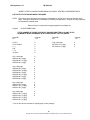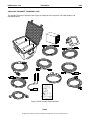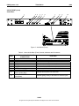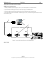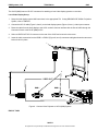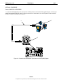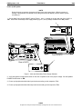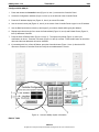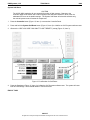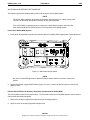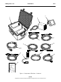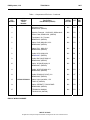
1
TM 95263 00 TECHNICAL MANUAL OPERATOR AND FIELD MAINTENANCE MANUAL FOR Audio-Visual Component System (AVCS) 33 Kings Highway, Orangeburg, NY 10962 ISO 9001: 2000 Registered Phone: 845-359-6066 Quality Management System Fax: 845-365-2114 Hotline: 800-977-3647 Web: www.drash.com DHS MANUAL PART NUMBER 95263 00 Email: [email protected] 18 SEP 2008 DHS Systems, LLC TM 95263 00 SAFETY STEPS TO FOLLOW IF SOMEONE IS THE VICTIM OF ELECTRICAL SHOCK. SEND FOR HELP AS SOON AS POSSIBLE. DO NOT TRY TO PULL OR GRAB THE INDIVIDUAL. IF POSSIBLE, TURN OFF THE ELECTRICAL POWER. IF YOU CANNOT TURN OFF THE ELECTRICAL POWER, PULL, PUSH OR LIFT THE PERSON TO SAFETY USING A DRY WOODEN POLE, OR A DRY ROPE, OR SOME OTHER INSULATING MATERIAL. AFTER THE INJURED PERSON IS FREE OF CONTACT WITH THE SOURCE OF ELECTRICAL SHOCK, MOVE THE PERSON A SHORT DISTANCE AWAY AND IMMEDIATELY START ARTIFICIAL RESUSCITATION. a No rights are conveyed except as indicated in the legend on the cover of this document. DHS Systems, LLC TM 95263 00 WARNING HIGH VOLTAGE is used in operation of this equipment. DEATH ON CONTACT may result if personnel fail to observe safety precautions. Never work on electronic equipment unless there is another person nearby who is familiar with operation and hazards of the equipment and who is competent in administering first aid. When operators aid the technician, the technician must warn operators about dangerous areas. When possible, shut off power supply to equipment before beginning work on equipment. Take particular care to ground every capacitor that could potentially store a dangerous electrical charge. Turn off power when working inside equipment. Always ground every part of equipment before touching it. Be careful to not contact high-voltage connections or 115 VAC input connections when installing or operating equipment. Whenever the nature of operation permits, keep one hand away from equipment to reduce hazard of current flowing through the body. WARNING: Do not be misled by the term “low voltage.” Under adverse conditions, potentials as low as 50 volts may cause death. For Artificial Respiration, refer to FM 4-25.11. b No rights are conveyed except as indicated in the legend on the cover of this document. DHS Systems, LLC TM 95263 00 ELECTRICAL HAZARD Under adverse conditions, voltage used in this equipment can cause death or serious injury. Observe the following safety precautions: GROUND THE EQUIPMENT Before connecting primary power cables; connect grounding cable from ground lug on power control box to earth ground. Do not remove grounding cable until signal cables and primary power cables have been disconnected and generator has been shut down. AVOID THE POWER INPUT Be careful not to contact 115 VAC input connections when installing or servicing equipment. DO NOT SERVICE ALONE Never work on equipment unless there is another person nearby who is familiar with operation and hazards of equipment and who can administer first aid. USE ONLY ONE HAND Whenever possible, use only one hand to service equipment. Keep other hand away to reduce hazard of current flowing through vital organs of the body. WARNING BURN HAZARD Equipment may be hot to touch. Allow unit to cool before handling or use gloves when handling. Failure to observe this warning can result in serious injury. c No rights are conveyed except as indicated in the legend on the cover of this document. DHS Systems, LLC TM 95263 00 WARNING HEAVY EQUIPMENT Improperly lifting or carrying heavy equipment can result in serious injury or death. Refer to the following weight limits as guidelines: Handling Function One-Person Max. Lift Two-Person Max. Lift Two-Person Max. Lift (Male Only) Lift object from floor and place it on surface not greater than 5 feet above floor. 37 lb. 74 lb. 112 lb. Lift object from floor and place it on surface not greater than 3 feet above floor. 44 lb. 88 lb. 174 lb. Carry object 33 feet or less. 42 lb. 84 lb. 164 lb. d No rights are conveyed except as indicated in the legend on the cover of this document. DHS Systems, LLC TM 95263 00 WARNING HIGH VOLTAGE Is produced when this unit is in operation. Death or severe burns may result if personnel fail to observe safety precautions. WARNING Do not operate the AVCS until the ground terminal stud has been connected to a suitable ground. WARNING Remove all rings, watches, and other jewelry when performing maintenance on this equipment. Secure all loose fitting clothing to prevent from being caught in moving or rotating parts. Death or loss of limb may result. WARNING Do not attempt to service or otherwise make any adjustments, connections or reconnection of wires or cables until AVCS is shut down and completely de-energized. Death or severe burns may result. WARNING Trichlorotrifluoroethane, trichloroethane, and similar chemical solvents threaten public health and the environment by destroying ozone in earth’s upper atmosphere. Use only nonhazardous cleaning material such as clean cloth, water, and mild detergent. e No rights are conveyed except as indicated in the legend on the cover of this document. DHS Systems, LLC TM 95263 00 INSERT LATEST CHANGED PAGES/WORK PACKAGES. DESTROY SUPERSEDED DATA. LIST OF EFFECTIVE PAGES/WORK PACKAGES NOTE: The portion of text affected by the changes is indicated by a vertical line in the outer margins of the page. Changes to illustrations are indicated by miniature pointing hands. Changes to wiring diagrams are indicated by shaded areas. Dates of issue for original and changed pages/work packages are: Original: 19 SEPTEMBER 2008 TOTAL NUMBER OF PAGES FOR FRONT AND REAR MATTER IS 135 AND TOTAL NUMBER OF WORK PACKAGES IS 59 CONSISTING OF THE FOLLOWING: Page/WP No. * Change No. Page/WP No. * Change No. Cover-1 Cover-2 blank a–j A-B i – vii viii blank 0 0 0 0 0 0 Chp 5 title page WP 0017 00 (2 pgs) WP 0018 00 (2 pgs) 0 0 0 Chp 1 title page WP 0001 00 (6 pgs) WP 0002 00 (10 pgs) WP 0003 00 (2 pgs) 0 0 0 0 Chp 2 title page WP 0004 00 (8 pgs) WP 0005 00 (36 pgs) WP 0006 00 (4 pgs) WP 0007 00 (10 pgs) WP 0008 00 (2 pgs) WP 0009 00 (2 pgs) 0 0 0 0 0 0 0 Chp 3 title page WP 0010 00 (4 pgs) WP 0011 00 (12 pgs) WP 0012 00 (2 pgs) 0 0 0 0 Chp 4 title page WP 0013 00 (14 pgs) WP 0014 00 (16 pgs) WP 0015 00 (16 pgs) WP 0016 00 (16 pgs) 0 0 0 * Zero in this column indicates an original page or work package. A No rights are conveyed except as indicated in the legend on the cover of this document. DHS Systems, LLC TM 95263 00 TECHNICAL MANUAL OPERATOR AND UNIT SUPPORT MAINTENANCE MANUAL FOR Audio Video Component System TABLE OF CONTENTS WP Sequence No. WARNING SUMMARY HOW TO USE THIS MANUAL CHAPTER 1 – GENERAL INFORMATION, EQUIPMENT DESCRIPTION, AND THEORY OF OPERATION General Information ........................................................................................................................... Equipment Description and Data ....................................................................................................... Theory of Operation ........................................................................................................................... 0001 0002 0003 CHAPTER 2 – OPERATOR INSTRUCTIONS Description and Use of Controls, Indicators, and Connectors........................................................... Setup Procedures .............................................................................................................................. Operation Under Usual Conditions .................................................................................................... Operation Under Unusual Conditions ................................................................................................ Emergency Procedures ..................................................................................................................... Equipment Loading Plan.................................................................................................................... 0004 0005 0006 0007 0008 0009 CHAPTER 3 – OPERATOR TROUBLESHOOTING Operator Troubleshooting Index ........................................................................................................ Operator Troubleshooting, Audio....................................................................................................... Operator Troubleshooting, Video....................................................................................................... 0010 0011 0012 CHAPTER 4 – OPERATOR MAINTENANCE INSTRUCTIONS Service upon Receipt......................................................................................................................... PMCS Introduction............................................................................................................................. PMCS................................................................................................................................................. Clean AVCS Equipment .................................................................................................................... 0013 0014 0015 0016 CHAPTER 5 – SUPPORT INFORMATION Components of End Item ................................................................................................................... Warranty ............................................................................................................................................ i No rights are conveyed except as indicated in the legend on the cover of this document. 0017 0018 DHS Systems, LLC TM 95263 00 HOW TO USE THIS MANUAL PURPOSE AND SCOPE This technical manual provides Operator and Unit level maintenance information for the Audio Video Component System (AVCS). The information includes equipment description and theory of operation, operator instructions, troubleshooting procedures, maintenance and testing procedures, and supporting data including Repair Parts and Special Tools List (RPSTL) for identifying and ordering repair parts. ARRANGEMENT, IDENTIFICATION AND LOCATION OF FRONT MATTER, REAR MATTER, CHAPTERS, AND WORK PACKAGES This manual is composed of front matter, chapters containing Work Packages (WPs), appendixes, and rear matter. These areas are described in greater detail in the following paragraphs. Front Matter The front matter includes such items as the Warning Summary, List of Effective Pages/WPs, Table of Contents, and How to Use This Manual. Chapters and WPs The WPs contain information pertinent to the performance of specific tasks. Each WP is maintained as a separate entity. The WPs are grouped into chapters based on overall content. WPs are arranged in numerical sequence regardless of chapter division. The chapter divisions and the WPs contained within the chapters are listed in the Table of Contents. The contents of each chapter are outlined briefly in the following paragraphs. Chapter 1 - General Information, Equipment Descriptions, and Theory of Operation. This chapter provides general and descriptive information concerning the equipment. Theory of Operation appropriate to the maintenance level covered is also provided. Chapter 2 - Operator Instructions. This chapter provides a description and location of the controls, indicators, and connectors on each piece of equipment used in the AVCS-Mini. It also contains a description and location of the decals and data plates for each piece of equipment and operation under usual and unusual conditions. Chapter 3 - Operator Troubleshooting Procedures. This chapter provides operational checkout and troubleshooting procedures appropriate to the maintenance level covered. Chapter 4 – Operator Maintenance Procedures. This chapter provides troubleshooting/fault isolation procedures appropriate to the maintenance level covered. Chapter 5 – Field Troubleshooting Procedures. This chapter provides troubleshooting/fault isolation procedures appropriate to the maintenance level covered. Chapter 6 – Field Maintenance Procedures. This chapter provides maintenance procedures appropriate to the maintenance level covered. Chapter 7 – Parts Information. This chapter provides information on the Repair Parts and Special Tools List (RPSTL). This chapter also contains the national stock number list and part number list. The RPSTL is used to support the maintenance actions in Chapters 4 and 6. Chapter 8 - Destruction Procedures to Prevent Enemy Use. This chapter provides information on how to damage the TMSS-MED to prevent usage by the enemy. Chapter 9 - Supporting Information. Included are a list of reference material, the Maintenance Allocation Chart (MAC) which identifies maintenance actions and their maintenance levels, Components of End Item (COEI) list, Basic Issue Items (BII) list, Additional Authorization List (AAL), and Expendable and Durable Items list. ii No rights are conveyed except as indicated in the legend on the cover of this document. DHS Systems, LLC TM 95263 00 Rear Matter The rear matter includes an alphabetical index and copies of the DHS Systems LLC form for recommending improvements to this manual. Identifying WPs Each WP is identified by a six-digit number. The first four digits are assigned sequentially. The last two digits, if other than 00 (01, 02, 03, etc.), indicate WP revision level. WPs are revised due to equipment configuration differences, support equipment differences, or other similar situations. For example: • WP 0005 00 might cover installation of a cable on a basic unit. • WP 0005 01 might cover installation of the same cable on a differently configured unit. • Installation of an alternate handle in place of the original handle, requiring a different procedure. • Installation of the handle using an alternate technique or different tools. • Installation of the handle using alternate fasteners. Locating WPs There are two ways to locate a WP when the number is not known, using the Table of Contents in the manual's front matter and using the Index in the manual's rear matter. Locating a WP in the Table of Contents First determine the category of the WP subject and then find the appropriate chapter in the Table of Contents. Scan the WP titles in that chapter until the WP subject matter is found. In the example below, it is desired to locate the PMCS for the Operator (shaded). PMCS falls into the category of maintenance. Go to the Table of Contents and find the chapter titled "Operator Maintenance Instructions." (Make sure the chapter applies to the appropriate maintenance level). Scan the WP titles within that chapter until "PMCS" is found, and follow the leader line to find the WP number. TABLE OF CONTENTS WP Sequence No. WARNING SUMMARY HOW TO USE THIS MANUAL CHAPTER 1 - GENERAL INFORMATION, EQUIPMENT DESCRIPTION, AND THEORY OF OPERATION General Information.................................................................................................. WP 0001 00 Equipment Data and Description.............................................................................. WP 0002 00 Theory of Operation ................................................................................................. WP 0003 00 CHAPTER 2 - OPERATOR INSTRUCTIONS Description and Use of Operator Controls, Indicators and Connectors and Connectors .......................................................................................................... WP 0004 00 Operation Under Usual Conditions........................................................................... WP 0005 00 Operation Under Unusual Conditions....................................................................... WP 0006 00 Stowage and Decal/Data Plate Guide...................................................................... WP 0007 00 iii No rights are conveyed except as indicated in the legend on the cover of this document. DHS Systems, LLC TM 95263 00 WP CONTENT AND PRESENTATION The content and the presentation techniques used in the WPs vary according to the material covered. Common Features In all cases, the WP title is placed at the top of the page immediately below the manual and WP number and is set off by horizontal lines as shown below. TM 95263 00 0002 00 GENERAL INFORMATION, EQUIPMENT DESCRIPTION, AND THEORY OF OPERATION AVCS EQUIPMENT DESCRIPTION AND DATA On the second and subsequent pages of the WP, the manual and WP number is repeated. The page number is placed at the bottom of the page and consists of the WP number and a sequential number denoting the page within the WP as shown below. 0002 00-1 Paragraphs are not numbered. Primary paragraphs are denoted by headings set in BOLD UPPER CASE (CAPITAL) type. Secondary and lower-level paragraphs are denoted by headings set in Bold Upper and Lower Case type. These paragraphs always relate to and are subordinate to the most recent primary paragraph heading. Figures and tables (excluding the RPSTL) are numbered sequentially within each WP starting with numeral 1 iv No rights are conveyed except as indicated in the legend on the cover of this document. DHS Systems, LLC TM 95236-00 CHAPTER 1 GENERAL INFORMATION, EQUIPMENT DESCRIPTION, AND THEORY OF OPERATION FOR AVCS (MINI) DHS Systems, LLC TM 95236-00 0001 GENERAL INFORMATION, EQUIPMENT DESCRIPTION, AND THEORY OF OPERATION AVCS (MINI) GENERAL INFORMATION SCOPE This Operators’ and Maintenance Manual provides instructions and procedures for setup, operation, teardown, maintenance, and repair of the Digital Command and Control Equipment (AVCS) components. The AVCS (Mini) is an audio-video component system (AVCS) designed to support the modern Command Post (CP). This system and its supporting components allows the commander and staff to view the Common Operational Picture (COP), directly monitor various feeds, and display additional information simultaneously to gain situational awareness. A typical configuration of the AVCS (Mini) is shown in Figure 1. H AR DI G G WEIGHTRANGE 80-100LBS. PROTE CTIO N PR ESENT LI NE FA ULT OK isobar M IC 1 AUDIOIN AUDIO OUT LINE 1 LI NEA CONTROL SPEAKER CTL. LAN TOUCH PANEL POTSLINE EXTERNAL DEVICE M IC 2 LI NE 2 CTL. IP RESET VIDEOIN VIDEOOUT 11 0 AC ONLY GND. RG B 1 RG B 1 RGB 3 RGB 2 RGB 4 CV 1 RGB 2 CV 2 INPUTO NLY Figure 1. Typical AVCS(Mini) Configuration. 0001-1 No rights are conveyed except as indicated in the legend on the cover of this document. DHS Systems, LLC TM 95236-00 0001 CONSOLIDATED INDEX OF ARMY PUBLICATIONS AND BLANK FORMS Refer to the latest issue of DA PAM 25-30 to determine whether there are new editions, changes, or additional publications pertaining to the equipment. MAINTENANCE FORMS, RECORDS, AND REPORTS 1. Reports of Maintenance and unsatisfactory Equipment. DA PAM 750-8. The Army Maintenance Management System (TAMMS) Users Manual, prescribes the DA forms and procedures used for equipment maintenance. Air Force personnel use AFR 66-1 for reporting maintenance and TO-00-35D54 for reporting unsatisfactory equipment. Navy personnel report maintenance performed utilizing the Maintenance Data Collection Subsystem (MDCS) in accordance with OPNAVINST 4790.2, Volume 3 and unsatisfactory material/conditions in accordance with OPNAVINST 4790.2, Volume 2, chapter 17. Marine Corps maintains forms and procedures as prescribed by TM 4700-15/1 2. Reporting of Item and Packaging Discrepancies. Fill out and forward SF 364, Supply Discrepancy Report (SDR)as prescribed in AR 735-11-2/DLAR 4140.55/SECNABINST 4355.18/AFR 400-54/MCO 4430.3J. 3. Reporting Transportation Discrepancies. Fill out and forward SF 361, Transportation Discrepancy Report (TDR), as prescribed in AR 55-38/NAVSUPINST 6410.33C/AFR 75-18/MCO P4610.19D/DLAR 4500.15. REPORTING EQUIPMENT IMPROVEMENT RECOMMENDATIONS (EIR) If the equipment needs improvement, let us know. Submit an EIR. You, the user, are the only one who can tell us what you don’t like about your equipment. Let us know why you don’t like the design or performance. Put it on an SF 368, Product Quality Deficiency Report (PQDR). Mail it to: Technical Publications, DHS Systems, 33 Kings Highway, Orangeburg, New York 10962-1802. We’ll send you a reply. CORROSION PREVENTION AND CONTROL (CPC) Corrosion Prevention and Control (CPC) of Army material is a continuing concern. It is important that any corrosion problems with the AVCS be reported so that the problem can be corrected and improvements can be made to prevent future problems. While corrosion is typically associated with rusting of metal, it can also include deterioration of other types of materials, such as rubber and plastic. Unusual cracking, softening, swelling, or breaking of these materials may be considered a corrosion problem. If a corrosion problem is identified, it shall be reported using SF 368, PQDR. Use of key words such as “corrosion,” “rust,” “deterioration,” or “cracking” ensures the information is identified as a CPC problem. The form should be submitted to: Technical Publications, DHS Systems, 33 Kings Highway, Orangeburg, New York 10962-1802. We’ll send you a reply. OZONE DEPLETING SUBSTANCES (ODS) In accordance with Executive Order 12856, other public laws, DoD policy, and Army policy, the use of ODS has been banned for all new acquisitions. Operation and maintenance of the AVCS do not require the use of ODS. DESTRUCTION OF ARMY MATERIAL TO PREVENT ENEMY USE Procedures to destroy this equipment to prevent enemy use are in accordance with TM 750-244-2, Procedures for Destruction of Electronic Material to Prevent Enemy Use. 0001-2 No rights are conveyed except as indicated in the legend on the cover of this document. DHS Systems, LLC TM 95236-00 0001 PREPARATION FOR STORAGE OR SHIPMENT Place items in administrative storage for short periods of time when a shortage of maintenance resources exist. It should be possible to place items in a state of mission readiness either within 24 hours or within the time frame that the directing authority may determine. Keep appropriate maintenance records during storage. Prior to placing the equipment in administrative storage, Army activities perform Preventative Maintenance Checks and Services (PMCS), complete Equipment Serviceability Criteria (ESC) evaluations, correct shortcomings and deficiencies, and complete all Modification Work Orders (MWO). When removing Items from administrative storage, the operator performs PMCS to ensure operational readiness. Inside storage is preferred for items selected for administrative storage. If inside storage is not available, use trucks, vans, or other containers WARRANTY INFORMATION The AVCS has a limited 1 year warranty, with the following exceptions • Deployable Command & Control Equipment (AVCS) Cables: 30 days • Deployable Command & Control Equipment (AVCS) Lamps and Bulbs: 500 Hours/ 90 Days • Deployable Command & Control Equipment (AVCS) Touch Panels: 90 Days The warranty starts on the date found in block 23 of DA Form 2408-9, Equipment Control Record. If no DA 24089 is available, the date will be the recorded date of shipment of the equipment from the factory. Report all defects to the supervisor, who takes appropriate action. NOMENCLATURE CROSS-REFERENCE LIST Common names and/or abbreviations are used in the manual to make a procedure easier to read. Table 1 matches the official nomenclatures with the common names Table 1. Nomenclature Cross-Reference List. OFFICIAL NOMENCLATURE Bayonet Neill-Concelman Connector HD-15 Connector Digital Command and Control Equipment Command Post Preventive Maintenance Checks and Services COMMON NAME (PART NUMBER) BNC Connector VGA Connector RGBHV AVCS CP PMCS 0001-3 No rights are conveyed except as indicated in the legend on the cover of this document. DHS Systems, LLC TM 95236-00 LIST OF ABBREVIATIONS/ACRONYMS Abbreviation/Acronym AC AVSC BII BTU CAGEC CB CCS COEI COP COTS CP CPC D AVCS DMR DS EIR ESC FGC FM FO GS HCP HDBK HMMWV HVAC I/O LED MAC MOS MWO NBC NSN ODS PDP PMCS PQDR PSI P/N QA RPSTL SDR SIMPL SMR SOP TAMMS TB TDR TMDE TMSS U/I UPS VAC WP Name Alternating Current Audio/Video Switching Case Basic Issue Items British Thermal Unit Commercial and Government Entity Code Circuit Breaker Command Center System Components of End Item Common Operational Picture Commercial Off The Shelf Command Post Corrosion Prevention and Control Depot Digital Command and Control Equipment Depot Mobilization Requirements Direct Support Equipment Improvement Recommendations Equipment Serviceability Criteria Functional Group Code Field Manual Foldouts General Support Hardness Critical Procedures Handbook High Mobility Multi-Purpose Wheeled Vehicle Heating, Ventilating and Air Conditioning Input/Output Light Emitting Diode Maintenance Allocation Chart Military Occupational Specialties Modification Work Order Nuclear, Biological, and Chemical National Stock Number Ozone Depleting Substances Power Distribution Panel Preventive Maintenance Checks and Services Product Quality Deficiency Report Pounds per Square Inch Part Number Quality Assurance Repair Parts and Special Tools List Supply Discrepancy Report Symbol Intensive Master Programming Language Source, Maintenance and Recoverability Standing Operating Procedure Army Maintenance Management System Troubleshooting Transportation Discrepancy Report Test, Measurement, and Diagnostic Equipment Trailer Mounted Support System Unit of Issue Uninterruptible Power Supply Voltage, Alternating Current Work Package 0001-4 No rights are conveyed except as indicated in the legend on the cover of this document. 0001 DHS Systems, LLC TM 95236-00 0001 QUALITY OF MATERIAL Material used for replacement, repair, or modification must meet requirements of this Operator and Unit Maintenance Manual. If quality of material requirements is not stated in this Operator and Unit Maintenance Manual, material must meet the requirements of drawings, standards, specifications, or approved engineering change proposals applicable to subject equipment. SAFETY, CARE, AND HANDLING To prevent personal injury and damage to equipment, obey the following general rules and precautions: 1. Become familiar with warnings and cautions listed in front of this manual. a. Warnings – Present circumstances or procedures which, if not strictly adhered to, may cause injury or death. b. Cautions – Present circumstances which can cause damage to equipment or loss of mission. 2. Recognize equipment may require at least a two-person carry. Follow number of lifter/requirements in safety marking (labels or stencils) and caution statements in Technical Documentation. No rights are conveyed except as indicated in the legend on the cover of this document. 3. Ensure all power is turned off before starting any removal task. 4. Do not touch connector terminals with any tool, bare hands, or dirty cloth. Tools damage the connector. Dirt or sweat will cause corrosion. 5. Before touching any electrical component, discharge static electricity by touching a metal chassis or cabinet.. A static discharge to an electrical component can destroy internal circuits. 6. Know where emergency equipment is located. Read instructions on fire extinguisher label. 7. Ensure hands are clean before working on equipment. NUCLEAR HARDNESS There are no Hardness Critical Procedures (HCP) in this manual. CALIBRATION All equipment requiring calibration shall be done in accordance with TB 43-180. END OF WORK PACKAGE 0001-5 No rights are conveyed except as indicated in the legend on the cover of this document. DHS Systems, LLC TM 95236-00 0002 GENERAL INFORMATION, EQUIPMENT DESCRIPTION, AND THEORY OF OPERATION DC2E (MINI) EQUIPMENT DESCRIPTION AND DATA EQUIPMENT CHARACTERISTICS, CAPABILITIES, AND FEATURES Characteristics, Capabilities and Features The DC2E (MINI) system consists of communication components mounted in a rugged case that allows for easy transport. The 4-window processor will accept either two composite video inputs and two RGBHV inputs, or four RGBHV inputs simultaneously. The 4-window processor is capable of routing video inputs into four independent display windows. The audio mixer will accept up to two microphone level inputs and two line level inputs, providing two line level audio outputs, with one designated as a speaker output for the supplied speaker. User interface is conducted with either the included touch panel or through an Ethernet based web page control device such as a laptop. LOCATION AND DESCRIPTION OF MAJOR COMPONENTS The following subparagraphs describe and illustrate the major components within each transit case. Audio/Video Switching Case The Switching Case contains the components that provide an interface between various audio and video communications equipment. The AVSC Switching Case is a rugged, lightweight, durable, shock-resistant, waterproof, dustproof, rotomolded case that allows for maximum airflow around equipment. Figure 1. Audio/Video Switching Case, Exterior. 0002-1 No rights are conveyed except as indicated in the legend on the cover of this document. DHS Systems, LLC TM 95236-00 0002 AVSC, Front The front of the AVSC allows access to the display screens for the control processor (Figure 2, Item 1), audio mixer (Figure 2, Item 2) and window processor (Figure 2, Item 3). The DC2E Mini System is designed to operate while the front AVSC panel is sealed. 1 LAN PW R H W-R SW-R MSG L NK AC T CONTROL PROCESSOR NET CP2 E CRESTON 2 3 Al arm Activi ty L in k Q UADVIEW XL Figure 2. Audio/Video Switching Case, Front. 0002-2 No rights are conveyed except as indicated in the legend on the cover of this document. DHS Systems, LLC TM 95236-00 0002 AVSC, Rear The rear of the AVSC (Figure 3) allows access to accessory power outlets and all component connections. 5 1 HARDIGG WEIGHT RANG E 80-10 0 LBS. P RO TEC TION PRE SEN T LINE FAU LT OK isobar MIC 1 AUDIO IN AUDIO OUT LINE 1 LINE A CONTROL SPEAKER CTL. LAN TOUCH PANEL POTS LINE 2 EXTERNAL DEVICE MIC 2 LINE 2 CTL . IP RESET VIDEO IN VIDEO O UT 110 AC ONLY GND. RGB 1 RGB 1 RGB 3 RGB 2 RGB 4 CV 1 RGB 2 CV 2 INPUT ONLY 3 4 Figure 3. Audio/ Video Switching Case, Rear. The power panel (Figure 3, Item 1) provides main power switch and accessory AC power outlets. The control panel (Figure 3, Item 2) provides one Plain Old Telephone Service (POTS) connection for analog telephone line input; one Local Area Network (LAN) connection; one quick disconnect to attach the touch panel cable; one serial connection for use with an external device; and one Internet Protocol (IP) Reset button which resets the IP address of the system to the default IP. The video input panel (Figure 3, Item 3) provides two composite video inputs for use with standard video inputs such as DVD players, satellite receivers or any other video source providing a composite signal; and four HD15 inputs for direct connections to computers, VTC CODEC or other high resolution video sources. The video output panel provides two HD15 output connectors for direct connection to display systems such as LCD, plasma display screens, VTC CODECs, or any other high resolution recorder/monitor. The AC power connection panel (Figure 3, Item 4) provides power to the entire DC2E Mini System and the system grounding lug. The audio panel (Figure 3, Item 5) supplies two microphone level inputs; two line level audio inputs; and two line level outputs, one of which are designated for use with the supplied speaker. 0002-3 No rights are conveyed except as indicated in the legend on the cover of this document. DHS Systems, LLC TM 95236-00 ANCILLARY EQUIPMENT TRANSPORT CASE The Ancillary Equipment Transport Case (Figure 4) transports one touch panel, one audio speaker, and associated cables. Figure 4: DC2E Ancillary Equipment Case 0002-4 No rights are conveyed except as indicated in the legend on the cover of this document. 0002 DHS Systems, LLC TM 95236-00 EQUIPMENT DATA Audio/ Video Switching Case Specifications: Dimensions (stowed for transport)....................... 40.4” L x 27” W x 16.6" H (103 cm L x 69 cm W x 42 cm H) Weight.................................................................. 115 lbs 52 kg Input Operating Voltage....................................... 120VAC Power Consumption (system only) ...................... .6 amps/ 72 watts/ 120v AC Operating Temperature (average) ...................... 41°F - 113°F 5°C - 45°C Operating Humidity (average).............................. 10% - 90% Ancillary Equipment Transport Case Specifications: Dimensions (stowed for transport)....................... 24” L x 20.5” W x 15" H (61 cm L x 52 cm W x 38 cm H) Weight.................................................................. 54 lbs 25 kg END OF WORK PACKAGE 0002-5 No rights are conveyed except as indicated in the legend on the cover of this document. 0002 DHS Systems, LLC TM 95236-00 0003 GENERAL INFORMATION, EQUIPMENT DESCRIPTION, AND THEORY OF OPERATION AVCS (MINI) THEORY OF OPERATION GENERAL The following paragraphs identify the theory of operation for the AVCS (Mini). The AVCS (Mini) system consists of video and audio components designed to support various operations center operations by displaying various type of video signals and amplifying audio signals. AUDIO OVERVIEW The audio components amplify both local and external sources buy using digital mixing technology located in the AVSC. VIDEO OVERVIEW The video processor combines incoming analog video feeds and composite sources into video windows on a single display device. Video is output using two mirrored analog HD15 connectors. CONTROL PROCESSOR The control processor provides unified control of the system components using a single GUI (Graphical User Interface). It translates the user button presses from the touch panel into commands the equipment can understand. It allows for the ease of use by making complex commands as easy as the press of a button. OPERATIONAL CONTROL The AVCS (Mini) can be controlled in one of two ways. The standard control interface is the supplied touch panel display that is connected directly to the unit using the included cable. In the absence of the touch panel, a laptop may be connected using a network connection to operate the system via Internet Explorer (IEx). Note that other browsers are not recommended and may not support the AVCS features. END OF WORK PACKAGE 0003-1 No rights are conveyed except as indicated in the legend on the cover of this document. DHS Systems, LLC TM 95236-00 CHAPTER 2 OPERATOR INSTRUCTIONS FOR AVCS (MINI) DHS Systems, LLC TM 95236-00 0004 OPERATOR INSTRUCTIONS AVCS (MINI) DESCRIPTION AND USE OF OPERATOR CONTROLS, INDICATORS, AND CONNECTORS GENERAL This work package contains illustrations that show the location of each control, indicator, and connector used for the operation of the AVCS (Mini). Each control, indicator, and connector is labeled as it appears on the equipment in the transit cases. Tables identify the callout numbers, item name (based on panel markings), and functional description. AVCS (FRONT) 1 LAN PW R H W-R SW-R MSG L NK AC T CONTROL PROCESSOR NET CP2 E CRESTON 2 3 Al arm Activi ty L in k Q UADVIEW XL Figure 1. AVCS (Front). Table 1. AVCS (Front) Controls, Indicators and Connectors. ITEM CONTROLS, INDICATORS, AND CONNECTORS 1 Control Processor 2 Audio Mixer 3 Window Processor FUNCTION Along with the touch panel, provides unified control of the system components using a single GUI. Allows multiple audio sources to be mixed together into a single audio signal. Allows the user to display up to four images on a single display or output. 0004-1 No rights are conveyed except as indicated in the legend on the cover of this document. DHS Systems, LLC TM 95236-00 0004 AVCS (FRONT) (cont) Control Processor 1 2 3 4 5 PWR 6 LAN HW-R SW-R MSG LNK ACT 7 CONTROLPROCESSOR NET CP2 E CRESTON Alarm Activity Link Q UADVIEW XL Figure 2. Control Processor (Front). Table 2. Control Processor (Front) Controls, Indicators and Connectors. ITEM 1 2 3 4 5 6 7 CONTROLS, INDICATORS, AND CONNECTORS PWR Indicator Light (Green) NET Indicator Light (Amber) HW-R Button SW-R Button MSG LAN LNK A Indicator Light (Red) LAN ACT A Indicator Light (Red) FUNCTION Indicates power to the unit. Indicates activity within system and Touch Panel. Performs system reset. (hardware) Performs system reset. (software) N/A Indicates connection to external network. Indicates communication activity with external network. 0004-2 No rights are conveyed except as indicated in the legend on the cover of this document. DHS Systems, LLC TM 95236-00 0004 AVCS (FRONT) (cont) Audio Mixer 2 1 3 4 5 6 7 PWR LAN HW-R SW-R MSG LNK ACT 8 Activity 10 CONTROLPROCESSOR NET CP2 E CRESTON Aa l rm 9 Link QUADVIEW XL Figure 3. Audio Mixer (Front). Table 3. Vortex Audio Mixer (Front) Controls, Indicators and Connectors. ITEM 1 2 3 4 5 6 7 8 9 10 CONTROLS, INDICATORS, AND CONNECTORS Display DOWN Button UP Button ENTER Button ESC Button HOME Button METER Indicator Lights PHONE CONNECT Button PHONE CONNECT Indicator Light (Green/ Amber/ Red) CHANNEL ACTIVITY Indicator Light (Green) FUNCTION Displays service contact phone number, and menu items. Scrolls backward through menu items. Scrolls forward through menu items. Selects menu item. Returns to the next highest level of menus. Returns to the top of menu structure. Indicates audio levels between -20 and +20 db. Connects/ disconnects phone line. Indicates active phone line connection. Indicates gating activity of the MIC/Line channel inputs. 0004-3 No rights are conveyed except as indicated in the legend on the cover of this document. DHS Systems, LLC TM 95236-00 0004 AVCS (FRONT) (cont) Window Processor 1 2 3 4 PWR LAN HW-R SW-R MSG LNK ACT CONTROLPROCESSOR NET CP2 E CRESTON Aa l rm Activity Link QUADVIEW XL Figure 4. Window Processor (Front). Table 4. Window Processor (Front) Controls, Indicators and Connectors. ITEM CONTROLS, INDICATORS, AND CONNECTORS 1 ALARM Indicator Light (Amber) 2 3 4 ACTIVITY Indicator Light (Green) LINK Indicator Light (Green) POWER Switch and Indicator FUNCTION Indicates system error, or internal electronics have exceeded the maximum internal temperature of 140°F/ 60ºC. When illuminated, device reset is required. Powering off device is recommended. N/A N/A Provides power to system and indicates system power on. 0004-4 No rights are conveyed except as indicated in the legend on the cover of this document. DHS Systems, LLC TM 95236-00 0004 AVCS (REAR) 2 1 WEIGHT RANGE HARDIGG 8 0-10 0 LBS. P RO TECT ION L INE P RES EN T FAULT OK isobar AUDIO IN MIC 1 AUDIO O UT LINE 1 LINE A CONTROL CTL. L AN SPEAKER EXTERNAL DEVICE TOUCH PANEL POTS LINE 6 MIC 2 LINE 2 CTL. IP RESET VIDEO IN VIDEO OUT 110 AC ONLY GND. RGB 1 RGB 1 RGB 3 RGB 2 RGB 4 CV 1 RGB 2 5 CV 2 INPUT ONLY 3 4 Figure 5. AVCS Rear Panel Controls, Indicators and Connectors. Table 5. AVCS Rear Panel Controls, Indicators and Connectors. 1 CONTROLS, INDICATORS, AND CONNECTORS Power Strip 2 Control Group 3 4 5 6 Video In/Out Group GROUND Lug 110 VAC Power Input 60Hz Audio In/Out Group ITEM FUNCTION Provides power to system. Provides communication ports for devices, Touch Panel and POTS line. Provides input and output video connections. Connects the AVCS to ground cable. Provides connector for power source. Provides input and output audio connections. 0004-5 No rights are conveyed except as indicated in the legend on the cover of this document. DHS Systems, LLC TM 95236-00 0004 AVCS (REAR) (Cont.) Power Panel 2 1 PROTECTION PRESENT H AR DI G G LINE FAULT OK WEIGHTRANGE 80-100 LBS. PROT ECTIO N P RESENT LI NE FA ULT OK isobar MIC 1 AUDIOIN AUDIO OUT LINE 1 LI NEA CONTROL CTL. LAN SPEAKER TOUCH PANEL EXTERNAL DEVICE MIC 2 POTS LINE LINE 2 CTL. IP RESET VIDEOIN VIDEOOUT 110 AC O NLY GND. RG B 1 RGB 1 RGB 3 RGB 2 RGB 4 CV 1 RGB 2 CV 2 INPUTO NLY Figure 6. AVCS (Rear) Power Panel. Table 6. AVCS (Rear) Controls, Indicators and Connectors. ITEM 1 2 CONTROLS, INDICATORS, AND CONNECTORS Power Outlets Auxiliary Power Switch FUNCTION Provides power connections for accessory components. Provides power to internal system components. 0004-6 No rights are conveyed except as indicated in the legend on the cover of this document. DHS Systems, LLC TM 95236-00 0004 AVCS (REAR) (Cont.) Audio IN Panel AUDIO IN MIC 1 PUSH PUSH 1 2 1 2 3 3 LINE 2 MIC 2 2 1 LINE 1 PUSH PUSH 2 2 1 3 1 3 HA RD IG G WEIGHTRANGE 80-100LBS. LINE PRO TECTI ON PRESEN T FAULT OK isobar AUDIOIN M IC 1 AUDIOOUT LINE 1 LI NEA MIC 2 CONTROL SPEAKER EXTERNAL DEVICE CTL. LAN TOUCH PANEL POTS LINE LINE 2 CTL. I PRESET VIDEOIN VIDEOOUT 11 0 AC ONLY G ND. RGB 1 RGB 1 RG B 3 RG B 2 RG B 4 CV 1 RG B 2 CV2 INPUT ONLY Figure 7. AVCS (Rear) Audio Input Panel. Table 7 AVCS (Rear) Controls, Indicators and Connectors. ITEM CONTROLS, INDICATORS, AND CONNECTORS FUNCTION 1 Line 1/ Line 2 (XLR) Provides connection for audio line level input cables. 2 MIC 1/ MIC 2 (XLR) Provides connection for microphones. 0004-7 No rights are conveyed except as indicated in the legend on the cover of this document. DHS Systems, LLC TM 95236-00 0004 AVCS (REAR) (Cont.) Audio Panel (Cont.) AUDIO OUT 1 SPEAKER LINE A 2 H AR DI GG WEIGHTRANGE 80-100LBS. PROTEC TION PRE SENT LI NE FAU LT OK isobar MI C 1 AUDIO IN AUDIO OUT LI NE 1 LINEA MI C 2 CONTROL SPEAKER EXTERNAL DEVI CE CTL. LAN TO UCH PANEL PO TS LINE LINE 2 CTL. IP RESET VIDEOIN VIDEOOUT 110 AC ONLY GND. RGB 1 RG B 1 RGB 3 RGB 2 RGB 4 CV 1 RGB 2 CV 2 INPUT ONLY Figure 8. AVCS (Rear) Audio Output Panel. Table 8. AVCS (Rear) Controls, Indicators and Connectors. ITEM CONTROLS, INDICATORS, AND CONNECTORS FUNCTION 1 Speaker (XLR) Provides connection for included speaker. 2 LINE A (XLR) Provides connection for an additional audio component (line level). 0004-8 No rights are conveyed except as indicated in the legend on the cover of this document. DHS Systems, LLC TM 95236-00 0004 AVCS (REAR) (Cont.) Control Panel CONTROL CTL. LAN POTS LINE TOUCH PANEL EXTERNAL DEVICE CTL. IP RESET 5 4 1 2 3 HA RD IG G WEIGHTRANGE 80-100LBS. PRO TECTI ON PRESE NT LINE FAULT OK isobar MIC 1 AUDIO IN AUDIOOUT LINE 1 LINEA CONTROL CTL. LAN SPEAKER EXTERNAL DEVICE MIC 2 TOUCH PANEL POTS LI NE LINE 2 CTL. IP RESET VIDEOIN VIDEOOUT 11 0 AC ONLY GND. RGB 1 RGB 1 RG B 3 RG B 2 RG B 4 CV 1 RG B 2 CV 2 INPUT ONLY Figure 9. AVCS (Rear) Control Panel. Table 9. AVCS (Rear) Controls, Indicators and Connectors. 1 2 3 CONTROLS, INDICATORS, AND CONNECTORS POTS Line (RJ11) Touch Panel Connector CTL LAN (RJ45) 4 CTL IP Reset Button (red) 5 External Device (DB9) ITEM FUNCTION Provides connection for teleconferencing. Provides connection for touch panel controller. Provides connection for local area network. Rests IP address of control system to default address. (192.168.2.200) Press and hold for 5 seconds to reset. Provides RS232/444/485 serial connection to control future programmable devices. 0004-9 No rights are conveyed except as indicated in the legend on the cover of this document. DHS Systems, LLC TM 95236-00 0004 AVCS (REAR) (Cont.) Video Input Panel 1 VIDEO IN RGB 1 RGB 3 RGB 2 RGB 4 CV 1 CV 2 2 H AR DI GG WEIGHTRANGE 80-100LBS. LIN E PR OTECT ION PRES ENT FAULT OK isobar MIC 1 AUDIO IN AUDIOOUT LINE 1 LINEA MIC 2 CONTROL SPEAKER EXTERNAL DEVICE CTL. LAN TO UCH PANEL PO TS LINE LINE 2 CTL. IP RESET VIDEOIN VIDEOOUT 110 AC ONLY GND. RGB 1 RGB 1 RGB 3 RGB 2 RGB 4 CV 1 RGB 2 CV 2 I NPUT ONLY Figure 10. AVCS (Rear) Video Input Panel. Table 10. AVCS (Rear) Controls, Indicators and Connectors. ITEM CONTROLS, INDICATORS, AND CONNECTORS 1 CV1/CV2 (BNC) 2 RGB 1/RGB 2/RGB3/RGB4(HD-15) FUNCTION Provides connection from composite video sources. NTSC/PAL/SECAM compatible. Provides connection from analog computer video sources. RGBHV/RGSB/RGBS. 0004-10 No rights are conveyed except as indicated in the legend on the cover of this document. DHS Systems, LLC TM 95236-00 0004 AVCS (REAR) (Cont.) Video Output Panel 1 VIDEO OUT RGB 2 RGB 1 H AR DI GG WEIGHTRANGE 80-100LBS. LIN E PR OTECT ION PRES ENT FAULT OK isobar MIC 1 AUDIO IN AUDIOOUT LINE 1 LINEA MIC 2 CONTROL SPEAKER EXTERNAL DEVICE CTL. LAN TO UCH PANEL PO TS LINE LINE 2 CTL. IP RESET VIDEOIN VIDEOOUT 110 AC ONLY GND. RGB 1 RGB 1 RGB 3 RGB 2 RGB 4 CV 1 RGB 2 CV 2 I NPUT ONLY Figure 11. AVCS (Rear) Video Out Panel. Table 11. AVCS (Rear) Controls, Indicators and Connectors. ITEM 1 CONTROLS, INDICATORS, AND CONNECTORS RGB 1/RGB 2 (HD-15) FUNCTION Provides connection for individual video display device. (Both outputs show same image - mirrored display). 0004-11 No rights are conveyed except as indicated in the legend on the cover of this document. DHS Systems, LLC TM 95236-00 0004 SPEAKER (Front) Figure 12. Audio Speaker (Front). Table 12. Speaker Controls, Indicators and Connectors. ITEM 1 2 3 CONTROLS, INDICATORS, AND CONNECTORS Power Indicator Light (Green) Tone Control Dial Volume Control Dial FUNCTION Indicates power to speaker. Controls speaker output tone. Controls speaker volume output. 0004-12 No rights are conveyed except as indicated in the legend on the cover of this document. DHS Systems, LLC TM 95236-00 0004 SPEAKER (Rear) 9 1 7 6 2 8 3 ON OFF 5 4 Figure 13. Audio Speaker (Rear). Table 13. Speaker Controls, Indicators and Connectors. ITEM CONTROLS, INDICATORS, AND CONNECTORS 1 LINE IN (RCA) 2 LINE OUT (RCA) 3 4 5 6 Power Switch 230V/115V Selector Switch (Red) Power Connector MICROPHONE LEVEL Dial 7 LINE IN LEVEL Dial 8 Audio Switch (OFF, AUTO, ON) 9 MIC INPUT FUNCTION Provides connection to speaker audio input from the AV System. Provides connection to daisy chain audio to additional speakers. (If available). Provides power to speaker. Provides adjustment for proper voltage. Connection for operational power. Controls input level from connected microphone. Controls input level for audio connected to LINE IN connector. Controls audio output. (Recommend ON or AUTO) Auto position detects audio presence on inputs to automatically control muting. Provides input for microphone (if available). 0004-13 No rights are conveyed except as indicated in the legend on the cover of this document. DHS Systems, LLC TM 95236-00 0004 TOUCH PANEL (Rear) Figure 14. Touch Panel (Rear). Table 14. Touch Panel Controls, Indicators and Connectors. ITEM CONTROLS, INDICATORS, AND CONNECTORS FUNCTION 1 Touch Panel Connector Provides power and data connection to AV System. 2 System Data Plate Provides Part & Serial Number. 0004-14 No rights are conveyed except as indicated in the legend on the cover of this document. DHS Systems, LLC TM 95236-00 0004 TOUCH PANEL (Front) 1 Figure 15. Front of Touch Panel. Table 15. Touch Panel, Front, Controls, Indicators and Connectors. ITEM 1 CONTROLS, INDICATORS, AND CONNECTORS Touch Panel FUNCTION Touch desired controls on panel to operate AV System. END OF WORK PACKAGE 0004-15 No rights are conveyed except as indicated in the legend on the cover of this document. DHS Systems, LLC TM 95236-00 0005 OPERATOR INSTRUCTIONS AVCS (MINI) SET-UP PROCEDURES GENERAL The following WP details the assembly of the AVCS (MINI) system. This system provides the flexibility to connect whatever devices will best support the mission of the unit. The commander should make an assessment of the current mission prior to set-up and determine what input and output devices are to be used. This WP will address the individual connections and procedures for general setup. SITE REQUIREMENTS To ensure minimal problems and good operation of AVCS (MINI), ensure that area is: • • • Dry Level with adequate room AVCS (MINI) and all associated equipment Free of items that would cause physical interference with setting up the AVCS (MINI) INITIAL ADJUSTMENTS, CHECKS, AND SELF TEST Conduct a thorough inventory of all components and a complete PMCS before assembling the AVCS (MINI) System. PREPARATION AND SET-UP OF THE AVCS (MINI) Perform all PMCS procedures before setting up the AVCS (MINI) equipment IAW the procedures in WP 0019. Tent Requirements and Setup Procedures for tent power, lighting, grounding and setup can be found in the technical manual that is applicable to the model of tent, power source, and ground source being used and will not be addressed in this manual unless it specifically applies to the setup of the AVCS (MINI). Grounding Requirements It is necessary to ground the AVCS (MINI) and any ancillary equipment to the power source. The ground connection is made during set-up procedures for the system. DO NOT remove the ground until instructed to do so to prevent damage to sensitive equipment. Power Requirements and Setup The AVCS (MINI) requires 110VAC power from a power distribution box or other power supply. This manual will address set-up procedures for a standard 110VAC power source as normal operating procedures. All power connections will be addressed as part of the AVCS (MINI) set-up. 0005-1 No rights are conveyed except as indicated in the legend on the cover of this document. DHS Systems, LLC TM 95236-00 0005 Preparation for Set-up of the AVCS (MINI) The initial set-up procedures for the AVCS (MINI) require two personnel due to the weight of the system. Once the transit case is positioned, all other tasks may be done by a single individual. Refer to Equipment Description and Data (WP 0002) for AVCS (MINI) system dimensions and weights. WARNING When performing the following procedures, ensure all cables are organized in such a way to minimize personnel tripping hazard. The AVCS (MINI) weighs in excess of 100 pounds and requires a 2 person lift. Improperly lifting or carrying heavy equipment can result in serious injury. If necessary, refer to Description and Use of Operator Controls, Indicators and Connectors (WP 0004) for location and description of the items being used. Figure 1. Typical Setup of AVCS (MINI). 1. Carefully remove two transit cases from transport vehicle and set in approximate locations inside operating facility. 2. Inspect exterior of both transit cases IAW operator PMCS (WP 0015). Verify there is no physical damage. END OF TASK 0005-2 No rights are conveyed except as indicated in the legend on the cover of this document. DHS Systems, LLC TM 95236-00 0005 Position and Set-up of the AVCS (MINI) CAUTION The AVCS (MINI) transit caser is a two person lift. 1. Lay the AVCS (MINI) transit case on its back. 2. Turn all twist locks three-quarters turn to release the front cover (Figure 2, Item 1) from AVCS (MINI) transit case and remove from the main case (Figure 2, Item 2). 1 2 3 Figure 2. AVCS (MINI) Transit Case with Twist Locks. 3. Lift the AVCS (MINI) transit case into a standing position. NOTE The position of the AVCS (MINI) is determined by the components being connected to it. The control panel cable is 25’ in length. Position the case so all components can be connected without cables interfering with traffic through the operations center. 4. Move the AVCS (MINI) into its setup location. 5. Release the twist locks on the rear cover (Figure 2, Item 3) and remove from the main case. 6. Realign all twist locks and press down on the clasps to flatten locks against the case. 7. Locate the power cable for the AVCS (MINI) in the ancillary equipment case. NOTE Do not connect the power supply to an active power source until the ground has been properly established and all accessory devices have been attached to the AVCS (MINI) main body. 8. Lift the rubber dust cover off of the power connector, located on the bottom right side of the rear of the AVCS (MINI), and insert the female end of the power cable into it. Do not connect the power source at this time. 0005-3 No rights are conveyed except as indicated in the legend on the cover of this document. DHS Systems, LLC TM 95236-00 0005 9. Remove the thumbscrew from the ground connector and attach a ground cable from the AVCS (MINI) to the GENSET or other power source ground. Replace the thumbscrew and tighten. 10. Remove the touch panel (Figure 3, Item 2) from the ancillary equipment case and position it at the operator’s station. 11. Unwind the power cable (Figure 3, Item 1) and route to the AVCS (MINI) so that the cable does not interfere with traffic flow in the operations area. NOTE If possible, utilize wire tracks to prevent personnel from tripping on the wire and causing damage to the touch panel or injury to personnel. 12. Remove dust cover from the touch panel connector (Figure 3, Item 3) on the rear of the AVCS (MINI). Figure 3. Control Panel Connector and Cable Connection for Touch Panel. 13. Connect cable to connector and lock into place by rotating locking ring clockwise. END OF TASK 0005-4 No rights are conveyed except as indicated in the legend on the cover of this document. DHS Systems, LLC TM 95236-00 0005 SET-UP AND CONNECT AUDIO INPUT DEVICES Available Devices Audio input can be achieved through various devices. The system will accept two analog microphone inputs and two analog line inputs. The system will attach to any audio device which has a line level audio output. An adapter cable may be required. These devices include, but are not limited to, the following: • • Audio MIC Input o Hand Held Microphone o Table top Microphone o Wireless Microphone Audio Line Input o Lap Top Computer o DVD/CD player o Satellite Receiver o VTC CODEC NOTE If using a microphone for input use the connector(s) marked ‘MIC’, if using a line audio input device, such as a computer or satellite receiver, use the connector(s) marked ‘LINE”. A microphone is not provided with the AVCS (MINI) system. 1. Identify the type and amount of analog audio input devices that will be used. 2. Position the audio input device in its desired location. 3. If necessary, select the appropriate audio adaptor from the ancillary equipment case and connect it to the RCA jacks on the XLR audio cable provided with the system. An adapter or adapter cable may be required as there are several types of microphone and line level audio connectors. 4. Connect an XLR audio cable from a suitable audio output device to either AUDIO IN LINE A or LINE B (Figure 4, Item 1). 5. Connect an XLR audio cable from a microphone to either AUDIO IN MIC 1 or MIC 2 (Figure 4, Item 2). 6. Route the XLR audio cable so that it does not interfere with the traffic flow in the area. L OUT R AUDIO IN MIC 1 2 PUSH 1 2 1 3 3 MIC 2 LINE B 2 XLR PUSH PUSH 2 1 LINE A PUSH VCR OUT 2 1 1 3 3 HA RDI GG WEIGHT RANGE 80- 100 LBS. LINE PROT ECTI ON PRESE NT FAUT L OK isobar MIC 1 AUDI O OUT AUDIO IN LINE 1 LINEA MIC 2 CO NTROL SPEAKER EXTERNAL DEVICE CTL.L AN TOUCHPANEL POTSLINE LINE2 CTL. IPRESET VIDEO IN VIDEO OUT 110AC ONLY GND. RGB 1 RGB 1 RGB3 RGB2 RGB4 CV1 RGB 2 CV2 INPUTONLY Figure 4. AUDIO IN connectors. 0005-5 No rights are conveyed except as indicated in the legend on the cover of this document. DHS Systems, LLC TM 95236-00 4. Route the XLR audio cable so that it does not interfere with the traffic flow in the area. NOTE If using a microphone for input use the connector(s) marked ‘MIC’, if using a line audio input device, such as a computer or satellite receiver, use the connector(s) marked ‘LINE”. 5. Identify the appropriate XLR connector on the rear of the AVCS (MINI) in the section marked ‘AUDIO IN’. 6. Remove the dust cover from the XLR connector on the AVCS (MINI). 7. Align the XLR connector on the cable with the connector and press in until it clicks. 8. Repeat steps 1 through 7 for each additional input device. END OF TASK 0005-6 No rights are conveyed except as indicated in the legend on the cover of this document. 0005 DHS Systems, LLC TM 95236-00 0005 SETUP AND CONNECT AUDIO OUTPUT DEVICES Speaker Set-Up Instructions The AVCS (MINI)’s audio feed can be connected to various audio devices. The system provides two XLR audio output connectors. One of the connectors is designated for the included speaker. The additional XLR connector is intended for use as an audio line out feed. The system will attach to any audio device which has a line level audio input. Using adaptors, devices with different configurations of line level audio connectors can also be connected. These devices include, but are not limited to, the following: • • Audio Speaker Output o APS 25 Powered Amplified Speaker (included) o COTS speaker systems Audio Line Output o Laptop Computer o CD/ tape recorder o Remote Amplified speakers o Audio Amplifier o Radio Systems o VTC CODEC NOTE These are industry standard line level audio outputs. An audio amplifier is required for connecting speakers without a built-in amplifier. 1. Locate the speaker in the ancillary equipment case. 2. Position the speaker (Figure 5, Item 1) in the desired location. 3. Obtain one XLR cable (Figure 5, Item 2) and connect the RCA jack end into the LINE IN jack on the speaker. AUDIO OUT LINE A 3 SPEAKER 2 1 XLR HA RD IG G WEIGHTRANGE 80-100LBS. LINE PRO TECTI ON PRESEN T FAULT OK isobar O N O F F M IC 1 AUDIOIN AUDIOOUT LINE 1 LI NEA MIC 2 to LINE IN CONTROL SPEAKER EXTERNAL DEVICE CTL. LAN TOUCH PANEL POTS LINE LINE 2 CTL. I PRESET VIDEOIN VIDEOOUT 11 0 AC ONLY G ND. RGB 1 RGB 1 RG B 3 RG B 2 RG B 4 CV 1 RG B 2 CV2 INPUT ONLY Figure 5. AVCS (MINI) AUDIO Output Connection. 4. Route the XLR cable so that it does not interfere with the flow of traffic in the Command Center. 5. Remove the dust cover from the XLR connector on the AUDIO OUT panel located on the rear of the AVCS (MINI). Insert the XLR connection into the connector labeled SPEAKER (Figure 5, Item 3) and press to lock into place. END OF TASK 0005-7 No rights are conveyed except as indicated in the legend on the cover of this document. DHS Systems, LLC TM 95236-00 0005 Auxiliary Audio Equipment Set-Up Instructions A Video Cassette Recorder (VCR) with analog audio output capability can be used with the AVCS (MINI) for audio monitoring. 1. Position the audio monitoring device in the desired location. 2. If necessary, select the appropriate audio adaptor or adaptor cable and route it so that it does not interfere with the traffic flow in the area. 3. Obtain one XLR cable (Figure 6, Item 2) from the ancillary equipment case. 4. Remove the dust cover from the LINE A connector on the AUDIO OUT panel. 6. Align the XLR connector on the cable to the LINE A connector and press in until it clicks. AUDIO IN 4 VCR LINE 1 MIC 1 1 AUDIO IN R L R L AUDIO OUT MIC 2 LINE 2 XLR 2 HA RD I GG WEIGHTRANGE 80-100 LBS. 3 LIN E PR OTECTI ON PRES ENT FAULT OK isobar MIC 1 AUDIO IN AUDIOOUT LINE 1 L INEA MIC 2 CONTROL SPEAKER EXT ERNAL DEVICE CT L. LAN TOUCH PANEL POT S LI NE LINE 2 CT L. IP RESET VIDEOIN VIDEOOUT 110 AC ONLY GND. RGB 1 RGB 1 RGB 3 RG B 2 RGB 4 CV 1 RGB 2 CV 2 I NPUT ONLY Figure 6. Connect Aux Equipment to AVCS (MINI) System. END OF TASK 0005-8 No rights are conveyed except as indicated in the legend on the cover of this document. DHS Systems, LLC TM 95236-00 0005 SETUP AND CONNECT VIDEO INPUT DEVICES Available Devices Video input can be connected to various devices. The system will accept two composite video inputs and four RGBHV (computer) inputs. The system will attach directly to any video source device which has a composite (coaxial) style connector or a HD-15 VGA connector. Devices with an RCA video jack can also be connected using the adaptor cable included with the system. These devices include, but are not limited to, the following: • • Composite Input o DVD/VCR Player o Satellite Receiver o Remote Camera RGBHV Input o Laptop Computer o VTC CODEC Composite Device Setup Instructions The AVCS (MINI) is capable of monitoring two separate composite video inputs at the same time. 1. Identify the type of composite video input device to be used and position the device (Figure 7, Item 3) in desired location. 2. Connect the cable (Figure 7, Item 1) to the video output on the VCR. If using a device with an RCA jack, use the BNC to RCA adaptor cable located in the ancillary equipment case or an appropriate adaptor. 3. Route the cable so that it does not interfere with the flow of traffic through the Command Center. 4. Remove the dust covers from either composite input connector (Figure 7, Item 2) located on the VIDEO IN panel of the AVCS (MINI). 5. Insert the cable into the connector and twist clockwise to lock into place 6. If connecting two devices to the AVCS (MINI), repeat steps 1 through 6 for the additional device. VCR VIDEO OUT 3 1 VIDEO IN CV 1 2 HARDIG G WEIGHT RANGE 80-100 LBS. PO RTECT I ON PRS EENT CV 2 LINE FAUT L OK isobar MIC1 AUDIO IN AUDIOOUT LINE1 LINEA MIC2 CONT ROL SPEA KER EXTERNAL DEVICE CTL. LAN TOUCHPANEL POTSLINE LINE2 CTL. IPRESET VIDEO N I VIDEOOUT 110A CONLY GND. RGB1 RGB1 RGB3 RGB2 RGB4 CV1 RGB2 CV2 INPUTONLY Figure 7. Connect Video Input Equipment to AVCS (MINI) System. 0005-9 No rights are conveyed except as indicated in the legend on the cover of this document. DHS Systems, LLC TM 95236-00 0005 SETUP AND ATTACH VIDEO OUTPUT DEVICES RGBHV Device Setup Instructions 1. Identify the RGBHV input device (Figure 8, Item 1) to be used and position in its desired location. 2. Connect the HD-15 cable (Figure 8, Item 2) to the video output on the RGBHV device. 3. Route the cable so that it does not interfere with the flow of traffic through the Command Center. 4. Insert the cable connection into the RGB 1 or RGB 2 (Figure 8, Item 1) connector and tighten down the two screw locks to hold it in place. 1 2 3 VIDEO OUT RGB 2 RGB 1 HARD IGG WEIGHTRANGE 80-100 LBS. LINE PROE TCTION PRESN ET FAL UT OK isobar MIC1 AUDIO IN AUDIO OUT LINE1 LINEA MIC2 CONTROL SP EAKER EXTERNAL DE VICE CTL. LAN TOUCHPANEL POTSLINE LINE2 CTL. IPRESET 110ACONLY RGB1 VIDEO N I RGB3 RGB2 RGB4 VIDEOOUT GND. RGB1 CV1 RGB2 CV2 INPUTONLY Figure 8. Connect Video Output Devices to AVCS (MINI) System. END OF TASK 0005-10 No rights are conveyed except as indicated in the legend on the cover of this document. DHS Systems, LLC TM 95236-00 0005 The AVCS (MINI) has two HD-15F connectors for attaching to local video display systems or recorders. Local Video Display Set up 1. Setup the local display system IAW instructions in the appropriate TM. If using DRASH/DC2E SXGA+ Projection System, refer to TM95235. 2. Connect the HD-15 cable (Figure 9, Item 2) to the local display system (Figure 9, Item 1) video input connector. 3. Route the cable from the local display to the AVSL so that it does not interfere with the flow of traffic through the Command Center to the DC2E (MINI) AVSC. 4. Select a VIDEO OUT HD-15 connector on the rear of the AVSC and remove the dust cover. 5. Insert the cable connection into the RGB 1 or RGB 2 (Figure 9, Item 3) connector and tighten down the two screw locks to hold it in place. 1 2 3 VIDEO OUT RGB 2 RGB 1 HARD IGG WEIGHTRANGE 80-100 LBS. LINE PROT ECTION PRESN ET FAL UT OK isobar MIC1 AUDIO IN AUDIO OUT LINE1 LINEA MIC2 CONTROL SPEAKE R EXTERNAL DEVICE CTL. LAN TOUCHPANEL POTSLINE LINE2 CTL. IPRESET VIDEO N I VIDEOOUT 110ACONLY GND. RGB1 RGB1 RGB3 RGB2 RGB4 CV1 RGB2 CV2 INPUTONLY Figure 9. Connect Video Projector to AVCS (MINI) System. END OF TASK 0005-11 No rights are conveyed except as indicated in the legend on the cover of this document. DHS Systems, LLC TM 95236-00 0005 OPTIONAL PROCEDURE Connect LAN Cable to AVCS MINI 1. Locate the LAN cable (Figure 10, Item 2) in the Ancillary Case to connect the AVCS system (Figure 10, Item 3) to a local area network (Figure 10, Item 1). Once connected to the local network, the AVCS system can be controlled through a computer running Internet Explorer. 1 2 CTL. LAN 3 0 HARDI GG WEIGHT RANGE 80- 100 L BS. PROT ECTION PREE SNT LINE AUT F L OK isobar MIC 1 AUDIO IN LINE1 AUDIO OUT LINEA MIC2 CO NT ROL SPEAKER EXTERNAL DEVICE CTL. LAN TOUCH PANEL POTSLINE LINE2 CTL.IPRESET VIDEO IN VIDEO OUT 110ACONLY GND. RGB1 RGB1 RGB3 RGB2 RGB4 CV1 RGB2 CV2 INPUT ONLY Figure 10. Connect Local Area Network (LAN) Device to AVCS (MINI) System. 0005-12 No rights are conveyed except as indicated in the legend on the cover of this document. DHS Systems, LLC TM 95236-00 0005 Connect AVCS (MINI) Power Cable and Ground Lead WARNING GROUND THE EQUIPMENT Before connecting primary power cables, connect grounding cable from ground lug on power control box to earth ground. Do not remove grounding cable until signal cables and primary power cables have been disconnected and Genset has been shut down. Refer to “Earth Grounding and Bonding Pamphlet”, CECOM TR-98-6, Oct 1998 for more detailed information on grounding procedures. Note that a ground lead is not provided with the AVCS (MINI). 1. Attach one end of ground lead to ground lug (Figure 11, Item 1) on rear of AVCS. 2. Connect opposite end of ground wire to suitable grounding point. 3. Locate the AVCS (MINI) power supply cable from the Ancillary Equipment Case. 2. Identify the power connector (Figure 11, Item 2) on the Left Bottom Rear of the AVCS (MINI) and remove the dust cover. 3. Insert the female connector on the power cord into the AVCS (MINI) power connector. 4. Plug the 110VAC power connector into a 110VAC power source. 1 110 AC ONLY GND. 2 INPUT ONLY HARDI GG WEIGHT RANGE 80-100 LBS. ROTECTION P PRS EENT LINE FAUT L OK isobar MIC1 AUDIO IN LINE1 AUDIO OUT LINEA CONTROL SPEAKER CTL.LAN TOUCHPANEL POTSLINE EXTERNAL DEVICE MIC 2 LINE2 CTL. IPRESET VIDEOIN VIDEO OUT 110ACONLY GND. RGB1 RGB1 RGB3 RGB2 RGB4 CV1 RGB2 CV2 INPUT ONLY Figure 11. Connect AVCS (MINI) System Power Cable and Ground Lead. END OF TASK 0005-13 No rights are conveyed except as indicated in the legend on the cover of this document. DHS Systems, LLC TM 95236-00 0005 Speaker Adjustment The Speaker should already be out of the Ancillary Case and partially setup (see SETUP AND CONNECT AUDIO OUTPUT DEVICES). 1. On the speaker’s rear panel, set the LINE IN LEVEL (LIL) to the desired level by rotating the LIL dial clockwise. The recommended level is 75% of Max. If not using a directly connected microphone, set the microphone level to MIN to prevent additional noise. 2. If using a direct connection Microphone, set the MICROPHONE LEVEL to 50% by rotating the MICROPHONE LEVEL dial clockwise. 3. Activate the Microphone and speak into it. Adjust the MICROPHONE LEVEL to desired level. NOTE Extremely important to have the correct voltage selected. Damage to the equipment may occur if incorrectly selected. Power input is fused. Fuse door is located below AC power input connector. Figure 11. Speaker Setup. END OF TASK END OF WORK PACKAGE 0005-14 No rights are conveyed except as indicated in the legend on the cover of this document. DHS Systems, LLC TM 95236-00 0006 OPERATOR INSTRUCTIONS AVCS (MINI) OPERATIONS UNDER USUAL CONDITIONS GENERAL The following WP details initial power-up and operational procedures for the AVCS (MINI) system. Once all the audio and video equipment have been connected, the AVCS (MINI) operating system will allow the operator to either operate using a predetermined configuration or set up a custom configuration for the mission at hand. This WP will address the individual operational screens and procedures for configuring the system and placing it into operation. INITIAL ADJUSTMENTS, CHECKS, AND SELF TEST Prior to starting the AVCS (MINI) system a thorough inspection of all peripheral devices should be made to ensure proper connection and setup. No additional adjustments, checks or self-tests are required. POWER UP SYSTEM NOTE Each individual component in the AVCS (MINI) system can be controlled by their respective onboard switches and controls. The Touch Panel overrides these inputs. The systems work on a “Last Order Received” principle when deciding between the Touch Panel inputs and on-board switching inputs. 0006-1 No rights are conveyed except as indicated in the legend on the cover of this document. DHS Systems, LLC TM 95236-00 0006 Power Up AV System NOTE During the boot-up process, the system will ignore any touch panel input. While the system is booting, a progress bar will indicate boot-up progress as well as display a notice that the system is booting up. 1. Set the Main Power supply ON/OFF switch (Figure 1, Item 1), located on the top right rear of the AVSC, to ‘ON’. Ensure the Secondary Power Supply Switch (Figure 1, Item 2) always remains in the ‘ON’ position. 2 HA RD IG G WEIGHTRANGE 80-100LBS. PWR PRESEN T OK FAULT LAN HW-R SW-R MSG LNK ACT CONTROLPROCESSOR NET LINE PRO TECTI ON CP2 E CRESTON isobar M IC 1 AUDIOIN AUDIOOUT LINE 1 LINEA CONTROL CTL. LAN SPEAKER TOUCH PANEL POTS LINE EXTERNAL DEVICE M IC 2 LINE 2 CTL. I PRESET Aa l rm VIDEOOUT 11 0 AC ONLY G ND. RGB 1 Activity Link QUADVIEW XL VIDEOIN RGB 1 RGB 3 RGB 2 RGB 4 CV 1 Front of AVCS RGB 2 CV 2 INPUT ONLY 1 Rear of AVCS PROTECTION PRESENT LINE FAULT OK Figure 1: Main and Secondary Power Supply Switches. 2. Verify the speaker voltage select switch on the rear of speaker is set to the proper voltage. Set the Speaker POWER On/Off switch to ‘ON’. 3. Power up all peripheral audio/video input devices according to their respective TM’s. 4. Power up all peripheral audio/video output devices according to their respective TM’s. 0006-2 No rights are conveyed except as indicated in the legend on the cover of this document. DHS Systems, LLC TM 95236-00 0006 5. Observe the “Progress Bar” (Figure 2) showing completion. Figure 2. Startup Progress Bar. After the system is completely booted it will display the main page. On the main page you will see the video feed controls as well as the Audio Conference sub page. 6. Wait for “Main Page” to show on the Control Panel (Figure 3). Select “Touch here to continue” on the Start Page (see Figure 3). Figure 3. Start Page. 4. If this is the initial power up of the system or if the system has been reset the Software License page will appear. After reviewing the license, select the I Agree button to continue startup. 0006-3 No rights are conveyed except as indicated in the legend on the cover of this document. DHS Systems, LLC TM 95236-00 0006 AVCS Main Display After the system is completely booted, it will default to the Main Display page (Figure 4). The Main Display page is shown with callouts indicating the five main functional AVCS Control Groups. On the start page you will see the DRASH splash screen as well as the Audio Conference sub page. This page also displays the current audio volume level, video mute status and any assigned labels to the Input buttons. Item AVCS Control Group Description 1. AVCS Input Control Group 2. Splash Screen/Main Display 3. AVCS Audio Control Group 4. AVCS System Control Group 5. AVCS Component Control/Status Display Six Input buttons have user settable text fields. User may assign a source name for each button to keep track of what source is where. The first two buttons are for composite video inputs. The remaining four buttons are tied to RGB video inputs. The AVCS starts with a Splash Screen showing the OEM logo. During normal operation, the Main Display will change according to system usage. Volume controls determine the audio level on the output labeled “Speaker.” The “Mute Audio” button enables/disables all AVCS audio outputs. The “Mute Window” button blanks the video output. The “Change Button Text” allows customizing all of the AVCS configurable button labels. Five System Control buttons navigate to specific sub-screens containing functional controls for AVCS system components. Note that these five control buttons will be discussed in more depth throughout this Work Package. This lower section of the Main Display changes according to which System Control mode the user has selected. Table 2. Parts of the Main Display Window. 1 2 3 4 5 Figure 4. AVCS Main Display. 0006-4 No rights are conveyed except as indicated in the legend on the cover of this document. DHS Systems, LLC TM 95236-00 0006 OPERATE THE AVCS Recall Presets The AVCS (MINI) stores four Presets in its internal flash memory. The Preset contains all the information needed to restore the system to a predetermined setup. These presets will remain after the system has been shut down. Setting up and labeling Presets is addressed later in this WP. 1. Select the Preset button (Figure 5, Item 1) to access the Preset Control Group. 1 Figure 5. Select Preset Control Group. 3. The Main Display page will change to show four Preset control buttons shown in Figure 6. Figure 6. Preset Screen. 4. To view or change individual Presets, press the preset button coinciding to the desired Preset desired. 5. The Main Display will display a Wait message while the AVCS retrieves the specific Preset settings 6. Observe the Control Panel has reverted to the Main Setup Page (Figure 4). Note that adjusting presets is covered in back of this Work Package. END OF TASK 0006-5 No rights are conveyed except as indicated in the legend on the cover of this document. DHS Systems, LLC TM 95236-00 0006 Window Feed Routing 1. Identify which Video Input devices are to be fed through the 4 Window processor. 2. Locate and press the 4 Window button (Figure 7, Item 1). 3. Observe the 4 Window control configuration displays (Figure 7). 1 5 3 4 6 2D 2C 2B 2A Figure 7. 4-Window Configuration Page. 4. There are four possible ways to display video on the Main Display. Locate and press a button title corresponding to the configuration display desired (Figure 7, Item 2A, 2B, 2C, or 2D). From the choices described below, select which screen display configuration is to be used. Item # Button Title Main Display Appearance 2A Dual Screen Two quarter pane displays. 2B Quad Four quarter pane displays. 2C 1-2 One half pane on left and two quarter pane displays on right. 2D 2-1 Two quarter pane displays on left and one half pane display on right. Table 2. Main Display Window Configurations. 5. Observe a line representation of the configuration will display in the control panel video display area (Figure 7, Item 3). 0006-6 No rights are conveyed except as indicated in the legend on the cover of this document. DHS Systems, LLC TM 95236-00 0006 6. To identify which Video Source will be displayed in each of the four quadrants, locate and press one of the Video Source INPUTS button (Figure 7, Item 4). The button will appear darkened to indicate it is selected. 7. Press the center of the window (Figure 7, Item 3) in the video display area corresponding to the desired location of the video output. 8. The label of the INPUT source is displayed in the bottom left (Figure 7, Item 5) of the corresponding window and the video feed shows in the window. 9. Repeat steps six through eight for each display window. Not all video monitors operate at the same screen resolution. Choose the best Output Resolution for the display devices connected to the video output of the AVCS: 10. Locate and press the Output Resolution button (Figure 7, Item 6) to set the AVCS video output resolution. The button will appear darkened to indicate it is selected. 11. To view a video input full screen on the connected display device, press and hold the desired video window for 3 seconds. 12. To exit from full-screen mode, touch the video screen. END OF TASK Composite Video Scaling NOTE The Scaler page allows the user to set the scaled resolution of the connected low resolution signals from the composite video inputs. 1. Locate and press the button for the resolution that will provide the best signal for the main video monitor being used to monitor the composite video inputs. 2. Select the desired resolution button until button is darkened. Figure 8. Scaler Controls. END OF TASK 0006-7 No rights are conveyed except as indicated in the legend on the cover of this document. DHS Systems, LLC TM 95236-00 0006 Audio Set Up Set Master Volume The master volume control is located on the top right of the main page titled ‘Volume.’ It controls the overall output volume level through the rear I/O panel connector labeled SPEAKER. 1. Locate the Volume control on the upper right corner of the main screen (Figure 9, Item 1). 2. Press and hold the Up Arrow button (Figure 9, Item 2) to raise the output volume to the desired level. 3. Locate and press the Mute Audio button (Figure 9, Item 3) to mute all audio output through the rear I/O panel connector labeled SPEAKER. 4. Press and hold the Down Arrow button (Figure 9, Item 4) to lower the output volume to the desired level. 1 2 3 4 5 6 8 7 } 9 Figure 9. Audio Control Panel. Set Audio Input Volume 1. Locate and press the Audio button (Figure 9, Item 5) to access the Audio Panel. Each MIC input has four controls associated with it on the Audio Panel. The controls include automatic gain control AGC), phantom power (P-PWR), mute, and input volume. 2. Locate the two MIC Input controls (Figure 9, Item 6) on the lower left side of the Audio Panel 3. Identify the MIC Input 1 Control (Figure 9, Item 7) located on the bottom left of the Audio Panel. 4. Press AGC to activate the Automatic Gain Control to keep the incoming audio level at a defined level, i.e., if the input signal level drops below a predefined level, the AVCS Mixer will increase the gain, if the signal raises higher than the preset level, the AVCS Mixer will attenuate the input signal. 0006-8 No rights are conveyed except as indicated in the legend on the cover of this document. DHS Systems, LLC TM 95236-00 0006 NOTE Phantom voltage refers to low voltage DC power supplied from the mixer to the microphone through the XLR cable to operate. 5. Press P-PWR button to activate the microphone if the microphone requires “Phantom Voltage,” to provide the microphone with 24VDC. The current audio level is displayed to the user in two ways. The analog indicator shows the current level in relation to the total level swing, the numeric shows the level in dB. 6. Speak into the microphone to test the input level. 7. Select the MIC Input 1 Up Arrow button to raise the audio level of the microphone. Select the MIC Input 1 Down Arrow button to lower the microphone’s audio level. 8. To suppress all input from the microphone, press the MIC Input 1 Mute button. The microphone is muted when the red status bar is showing. Press again to reactivate the microphone. 9. Repeat steps three through eight for MIC Input 2. Set Line Input Level 1. Identify the AUX INPUT/OUTPUT LEVEL ADJUST section on the lower right side of Audio panel (Figure 9, Item 8). 2. Start the line audio feed connected to LINE A input to test the input level. 3. Press and hold the Up Arrow button (Figure 9, Item 9) to raise the audio feed level. Press and hold the Down Arrow button to lower the audio feed level. 4. To suppress all input from the audio feed, press the Channel A Mute button (Figure 9, Item 9). The feed is muted when the red status bar is showing. Press again to reactivate the channel feed. 5. Repeat steps two through four for CHANNEL B INPUT. Set Line Output Level 1. Identify the AUX INPUT/OUTPUT LEVEL ADJUST section on the lower right side of Audio page (Figure 9, Item 8). 2. Start a line audio feed to test the output level. Activate the speaker or audio monitor connected to OUTPUT CHANNEL A. 3. Press and hold the Up Arrow button (Figure 9, Item 9) to raise the audio feed level. Press and hold the Down Arrow button to lower the audio feed level. 4. To suppress all output from Channel A, press the Channel A Mute button (Figure 9, Item 9). The feed is muted when the status bar is red. Press again to activate the channel feed. END OF TASK 0006-9 No rights are conveyed except as indicated in the legend on the cover of this document. DHS Systems, LLC TM 95236-00 0006 Audio Conferencing When the AVCS (MINI) finishes its start-up procedures, the first page that will be displayed after start-up is the Audio Conference page. Prior to initiating an Audio Conference, the AVCS (MIMI) should have the following basic parameters set. Refer to Work Package WP 0005, Setup Procedures, for details on connecting a phone line. Pre Audio Conference Setup The audio conference application receives its audio feed from the Audio inputs. Any active audio inputs will be channeled through the conferencing application to the other party. The operator needs to mute any unwanted MIC or line inputs when conducting the conference. 1. Refer to “Audio Setup Instructions” earlier in this Work Package to select the Microphone or Line input to be used for the conference. Mute all other audio inputs IAW the instructions in the Audio Setup section of this WP. 2. Select the Audio button (see Figure 10, Item 1) to access the Audio Control Panel. 3. Adjust the telephone configuration using the Telephone Configuration controls in the center of the Audio Display panel (Figure 10, Item 2). • Set the level for the incoming audio by pressing and holding the Receive Level arrow button (Figure 10, Item 5) to the desired level. Press to engage the Mute button located below the Receive Level to suppress the audio input. Press again to disengage. • Set the level for the outgoing audio by pressing and holding the Transmit Level arrow button (Figure 10, Item 3) to the desired level. Press to engage the Mute button located below the Receive Level to suppress the audio output level. Press again to disengage. NOTE Flash is a button on a telephone that simulates a quick off-hook/on-hook/off-hook cycle. Usually the functional equivalent of quickly hanging up and lifting the receiver on a middle 20th century cradle phone. On analog phone connections, this method can be used to signal the telephone exchange to do something. Usually it is used to indicate a request for voice conferencing or for call waiting. Some phone exchanges require a longer flash duration to register a hang up. • Set the Flash duration by pressing and releasing the desired Flash Duration button (Figure 10, Item 4). The default flash duration is 500 ms and should only be changed if necessary. Figure 10. Audio Control Panel. 0006-10 No rights are conveyed except as indicated in the legend on the cover of this document. DHS Systems, LLC TM 95236-00 0006 Initiate an Audio Conference 1. Press and hold the Audio Conference button (Figure 11, Item 1) to access the Audio Conference panel and the necessary controls to run the audio conference. 2. Type in the phone number to be called, or press the number button coinciding to a stored preset. Refer to Table 3 for special keys. Table 3. Call Key Functions. Call Key Function Call Key Function 1–9 Pause Back Space Normal dial keys Enters a 5 second pause in the dialing Redial Hang Up Redials last call made Disconnects Call Removes last entered numeric character Flash See note on previous page Call Connects the call using the number entered 3. Select the CALL button once the phone number has been correctly input. 4. Conduct the teleconference, if using three way calling, execute the call IAW the phone service provider’s instructions using the Flash button to signal the request. 5. When the teleconference is finished, press Hang Up button to disconnect the call. NOTE User must manually Press the Hang Up button after each teleconference call. The system will NOT hang up even if the remote end has disconnected. 6. Reactivate any audio inputs desired IAW the steps in the Audio Setup section of this work package. Figure 11. Audio Conference Function Panel. END OF TASK 0006-11 No rights are conveyed except as indicated in the legend on the cover of this document. DHS Systems, LLC TM 95236-00 0006 Saving Teleconference Presets Frequently dialed numbers may be saved as teleconference presets. The user can save the number in the number field and a name in the name field 1. Press the Audio Conference button (Figure 12, Item 1) to activate the Audio Conference page. 2. Press the Change Button Text button (Figure 12, Item 2) located on the center right of the control panel screen. The onscreen keyboard will be displayed in the middle of the main page. 3. Press the Name: field (Figure 12, Item 3), for the preset you are setting, to select the field. Type the name using the onscreen keyboard. Press the Save button (Figure 12, Item 5). NOTE All changed text will default back if ‘Save’ (Figure 12, Item 5) is not pressed before exiting. 4. Press the Exit button (Figure 12, Item 6) on the onscreen keyboard to close the keyboard page. 5. Press the Num: field and enter the appropriate telephone number. 6. Press the Save button. 7. Repeat steps 3 through 6 for all Name: and Num: fields that are being entered. NOTE For the number field, enter only the numbers with Pauses (Figure 12, Item 5). Do not use dashes. Figure 12: Teleconference Preset Fields. END OF TASK 0006-12 No rights are conveyed except as indicated in the legend on the cover of this document. DHS Systems, LLC TM 95236-00 0006 Controller Functions The Controller Panel shows the AVCS control system IP information. This page also allows the user to change the IP, subnet and default router values to match the local network. Retrieve System Information 1. Select the Controller button (Figure 13, Item 1) to access the Controller Panel. When the Controller Panel appears, the current Controller Configuration information (Figure 13, Item 2) is displayed in the lower left corner of the AVCS window. NOTE The System Info page lists the major system devices with associated part numbers. 2. Select the System Info button (Figure 13, Item 3) to display the system information. Observe the System Info displayed in the center of the main display (Figure 13, Item 4). Note these numbers match the labels on the front left side of each piece of equipment. 3. Select the Return button (Figure 13, Item 1) to exit System Info and return to the Controller Page. Figure 13. AVCS Controller Panel and System Information. 0006-13 No rights are conveyed except as indicated in the legend on the cover of this document. DHS Systems, LLC TM 95236-00 0006 Configure AVCS (MINI) IP 1. Press and release the Controller button (Figure 14, Item 1) to access the Controller Panel. 2. Locate the Configuration windows (Figure 14, Item 2) on the left side of the Controller Panel. 3. Press the IP Address display box (Figure 14, Item 3) to access IP number. 4. Use the numeric touch pad (Figure 14, Item 6) in the center of the Controller Panel to type in new IP address. 5. Use the Back Space button to back up and retype if you make a mistake while typing the address. 6. Repeat steps three through five to enter the Subnet Mask (Figure 14, Item 4) and Default Router (Figure 21, Item 5) addresses if desired. 7. Press the Save & Reboot button (Figure 14, Item 7). The system will prompt (Figure 14, Item 8) for confirmation to reboot. Press the Yes button (Figure 14, Item 9) to reboot. Press the No button to cancel the reboot and the new addresses will not be initialized. 8. if proceeding with Yes, to Save & Reboot, press the Controller button (Figure 1, Item 1) after the AVCS reboots to access the Controller Panel and verify the new addresses are correct. Figure 14. Access & Modify System Information. END OF TASK 0006-14 No rights are conveyed except as indicated in the legend on the cover of this document. DHS Systems, LLC TM 95236-00 0006 System Soft Reset CAUTION The AVCS (MINI) maintains all user-entered information in flash memory. Changes to the Controller page will be saved until a manual System reset has been initialized. Once reset, the addresses will revert to the default settings. The System Soft Reset will reload the software only, the manual system reset will restart all components. 1. Press the Controller button (Figure 15, Item 1) to access the Controller Panel. 2. Press and hold the System Soft Reset button (Figure 15, Item 2) to initialize an AVCS system software reset. 3. Observe the “ARE YOU SURE YOU WANT TO SOFT RESET?” prompt (Figure 15, Item 3). Figure 15: Confirmation for Soft Reset. 4. Press the Yes button (Figure 15, Item 4) to initiate the AVCS system software reset. The system will reset itself to initial settings. Select the No button to cancel the reset. END OF TASK 0006-15 No rights are conveyed except as indicated in the legend on the cover of this document. DHS Systems, LLC TM 95236-00 0006 Changing Video Input Button Labels Users can change the labels for certain buttons including Preset labels, Video Input labels, and Audio Conference Speed Dial entries. 1. Press the Change Button Text button (Figure 16, Item 1) to activate the onscreen keyboard (Figure 16, Item 2). The keyboard will be displayed in the center top of the screen. 2. Press the video input button (Figure 16, Item 8) that is to be changed. The current label on the selected button will be displayed in the text box (Figure 16, Item 3) of the onscreen keyboard. 3. Press the Clear button (Figure 16, Item 4) to erase the text or press the Back Space button (Figure 16, Item 5) to erase one character at a time. 4. Enter the new name using the onscreen keyboard. NOTE If the Save button is not pressed, the text will revert back to the original text when the ‘Exit’ button is pressed. 5. Press the Save button (Figure 16, Item 6) to save the new Video Input text. 6. Observe the Video Input button label (Figure 16, Item 8) changes to the new text. 7. Repeat steps two through six for all labels that are to be changed. 8. Press the Exit button to exit the onscreen keyboard. Figure 16: Change Video Input Labels. END OF TASK 0006-16 No rights are conveyed except as indicated in the legend on the cover of this document. DHS Systems, LLC TM 95236-00 0006 Change the Preset Button Text 1. Press the Change Button Text button (Figure 17, Item 1) to activate the onscreen keyboard (Figure 17, Item 2). The keyboard will be displayed in the center top of the screen. 2. Press the Presets Button (Figure 17, Item 3) to access the preset page. 3. Press the Preset button (Figure 17, Item 4) that is to be changed. The current label on the selected button will be displayed in the text box (Figure 17, Item 5) of the onscreen keyboard. 4. Press the Clear button (Figure 17, Item 6) to erase the text or Select the Back Space button (Figure 17, Item 7) to erase one character at a time. 5. Enter the new name using the onscreen keyboard. NOTE If the Save Button is not pressed, the button text will revert back to the original text when the Exit button is pressed. 6. Press the Save button (Figure 17, Item 8) to save the new label. 7. Observe that the button label changes to the new text. 8. Repeat steps three through seven for all labels that are to be changed 9. Select the Exit button (Figure 17, Item 9) to shut down the onscreen keyboard. Figure 17. Change Preset Button Text. END OF TASK 0006-17 No rights are conveyed except as indicated in the legend on the cover of this document. DHS Systems, LLC TM 95236-00 0006 Restore Default Button Text NOTE Once button labels have been changed, the changes will stay active until they are reset or renamed. The user can reset all of the labels at one time. 1. Select Change Button Text button (Figure 18, Item 1) to activate the onscreen keyboard (Figure 18, Item 2). 2. The keyboard will be displayed in the center of the screen. 2. Select and hold the Default Button Names (HOLD) button (Figure 18, Item 3) for five seconds. 2 1 3 4 Figure 18. Restore Default Text. 3. While the system is resetting to the default labels, the Drash logo page (Figure 19) will be displayed and the user will be locked out of the system while the system labels reset. When the process if finished the main setup page will be displayed allowing the user to continue setting up the system. Please wait . . . Recalling preset . . . Figure 19. DRASH Logo Page. 0006-18 No rights are conveyed except as indicated in the legend on the cover of this document. DHS Systems, LLC TM 95236-00 0006 Save Presets NOTE The operator has the ability to save four presets into the memory that include the 4 Window configuration, the Video feed routing, and the audio settings. 1. Set up all audio and video feeds IAW the steps in this WP. 2. Select the Presets Button (Figure 20, Item 1) to access the Presets page (Figure 20). 3. Select the SAVE button (Figure 20, Item 3) on the bottom of the Presets pages (Figure 20). 4. Select the desired Preset Button (Figure 20, Item 2). If the user does not make a Preset selection within the five seconds, the save function will time out. 1 2 3 Figure 20: Presets Page. END OF TASK 0006-19 No rights are conveyed except as indicated in the legend on the cover of this document. DHS Systems, LLC TM 95236-00 0006 SHUTDOWN AND PREPARE FOR TRANSPORT The following procedures details powering down and storing the AVCS (MINI) system. NOTE The AVCS (MINI) maintains all operational information and instructions on a flash memory card. There are no shut down procedures necessary for the system software. If the AVCS (MINI) is supplying power to a projector, ensure that the projector has been shut down IAW manufacturers’ instructions prior to turning off the AVCS (MINI) System. Power Down AVCS (MINI) System 1. Power down all peripheral equipment connected to the AVCS (MINI) IAW the appropriate Technical Manual. 1 HA RD IG G WEIGHTRANGE 80-100LBS. PR OTECTI ON PRESEN T LINE FAULT OK isobar MIC 1 AUDIOIN AUDIOOUT LINE 1 LINE A CONTROL SPEAKER CTL. LAN TOUCH PANEL PO TS LINE EXTERNAL DEVICE MI C 2 LINE 2 CTL. IP RESET VIDEOIN VIDEOOUT 11 0 AC ONLY GND. RGB 1 RG B 1 RGB 3 RGB 2 RGB 4 CV 1 RGB 2 CV 2 INPUT ONLY Figure 21. Main Power Supply Switch. NOTE Do not turn off the RGB spectrum 4-Window Processor Power Switch on the front of the AVCS system. 2. Set the Main Power supply ON/OFF switch (Figure 21, Item 1), located on the top right rear of the AVCS (MINI), to ‘OFF’. Disassemble and Store the Ancillary Equipment Included with the AVCS (MINI) The AVCS (MINI) is stored in two transit cases. The first case houses the AVCS (MINI) System and the second case houses all ancillary equipment. 1. Retrieve the ancillary equipment transport case from its storage position. 2. Open the cover of ancillary equipment transport case. 0006-20 No rights are conveyed except as indicated in the legend on the cover of this document. DHS Systems, LLC TM 95236-00 0006 Disconnect and Store the Speaker 1. Turn of power supply to Speaker system and unplug from power source. 2. Unplug power cable from rear of speaker. 3. Unplug RCA cable from rear of speaker. 4. Store Speaker in appropriate section of the ancillary equipment transport case. 5. Roll and store the speaker-to-speaker cable in the large storage section of the ancillary equipment transport case. END OF TASK Disconnect and Store the Touch Panel 1. Remove the Touch Panel cable from the AVCS (MINI) rear panel by rotating the locking ring counterclockwise until it releases and then separate the cable from the AVCS (MINI) connector. 2. Remove the Touch Panel cable from the AVCS (MINI) Touch Panel by rotating the locking ring counterclockwise until it releases and then separate the cable from the Touch Panel. 3. Store the Touch Panel and cable in the ancillary equipment transport case in its designated compartment. END OF TASK Disconnect and Store the AVCS (MINI) 1. Disconnect the AVCS (MINI) power cable from the power source. 2. Remove the power cable from the bottom of the AVCS (MINI) and store in the ancillary equipment transport case main storage compartment. 3. Loosen the ground cable terminal lug and remove the ground cable from the AVCS (MINI). Replace the ground cable terminal lug and store the ground cable in the ancillary equipment transport case. 4. Remove any HD-15 cables connected to the back of the AVCS (MINI) but turning the locking screws counter clockwise until the connectors are released. Roll cables and store in either their respective component transit cases or in the main section of the ancillary equipment transport case. 5. If used, disconnect any co-axial cables from the AVCS (MINI) rear panel by rotating their locking rings counter clockwise to unlock and removing from the BNC connector. Roll cables and store in either their respective component transit cases are in the main section of the ancillary equipment transport case. 6. If used, disconnect any XLR input cables from the AVCS (MINI) rear panel, by pressing the locking tab in on the panel to release the connector, and pull away from the XLR connector. Roll cables and store in either their respective component transit cases are in the main section of the ancillary equipment transport case. 7. If used, disconnect any XLR output cables from the AVCS (MINI) rear panel, by pressing down on the locking tab on the cable to release the connector, and remove from the XLR connector. Roll cables and store in either their respective component transit cases or in the main section of the ancillary equipment transport case. 8. Replace any dust covers that were removed during use. 9. Position the front cover on the front of the AVCS (MINI). 0006-21 No rights are conveyed except as indicated in the legend on the cover of this document. DHS Systems, LLC TM 95236-00 10. Press all locking tabs into position so that the ends latch. 11. Twist all locking levers clockwise to tighten down the latches 12. Press all levers flat to secure. 14. Using two personnel, rotate the AVCS (MINI) so that it is sitting on the front cover. 15. Place the rear cover into position on the rear of the AVCS (MINI). 16. Twist all locking levers clockwise to tighten down the latches 17. Press all levers flat to secure. END OF TASK Secure the Ancillary Equipment Transport Case NOTE The main power cable for the AVCS (MINI) and all additional cables used to operated the AVCS (MINI) are stored in the ancillary equipment transport case. 1. Close the lid of the ancillary case. 2. Lift all locking tabs into position so that the ends latch. 3. Twist all locking levers clockwise to tighten down the latches. 4. Press all levers flat to secure. END OF TASK END OF WORK PACKAGE 0006-22 No rights are conveyed except as indicated in the legend on the cover of this document. 0006 DHS Systems, LLC TM 95236-00 0007 OPERATOR INSTRUCTIONS AVCS (MINI) OPERATIONS UNDER UNUSUAL CONDITIONS GENERAL The following WP covers operating the AVCS (MINI) system under unusual conditions. Refer to WP 0004 for description and use of Operator Controls, Indicators, and Connectors for more information about location and function of controls, indicators, and connectors. SECURITY MEASURES FOR ELECTRONIC DATA Follow the security measures described in AR 380-19, Information System security, to control access to classified electronic data. For the AVCS components, follow the procedures described in the current version of the User Security Manual/Standard Operating Procedure (USM/SOP). UNUSUAL ENVIRONMENT/WEATHER The AVCS (MINI) is designed to operate in an environmentally controlled area. There are no procedures for operating in extreme weather conditions. ALTERNATE CONTROL INTERFACE In the absence of the touch panel, a laptop can be used as a substitute control interface by entering the Control System IP address into Internet Explorer. END OF WORK PACKAGE 0007-1 No rights are conveyed except as indicated in the legend on the cover of this document. DHS Systems, LLC TM 95236-00 0008 OPERATOR INSTRUCTIONS AVCS (MINI) EMERGENCY PROCEDURES GENERAL The following WP covers Emergency Procedures for the AVCS (MINI) system. Refer to WP 0004 for description and use of Operator Controls, Indicators, and Connectors for more information about location and function of controls, indicators, and connectors. SECURITY MEASURES FOR ELECTRONIC DATA Follow the security measures described in AR 380-19, Information System security, to control access to classified electronic data. For the AVCS components, follow the procedures described in the current version of the User Security Manual/Standard Operating Procedure (USM/SOP). EMERGENCY PROCEDURES Operating AVCS (MINI) Without Surge Suppressor The AVCS (MINI) is equipped with a self-sacrificing Surge Suppressor. In the case of an overloading voltage surge, the surge suppressor will trip prior to equipment being damaged. The self-sacrificing section of the Surge Suppressor is single use only and the surge suppressor must be replaced. Please contact your authorized DHS Service Representative for repair. END OF WORK PACKAGE 0008-1 No rights are conveyed except as indicated in the legend on the cover of this document. DHS Systems, LLC TM 95236-00 0009 OPERATOR INSTRUCTIONS AVCS (MINI) EQUIPMENT STORAGE PLAN GENERAL Refer to Components of End Item (COEI), Work Package 00017 for illustrations and tables identifying and addressing the storage location for all equipment included with the AVCS (MINI). END OF WORK PACKAGE 0009-1 No rights are conveyed except as indicated in the legend on the cover of this document. DHS Systems, LLC TM 95236-00 CHAPTER 3 OPERATOR TROUBLESHOOTING PROCEDURES FOR AVCS (MINI) DHS Systems, LLC TM 95236-00 0010 OPERATOR TROUBLESHOOTING PROCEDURES AVCS (SMALL) OPERATOR TROUBLESHOOTING INDEX GENERAL This WP contains a troubleshooting index of conditions/indications that may develop during maintenance or operation. Maintenance is limited to those failures that may be repaired at the operator level. The troubleshooting index identifies the condition/indication, followed by a column that identifies the work package and page(s) where troubleshooting procedures(s) may be found. These inspections and corrective actions should be performed in the order listed. The index is provided to assist in the quick location of a problem. The manual cannot list all condition/indications that may occur. If a condition or indication is encountered that is not listed or cannot be corrected by the corrective actions provided, notify the supervisor. TROUBLESHOOTING INDEX The most important step in troubleshooting is recognizing the conditions/indications and combination of conditions/indications. Use the corrective action for a given condition/ indication in the order listed. If the first repair attempt is unsuccessful, proceed to the next recommended corrective action to resolve the problem. If a fault is encountered that is not listed or that cannot be corrected by the corrective actions provided, notify the supervisor. Except for the equipment in Table 1, refer to appropriate technical manual(s) for any accessory equipment. Table 1 is provided as a tool to maintain equipment in good operating condition and ready for its primary mission. WARNING High voltage and amperage present at electrical connections. Use caution when connecting and disconnecting any electrical connection to prevent injury to personnel and damage to equipment. AC voltage (110/120 VAC), and current sufficient to cause serious injury or death is present at electrical connections. Ensure power is disconnected before entering the AVCS. CAUTION If the AVCS (MINI) suddenly loses power, ensure the main power circuit breaker is turned off prior to reapplying power to the system. The sudden power surge may damage internal circuitry or burn out the self-sacrificing power strip. 0010-1 No rights are conveyed except as indicated in the legend on the cover of this document. DHS Systems, LLC ITEM TM 95236-00 0010 1 2 3 CONDITION/ INDICATION AUDIO No Audio Output Incorrect Audio Output Poor Audio Quality Output WP WP 0011-0 WP 0011-0 WP 0011-0 1 2 3 4 5 AUDIO CONFERENCE Can Not Dial Number/ No Dial Tone Can Not Hear Other Caller Caller Can Not Hear Operator Presets Will Not Save Call Will Not Disconnect WP 0011-0 WP 0011-0 WP 0011-0 WP 0011-0 WP 0011-0 7 VIDEO No Direct Video Feed From Source Available No Direct Video Feed Output No Composite Video Feed No 4 Window Configuration. Video Feed Can be Channeled Directly to Output Poor Quality Video Feed on Video Monitors Can Not Access Full Screen Mode on the Touch Panel Presets Not Saved After System Shut Down 1 2 DATA Control Panel Inop Control Panel Functions Non-Operational WP 0012-0 WP 0012-0 1 2 POWER No Power To Entire System No Power to Individual Components WP 0012-0 WP 0012-0 1 2 3 4 5 6 WP 0012-0 WP 0012-0 WP 0012-0 WP 0012-0 WP 0012-0 WP 0012-0 WP 0012-0 END OF WORK PACKAGE 0010-2 No rights are conveyed except as indicated in the legend on the cover of this document. DHS Systems, LLC TM 95236-00 0011 OPERATOR TROUBLESHOOTING PROCEDURES AVCS (MINI) AUDIO TROUBLESHOOTING PROCEDURES INITIAL SETUP: References WP 0005 TROUBLESHOOTING PROCEDURES This work package contains general information for troubleshooting the AVCS (MINI) Audio Feed by user level qualified personnel. A qualified person is one who is familiar with this manual, the operation of the AVCS (MINI) and the hazards involved in its operation and maintenance. The work package provides a systematic approach to locating and correcting malfunction of the AVCS (MINI). Each section is arranged according to the condition/indication of a problem. The corrective action items have been arranged in order of complexity, with the simpler actions listed first. Note that troubleshooting causes and actions beyond the scope of operator level qualified personnel are not included in the WP. If a course of action does not present itself, contact your supervisor. The most important step of troubleshooting is to gather as much first-hand information as possible from the personnel who were present when the problem or failure occurred. Information as to how long the AVCS (MINI) has been operating, what systems were connected, whether any protective equipment or devices functioned, etc., can also help isolate a problem. Note that if in any doubt about how to proceed, contact your supervisor before taking action. WARNING Tools, equipment, clothing and your body must be kept clear of all electrical connections, while power is applied to the system Voltage sources, in addition to being an electrical shock hazard, may also potentially produce serious burns. Care should be exercised when using hand tools around exposed power connectors. Never let tools bridge two terminals. If the circuit breaker does not stay in the ON position when energized, DO NOT attempt to energize repeatedly. This could cause damage to the surge protector or other components. Instead, investigate and identify the cause of the problem. Correct the situation before attempting to energize breaker again. To avoid electrical shock and damage to the equipment, ensure the power cable is disconnected at the power source before removing or replacing any cables. 0011-1 No rights are conveyed except as indicated in the legend on the cover of this document. DHS Systems, LLC TM 95236-00 0011 Table 11-1 Operator Troubleshooting – Audio ITEM 1 CONDITION/INDICATION POSSIBLE MALFUNCTION No Audio Output Audio Output Volume too Low or Muted Audio Input Volume too Low or muted Cables misconnected Speaker inoperable CORRECTIVE ACTION Access Control Panel. Check Main Audio Output ‘Mute Audio' button on right side on control panel. If shadowed, the button has been activated. Press to release and test system. Check Main Audio Output volume level. Check indication bar on right of mute/volume adjust buttons. If below 70% raise to 70% and test. Access the Audio Window on the Control Panel by pressing the 'Audio' Button Check the 'Mute' button on the OUTPUT on the bottom right of the panel. If set, press to release and test system Check OUTPUT volume levels. Check indication bar on right of mute/volume adjust buttons. If below 70% raise to 70% and test. Access Audio Window on Control Panel by pressing the 'Audio' button. Check the corresponding Input 'Mute' button is not activated. If activated, reset to on and test system Check corresponding Input volume level. Check indication bar next to mute/volume adjust buttons. If below 70% raise to 70% and test system If phantom voltage is required for microphone to operate ensure 'P-PWR' button is pressed on corresponding Microphone Input. If not set, activate and test system Check microphone/line feed connection. Inspect cables and connectors for damage, if damaged replace cables Check Speaker/ line output connected properly. Inspect cables and connectors for damage, if damaged replace cables. Ensure power to speaker Check speaker turned on, switch on if necessary Check wires properly attached to speaker IAW WP 0005 instruction Check speaker volume properly set, adjust if necessary 0011-2 No rights are conveyed except as indicated in the legend on the cover of this document. DHS Systems, LLC TM 95236-00 0011 Table 11-1 Operator Troubleshooting – Audio - Cont ITEM 2 3 CONDITION/INDICATION Incorrect Audio Output Poor Audio Quality Output POSSIBLE MALFUNCTION Cables misconnected Incorrect settings on Control Panel Notify Service Maintenance Incorrect settings on Control Panel Incorrect Speaker Adjustments CORRECTIVE ACTION Check microphone/line feed connection. Inspect cables for proper connection. Inspect cables and connectors for damage, if damaged replace cables. Check Speaker/ line output connected properly. Inspect cables and connectors for damage, if damaged replace cables. Access the Audio Panel. Ensure volume on desired input line is turned to at least 70% Check volume settings on each Input and ensure that they are set correctly Check person speaking position to microphone, If individual is moving around, ensure the Automatic Gain Control (AGC) button is selected on the appropriate input. Check volume on Speaker. Ensure speaker volume is set approximately 70%. Adjust as necessary. Check tone adjustment on Speaker. Center adjustment, test and adjust as necessary. END OF TASK 0011-3 No rights are conveyed except as indicated in the legend on the cover of this document. DHS Systems, LLC TM 95236-00 0011 Table 11-2 Operator Troubleshooting – Audio Conference ITEM 1 2 CONDITION/INDICATION POSSIBLE MALFUNCTION Can Not Dial Number/ No Dial Tone Phone jack not active Can Not Hear Other Caller Cable damaged or not connected properly Notify Service Maintenance Receive Level Muted or set too low CORRECTIVE ACTION Test Phone Jack to ensure it is connected to phone system Check phone/ line output connected properly. Inspect cables and connectors for damage, if damaged replace cables. Access Audio Control Page Check Receive Level ‘Mute’ button on Audio. If shadowed, the button has been activated. Press to release and test system. Check Receive Level volume level. Check indication bar on left of mute/volume adjust buttons. If below 70% raise to 70% and test. Master Volume Muted or too low Check Main Audio Output ‘Mute Audio' button on right side on control panel. If shadowed, the button has been activated. Press to release and test system. Check Main Audio Output volume level. Check indication bar on right of mute/volume adjust buttons. If below 70% raise to 70% and test. Cable damaged or not connected properly Speaker inoperable Check speaker/ line output connected properly. Inspect cables and connectors for damage, if damaged replace cables. If connector is damaged notify service maintenance Connect Speaker to different Output and test. If no audio feed is available notify Service Maintenance Ensure power to speaker Check speaker turned on, switch on if necessary Check wires properly attached to speaker IAW WP 0005 instruction Check speaker volume properly set, adjust if necessary Notify Service Maintenance 0011-4 No rights are conveyed except as indicated in the legend on the cover of this document. DHS Systems, LLC TM 95236-00 0011 Table 11-2 Operator Troubleshooting – Audio Conference Cont ITEM 3 CONDITION/INDICATION Caller Can Not Hear Operator POSSIBLE MALFUNCTION Transmit Level Muted or set too low Audio Input Volume too Low or muted CORRECTIVE ACTION Access Audio Control Page Check Transmit Level ‘Mute’ button on Audio. If shadowed, the button has been activated. Press to release and test system. Check Transmit Level volume level. Check indication bar on left of mute/volume adjust buttons. If below 70% raise to 70% and test. Access Audio Window on Control Panel by pressing the 'Audio' button. Check the corresponding Input 'Mute' button is not activated. If activated, reset to on and test system Check corresponding Input volume level. Check indication bar next to mute/volume adjust buttons. If below 70% raise to 70% and test system Cable damaged or not connected properly Check microphone/line feed connection. Inspect cables and connectors for damage, if damaged replace cables Check phone/ line output connected properly. Inspect cables and connectors for damage, if damaged replace cables. Microphone not working Microphone requires power 4 Presets Will Not Save 5 Call will not disconnect Notify Service Maintenance Notify Service Maintenance Flash Duration not set properly Switch microphone and cable and test system. If system works properly replace microphone and cable. Check microphone user’s manual for required phantom voltage. If phantom voltage is required for microphone to operate ensure 'P-PWR' button is pressed on corresponding Microphone Input. If not set, activate and test system Access Audio panel Increase Flash Duration one setting. Test System. If not long enough repeat, until system will hang up when FLASH button is pressed. Notify Service Maintenance END OF TASK END OF WORK PACKAGE 0011-5 No rights are conveyed except as indicated in the legend on the cover of this document. DHS Systems, LLC TM 95236-00 0012 OPERATOR TROUBLESHOOTING PROCEDURES AVCS (MINI) VIDEO TROUBLESHOOTING PROCEDURES INITIAL SETUP: References WP 0005 TROUBLESHOOTING PROCEDURES This work package contains general information for troubleshooting the AVCS (MINI) Video Channels by operator level qualified personnel. A qualified person is one who is familiar with this manual, the operation of the AVCS (MINI) and the hazards involved in its operation and maintenance. The work package provides a systematic approach to locating and correcting malfunction of the AVCS (MINI). Each section is arranged according to the condition/indication of a problem. The corrective action items have been arranged in order of complexity, with the simpler actions listed first. Note that troubleshooting causes and actions beyond the scope of operator level qualified personnel are not included in the WP. If a course of action does not present itself, contact your supervisor. The most important step of troubleshooting is to gather as much first-hand information as possible from the personnel who were present when the problem or failure occurred. Information as to how long the AVCS (MINI) has been operating, what systems were connected, whether any protective equipment or devices functioned, etc., can also help isolate a problem. Note that if in any doubt about how to proceed, contact your supervisor before taking action. WARNING Tools, equipment, clothing and your body must be kept clear of all electrical connections, while power is applied to the system Voltage sources, in addition to being an electrical shock hazard, may also potentially produce serious burns. Care should be exercised when using hand tools around exposed power connectors. Never let tools bridge two terminals. If the circuit breaker does not stay in the ON position when energized, DO NOT attempt to energize repeatedly. This could cause damage to the surge protector or other components. Instead, investigate and identify the cause of the problem. Correct the situation before attempting to energize breaker again. To avoid electrical shock and damage to the equipment, ensure the power cable is disconnected at the power source before removing or replacing any cables. 0012-1 No rights are conveyed except as indicated in the legend on the cover of this document. DHS Systems, LLC TM 95236-00 0012 Table 12 - 1 Operating Troubleshooting - Video ITEM 1 CONDITION/INDICATION No Direct Video Feed from Source available POSSIBLE MALFUNCTION Video Source not active. No video feed selected Cables not properly attached or unserviceable 2 No Direct Video Feed Output Notify Service Maintenance No video feed selected Mute Video button selected CORRECTIVE ACTION Troubleshoot video source IAW app. TM Ensure video feed is set up IAW WP 0005 Check input cables for serviceability. If unserviceable replace cables Ensure cables are plugged into the proper input Ensure video feed is set up IAW WP 0005 and 0006 Access Control Panel. Check Mute Video button on left side of control panel is not selected. If selected, deselect button and test system Correct Video throughput not set up Access Control Panel. Select Video Input feed and Video Output feed. Check that video feed shows on Control Panel center window. If no feed is visible, check video source Check video OUTPUT for desired video is selected Cables not properly attached or unserviceable Check output cables for serviceability. If unserviceable replace cables Ensure cables are plugged into the proper output Ensure that 4-window configuration and output resolution have been selected 0012-2 No rights are conveyed except as indicated in the legend on the cover of this document. DHS Systems, LLC TM 95236-00 0012 Table 12 - 1 Operating Troubleshooting – Video - Cont ITEM 3 CONDITION/INDICATION No 4 Window Configuration. POSSIBLE MALFUNCTION 4 Window Processor Unserviceable CORRECTIVE ACTION Check 4 Window Processor power switch is set to "ON'. If power switch is 'OFF" set to 'ON' Check 4 Window Processor power light is lit, if not lit, notify Service Maintenance 4 5 Poor quality video feed on video monitors Poor quality video feed on video monitors - Cont Notify Service Maintenance Output Resolution not properly set Check recommended resolution for monitor connected to video output Access 4 Window panel on the control panel. Select Output resolution and retest system Video cables not connected properly or damaged Check cables for damage, loose connections or corrosion on connectors. Replace cables if necessary Rear Connectors on AVCS damaged or not functioning properly Inspect connectors on rear of AVCS. If connectors are damaged notify service maintenance Remove cable can connect to different connectors. Test system. If feed operates properly notify service maintenance 6 7 Can not access Full Screen Mode on the Touch Panel Presets not saved after system shut down Touch Panel Malfunctioning Shut Down system, restart and retest Notify Service Maintenance END OF TASK 0012-3 No rights are conveyed except as indicated in the legend on the cover of this document. DHS Systems, LLC TM 95236-00 0012 Table 12 - 2 Operating Troubleshooting - Data ITEM 1 CONDITION/INDICATION POSSIBLE MALFUNCTION CORRECTIVE ACTION Control Panel Inoperative Control Panel not connected properly or damaged Check cable connection on rear of AVCS. Inspect cables and connectors for damage, if damaged replace cables. Disconnect Control panel and access AVCS using external computer connection. If AVCS operates normally, continue mission, notify service maintenance Turn off power to system and restart. Test system operation Control Panel unserviceable Control Processor MSG indicator light lit NOTE: the MSG light does not always mean there is a problem. The MSG light indicates that something has been written to the processor’s log file. Notify Service Maintenance 2 Control Panel functions Non-operational System needs to be reset Notify Service Maintenance Turn off power to system and restart. Test system operation END OF TASK 0012-4 No rights are conveyed except as indicated in the legend on the cover of this document. DHS Systems, LLC TM 95236-00 0012 Table 12 - 3 Operating Troubleshooting - Power Item Condition/Indication 1 No power to entire system 2 No power to individual components Possible Malfunction Check power source Check power cable connection Power switched off Corrective Action Ensure power source is providing 110VAC at 60HZ. Correct if necessary Inspect cables and connectors for damage, if damaged replace cables. Check Power switch is set to 'ON' Notify Service Maintenance Power switched off Individual components power switch turned off Notify Service Maintenance Check Power switch is set to 'ON' Check individual components and insure all power switches are set to ON END OF TASK END OF WORK PACKAGE 0012-5 No rights are conveyed except as indicated in the legend on the cover of this document. DHS Systems, LLC TM 95236-00 CHAPTER 4 OPERATOR MAINTENANCE INSTRUCTIONS FOR AVCS (MINI) DHS Systems, LLC TM 95236-00 0013 OPERATOR MAINTENANCE PROCEDURES AVCS (MINI) SERVICE UPON RECEIPT INITIAL SETUP: Personnel Required: Two References WP 00 GENERAL The following procedures are required to be performed by the operator in order to prepare the AVCS and its contents for use. SITE SELECTION To ensure minimal problems with set-up of the AVCS (MINI) and good operation of equipment being used in conjunction with it, ensure area is: Dry and environmentally controlled Protected area to run cables from AVSC to ancillary equipment AVCS REQUIREMENTS The AVCS (MINI) requires 110 VAC of surge protected power to operate. SERVICE UPON RECEIPT Inspect each system component for damage incurred during shipment. If any damage is visible, notify supervisor. Report the damage on SF361, Transportation Discrepancy Report. Check the equipment against the packing slip to see if the shipment is complete. Report all discrepancies in accordance with applicable service instructions. Once all covers are removed, inspect the system and each piece of ancillary equipment. Inspect all connectors, cables, and loose pieces of equipment located in the boxes. Refer to PMCS before placing the equipment into service. INSTALLATION INSTRUCTIONS The AVCS requires some assembly to place into operation. To set up the AVCS (MINI) refer to WP 0005 of this TM for setup and power up procedures. PRELIMINARY SERVICING OF EQUIPMENT WARNING When working on the AVCS (MINI), do not operate the equipment is the case or equipment shows signs of moisture or water intrusion. Electrical shock can cause personnel injury or death and may result in damage to equipment. Do not apply power in the system is not properly grounded to the power source. Electrical shock can cause personnel injury or death and may result in damage to equipment. The AVCS (MINI) does not require a preliminary service. Daily checks are addressed in the PMCS tables located in WP 0015 of this TM. END OF WORK PACKAGE 0013-1 No rights are conveyed except as indicated in the legend on the cover of this document. DHS Systems, LLC TM 95236-00 0013-2 No rights are conveyed except as indicated in the legend on the cover of this document. 0013 DHS Systems, LLC TM 95236-00 0014 OPERATOR MAINTENANCE INSTRUCTIONS AVCS (MINI) PMCS INTRODUCTION GENERAL This Work Package provides data necessary to keep the AVCS (MINI) operational ready. PMCS are performed to keep the trailer and shelter in operational condition. The checks are used to find, correct, and report problems. Personnel trained on the equipment are required to perform the tasks as indicated in Operator PMCS (WP 0015), Table 1. PMCS are performed by the operator each time the equipment is operated. WARNINGS AND CAUTIONS Special attention should be paid to the WARNINGS and CAUTIONS appearing in the operator PMCS table. A WARNING means someone could be injured. A CAUTION means equipment could be damaged. EXPLANATION OF TABLE ENTRIES Item Number – Numbers in this column are for reference. When completing DA Form 2404/ DA Form 5988E (Equipment Inspection and Maintenance Worksheet), include the item number for the check/service indicating a fault. Item numbers appear in the order in which the checks/services are performed for the interval listed. Interval – This column indicates when a procedure must be performed (i.e., Before, During, or After an operation). Item to Be Checked or Serviced – This Column identifies the item that is to be checked or serviced. Procedure – This column describes the procedure that must be followed to ensure that the equipment is capable of performing its intended mission. Equipment Not Ready/Available If – This column lists conditions that make the AVCS (MINI) not fully mission capable. If the problem can be fixed using the troubleshooting procedures and/or maintenance procedures in this manual, do so. If not, document the items not able to be fixed on DA Form 2404/DA Form 5988E for operator maintenance. For further information on how to use this form, see DA PAM 750-8. Be sure to observe and annotate all special circumstances that appear/occur. NOTE Perform weekly as well as before PMCS if you are the assigned operator but have not operated the equipment since the last weekly inspection, or if you are operating the equipment for the first time. If the equipment must be kept in continuous operation, only perform those procedures that will not disturb operation. Complete checks and services when the equipment is shut down. END OF WORK PACKAGE 0014-1 No rights are conveyed except as indicated in the legend on the cover of this document. DHS Systems, LLC TM 95236-00 0015 OPERATOR MAINTENANCE INSTRUCTIONS AVCS (MINI) SERVICE – PMCS INITIAL SETUP: References WP ITEM NO. 1 Table 1. Operator Preventive Maintenance checks and Services. ITEM TO BE CHECKED INTERVAL PROCEDURE OR SERVICED AVCS AVCS Case 1. Inspect case for cracks, damaged, loose BEFORE or missing hardware. EQUIPMENT NOT READY/ AVAILABLE IF: Case interior shows signs of moisture or equipment excessively dirty 2. Inspect case interior for moisture or dirt. Clean and dry as necessary. 2 BEFORE AVCS Front 1. Inspect all components for proper mounting, moisture or debris. 2. Inspect components for damage, loose or missing hardware. 3. Inspect components. Check operation of lights and switches. Equipment not properly mounted. Switches or lights unserviceable. 4. Inspect components. Check component screens for cracks, damage and proper operation. 3 BEFORE AVCS Rear 1. Inspect rear panels. Check for damaged, loose or missing hardware 2. Inspect Surge Protector. Check Circuit breaker not tripped. Check switches for free movement. Check 110VAC connectors for debris, clear if necessary. Ensure power supply is proper level. 3. Inspect Ground connector. Check AVCS is properly grounded to the ground and power source. 3. Inspect the cable connections. Ensure all cables are connected securely to the appropriate connection on the AVCS. Circuit breaker on surge protector will not stay set. Damage to power connector. Moisture in connector AVCS not properly grounded Cables have exposed wiring, or connectors broken 0015-1 No rights are conveyed except as indicated in the legend on the cover of this document. DHS Systems, LLC 4 BEFORE TM 95236-00 Control Panel 1. Inspect panel screen. Check panel screen for damage. 2. Inspect cabling. Check panel cable for cuts tears or exposed wiring. Check connector pins for proper placement, bent pins and burs. 0015 Panel screen cracked or unserviceable Cable wiring exposed or pins broken or bent. 5 BEFORE AP 25 Speaker 1. Inspect Speaker Case. Check case for loose, damaged or missing hardware. 2. Ensure all cables are serviceable and connected securely to the correct connection on the Speaker. 6 BEFORE Cables 1. Inspect all miscellaneous cables. Check cables for damage or exposed wiring. Ensure all cables are serviceable and connected securely to the appropriate equipment. Wiring exposed. Connectors unserviceable. 7 DURING Case 1. Inspect case for excessive dust buildup or moisture inside the case. 2. Inspect case ground connection for proper connection. 3. Inspect Cable connections to ensure that they are securely connected to the AVCS. Moisture present inside case Warning Do not disconnect any cables from the system while the unit is powered up. Possibility of electrical shock or damage to equipment exists. 4. Inspect cooling fans. Check sides of Video Mixer for fan operation and excessive dust buildup. 5. Inspect on-board warning lights. Check component face plates for warning lights. 6. Check video feed on all video input and output channels. Check operation of quad view. 7. Check audio feed on all audio input and output devices. 8 DURING Ancillary Devices Speaker 1. Check speakers for sound quality, adjust as necessary Damaged cable attached to system Fan nonoperational or clogged with dust Warning light on, on an active system No video feed passing through the video switch No sound coming from speakers 2. Check speaker connections too ensure proper seating. 0015-2 No rights are conveyed except as indicated in the legend on the cover of this document. DHS Systems, LLC 9 DURING TM 95236-00 Control Panel 1. Check Control panel for proper operation. Run control panel through all screens to ensure proper operation of the touch screen 2. Check vents on rear of control panel for debris, clean as necessary with a damp cloth. 3. Check all audio feed Inputs and Outputs for proper switching 4. Check all video feed Inputs and Outputs for proper switching 0015 Control panel not functioning. Can use computer interface in its place No audio feeds passing through mixer No video feeds passing through mixer 5. Check Quad Screen view for proper video feed switching 6. If available, initiate call using onboard dialer, check for proper connection 2. Check all switches and knobs are complete and function normally. 14 AFTER Ancillary Devices Speakers 1. Check connections on Speaker. Remove all cables, check pins for damage or debris, clean as necessary. Check dust covers to ensure proper seating 2. Check all cables for damaged connections or wiring. Wipe down cables with a damp rag to remove dirt. Use compressed air to clean out connectors as necessary. 15 AFTER Control Panel 1. Inspect Control Panel. Check screen and case for damage. Clean screen with anti-static computer screen wipes. 2. Check cable for damaged connections or wiring. Wipe down cables with a damp rag to remove dirt. Use compressed air to clean out connectors as necessary. 16 AFTER Cables 1. Check all cables for damaged connections or wiring. Wipe down cables with a damp rag to remove dirt. Use compressed air to clean out connectors as necessary. Cables nonmission capable if pins are damaged or wiring is exposed or broken Control panel screen cracked or broken Cables nonmission capable if pins are damaged or wiring is exposed or broken Cables nonmission capable if pins are damaged or wiring is exposed or broken END OF WORK PACKAGE 0015-3 No rights are conveyed except as indicated in the legend on the cover of this document. DHS Systems, LLC TM 95236-00 0016 OPERATOR MAINTENANCE INSTRUCTIONS AVCS (MINI) CLEANING THE AVCS EQUIPMENT GENERAL This work package provides information needed by the Operator when performing the following services to the AVCS system. They consist of Cleaning the AVSC Cleaning the Cables Cleaning the Control Panel Cleaning the Speakers WARNING Voltage sources, in addition to being an electrical shock hazard, may also potentially produce serious burns. Care should be exercised when using water around exposed power connections. Ensure that all power to the system has been shut off before disassembling and cleaning the components of the AVCS (MINI). CAUTION The touch panel screen on the Control panel is sensitive to touch and should not be cleaned with other than cleaning solutions approved for cleaning computer LCD screens. Damage to the screen may result Use of a damp cloth is authorized for cleaning the case and cables but care should be exercised to ensure that water does not get into the connection of the cables or the electrical components. Damage to the components may result from water, if water gets into the connections, blow the connections out with compressed air, or allow to air dry before connecting back to equipment. 0016-1 No rights are conveyed except as indicated in the legend on the cover of this document. DHS Systems, LLC TM 95236-00 0016 CLEANING THE AVSC INITIAL SETUP: Tools and Special Tools Damp Cloth Stiff Bristled Brush Materials/Parts Water De-natured Alcohol Equipment Condition Equipment Powered Down Power Source Disconnected WARNING Voltage sources, in addition to being an electrical shock hazard, may also potentially produce serious burns. Care should be exercised when using water around exposed power connections. Ensure that all power to the system has been shut off before disassembling and cleaning the components of the AVCS (MINI). CAUTION Use of a damp cloth is authorized for cleaning the case and cables but care should be exercised to ensure that water does not get into the connection of the cables or the electrical components. Damage to the components may result from water, if water gets into the connections, blow the connections out with compressed air, or allow to air dry before connecting back to equipment. SERVICE 1. Verify that the AVCS (Mini) has been shut down and the power source has been disconnected. 2. Disconnect all cables attached to the AVSC. 3. Clean off any severe dirt or mud from the outer case using a stiff bristled brush. 4. Use a vacuum or compressed air to remove any loose debris from inside the AVSC case. 5. Clean the outer surface of the case and the interior surface of the case using a damp cloth. Use care not to get any water on the face of the electrical components. 6. Dry any excess water from the inside of the case using a lint free cloth. 7. Clean the face and rear of electrical components using Electronic Anti-Static/Alcohol Free Cleaning Wipes. 8. Clean out the connectors on the rear of the AVSC using compressed air to blow out any debris. CAUTION Do not use any water to clean out the connectors. Water can cause corrosion or rust preventing the connectors from making a proper connection. 9. Ensure the dust covers seal properly. END OF TASK 0016-2 No rights are conveyed except as indicated in the legend on the cover of this document. DHS Systems, LLC TM 95236-00 CLEANING THE ANCILLARY CASE INITIAL SETUP: Tools and Special Tools Damp Cloth Stiff Bristled Brush Materials/Parts Water De-natured Alcohol Equipment Condition Equipment Powered Down Power Source Disconnected CAUTION Use of a damp cloth is authorized for cleaning the case and cables but care should be exercised to ensure that water does not get into the connection of the cables or the electrical components. Damage to the components may result from water, if water gets into the connections, blow the connections out with compressed air, or allow to air dry before connecting back to equipment. SERVICE 1. Clean off any severe dirt or mud from the outer case using a stiff bristled brush. 2. Use a vacuum or compressed air to remove any loose debris from inside the ancillary case. 3. Clean the outer surface of the case and the interior surface of the case with a damp cloth. 4. Dry any excess water from the inside of the case using a lint free cloth. END OF TASK 0016-3 No rights are conveyed except as indicated in the legend on the cover of this document. 0016 DHS Systems, LLC TM 95236-00 CLEANING THE AVCS (MINI) CABLES INITIAL SETUP: Tools and Special Tools Sponge/Rag/paper towels References Materials/Parts Water De-natured Alcohol Cable Ties Equipment Condition Equipment Powered Down Power Source Disconnected WARNING Voltage sources, in addition to being an electrical shock hazard, may also potentially produce serious burns. Care should be exercised when using water around exposed power connections. Ensure that all power to the system has been shut off before disassembling and cleaning the components of the AVCS (MINI). CAUTION Use of a damp cloth is authorized for cleaning the case and cables but care should be exercised to ensure that water does not get into the connection of the cables or the electrical components. Damage or corrosion may result from water contamination, if water gets into the connections, blow the connections out with compressed air, or allow to air dry before connecting back to equipment. SERVICE 1. Verify that the AVCS (MINI) has been shut down and the power source has been disconnected. 2. Disconnect all cables from the AVSC and accessory devices. 3. Inspect all cables for damaged wiring or connectors. 4. Clean the body of the wiring using a damp lint free cloth. 5. Use compressed air to clean dust and debris from the ends of the connections. 6. Replace all dust covers on cable ends. 7. If storing roll cables and secure with cable ties to prevent tangling of cables when stored. 8. Store or reconnect cables as needed. END OF TASK 0016-4 No rights are conveyed except as indicated in the legend on the cover of this document. 0016 DHS Systems, LLC TM 95236-00 CLEANING THE AVCS (MINI) AP-25 SPEAKERS – SERVICE INITIAL SETUP: Tools and Special Tools Sponge/Rag/paper towels References Materials/Parts Water De-natured Alcohol Cable Ties Equipment Condition Equipment Powered Down Power Source Disconnected WARNING Voltage sources, in addition to being an electrical shock hazard, may also potentially produce serious burns. Care should be exercised when using water around exposed power connections. Ensure that all power to the speaker has been shut off before disconnecting and cleaning the AP 25 Speakers. CAUTION Use of a damp cloth is authorized for cleaning the case and cables but care should be exercised to ensure that water does not get into the connection of the cables or the electrical components. Damage or corrosion may result from water contamination, if water gets into the connections, blow the connections out with compressed air, or allow to air dry before connecting back to equipment. SERVICE 1. Verify that the AVCS (MINI) has been shut down and the power source has been disconnected. 2. Disconnect the RCA and power cables from speaker. 3. Inspect speaker RCA and power cables for damaged wiring or connectors. 4. Clean the body of the wiring using a damp lint free cloth. 5. Use compressed air to clean dust and debris from the ends of the connections. 6. Clean the body of the speaker using an Electronic anti-Static/Alcohol Free Cleaning Wipe. 7. If storing roll cable and secure with cable ties to prevent tangling of cables when stored. 8. Store or reconnect cables as needed. END OF TASK END OF WORK PACKAGE 0016-5 No rights are conveyed except as indicated in the legend on the cover of this document. 0016 DHS Systems, LLC TM 95236-00 CHAPTER 5 SUPPORTING INFORMATION FOR AVCS (MINI) DHS Systems, LLC TM 95236-00 0017 SUPPORTING INFORMATION AVCS (MINI) COMPONENTS OF END ITEM (COEI) LIST INTRODUCTION Scope This work package lists COEI and BII for the AVCS (MINI) to help you inventory items for safe and efficient operation of the equipment. General The COEI and BII information is divided into the following lists: Components of End Item (COEI). This list is for information purposes only and is not authority to requisition replacements. These items are part of the shelter. As part of the end item, these items must be with the end item whenever it is issued or transferred between property accounts. Items of COEI are removed and separately packaged for transportation or shipment only when necessary. Illustrations are furnished to help you find and identify the items. Explanation of Columns in the COEI List Column (1) Illus Number. Gives you the number of the item illustrated. Column (2) National Stock Number (NSN). Identifies the stock number of the item to be used for requisitioning purposes. Column (3) Description, Part Number/(CAGEC). Identifies the Federal item name (in all capital letters) followed by a minimum description when needed. The stowage location of COEI and BII is also included in this column. The last line below the description is the part number and the Commercial and Government Entity Code (CAGEC) (in parentheses). Column (4) Usable on Code. When applicable, gives you a code if the item you need is not the same for different models of equipment. Code Used on NA NA NA NA Column (5) (U/I). Unit of Issue (UI) indicates the physical measurement or count of the item as issued per the National Stock Number shown in column (2). Column (6) Qty Rqr. Indicates the quantity required. 0017-1 No rights are conveyed except as indicated in the legend on the cover of this document. DHS Systems, LLC TM 95236-00 0017 COMPONENTS OF END ITEM 1 Figure 1. Components of End Item. Table 1. Components of End Item. (1) Illus Number 1 (2) National Stock Number (3) Description, Part Number/(CAGEC) DC2E, AV MINI SYSTEM BP300A011, (0WFM3) (4) Usable on Code (5) U/I (6) Qty Rqr NA EA 1 0017-2 No rights are conveyed except as indicated in the legend on the cover of this document. DHS Systems, LLC TM 95236-00 0017 2 Figure 1. Components of End Item - Continued. Table 1. Components of End Item - Continued. (1) Illus Number 2 (2) National Stock Number (3) Description, Part Number/(CAGEC) AV CASE BP300A012, (0WFM3) (4) Usable on Code (5) U/I (6) Qty Rqr NA EA 1 0017-3 No rights are conveyed except as indicated in the legend on the cover of this document. DHS Systems, LLC TM 95236-00 0017 5 3 4 7 6 10 9 8 11 13 14 12 15 Figure 1. Components of End Item – Continued. 0017-4 No rights are conveyed except as indicated in the legend on the cover of this document. DHS Systems, LLC TM 95236-00 0017 Table 1. Components of End Item – Continued. (1) Illus Number (2) National Stock Number (3) Description, Part Number/(CAGEC) (4) Usable on Code (5) U/I (6) Qty Rqr 3 Accessory Case BP900A278, (0WFM3) NA EA 1 4 Speaker, Powered, 110/220VAC, W/Bracket & Power Cable, BP900A156, (0WFM3) NA EA 1 5 Touchpanel, 10.4” Custom BP900A013, (0WFM3) NA EA 1 6 Cable, RJ45 (M/M) BLK, 25 ft BP900A026, (0WFM3) NA EA 1 7 Cable, RJ11, M/M) 25 ft BP900A258, (0WFM3) NA EA 1 8 Cable, HD15 (M/M) 25 ft BP900A027, (0WFM3) NA EA 4 9 Cable, BNC (M) RCS(M) 6 ft BP900A239, (0WFM3) NA EA 1 10 Cable, XLR(M) RCA(M) 6 ft BP900A241, (0WFM3) NA EA 1 11 Cable, XLR(F) RCA(M) 12 ft BP900A242, (0WFM3) NA EA 1 12 Cable, RCA(M) X2 RCA(F) 3 in BP900A243, (0WFM3) NA KT 1 Cable, Light Lead 60Hz, 15 ft T295116, (0WFM3) NA EA 1 14 Cable, CRESNET, TOUCHPANEL BP900A009, (0WFM3) NA EA 1 15 TECHNICAL MANUAL TM 95236-00, (0WFM3) NA EA 1 13 6150-01-552-6419 END OF WORK PACKAGE 0021-5 / 6 blank No rights are conveyed except as indicated in the legend on the cover of this document. DHS SYSTEMS LLC LIMITED WARRANTY DHS Systems LLC warrants that all DRASH (Deployable Rapid Assembly SHelter) products purchased hereunder will be free from defects in materials and workmanship. This warranty shall extend to the ultimate user as well as original equipment purchasers and shall be valid for the elapsed time beginning with the date of shipment according to the following schedule: WARRANTY SCHEDULE Deployable Command & Control Equipment (DC2E): 12 Months with the following exceptions; Deployable Command & Control Equipment (DC2E) Cables: 30 Days Deployable Command & Control Equipment (DC2E) Lamps: 500 Hours / 90 Days Deployable Command & Control Equipment (DC2E) Touch Panels: 90 Days The liability of DHS Systems LLC under this warranty is limited to the repair or replacement of any defective part or component due to a material defect or substandard workmanship. Damage due to excessive wear and tear, improper use or carelessness is not covered under this limited warranty. Furthermore, it should be understood that this warranty does not constitute a guarantee that the products under warranty identified in the Schedule above will function without following instructions, including reading of the Operators Manual, and following proper maintenance procedures as well as using reasonable care for the periods stated in the above Schedule. Onsite repair without prior discussion and approval from DHS Systems may void the warranty. Warranty claims must contain a detailed explanation of the defect and be supported by summary extracts of pertinent service and maintenance records if applicable. DHS Systems LLC shall have the right to examine the alleged defect and may require the claimant, at the claimant’s expense, to return the product for such an examination. If DHS Systems’ personnel are required to visit the claimant’s site to confirm any alleged defect, all expenses for travel and accommodations may be charged to the claimant. Subject to the above stated total warranty period(s), any warranty claims must be filed with DHS Systems LLC within 5 business days after the alleged defect has been identified. All claims must be mailed or faxed to the following: DHS SYSTEMS LLC 5855 Endeavor Way Tanner, AL 35671 Attn: Customer Service Phone: 877-463-7274 Fax: 256-774-1567 email: [email protected] - 19 -