1
WinIQSIM
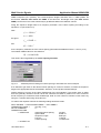
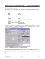
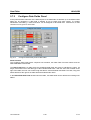
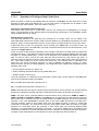
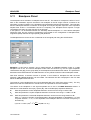
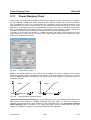
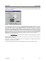
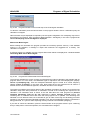
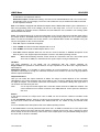
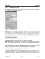
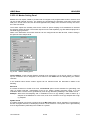
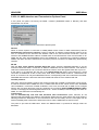
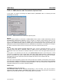
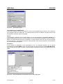
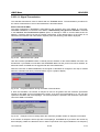
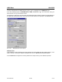
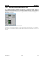
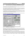
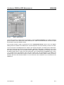
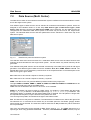
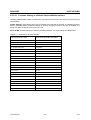
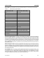
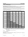
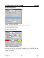
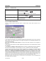
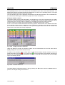
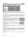
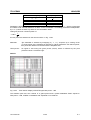
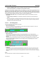
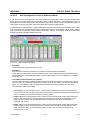
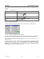
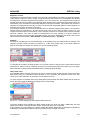
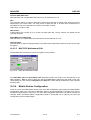
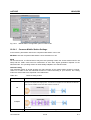
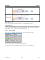
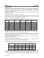
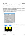
Carrier Settings Panel
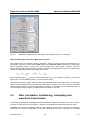
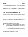
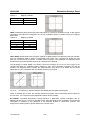
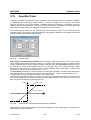
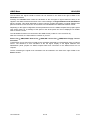
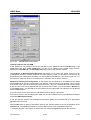
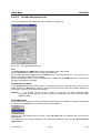
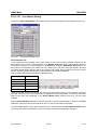
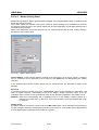
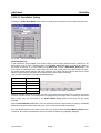
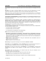
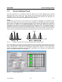
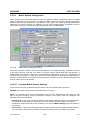
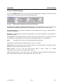
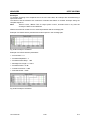
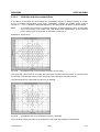
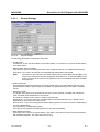
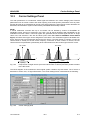
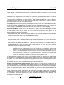
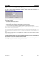
Power: In this field, a value can be assigned to each carrier to amplify the carrier power in comparison
to the others. A value in the range -80 dB to 0 dB can be set. This parameter is only effective when the
State is set to ON.
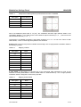
Modulation: In this field it is decided whether the carrier is modulated (ON) or not (OFF). In the OFF
state a pure CW carrier is displayed. With ON selected, the whole single-carrier scenario set in the
block diagram is calculated for this carrier. This parameter is only effective when State is set to ON.
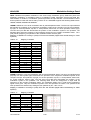
Data: One of the four data sources (Data 0, Data 1, Data 2, PRBS) configured in the Data Source panel
can be assigned to any carrier for which State ON has been selected and which is modulated. If the
same data source is used for all carriers, the respective data type is displayed in the status line of the
main panel. If different data sources are used, Various is displayed in the status line. If all carriers are
unmodulated or switched off, Not used is displayed.
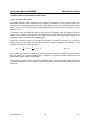
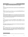
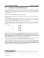
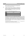
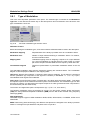
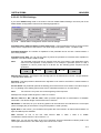
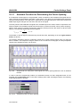
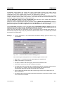
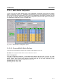
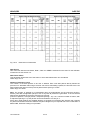
Initial Phase: In this field, the start phase of the channel can be freely selected in the range from 0° to
360°. The Phase Step parameter is used for easy configuration of several channels with equidistant
start phase. Thus it is possible, for instance, to generate five channels which are to have the start
phases 10°, 35°, 60°, 85° and 110° by setting Channel 0, Stop Channel 4, Initial Phase 10° and Phase
Step 25° and subsequently pressing the Accept button. You may use the start phase parameter to
generate your own optimized scenarios for minimizing the crest factor . If the Minimize Crest Factor
option is active, the set start phases are not effective and are dimmed in the table.
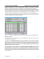
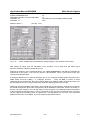
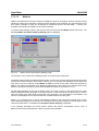
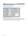
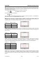
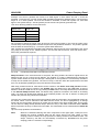
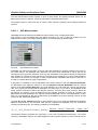
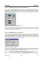
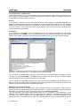
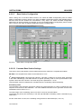
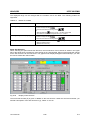
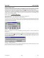
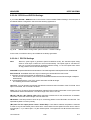
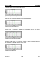
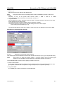
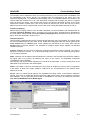
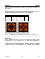
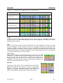
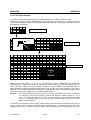
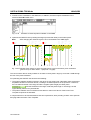
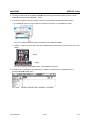
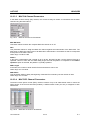
A carrier can be selected with the aid of the mouse in the table in the lower window of the panel. The
selected carrier is marked by an orange frame and transferred to the Channel Definition window where it
can be modified.
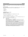
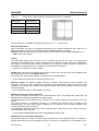
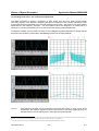
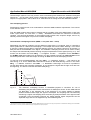
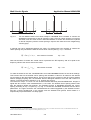
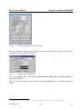
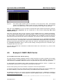
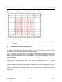
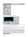
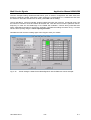
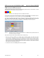
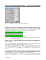
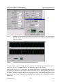
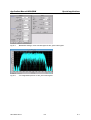
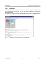
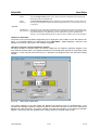
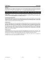
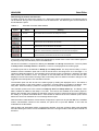
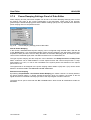
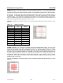
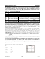
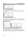
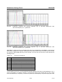
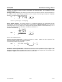
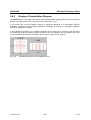
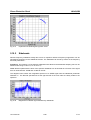
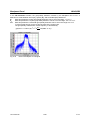
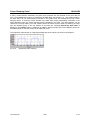
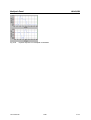
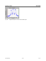
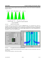
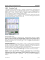
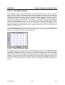
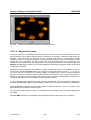
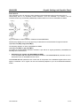
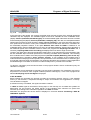
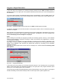
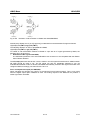
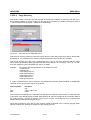
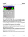
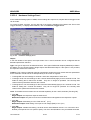
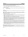
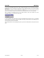
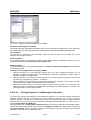
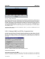
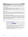
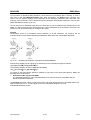
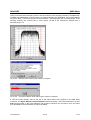
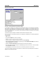
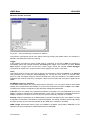
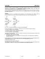
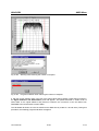
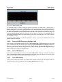
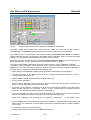
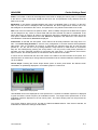
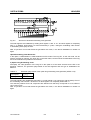
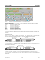
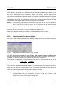
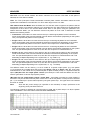
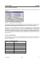
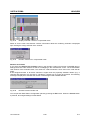
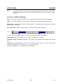
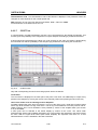
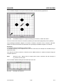
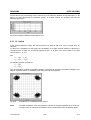
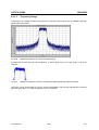
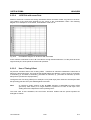
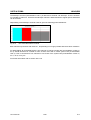
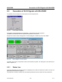
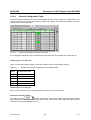
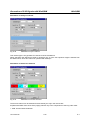
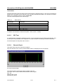
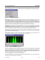
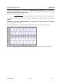
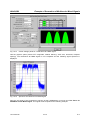
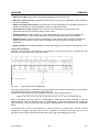
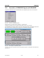
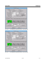
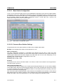
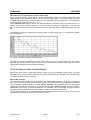
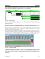
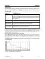
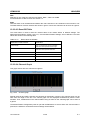
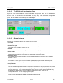
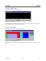
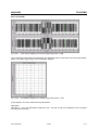
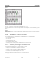
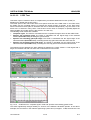
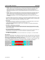
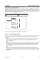
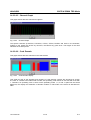
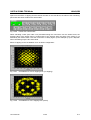
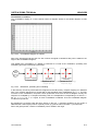
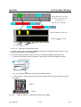
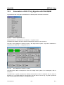
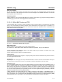
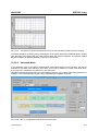
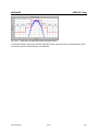
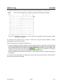
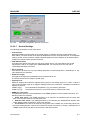
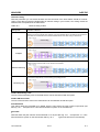
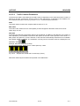
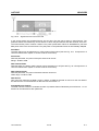
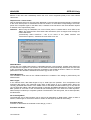
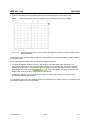
Carrier Graph: Pressing the Carrier Graph button opens an action panel where the defined carrier
constellation is qualitatively displayed in a scrollable graph on a carrier axis.
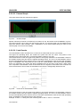
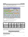
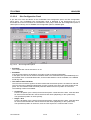
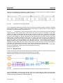
Fig. 7-6
Multicarrier Graph panel
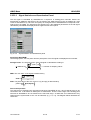
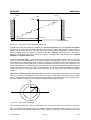
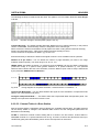
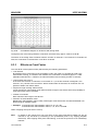
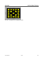
Unmodulated carriers are displayed as a red spectral line. A symbolic modulation spectrum is displayed
in green around the carrier frequency for modulated carriers. The height of the spectral lines or of the
modulation spectrum depends on the set carrier power. The Carrier Graph panel can be quit with the
Close button.
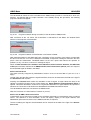
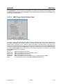
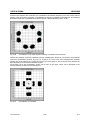
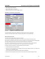
The Carrier Settings panel can be quit with the OK and Cancel buttons. With Cancel selected, all
modifications made to the settings are discarded.
1013.1642.02
7-7
E-1