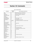
1
Fadal
Maintenance Manual
Section 04: Machine Maintenance
Scheduled
Maintenance
Maintenance &
Lubrication
Schedule
Daily
1) Check air pressure: Right regulator 120 PSI. max. (Tool Out Only). Left
Regulator 80-90 PSI.
2) Check way lube level. Use Castrol Magna BD68, Shell Tonna 68V or Mobil
Vactra #2 ONLY. (Not applicable to TRM)
3) Check way lube system for adequate oil flow to all way surfaces.
4) With tool in spindle blow chips from around A.T.C. and slide. NEVER blow
chips from around these areas during automatic tool change or without a
tool in the spindle.
5) Remove heavy chip build up from guards and way covers.
6) Wash A.T.C. and machine work area.
7) Check coolant level. (Not applicable to TRM)
8) Clean coolant screen. (Not applicable to TRM)
9) Clean the area around the machine.
10) Immediately clean any spills in the area.
Weekly
1) Check spindle cooler pump and refrigeration unit for proper operation. (Not
applicable to TRM)
2) Check fluid level of chiller tank and refill, if needed, with a 50/50 mix of
Dowfrost clear and de-ionized water. If de-ionized water is not available,
sodium-free distilled water can be substituted. Do not accept any
substitutes for DOWFROST CLEAR! (Not applicable to TRM)
3) Clean A.T.C. slide. (Not applicable to TRM)
4) Check air regulator.
March 2003
Section 04: Machine Maintenance
79
Fadal
Maintenance Manual
5) Drain and clean water separator.
6) Fill oiler if needed. (Not applicable to TRM)
7) Activate Thru-Tool coolant system for 2-3 minutes (if machine has this
option). (Not applicable to TRM)
8) Lubricate Y axis telescoping ball screw cover with way lube. (Not applicable
to TRM)
9) Grease axis way cover using molygraph.(Not applicable to TRM)
10) Grease retention rings using molygraph. (Not applicable to TRM)
11) Grease Geneva wheel and gear using Kopr-Kote. (Not applicable to TRM)
12) For high torque machines, check fluid level in the hydraulic actuator
reservoir. Refill, if needed, with Mobil DTE Heavy Medium.
13) Inspect all cooling fans, clean screens if necessary.
Every 4 months
Service way lube filter. Machines with an external filter require less frequent
replacement; however, do not exceed 4 months. When replacing the external
filter, fill the new filter with way lube prior to installation.
EMC & TRM
Lubrication of the
ballscrews
Every 6 months
To keep the EMC & TRM running smoothly, it is crucial that the ballscrews are
lubricated with MOBIL SHC #32 grease at least every 6 months depending on
use. Fadal recommends that a Fadal certified service person lubricate the
ballscrews.
1) Remove the way axis covers.
2) Locate the ZERK fittings on the ballscrew ballnut.
3) Insert the hose of the grease gun (TLC-0285) onto the ZERK fitting.
4) Pump MOBIL SHC #32 grease (CHM-0083) into each ballscrew ballnut.
Pump until grease begins to come out of the ballscrew ballnut.
5) Remove the grease gun.
6) RE-install the axis covers.
TRM Lubrication of
the Ways
Every 3 months
To keep the TRM running smoothly, it is crucial that the ways are lubricated with
bearing grease at least every 3 months depending on use.
1) Locate the ZERK fittings on the ways on the linear way truck.
80
Section 04: Machine Maintenance
March 2003
Fadal
Maintenance Manual
2) Insert the hose of the grease gun (TLC-0285) onto the ZERK fitting.
3) Pump MOBIL SHC #32 grease (CHM-0083) into each linear way truck.
Pump until grease begins to come out of the linear way truck.
4) Remove the grease gun.
Lubrication of the
Ways
Waylube System
USE WAYLUBE TYPE Castrol Magna BD68, Shell Tonna 68V or Mobil Vactra Oil
#2.
The Positive Displacement Injection (PDI) lube system is a solenoid-controlled
pneumatic system. When the solenoid is activated, the pump sends oil to the
junction block assemblies, which may contain several different size valves, at a
pressure ratio of 5:1. The pump is activated for 10 seconds, within a 4 minute
cycle, during which oil is distributed to all of the valves on the junction block
assemblies. When the solenoid is deactivated the oil flow stops and creates
back pressure which escapes through a relief valve. When the pressure on the
valve drops below 50 psi, a spring inside the valve is then able to inject oil into
the lines.
The CNC has direct control of the automatic lube system. The cycle is activated
by executing an axis motion in a CNC program, commanding an axis move in
MDI mode or pressing the JOG key. Once activated it monitors the oil level to
be sure the reservoir is above the minimum level. In addition, it shuts the oil
system down if the machine sits idle longer than one cycle of the lube system.
Frequently clogging filters indicate that the wrong waylube is being used. Use
Castrol Magna BD68, Shell Tonna 68V or Mobil Vactra Oil #2 ONLY.
Procedure for Flushing a Contaminated Waylube System
This procedure is necessary when the waylube that was being used in the
machine was incorrect. Other waylubes may contain paraffin wax or silicone.
1) Replace the 10-port way lube junction block that is located at the left side
of the saddle.
2) Replace the External filter on the BIJUR PDI way lube pump (Part # LUB0049).
3) Remove the oil line that is between the way lube pump and the three port
junction T that is located near the pump mount.
4) Verify that the flush pump air regulator is fully counterclockwise.
5) Attach an air line to the flush pump.
March 2003
Section 04: Machine Maintenance
81
Fadal
Maintenance Manual
!
WARNING
Verify that the air regulator is closed.
6) Insert the 3/8" hose from the flush pump into a container of grade A
kerosene.
7) Slowly open the air regulator clockwise to start the flush pump.
8) Increase the air pressure being careful that the output pressure does not
exceed 180 PSI at the gauge.
9) The pump is 4:1 ratio, 45 PSI input air pressure is 180 PSI output.
10) Enter a program that will exercise all axes to their limits. Start the program
running.
11) The flow of kerosene through the way lube system should be steady.
12) If the kerosene is dripping slowly down the column from underneath the Z
axis head the manifold filters are probably clogged. Replace the 8 port
junction block located on the Z axis head. Start over at step D.
13) Remove the 3/8" hose from the kerosene and place the hose in a can of
clean fresh waylube.
14) Slowly open the regulator clockwise on the flush pump. Pump waylube
through the lines until the system is well lubricated.
15) Stop the machine and return it to the COLD START position.
16) Turn the flush pump air regulator fully counterclockwise and remove the air
line.
17) Remove the flush pump and reattach the oil line from the Bijur pump to the
3 port junction.
Cooling Fans
!
WARNING
Power off the machine at the main disconnect switch and lockout/tagout
the main disconnect.
There are numerous cooling fans on the VMC that require periodic inspection.
Located in the CNC box and the junction box.
!
82
WARNING
Wear safety glasses!
Section 04: Machine Maintenance
March 2003
Fadal
Maintenance Manual
If the fan is turning slowly or not at all it may require cleaning or replacement.
The fan on the bottom of the junction box has a screen that requires periodic
inspection and removal for cleaning.
Spindle & Ballscrew
Cooling System
The spindle and ballscrew cooling system is made up of a motor pump
assembly, ambient-liquid temperature sensor assembly and a DP5P chiller. As
long as there is power to the machine the chiller pump is circulating Dowfrost
through the system. The ambient sensor is used to measure casting/air
temperature and the liquid sensor to measure Dowfrost temperature in the
return line. When there is a one degree temperature differential between the
two sensors the chiller is then powered on.
Pump Filter
There is a small filter and pressure gauge located on the pump head assembly.
Normal pressure is 3-5 pounds, cooled ball screws are 10 to 30 pounds. If the
pressure gauge shows a pressure above normal the filter should be inspected
and cleaned.
Figure 4-1 Pump Filter
Tank Reservoir
March 2003
The tank reservoir is located next to the motor pump assembly in the chiller
cabinet. The tank has a 2 1/2 gallon capacity. Visually check the fluid level with
the machine powered on. If the fluid level is less than 1/2 of the tank, mix the
Section 04: Machine Maintenance
83
Fadal
Maintenance Manual
Dowfrost to a 50:50 solution, with deionized water, or sodium free distilled
water and fill to no more than 3/4 full.
Figure 4-2 Tank Reservoir
Source for Dowfrost:
GOLDENWEST LUBRICANTS
1816 POTRERO AVE.
SOUTH EL MONTE, CA 91733
(626) 443 - 3441
(800) 540 - 5823
Do not accept any substitutes for DOWFROST!
Pressure
The cooling system should maintain a constant pressure of 3 to 5 psi on
machines with 400 I.P.M. rapid or 10 to 30 psi with 700 I.P.M. rapid.
If the pressure rises, the following conditions may exist:
• clogged pump filter;
• pinched oil lines;
• clogged cross tubes (only on 400 I.P.M. machines equipped with
cooled ball screws).
If the machine is losing pressure and the Dowfrost level keeps dropping, the
following conditions may exist:
• the O-ring that seals the ball screw cross tubes is leaking;
• there is a hole in one of the lines.
84
Section 04: Machine Maintenance
March 2003
Fadal
Maintenance Manual
Fuses, Heaters, &
Relays
Fluids
SEE SECTION 18: Fuses, Heaters, Parameters
Table 1: Fluids
RESERVOIR
FILL WITH
Waylube
CASTROL MAGNA BD68
SHELL TONNA 68V
or MOBIL VACTRA #2
Spindle Cooling System
DOWFROST CLEAR
(Mixed 50/50 with de-ionized water or sodium
free distilled water)
Auger
Rotary Tables
MOBIL GEAR 626
Hydraulic Hi/Low
MOBIL DTE HEAVY MEDIUM
Hydraulic Brake
HYDRAULIC OIL 32
Cleaning and Freeing Chips from the Auger Chip Removal System
Prior to cleaning or removing jammed material from the Auger or its exit tube.
1) Shut down the VMC by disconnecting the main switch in the back. It is
imperative to use OSHA approved Lock Out – Tag Out procedures to power
down the VMC.
Figure 4-3 Lock Out-Tag Out
!
March 2003
WARNING
Chips from the machining process are extremely sharp. Do not attempt to
remove these materials with bare hands.
Section 04: Machine Maintenance
85
Fadal
Maintenance Manual
!
WARNING
Do not remove material while the machine is operating or in the Emergency
Stop mode.
Chip Removal from the Machine Interior
Remove the side panels, open front doors, and remove the material from the
Auger. Wear heavy leather gloves and use a tool, such as pliers, when
removing material between the sheet metal and the auger.
Do not climb inside the machine to clean the auger. As shown below, all
portions of the auger are easily accessible from the front and side panel doors.
Figure 4-4 Auger Accessibility from Front and Side Panel Doors
Chip Removal from the Exit Tube
1) Removal of the tube may be necessary for material jammed in the exit
tube.
86
Section 04: Machine Maintenance
March 2003
Fadal
Maintenance Manual
2) Remove 6 hex bolts and washers from auger exit tube connection to the
sheetmetal housing.
Figure 4-5 Remove Hex Bolts and Washers from Auger Exit Tube
3) Wear heavy leather gloves and use a tool such as pliers when removing
jammed material from the auger exit tube. Remove using a heavy steel rod
(for hard to reach area in the mid-section of the tube) or pliers.
4) Reattach the auger exit tube to the sheet metal housing.
Dual Arm Tool
Changer
The causes of abnormal wear and fractures will be apparent when the tool
changer is used without lubricant. It is very important to grease all moving
parts of the tool changer at least once a week.
Lubricant
The lubricant should be changed annually, or when it has become visibly
deteriorated. The recommended lubricant is SAE 90-140, approximately 1.3
gallons.
Grease
Grease should be spread once a week in the following locations:
1) The claws of the tool changing arm unit.
2) The tip of the release pin of the tool changing arm unit.
Cleaning
1) Remove the chip powder from around the proximity switch inducing box.
2) Remove the chip powder from around the inverted moving body of the tool
pot.
3) The tool changing mechanism must be cleaned frequently to prevent
excess build up of chip powder.
March 2003
Section 04: Machine Maintenance
87
Fadal
Maintenance Manual
Inspection
Check the parts of the tool falling mechanism regularly and, check for grease
on the sliding base of the tool falling mechanism and the sliding base of the
pull rod. Check the parts of the tool pots and tool discs for tightness and overall
condition.
Scheduled
Maintenance
for Dual Arm Tool
Changer
The maintenance schedule is based on machine usage of eight hours a day,
five days a week.
Daily Maintenance
Perform the following daily:
1) Cleaning
a. Remove the chips and debris surrounding the proximity switch
inducing block.
b. Remove the chips and debris that have accumulated on the
inverted moving body of the tool pot.
c. Clear the tool changing mechanism of all debris before any operation.
2) Inspection:
a. Check the parts of the tool falling mechanism for damage and
wear. Add grease to the sliding base of the tool falling mechanism
and the pull rod.
b. Check the parts of the tool pots, tool discs, and snap rings for
damage and tightness.
Weekly Maintenance
Perform the following weekly:
1) Greasing:
a. Grease the claws of the tool changing arm unit.
b. Grease the tip of the release pin of the tool changing unit.
Miscellaneous Maintenance
Perform the following as necessary:
Change the lubricant annually or as needed. The recommended lubricant is
SAE 90-140. The Dual Arm Tool Changer uses approximately 5 liters (1.3
gallons).
88
Section 04: Machine Maintenance
March 2003
Fadal
Calibration of VMCs
using the Renishaw
laser
Scope
Reference
Documentation
Materials and
Equipment
Safety and
Environmental
Maintenance Manual
This qualification procedure applies to all Fadal VMCs calibrated using the
Renishaw Laser and software.
Renishaw Laser Measurement System – Current Version – User Manual
•
•
•
•
•
•
•
PC Loaded with Renishaw Software and PC10 Plug-in card.
Renishaw ML10 Laser
Renishaw Interferometer
Renishaw Reflector
Temperature Sensor ‘Magnetic’
Temperature Sensor ‘Mechanical’
Laser Tripod
Always use caution when working around machinery. Wear proper protective
clothing and wear safety glasses at all times.
Although the laser used for this measurement is safe to use, it is never a good
idea to look at a “Laser beam” with an unprotected eye. Take care to avoid an
unmanaged or unshielded beam, which could strike a bystander.
Definitions
Laser Calibration process – The process of obtaining deviations from a
standard and using these values to correct a standard via software.
Calibration Measurement – the final calibration measurement after the survey
compensation data has been entered into the controller. This is verification that
the survey compensation data has corrected the axis to the laser standard.
Survey – Laser measurement to obtain deviation data “to survey” which will be
used to enter compensation values into the controller.
Responsibilities
Fadal Machining Centers and Quality have responsibility for the test procedure.
Managers and Supervisors have responsibility for following this test procedure
where its use is required.
Procedure
This procedure will measure unidirectional axis travel in reference to a
calibrated laser. Deviations are generated which are loaded into the VMC
controller software. The software will correct for the mechanical deviations
improving the accuracy of axis travel. This procedure is designed as a
production qualification and machine calibration procedure. It covers only one
type of laser measurement. Refer to the current Renishaw manual for other
March 2003
Section 04: Machine Maintenance
89
Fadal
Maintenance Manual
laser methods if required. It may be used for re-calibration of a machine after
service or re-build. It may also be used for re-calibration of a machine after
service or re-build
The procedure is written for a technician that has had training both with the
Renishaw manual and on the job… Therefore, only trained technicians should
be performing this calibration procedure.
For further detail on Laser set-up, refer to the set-up section of the current
Renishaw manual.
CAUTION:
Standard Fadal
Cnc88hs
Laser could cause severe eye damage, do not point laser outside or mirror
range nor look directly into.
Axis to be Calibrated and Configuration
There are three axis (X, Y and Z) which may be calibrated using this procedure
and two configurations one using the motor encoder the other using the
optional scale box. The table below directs which axis and configuration to use
during production testing:
Survey at Encoder
No Scale Option
X/Y Scale Option
Z Scale Option
X Y Z*
XY
XYZ
XY
XYZ
Survey with Scale
Calibrate with Encoder
Calibrate with Scale
XY
XY
XYZ
XY
XYZ
* ONLY if Z-Calibrate Option is ordered.
The reason both Encoder and Scale calibration measurements are completed,
when the scale option is purchased, is to provide a backup calibration to the
customer in the event the scales need to be disabled.
Documentation
90
Place copies of all axis surveys and calibrations in the Fadal Machine Assembly
Checkout Record.
Place copies of the final axis surveys in customer documentation pocket of the
VMC.
Section 04: Machine Maintenance
March 2003
Fadal
Calibration
Requirements and
Limits
Maintenance Manual
VMCs over compensated via software...this is not considered calibrated. The
limits for proper calibration are (100%pas).
Maximum Target to Target Compensation < 0.0003”
Maximum Range of Compensation (Max delta from lowest value to highest) <
See Table Below.
VMC Model
X
Y
TRM
15
30
EMC
15
30
15, 15XT
15
10
2216, 2016L, 3016L
15
10
4020, 4020S
20
10
4020A
30
10
5020A
40
10
6030
50
20
8030
110
20
3020
20
10
4525
50
20
6535
110
20
X and Y values above are Compensation Values they represent 0.0001” units.
Laser Setup
To perform a VMC calibration the VMC must be in good working order and have
the table free of fixtures and parts.
•
•
•
•
•
•
•
CAUTION:
March 2003
With the machine powered up and in HOME position clear out old survey data.
Set up and level out the tripod so that the leveling bubble is in the middle of the target circle on the tripod legs at their base, set laser on the
tripod.
The front two feet on the bottom of the laser fit into the two holes on the
top of the tripod.
Aim the laser towards the middle T-slot of the machine.
Plug the laser cable into the small port on the back of the laser unit.
Plug the power cord into the back of the laser unit and plug in the computer power source.
Power on the computer and the laser.
Laser could cause severe eye damage, do not point laser outside of mirror
range, nor look directly into beam.
Section 04: Machine Maintenance
91
Fadal
Maintenance Manual
Note: The laser will require 15 minutes to warm up.
92
•
Plug the RS232 cable into the RS232 serial port on the back of the side
wiring cabinet of the VMC.
•
Plug the laser cable into the small port on the back of the laser unit.
Section 04: Machine Maintenance
March 2003
Fadal
Maintenance Manual
•
Install beam splitter into spindle. There are two arrows on the beam
splitter for calibrating the X–axis, the arrows should be pointing down
the X-axis and away from the column. The mirror “must be attached” to
the front of the beam splitter. For calibrating the Y-axis, the arrows go in
the same direction as the X-axis, but attach the mirror to the left of the
beam splitter.
•
Install mirror unit in the middle T-slot on the table.
•
Jog Z-axis head down so the bottom of the beam splitter and the mirror
on the table are horizontally even.
•
Tighten down the mirror on the table.
•
Install the first temperature sensor on the inside of the door away from
any draft, the second sensor, which is a magnetic temperature sensor
is to be placed in the middle T- Slot, middle of the table.
•
When lining up the laser beam the beam must go into the beam splitter
from the laser at 3:00 and come out of the splitter at 9:00 for X-axis.
•
With the X-axis at its negative end, line up the beams superimposed on
each other. Do this by jogging the head and adjusting the mirrors from
side to side. Be sure that the mirror and the beam splitter are completely parallel with each other.
•
Once the beams superimpose, jog the X-axis to its positive limit.
•
Line up the beams on the target of the laser superimposed. (This may
take a while with a lot of adjusting.)
•
Use the three adjusters to correct the lasers position, always level first,
then rotate (unit turning CW or CCW), and last translate (laser up and
down). This is the proper way for fast and accurate alignment of the
laser.
•
Once the beams superimpose, then turn the dial on the front of the
laser one turn in the clockwise direction. This should leave the target
position to open, to let the laser receive the beam.
•
After laser set up check the computer screen to see if the signal meter
is completely green, if so then you are ready to go. (If the signal meter
is not green, then adjust using steps above).
Aligning the laser
March 2003
Section 04: Machine Maintenance
93
Fadal
Download Survey
Maintenance Manual
For Fadal Control use the following survey downloading procedure:
§
Run Survey Download off computer desktop [REN2FAD.EXE]
§
On Fadal Control and at Enter Next Command, type CD,6
§
Follow program instructions and enter appropriate data.
Note: Program will move into axis calibration.
Axis Calibration
Data Capture
Target Sequence – Linear
Number of runs – 1 for survey 2 for calibration
Select Direction – Unidirectional
Amend Title Information – (Do as Prompted)
VMC Type
Serial Number
Location – (Same as “Auto Target Generate” Target)
Title – Encoder or Scale, and Survey or Calibration
Escape
ALT P = Changes the Datum
F2 = Datum’s the Laser
Alt – = Changes the sign from negative to positive and vice versa.
Run program on CPU
Select axis (x, y, or z)
Select length of axis
Agree or disagree
Push F2 to datum the computer
Start Data Capture
Push Auto and run the rest of the program on the VMC
When prompted, hit enter and slidehold the program – SETCS and send axis to
home position
Save data – Save and Name Computer files as follows:
[Axis] [E,S or C] [The last 6 serial number digits]
E = Encoder Survey, S = Scale Survey, C = Calibration Axis = X, Y
or Z
For a SN: 01200010111, an example is: XE010111 or YS010111
94
Section 04: Machine Maintenance
March 2003
Fadal
Maintenance Manual
Analyze
Surveys – (Error Comp Table)
Absolute Value
Produce Error Comp Table
Graph – (Renishaw Analysis)
Copies of survey and calibration placed in machine (electrical cabinet pocket)
and document book or jacket.
Exit Application
March 2003
Section 04: Machine Maintenance
95
Fadal
Sample output from
a laser measurement
system.
Maintenance Manual
RENISHAW CALIBRATION INTERFEROMETER SYSTEM
ERROR COMPENSATION TABLE
MACHINE VMC 3020
DATE: XXXXX
Axis: Y AXIS
Title: Type
value
Compensation type
Compensation resolution
Reference position
Compensation start
Compensation end
Compensation spacing
SERIAL No: XXXX
By:
Location: –9
Combined table with backlash
Absolute
0.0001 in
–9.0000 in
–9.0000 in
10.0000 in
1.0000 in
Backlash value
No.
Axis position
(in)
1
2
3
4
5
6
7
8
9
10
11
12
13
14
15
16
17
18
19
20
96
–9.00000
–8.00000
–7.00000
–6.00000
–5.00000
–4.00000
–3.00000
–2.00000
–1.00000
0.00000
1.00000
2.00000
3.00000
4.00000
5.00000
6.00000
7.00000
8.00000
9.00000
10.00000
Section 04: Machine Maintenance
0.0000 in
Compensation values
Combined
(0.0001 in)
0
–1
–2
–2
–3
–3
–4
–4
–4
–4
–4
–4
–4
–5
–4
–5
–5
–6
–6
–7
March 2003
Fadal
Maintenance Manual
This partial view of COMP_VALUES_y shows the survey values from the above
file. Notice that there are three pointers in the brackets. Out of those three, the
middle number has the same meaning as the position No. in the file above.
N50 $AA_ENC_COMP [_ENC_NR, 1, AX2] = - 0.0000 corresponds to No. 1
and N75 $AA_ENC_COMP [_ENC_NR, 6, AX2] = - 0.0003 corresponds to No.
6 in the table.
N75 $AA_ENC_COMP[_ENC_NR, 6, AX2] = - 0.0003
N35 $MA_ENC_COMP_ENABLE[_ENC_NR, AX2] =0
N40 NEWCONF
stopre
;-----BEGINNING—OF—SURVEY---------N45 $AA_ENC_COMP[_ENC_NR,0,AX2]=-0.0000
N50 $AA_ENC_COMP[_ENC_NR,1,AX2]=-0.0000
N55 $AA_ENC_COMP[_ENC_NR,2,AX2]=-0.0001
N60 $AA_ENC_COMP[_ENC_NR,3,AX2]=-0.0002
N65 $AA_ENC_COMP[_ENC_NR,4,AX2]=-0.0002
N70 $AA_ENC_COMP[_ENC_NR,5,AX2]=-0.0003
N75 $AA_ENC_COMP[_ENC_NR,6,AX2]=-0.0003
N80 $AA_ENC_COMP[_ENC_NR,7,AX2]=-0.0004
N85 $AA_ENC_COMP[_ENC_NR,8,AX2]=-0.0004
N90 $AA_ENC_COMP[_ENC_NR,9,AX2]=-0.0004
N95 $AA_ENC_COMP[_ENC_NR,10,AX2]=-0.0004
N100 $AA_ENC_COMP[_ENC_NR,11,AX2]=-0.0004
N105 $AA_ENC_COMP[_ENC_NR,12,AX2]=-0.0004
N110 $AA_ENC_COMP[_ENC_NR,13,AX2]=-0.0004
N115 $AA_ENC_COMP[_ENC_NR,14,AX2]=-0.0005
N120 $AA_ENC_COMP[_ENC_NR,15,AX2]=-0.0004
N125 $AA_ENC_COMP[_ENC_NR,16,AX2]=-0.0005
N130 $AA_ENC_COMP[_ENC_NR,17,AX2]=-0.0005
N135 $AA_ENC_COMP[_ENC_NR,18,AX2]=-0.0006
N140 $AA_ENC_COMP[_ENC_NR,19,AX2]=-0.0006
N145 $AA_ENC_COMP[_ENC_NR,20,AX2]=-0.0007
;-------END--OF--SURVEY---------------N150 $AA_ENC_COMP_STEP[_ENC_NR,AX2]=1
March 2003
Section 04: Machine Maintenance
97
Fadal
Laser Shut Down
Maintenance Manual
•
•
•
•
•
98
When finished with entire calibration procedure for all axes Press F5
and exit application, then exit to DOS.
Turn off laser and move dial one notch until target shows.
Unplug laser cable and RS232 cable.
Power down and Unplug computer.
Store all equipment and clean up workstation.
Section 04: Machine Maintenance
March 2003
Fadal
Pallet Changer/
Hydro Sweep™
Maintenance Manual
Each Part Cycle
1) Make certain that HydroSweep unit is cycled before every Pallet Exchange.
Use an M20 in the program to make it automatic. Frequent washing out of
chips prevents them from building up into difficult-to-remove piles.
2) Blow away any chips that may lodge underneath Pallet in Hydraulic Arm
groove.
Daily Maintenance
1) Put both Pallets away onto stand. Put tool in spindle. Wash down interior
with coolant hose nozzle, using care to keep splash away from Automatic
Tool Changer, Head assembly, or any wiring connections.
2) Wash out HydroSweep drum, clearing any chips from inside. Inspect
behind HydroSweep Ram for any stray chips blocking return slot.
3) Clean chips from trough behind Table and Saddle, and on Sliding Doors.
4) Guard, and inspect between front Y-axis way cover and front of machine for
chip buildup.
5) Remove screen/tank cover over fluid tank, and clean screen protecting
pumps.
6) Using tool, check for any chip buildup in tank ahead of screen.
7) Check tank reservoir fluid level, and refill as necessary.
8) Check Waylube level, refill with Castrol Magna BD68, Shell Tonna V68, or
Mobil Vactra #2.
9) Check for air pressure. Single regulators should be set for 80PSI. Dual
regulators should be set at 80PSI on the left gauge, and 90-100PSI
maximum on the right gauge.
10) Move X-axis to either side, and flip over outer X-axis way cover. Inspect for
chip buildup, and clean. Check for waylube presence on both X-axis ways.
Inspect Z-axis and Y-axis as well.
11) Check pressures/vacuum on Coolant-Thru pump filter and replace filter, if
necessary.
Weekly Maintenance
1) Check Hydraulic Fluid level for Pallet Clamp on top of machine. Use Mobil
DTE Heavy Medium.
2) Remove Hydraulic Arm pump cover, and inspect Hydraulic Arm system,
refilling fluid if necessary.
March 2003
Section 04: Machine Maintenance
99
Fadal
Maintenance Manual
3) Check Hydraulic Arm chain tension by push/pull on arm.
4) Remove Head Cover, and inspect fluid lines for Hi/Lo Idler assembly,
refilling, if necessary.
5) Remove all tools from tool changer, and clean out any chip buildup. When
returning tools to ATC, inspect retention ring tension on tool holders for
excessive looseness, replacing rings, if necessary.
6) Disconnect front Y-axis way cover from saddle, and check for chip buildup.
7) Inspect under Y-axis motor for chips, and clear out drain ports under Y-axis
ways nearest the column.
Monthly Maintenance
1) Carefully remove pallets, and grease rail bearings, using care not to
damage lip seals.
2) Remove spindle motor top filter cover, and inspect filter. Replace, if
necessary.
3) Inspect Pallet Roller latch system for both Pallets on stand.
4) Inspect all HydroSweep nozzles for chip clogging.
5) Check Pallet Lift Door for smooth operation.
6) Inspect Chiller cabinet for low fluid in container, should be 1/2 to 3/4 full.
7) Inspect Chiller recirculation pump filter, and clean as needed.
8) Blow air into top of Chiller louvers to clear out dirt collecting on condenser.
9) At bottom of rear cabinet, remove fan filter screen and clean.
10) Inspect front door rollers, tightening as necessary.
11) Check door interlock system for proper operation.
12) Remove head cover and inspect belts, and check for any Coolant-thru
system leaks.
13) Inspect all cables, hoses, and tubing for looseness, or damage.
100
Section 04: Machine Maintenance
March 2003
Fadal
HydroSweep™ Only
Maintenance Manual
Each Part Cycle
1) Make certain that HydroSweep unit is cycled before every part change, or
run at least 20 minutes per hour run time. Use an M20 in the program to
make it automatic. Frequent washing out of chips prevents them from
building up into difficult-to-remove piles, and clears drum from chip
buildup.
2) Clean away any chips that may lodge in rear trough at bottom of Y-axis
sliding tray.
Daily Maintenance
1) Wash down interior with coolant hose nozzle, using care to keep splash
away from Automatic Tool Changer, Head assembly, or any wiring
connections.
2) Wash out HydroSweep drum, clearing any chips from inside. Inspect
behind HydroSweep Ram for any stray chips blocking return slot.
3) Clean chips from trough behind Table and Saddle, and on Sliding Guard,
and behind Sliding Guard near Y-axis ballscrew, and inspect between front
Y-axis way cover and front of machine for chip buildup.
4) Remove screen/tank cover over fluid tank, and clean screen protecting
pumps.
5) Using shovel, check for any chip buildup in tank ahead of screen.
6) Check tank reservoir fluid level, and refill as necessary, using only coolant
with anti-foam inhibitors.
7) Check Waylube level, refill with Castrol Magna BD68, Shell Tonna V68, or
Mobil Vactra #2.
8) Check for air pressure. Single regulators should be set for 80PSI. Dual
regulators should be set at 80PSI on the left gauge, and 90-100PSI
maximum on the right gauge.
9) Move X-axis to either side, and flip over outer X-axis way cover. Inspect for
chip buildup, and clean. Check for waylube presence on both X-axis ways.
Inspect Z-axis and Y-axis as well.
10) Check pressures/vacuum on Coolant-Thru pump filter and replace filter, if
necessary.
March 2003
Section 04: Machine Maintenance
101
Fadal
Maintenance Manual
Weekly Maintenance
1) Remove Head Cover, and inspect fluid lines for Hi/Lo Idler assembly,
refilling, if necessary.
2) Remove all tools from tool changer, and clean out any chip buildup found.
When returning tools to ATC, inspect retention ring tension on tool holders
for excessive looseness, replacing rings, if necessary.
3) Disconnect front Y-axis way cover from saddle, and check for chip buildup.
4) Inspect under Y-axis motor for chips, and clear out drain ports under Y-axis
ways nearest the column.
Monthly Maintenance
1) Remove spindle motor top filter cover, and inspect filter. Replace, if
necessary.
2) Inspect all HydroSweep nozzles for chip clogging.
3) Inspect Chiller cabinet for low fluid in container, should be 1/2 to 3/4 full.
4) Inspect Chiller recirculation pump filter, and clean as needed.
5) Blow air into top of Chiller louvers to clear out dirt collecting on condenser.
6) At bottom of rear cabinet, remove fan filter screen and clean.
7) Inspect front door rollers, tightening as necessary.
8) Check door interlock system for proper operation.
9) Remove head cover and inspect belts, and check for any Coolant-thru
system leaks.
10) Inspect all cables, hoses, and tubing for looseness, or damage.
The above maintenance procedures may be performed by customer's
maintenance crew.
6-Month Planned Maintenance
This should be performed by the Fadal Planned Maintenance Crew semiannually.
102
Section 04: Machine Maintenance
March 2003
Fadal
Tests for CE
Safeguards on Fadal
Machines
Maintenance Manual
These tests should be done when machine is first installed and after servicing
when any components are replaced.
1) Power on machine but do not cold start.
Start spindle. (Press Shift-Spindle on)
• Spindle will not start OR
• Press Emergency Stop; spindle must stop.
• Immediately release Emergency Stop; spindle does not start.
2) Cold start machine.
Start spindle. (Press Shift-Spindle on)
• Press Emergency Stop; spindle must stop.
• Immediately release Emergency Stop; spindle shall not start, VMC
remains in emergency stop.
• Repeat test in Auto, MDI, and Jog modes.
3) Start spindle. (Press Shift-Spindle on)
•
•
•
•
Open front door; spindle must stop.
Try to restart spindle; spindle does not start with doors open.
Check LED on 2000-1 board; it should be on.
Check contactor for spindle; contacts should be out. (There may be a 5
to 10 second delay between the opening of the door and the release of
the contactor. This allows a controlled stop).
4) Close doors.
•
•
Repeat test with left side panel.
Repeat test with right side panel.
5) Do a TC,1 with doors open.
•
•
Z-axis does not rise if doors are open.
close doors and execute TC,1.
6) With doors open press manual (ending TC,1).
•
March 2003
Z-axis does not move unless doors are closed.
Section 04: Machine Maintenance
103
Fadal
Maintenance Manual
Daily & Weekly Safety Tests for CE Safety Circuits
To ensure proper functioning of safety circuits, the following tests should be
performed on a regular basis.
Daily
The Door Interlock Monitor will be on the 1310-0C board if the machine has an
auger, or on the 2000-1A board.
If the machine does not have an auger and is not CE, there will be no Door
Interlock Monitor.
Door Interlock Monitor Daily Test for 2000-1A or 1310-0C
1) Close all doors. Make sure VMC is not in emergency stop.
2) Start spindle at slow speed.
3) Open front door.
Spindle should stop immediately (fully stopped from any speed in less than
5 seconds). Five to ten seconds after the door is opened you should hear
the spindle contactor open. (The five to ten second delay allows the spindle
to come to a controlled stop.)
4) Close front door. Spindle contactor will immediately reenergize.
Daily
Front Door Lock Daily Test for 2030-OA
1) Close all doors. Make sure machine is not in emergency stop.
2) Open front door. You may be able to hear the spindle contactor open, if not
a second person will be needed to watch the contactor.
3) Close front door. You may be able to hear the contactor close, if not see 2
above.
4) Start spindle. Attempt to open front door. Front door should be locked.
5) Stop spindle. There should be a delay of 1 to 5 seconds after the spindle
comes to a complete stop before the door unlocks. (This delay can be
adjusted from 1 to 5 seconds with R22.)
6) In either automatic or manual mode command a tool change. Attempt to
open the door. Front door should be locked while turret is moving toward
spindle or while dual arm tool changer arm is in motion.
Dual Arm Tool Changer (1330) Daily Test
No daily test.
104
Section 04: Machine Maintenance
March 2003
Fadal
Maintenance Manual
Pallet Changer (1100-3A) Daily Test
No daily test.
Weekly
The Door Interlock Monitor will be on the 1310-0C board if the machine has an
auger, or on the 2000-1A board.
If the machine does not have an auger and is not CE, there will be no Door
Interlock Monitor.
Door Interlock Monitor (2000-1A) Weekly Test
1) Close all doors. Make sure VMC is not in emergency stop.
2) Open cabinet containing Door Interlock Board (2000-1A) and examine
LEDs and relays on the 2000-1A board.
•
•
•
•
Red door LEDs should be off.
Green door LEDs should be on.
Estop relay (K3) should be on (LED lit).
Output relay for spindle contactor (K2) should be on (LED lit).
3) Press Emergency Stop switch.
•
•
Estop relay should go off immediately.
Output relay should go off after 5 to 10 seconds.
4) Release Emergency Stop switch and clear emergency stop condition by
pressing Jog.
5) Open front door.
•
•
•
Front door red LED should be on.
Green door LEDs should be off.
Spindle contactor should release after 5 to 10 seconds.
6) Close front door and open left side door.
•
•
•
Left door red LED should be on.
Green door LEDs should be off.
Spindle contactor should release after 5 to 10 seconds.
7) Close left side door and open right side door.
•
•
•
March 2003
Right door red LED should be on.
Green door LEDs should be off.
Spindle contactor should release after 5 to 10 seconds.
Section 04: Machine Maintenance
105
Fadal
Maintenance Manual
Weekly
Door Interlock Monitor Weekly Test for 2000-1 B or -1 C
1) Close all doors. Make sure VMC is not in emergency stop.
2) Open cabinet containing Door Interlock Board (2000-1 B or -1 C) and
examine LEDs and relays on the 2000-1 B or -1 C board.
•
•
•
•
•
•
Red door LEDs should be off.
Yellow door LEDs should be off. Green "Doors Closed" LED should be
on.
Red Slidehold LEDs should be off.
Estop relay (K3) should be on (LED lit).
Green "Spindle Enable" LED should be on.
"Spindle" relay for spindle contactor (K2) should be on (LED lit).
3) Press Emergency Stop switch.
•
•
•
Estop relay should go off immediately.
Spindle Enable LED and Spindle relay should go off after 5 to 10 seconds.
Spindle contactor should then release.
4) Release Emergency Stop switch and clear emergency stop condition by
pressing Jog.
5) Open front door.
•
•
•
•
Front door red LEDs should be on.
Green "Doors Closed" LED should be off.
The yellow LED for the front door should flash at the instant the door is
opened.
Spindle Enable LED and Spindle relay should go off and Spindle contactor should release after 5 to 10 seconds.
6) Close front door and open left side door.
•
•
•
•
Left door red LEDs should be on.
Green "Doors Closed" LED should be off.
Yellow door LED should flash at the instant the one door is closed and
when the other door is opened.
Spindle Enable LED and Spindle relay should go off and Spindle contactor should release after 5 to 10 seconds.
7) Close left side door and open right side door.
•
106
Right door red LEDs should be on.
Section 04: Machine Maintenance
March 2003
Fadal
Maintenance Manual
•
•
•
Green "Doors Closed" LED should be off.
Yellow door LED should flash at the instants the one door is closed and
when the other door is opened.
Spindle Enable LED and Spindle relay should go off and Spindle contactor should release after 5 to 10 seconds.
Door Interlock Monitor on Auger Board (1310-0C) Weekly Test
1) Close all doors. Make sure VMC is not in emergency stop.
2) Open cabinet containing Auger Board (1310-0A) and examine LEDs and
relays on the 1310-0A board.
•
•
•
•
•
Red door LEDs should be off.
Green door LEDs should be on.
Estop relay (K7) should be on (LED lit).
Spindle relay for spindle contactor (K5) should be on (LED lit).
Heart LED should be blinking.
3) Press Emergency Stop switch.
•
•
•
Estop relay should go off immediately.
Heart LED should be off.
Spindle relay should go off after 5 to 10 seconds.
4) Release Emergency Stop switch and clear emergency stop condition by
pressing Jog.
5) Open front door.
•
•
•
•
Front door red LED should be on.
Green door LEDs should be off.
Heart LED should be off.
Spindle contactor should release after 5 to 10 seconds.
6) Close front door and open left side door.
•
•
•
Left door red LED should be on.
Green door LEDs should be off.
Spindle contactor should release after 5 to 10 seconds.
7) Close left side door and open right side door.
•
•
•
•
March 2003
Right door red LED should be on.
Green door LEDs should be off.
Heart LED should be off.
Spindle contactor should release after 5 to 10 seconds.
Section 04: Machine Maintenance
107
Fadal
Maintenance Manual
Weekly:
Front Door Lock Weekly Test for 2030-OA
1) Close all doors.
2) Open cabinet containing Front Door Lock Board (2030-OA) and examine
LEDs and relays on the 2030-OA board.
•
•
•
•
•
Power LED should be on.
Green "Unlock Door" LED should be on.
Green "Doors Closed" LED should be on.
LED on K6 and K7 should be on.
No other LEDs should be on.
3) Open front door.
•
•
•
Green "Doors Closed" LED should be off.
LED on K7 should be off.
Other LEDs should be unchanged.
4) Close front door and start spindle.
•
•
•
•
•
Attempt to open front door.
Front door should be locked.
"Spindle Rotating", "Spindle ON", "VMC Motion", and "Unlock Delay"
LEDs should be on.
"Unlock Door" LED should be off.
LED on K6 should be off.
5) Stop SPINDLE.
•
There should be a delay of 1 to 5 seconds after the spindle comes to a
complete stop before the door unlocks.
6) If there is a pallet changer start a pallet change.
•
•
•
•
Attempt to open front door. Front door should be locked.
"Pallet Motion", "VMC Motion", and "Unlock Delay" LEDs should be on.
"Unlock LED should be off.
LED on K6 should be off.
Dual Arm Tool Changer (1330) Weekly Test
1) Make sure the VMC is not in emergency stop, that the spindle is off, and
that no tool change is in progress.
2) Open cabinet containing the Dual Arm Tool Changer Control Board 1330-0
and examine the LEDs and relays.
108
Section 04: Machine Maintenance
March 2003
Fadal
Maintenance Manual
•
•
•
•
•
The LED (D16) for the contactor SSR should be off.
The E-stop relay (K5) should be energized (LED on, contact indicator
showing).
The E-stop Signal relay (K6) should be energized (LED on, contact indicator showing).
The Drawbar and Arm Interlock relay (K7) should be energized (LED on,
contact indicator showing).
The Arm Power relay (K8) should be energized (LED on, contact indicator showing).
3) Start spindle and examine LEDs and relays on 1330-0.
•
•
The Drawbar and Arm Interlock relay (K7) should not be energized (LED
off, contact indicator not showing).
The Arm Power relay (K8) should not be energized (LED off, contact
indicator not showing).
4) Stop spindle. Press Emergency Stop. Examine LEDs on 1330-0.
•
•
•
The E-stop relay (K5) should not be energized (LED off, contact indicator not showing).
The Drawbar and Arm Interlock relay (K7) should not be energized (LED
off, contact indicator not showing).
The Arm Power relay (K8) should not be energized (LED off, contact
indicator not showing).
Pallet Changer (1100-3A) Weekly Test
1) Make sure there are no obstructions to the light curtain.
•
•
The green LED on the Light Curtain receiver should be on.
The red LED on the Light Curtain receiver should be off.
2) Break the light curtain path with your hand.
•
•
•
The green LED on the Light Curtain receiver should be off.
The red LED on the Light Curtain receiver should be on.
Red LEDs on the receiver will also show the beams that are being
obstructed.
3) Make sure there are no obstructions to the light curtain. Open the cabinet
containing Pallet Change Power Distribution board (1100-3A) and examine
the LEDs on the 1100-3A.
•
•
March 2003
The green LEDs (D8 and D9) on the 1100-3A board should be on.
The red LED (D7) on the 1100-3A board should be off.
Section 04: Machine Maintenance
109
Fadal
Maintenance Manual
4) Obstruct the light curtain (a towel over one of the mirrors will do this) and
observe the LEDs on the 1100-3A.
•
•
The green LEDs (D8 and D9) on the 1100-3A board will be off.
The red LED (D7) on the 1100-3A board will be on.
5) Start a pallet change and while the pallet is in motion obstruct the light
curtain. The pallet change should stop immediately and a message should
appear on the monitor requiring Start to be pressed to continue.
Zero-Out Memory
Procedure
Note: Everything in memory will be erased! Store desired programs &
data to disk
1) Send machine to COLD START:
• Type SETCS < ENTER >.
• Type HO <ENTER>.
• Press START.
2) Display and record the BACKLASH settings on the second page of this
instruction sheet (Settings) in the spaces provided:
• Type BL <ENTER>. Record the displayed values.
3) Display and record the PARAMETER settings on the second page of this
instruction sheet (Settings) in the spaces provided:
NOTE: Some parameters appear ONLY in Format 1 or in Format 2, but NOT IN
BOTH FORMATS.
• Type SETP <ENTER>. Record the displayed values.
• Type P <ENTER> to display the second page of settings. Record the displayed
values.
• Type P <ENTER> to display the third, page of settings. Record the displayed
values.
4) After all BACKLASH and PARAMETER settings have been recorded, zero
memory:
• Press <MANUAL> to get to ENTER NEXT COMMAND.
• Type DI < ENTER >.
110
Section 04: Machine Maintenance
March 2003
Fadal
Maintenance Manual
• Type GOA3000 <ENTER> to display the Diagnostics Menu.
• Press spacebar to get to Page 2 of the Diagnostic Menu, and select option 5 ZERO MEMORY.
• Answer "Y" (type Y) to both questions the control asks. Memory is reset.
NOTE: If you are replacing a module(s), now is the time to power down the
machine,
replace the module(s), and power up ---- then proceed directly to STEP 5
below.
• Select option 2 - START CNC. This will take the control back to ENTER NEXT
COMMAND.
5) Restore PARAMETER values as needed:
NOTE: The control will ask for BACKLASH values, but the PARAMETER values
must be checked first.
• Type SETP <ENTER> to check and, if needed, re-enter PARAMETER settings page 1.
• Type P <ENTER> to check and, if needed, re-enter PARAMETER settings page 2.
• Type P <ENTER> to check and, if needed, re-enter PARAMETER settings page 3.
6) Restore BACKLASH values:
• Power off the machine, wait 15 seconds, power on the machine, COLD
START.
• Enter the BACKLASH values previously recorded as follows:
for X axis
for Y axis
for Z axis
for A axis
for B axis
BL,1,value 1, value2, value3 < ENTER >
BL,2,valuel,value2,value3 <ENTER>
BL,3,value < ENTER >
BL,4,value <ENTER>
BL,S,value <ENTER>
7) Load the programs and offsets back into the machine. This procedure is
now complete.
March 2003
Section 04: Machine Maintenance
111
Fadal
Zero-Out Memory
Settings
Maintenance Manual
Last Home Position X___________ Y___________ Z____________
Backlash Settings
X-axis Backlash ___________ ,___________,___________
Y-axis Backlash ___________ ,___________,___________
Z-axis Backlash___________
A-axis Backlash___________
B-axis Backlash___________
Parameter Settings
Format:___________Baud Rate:__________Spindle After M6:_______
Axes:___________Travel:___________Pendant:___________
Default:___________A-AxisRatio:__________M60/A-Axis Brake:___________
Default:___________B-AxisRatio:___________M60B-AxisBrake:___________
Default:Tool Changer Cap:IMM Fixed Cycle:
RPM Factor:Spindle Type:Orientation Factor:
Parameter settings - Page 2
Default:___________M3:_______M7:_______3 Phase>5%Low:___________
Pu Format:__________N-words Ordered:__________Tool Table:___________
Crc Mode:___________Binary Buffers:___________High Torque:__________
Spindle Off:___________Turret Factor:___________CMD Menu:___________
Pallet:___________Gain:___________Ramp:___________
Aspect:___________Tilers:___________Overload:___________
Parameter Settings - Page 3
Screw:___________Imp:___________Xyz Ramp:___________
Z Tap Gain:___________Vector:___________Axis Display:___________
Auto Brake:___________A-pallet:___________ B-pallet:___________
5-Axis Head:___________G0 Detail:___________Feedback:___________
112
Section 04: Machine Maintenance
March 2003