1
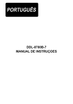
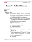
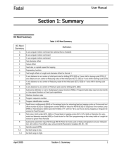
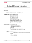
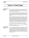
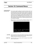
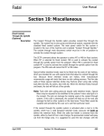
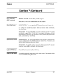
Fadal
User Manual
Section 15: Touch Probes
Touch Probes
Touch Probe Length Offset
The tool setting probe is used with the UTILITY command to establish the
length offset. It can also be used for tool breakage detection and setting tool
diameter offsets. The UTILITY command is used to set diameter and locate the
length offset. Enter the command UT and the following menu appears:
Figure 15-1 Utility Options Menu
Tool Setting Cycle
April 2003
The utility command provides two basic functions to aid in the setup procedure.
The first function steps the operator through the process of retrieving tools
from the turret, entering the diameters and locating the length offsets.
Section 15: Touch Probes
339
Fadal
User Manual
After selecting this cycle the CNC displays the following menu:
Figure 15-2 Tool Setting Cycle Menu
The information regarding the current tool in the spindle is displayed and the
CNC prompts the user for the starting tool number. After entering the first tool
number, the CNC responds with the message:
Figure 15-3 Starting Tool Number Prompt
Respond by entering the last tool number to be set.
340
Section 15: Touch Probes
April 2003
Fadal
User Manual
The following menu appears after the starting and ending tool numbers are
defined:
Figure 15-4 Tool Setting Options Menu
Option 1=Jog to
Position
This option is used for locating the tool length offset by using the JOG function
of the CNC. The CNC prompts the operator to press the JOG key and manually
move to the gauge point instead of the automatic process using the probe.
Option 2 & 3 - Probe
Mount
The CNC allows for two probe mounting positions. The left or right orientation is
defined as standing in front of the machine, looking Y+ direction.
LEFT
MOUNT
RIGHT
MOUNT
Y+
X+
Figure 15-5 Probe Mounting Positions
Selecting left or right mount determines the X axis shift direction when locating
the tool length of an end mill. The left mount probe shifts the X axis in the
positive direction before moving Z down. The right mount shifts the X axis in the
negative direction before moving Z down.
April 2003
Section 15: Touch Probes
341
Fadal
Probe Fixture Offset
Number
(0, 1-48)
User Manual
Once the probe is installed, a fixture offset can be dedicated to tool setting. The
X and Y fixture offset value is the location of the center of the tool setter stylus
relative to the HOME position.
X AMOUNT
Y AMOUNT
HOME
Figure 15-6 Probe Fixture Offset Number
Respond with 0 to ignore this feature or enter the fixture offset number.
Probe Offsets
Z Fixture Offsets
GAGE POINT
Z- AMOUNT
Z OFFSET
Figure 15-7 Z Fixture Offsets
342
Section 15: Touch Probes
April 2003
Fadal
User Manual
After selecting a fixture offset the CNC displays the current X, Y, and Z values
and prompts the user with the following message:
Figure 15-8 Z Fixture Offset Message
Respond by pressing the Y key and begin the process of establishing the Z
fixture offset. Then press the N key and the CNC continues the setup procedure
using the current Z value.
When a fixture offset is selected, the Z fixture offset value is subtracted from
the current touch position when determining the length offset. A positive value
increases and a negative value shortens the length offset.
After selecting a fixture offset, the CNC moves X and Y axes to the fixture offset,
loads the first tool, and begins the tool setting process by displaying the
following menu:
Figure 15-9 Tool Setting Options Menu
April 2003
Section 15: Touch Probes
343
Fadal
User Manual
If the program requires the diameter or the tool is an end mill, the operator
selects function 1 and enters the diameter. Select function 2 to begin locating
the length offset.
Locating Length
Using the JOG
Function
The CNC displays the message:
PRESS JOG AND MOVE TO HEIGHT BLOCK OR PRESS MANUAL TO EXIT
The operator then presses the JOG key and moves the tool to the desired offset
position. When the tool is at the desired location press the MANUAL key.
Locating Length
Using the Probe
Selecting function 2 causes the CNC to move the tool down in one of two ways:
1) If a diameter is entered, the X axis shifts the radius amount, spins the tool
backwards, then locates the length.
2) Specifying a zero tool diameter causes the CNC to move the Z down without
shifting the X axis or spinning the tool.
The CNC performs the following actions for locating the length of an end mill:
a.
b.
c.
d.
e.
f.
g.
h.
i.
344
Spindle ON reverse at 100 RPM
X axis is shifted the radius of the tool
Z axis down until initial touch
Z axis is raised .010"
Spindle speed is increased to 500 RPM
Z axis down until final touch
Spindle off, length offset is stored
Z axis returned to COLD START
X axis shift position returned
Section 15: Touch Probes
April 2003
Fadal
User Manual
After locating the length by either the JOG or PROBE method, the CNC
automatically performs a tool change to get the next tool and displays the
following menu:
Figure 15-10 Tool Setting Options Menu
The process is repeated until the last tool has been set.
Tool Breakage
Detection
Tool breakage detection is achieved by a two step process as follows:
1) The CNC is programmed to touch the probe. The tool touch is programmed
as a normal program operation except using the G31 P1 code. The G31 is
used to stop probe motion. When coded with axis motion, the motion
terminates with the probe touch.
2) The L9101 R1+6. code is used to perform the touch check. After
performing the touch check, the CNC aborts the program if the tool did not
touch, otherwise the program continues.
EXAMPLE:
Breakage detection for a .25" diameter drill.
N1 G0 G90 E24 X0 Y-.5
N2 H2 Z-.1 M65
N3 G1 G31 Y0 F25. P1
N4 L9101 R1+6.
April 2003
Section 15: Touch Probes
345
Fadal
User Manual
Z+
Y+
X0, Y0, E24
X+
.100
CLEARANCE
POSITION
VIEW Y+
Figure 15-11 Clearance Position & Touch Probe Selection
N1 moves X and Y to the clearance position (Left Figure Above).
N2 moves the tool .100 below the top of the probe (Right Figure Above) and
selects the Touch probe.
N3 moves the tool to the center of the probe. Because the block contains the
G31 code, the CNC stops moving as soon as the tool touches the probe. The P
word used in combination with the G31 causes the CNC to store the touch
location.
N4 verifies the previous point (P1) has been interrupted by the probe. A broken
tool causes the move to go to completion (without a touch) and abort the
operation. See PROBE L9101 FUNCTIONS in this section.
346
Section 15: Touch Probes
April 2003
Fadal
User Manual
Touch Probe - Tool
Diameter Offset
The tool diameter offset is achieved by a two step process as follows:
1) The CNC is programmed to touch the probe at two points.
2) The L9101 R1+8. code is used to perform the calculation.
EXAMPLE:
After the length offset has been located, the following program is used to
establish the diameter of a 1/2" end mill.
N1 G0 G90 S500 M4 E24 X0 Y-.5 (.200+.25+.05
N2 H1 Z-.1 M65
N3 G1 G31 Y0 F5. P1
N4 G0 Z.1
N5 Y.5
N6 Z-.1
N7 G1 G31 Y0 P2
N8 L9101 R1+8. R2+.4 D1
N1: The E24 shifts the XY zero to the center and the Z zero to the top of the
stylus. The X0 moves to the center of the stylus. The Y-.5 moves to a clearance
position, calculated as follows:
1/2 the width of the stylus: .200
1/2 the approximate tool diameter: .250
Clearance: .050
N2: moves the tip of the tool .100" below the top of the stylus while spinning
the tool backwards at 500 RPM.
N3: moves to touch point 1.
N4: moves Z .100 above the stylus.
N5: moves to a clearance position in preparation for the next touch.
N6: moves Z below the top of the stylus.
N7: moves to touch point 2.
N8: performs the diameter calculation.
April 2003
Section 15: Touch Probes
347
Fadal
User Manual
The stylus width is specified by R2. The D word specifies the diameter is to be
stored as offset 1 in the tool table.
General Rules to
Follow: MP Series
Probe
1) Start the program by selecting the probe. M64 selects the MP Series
probe, M65 selects the TS Series probe.
2) A move with the G31 must be a linear (G1) move.
3) No other codes are allowed with the G31 except G1, P# (Point Number),
and feed rates.
4) The Probe functions may only use three points for each calculation, P1, P2,
and P3.
5) The probing is to be in the absolute mode (G90).
6) CRC, Mirror Image, Rotation and Drill Cycles are not allowed during the
execution of the G31 code.
Locating the Points
There are two procedures available to locate and store the points:
1) Using the G31 P# codes.
2) Using function 1 of the L9101 fixed subroutine.
G31 Probe Touch
Function
The G31 is only used in conjunction with a probe. This code causes the
machine to stop motion when the probe is touched and then execution
continues at the next line in the program. The G31 can be used with table or
spindle probes (See also G31.1).
The motion can be defined in absolute or incremental terms. The positions can
be stored with a P word, a macro V variable, and output through the RS232
port. All G31 moves must be G1 linear moves. No G0, G2, or G3 moves are
allowed.
•
•
•
•
Rotation can be in effect when the G31 is used.
CRC should not be in effect when G31 is used.
Mirrored axes should be canceled before using the G31 code.
Fixed cycles need to be canceled before using the probe.
Note: Program a move that would normally be excessive. For example, if a
one inch move is required to get the probe up to a wall, use a two inch
move in the program. The probe will stop the motion, and whatever motion
is remaining, for that line, will be discarded and the control will continue
execution of the program at the next line.
348
Section 15: Touch Probes
April 2003
Fadal
User Manual
Expect some over travel if the feed rate used with the move is high, and also if
the stylus in the probe is long. A method for accuracy would be to use the G31
and the G31.1 codes together. Use the G31 at a high feed rate to get up to the
wall. With the high feed rate, the stylus is angled and over the edge because of
the time required to read the probe and stop the motion. Then reverse the
motion to move away from the wall with the G31.1 code in the line. Do this at a
slow feed rate. At F1. the motion is slow enough that it will usually stop within
one tenth. The G31.1 will stop motion when the probe is not touching. This
means that the stylus will be perpendicular to the table and directly at the edge
of the wall when the probe is not touching.
If the stylus is not running true, or a chip is in the spindle, the probe will not
give a true position reading. For consistency use an M19 to orient and lock the
spindle at the same position each time the probe inserted in the spindle. If an
operator is to place the probe in the spindle by hand, orient the spindle prior to
inserting it in the spindle. Sometimes the stylus will work itself loose, confirm
that it is tightly screwed in before using the probe.
Storing Probed
Positions
Saving positions through the RS-232 port:
1) Any software designed to save data from the port will be sufficient to retain
the data.
2) When a touch is made, the motion will stop and the current position wIll be
outputted through the port.
G1 G31 X1. F50. This line sends just the X axis location to the port
G1 G31 X2. Y5. F50. This line sends the X and Y locations to the port
G1 G31 X3. Y-4. Z-2. F50. This line sends the X, Y, and Z locations to the port
3) Macro SPRINT statements can be used just before the probe line to identify
the information being saved
#SPRINT “PROBE TOUCH #1:” G1 X1. Y1. G31
EXAMPLE:
April 2003
Saving Positions to P Words:
Section 15: Touch Probes
349
Fadal
User Manual
1) P1, P2, and P3 are used to save the touch positions when the fixed probe
subroutines are going to be used in the program.
G1 X3. Y-6. G31 P1 The first touch position is saved to P1
X0 Y0 G5
G1 X0 Y6. G31 P2 The second touch position is saved to P2
X0 Y0 G5
G1 X-3. Y-6. G31 P3 The third touch position is saved to P3
L9101 R1+2. Use probe fixed subroutine function #2 to find center
2) P1, P2, and P3 can be used with the macro PX1-3, PY1-3, PZ1-3, PA1-3,
and PB1-3 variables. When a probe touch (G31) or probe no-touch (G31.1)
is used on a line with a P1, P2, or P3 each axis position is stored regardless
of the axis that moved to get the touch point.
G90 G0 X3. Y-6.
Z1. H21
G1 F30. G31 Z-2.
F1. Z0 G31.1 P1 P1 has stored the XYZAB position at this line
#V1=PZ1
#PRINT “THE TOUCH POINT IS: X”,PX1,", Y",PY1,", AND Z",PZ1
EXAMPLE:
Saving the Position as a V Variable:
1) The current position can be saved to a V variable by using a macro AX, AY,
AZ, AA, or AB command.
G90 G1 X4. Y4. G31 F50.
X0 Y0 G31.1 F1.
#V1=AX This saves the X position to V1#V2=AY This saves the Y position to V2
G31.1 Probe No
Touch Function
This code causes the machine to stop motion when the probe is not touching
and then execution continues at the next line in the program. The G31.1 can be
used with table or spindle probes. This code functions exactly like the G31
code. See also G31.
Using G31
During the probing function, the CNC is programmed as normal. Programming
a G31 with an axis move causes the CNC to monitor the probe interface and
stop all motion in the event of a touch.
The CNC stores three touch points in memory. Coding a P1, P2, or P3 in the
same block with the G31 designates the touch point to stored. This code also
sends the touch or no touch data to the RS-232 serial port.
350
Section 15: Touch Probes
April 2003
Fadal
User Manual
EXAMPLE:
G1 G31 F25. X10. P1
Moves the X axis until the probe touches or the move is completed
EXAMPLE:
If the Probe Touches:
The axis motion stops, the X, Y, Z, A, B locations are stored as point 1 and the
program continues.
EXAMPLE:
If the Probe Doesn’t Touch:
The CNC stores a value of .100E9 (to signify no touch) as the X location of point
#1 and continues the program.
The following example shows how to locate three points inside a 3" diameter
hole. The approximate center is at X0 and Y0. The Z0 is at the top of the
diameter.
Y+
90˚
POINT 1
PUNKT
X+
225˚
PUNKT
POINT 2
315˚
PUNKT
POINT 3
Figure 15-12 Locating Points
N1 M6 T1 (LOAD THE PROBE
N2 G0 G90 X0 Y0 (POSITION TO THE APPROX. CENTER
N3 Z-.25 H1 M64 (MOVE TIP .25 BELOW TOP OF PART
N4 G1 G31 P1 F25. Y1.8 (FIRST POINT
N5 F150. Y0 (MOVE OFF PART AND RETURN
N6 G31 P2 F25. X-1.273 Y-1.273 (APPROACH AT 225 DEGREES
N7 F150. X0 Y0 (MOVE OFF PART AND RETURN
N8 G31 P3 F25. X+1.273 Y-1.273 (APPROACH AT 315 DEGREES
N9 F150. X0 Y0 (MOVE OFF PART AND RETURN
April 2003
Section 15: Touch Probes
351
Fadal
User Manual
Note: After performing a G31 touch, before another G31 is programmed, the
probe must be moved off the part as in N5 and N7 above.
L9101 Probe
Functions
The L9101 fixed subroutine has 10 probe functions available:
1) LOCATE TOUCH POINT
2) CENTER LOCATION AND RADIUS
3) PART ORIENTATION
4) MID-POINT AND ANGLE
5) Z DATUM LOCATION
6) TOOL BREAKAGE DETECTION
7) TOUCH/POSITION CHECK
8) COMPUTE DIAMETER
9) SET PROBE CALIBRATION
10) SET TOUCH POINT
The code L9101 is used to call a probe function, the R word R1 selects the
specific function. For example: L9101 R1+2. Selects function #2 - CENTER
LOCATION AND RADIUS.
Upon completion of the L9101, the R words R1-R3 contain the results. The R
words can then be used as indirect references throughout the remainder of the
program.
The touch points are retained in memory until power is removed, thus making it
possible to do a mid-program start after the points have been located. As in
circular motion, the G17, G18, and G19 modes determine the output of the
L9101 subroutine. G17= XY, G18= ZX, and G19= YZ.
For example, use function 2 to compute the center location of 3 points. The
logical X is returned in R1. When G18 is in effect, R1 contains the physical Z
center location.
352
Section 15: Touch Probes
April 2003
Fadal
User Manual
The probing process is designed to be used as a three step process:
1) Locate the points.
2) Use fixed subroutine L9101 to perform the calculations.
3) Continue the program using the R words returned by step 2.
Locate Touch Point
Function #1: Locates Touch Point
Coding: L9101 R1+1. X, Y or Z moves, Approach/Return Feed
P1, P2 or P3 define point number
Result: Stores Location Specified By P word
R1= Logical X Touch, R2= Logical Y Touch
Moves to locate a touch point, apply the probe correction and return to the
starting position. This function uses a two touch process. The first touch
locates the initial point, the second touch is performed at a slow feed rate for
best accuracy.
EXAMPLE:
Example Coding:
L9101 R1+1. X1. Y1. F50. P1
Generates the following incremental motion:
X1. Y1. F50. G31 G1 (INITIAL TOUCH
X.0035 Y.0035 F10. (OVER TRAVEL PROBE SWITCH
X-.0707 Y-.0707 F10. G31.1 (MOVES UNTIL NO TOUCH
X-.0035 Y-.0035 F10. (MOVES OFF .005 MORE
X.0707 Y.0707 F.5 G31 P1 (FINAL TOUCH
April 2003
Section 15: Touch Probes
353
Fadal
User Manual
The following program uses function 1 to locate the 3 points of a circle, instead
of G31 as in the previous example.
Y+
90˚
POINT 1
PUNKT
X+
315˚
225˚
PUNKT
POINT 2
POINT 3
PUNKT
Figure 15-13 Point Location with Function 1
N1 M6 T1 (LOAD THE PROBE
N2 G0 G90 X0 Y0 (POSITION TO APPROX. CENTER
X-1. Y-1. F50. G1 (RETURN TO START POSITION
N3 Z-.25 H1 M64 (MOVE .25 BELOW TOP OF PART
N4 L9101 R1+1. P1 F25. Y1.8 (FIRST POINT
N5 L9101 R1+1. P2 F25. X-1.273 Y-1.273 (APPROACH AT 225 DEGREES
N6 L9101 R1+1. P3 F25. X+1.273 Y-1.273 (APPROACH AT 315 DEGREES
Compute Center and
Radius
Function #2: Compute Center Location and Radius
Coding: L9101 R1+2.
Points Used: P1, P2, P3
Results: R1= Logical X, R2= Logical Y, R3= Radius
This function computes the center location and radius relative to the three
touch points. The X center position is returned in R1, the Y center position
returned in R2. and the radius returned in R3. This function may be used with
the ID or OD of a circle. The following is a sample program to locate a center
354
Section 15: Touch Probes
April 2003
Fadal
User Manual
and perform a drilling operation at the center of the circle, using the ID of the
circle:
P1
?
?
P1
P3
P2
P3
P2
Figure 15-14 Circle Center Location
N1 M6 T1 (LOAD PROBE
N2 G0 G90 X6. Y0. (POSITION TO CENTER
N3 Z-.25 H1 M64 (POSITION Z
N4 L9101 R1+1. X5. Y1. F25. P1 (LOCATE POINT 1
N5 L9101 R1+1. X5. Y-1. F25. P2 (LOCATE POINT 2
N6 L9101 R1+1. X7. Y-1. F25. P3 (LOCATE POINT 3
N7 L9101 R1+2. (COMPUTE CENTER
N8 M6 T2 (LOAD DRILL
N9 G0 X+R1 Y+R2 (POSITION TO CENTER
N10 H2 Z.1 (BEGIN DRILLING OPERATION
N11 G1 F10 Z-2.0
April 2003
Section 15: Touch Probes
355
Fadal
Part Orientation
User Manual
Function #3: Part Orientation
Coding: L9101, R1+3., R2= Expected Angle from P2 to P3
Points Used: P1, P2, P3
Results: R1= Logical X, R2= Logical Y, R3= Angular Error
?
P3
90˚
P2
P1
Figure 15-15 Intersection Point & Angular Correction
This function computes the location of the intersection point and angular
correction needed for program rotation. The computed intersection point
assumes P1 has a 90 degree relationship to the line created from P2 to P3.
90˚
0˚
P2
P3
P3
P2
P2
P3
180˚
P3
P2
270˚
Figure 15-16 Expected Angle Changes
The expected angle is related to the touch surface. The examples above
illustrate how the expected angle changes, depending upon how P2 and P3
touch the part.
356
Section 15: Touch Probes
April 2003
Fadal
User Manual
The angle is coded in decimal degrees, 0 degrees starts at the X+ direction and
increases in the counterclockwise direction.
PROGRAMMED
ANGLE
PROGRAMMIERT
90˚
125˚
ACTUAL ANGLE
TATSÄCHLICH
P3
P3
P2
P2
Figure 15-17 Programmed Angle P2 to P3
The angular error returned in R3 is the result of subtracting the expected angle
from the probed angle (P2 to P3). This angle (R3) becomes the angular
correction needed for program coordinate rotation (G68). The sample above
shows the programmed angle from P2 to P3 to be 90 degrees. The angle
necessary for program rotation would then be 35 degrees if the actual angle is
125 degrees.
1.0
2.0
1.0
2.0
P1
P2
P3
5˚
ROTATION CENTER
Figure 15-18 Sample Program to Drill Two Holes in a Part
The example above is a sample program to drill two holes in a part. The
program XY zero position is approximately the lower left corner of part.
The probe stylus is a .25" diameter.
April 2003
Section 15: Touch Probes
357
Fadal
User Manual
N1 M6 T1(LOAD PROBE
N2 G0 X-.5 Y1. (CLEARANCE POSITION FOR POINT 1
N3 Z-1.0 H1 M64
N4 L9101 R1+1. X.5 F25. P1 (MOVE TO TOUCH POINT 1
N5 Z0 G0
N6 X1.0 Y-.5 (CLEARANCE POSITION FOR POINT 2
N7 Z-1.0
N8 L9101 R1+1. Y.5 F25. P2 (MOVE TO TOUCH POINT 2
N9 G0 Z-1.0
N10 X5.0 Y-.5 (CLEARANCE POSITION FOR POINT 3
N11 Z-1.0
N12 L9101 R1+1. Y.5 F25. P3 (MOVE TO TOUCH POINT 3
N13 L9101 R1+3. R2+0 (CALCULATE PART ORIENTATION
N14 G90 G0 H0 Z0
N15 M6 T2 (LOAD DRILL
N16 G90 G0 X+R1 Y+R2 S10000 M3 (MOVE TO INTERSECTION POINT
N17 G92 X0 Y0 (SET ABSOLUTE LOCATION
N18 G68 R0+R3 X0 Y0 (SET ROTATION
N19 Z.1 H1 M8
N20 G81 G99 Z-1.0 R0+.05 F50. X1.125 Y1.125 (DRILL CYCLE
N21 X3.125 (DRILL SECOND HOLE
N22 G69 G80
.125
.125
X+R1
Y+R2
Figure 15-19 CNC Movement to Corner
After probing the part and establishing the rotation, programming X.125 Y.125
causes the CNC to move the center of the tool to the corner of the part.
358
Section 15: Touch Probes
April 2003
Fadal
Mid-Point and Angle
User Manual
Function #4: Mid-Point and Angle
Coding: L9101, R1+4., R2= Expected Angle
Points Used: P1, P2
Results: R1= Logical X, R2= Logical Y, R3= Angular Error
?
P2
P1
Figure 15-20 Mid-Point and Angle
This function computes the location of the point between P1 and P2 and the
angular correction needed for program rotation. The angular error is
determined the same as function 3 - PART ORIENTATION previously described.
The following are two examples using this function:
P2
P1
Figure 15-21 Part with Unknown Rotation
April 2003
Section 15: Touch Probes
359
Fadal
User Manual
The example above shows a part having an unknown rotation. After using this
function, the R3 contains the angular correction needed for rotation.
UNKNOWN
P1
P2
1/2
Figure 15-22 Part with Unknown Width
The example above shows a part having an unknown width. After using this
function, the R1 contains the location of the midpoint.
Z Datum Location
Function #5: Z Datum Location
Coding: L9101, R1+5., Optional Z Modifier
Points Used: P1
Results: R1= Distance From Length Offset Position To Z Datum
PROBE STYLUS
UNKNOWN
UNBEKANNT
KNOWN
BEKANNT
PART
FIXTURE
Figure 15-23 Z Datum Location
360
Section 15: Touch Probes
April 2003
Fadal
User Manual
This function is used to calculate the distance between an unknown surface
and the gauge point (Tool Length Offset Position).
The procedure is as follows:
1) Setup: A length offset is set for the probe as a normal tool.
2) Programming:
a.
b.
c.
d.
The probe is moved to the gauge point using the H word.
The Z touch for P1 is found using G31 or function 1 of L9101.
Function 5 is used to calculate the distance.
The R1 is referenced as the distance to the surface.
The following example shows how to locate the top surface and remove .010":
N1 M6 T1 (LOAD PROBE
N2 H1 M64 (MOVE TO OFFSET, SELECT MP8 PROBE
N3 G1 G31 F25. Z-30. P1 (LOCATE P1
N4 L9101 R1+5. Z-.010 (CALCULATE, ADD -.01
N5 M6 T2 (LOAD END MILL
N6 M3 S10000 (SPINDLE ON
N7 Z+R1 H2
(POSITION Z
N8 G1 F100. X10. (MACHINE .010 OFF TOP
Block 7 above positions the Z axis .01 below the touch position. Another
method available is to use the G92 preset code as follows:
N6 M3 S10000 (SPINDLE ON
N7 H2 (POSITION Z
N8 G92 Z-R1 (PRESET ABS. Z LOCATION
N9 Z0
N10 G1 F100. X10. (MACHINE .010 OFF TOP
Using the G92 code allows the absolute Z location to be relative to the touch
position for the remainder of the program.
When machining multiple parts, the Z datum can be stored as a fixture offset
using G10 L02 Z-R1 P#.
April 2003
Section 15: Touch Probes
361
Fadal
Tool Breakage
Detection
User Manual
Function #6: Tool Breakage Detection
Coding: L9101, R1+6.
Points Used: P1
Results: A No Touch Causes The CNC Program To Stop
CONTACT
KONTAKT
NO CONTACT
KEIN KONTAKT
Figure 15-24 Tool Breakage Detection
This function is used to check if P1 had a successful Y or Z touch position
stored. A block containing a G31, P1 with a move that doesn’t touch the tool
setting probe causes the CNC to store a value to signify a touch was not made.
See “USING THE TOUCH PROBE - TOOL BREAKAGE DETECTION” previously
described.
Touch Check,
Position Check
Function #7: Touch Check, Position Check
Coding:
Touch Check: L9101, R1+7., R2= False #, R3= True #
Position Check: L9101, R1+7., R2= False #, R3= True #
R4= Approach Direction, X, Y, Z, A or B # Points Used: P1
Results: R2= True # or False #
362
Section 15: Touch Probes
April 2003
Fadal
User Manual
The following diagram describes this function:
Figure 15-25 Touch Check, Position Check
An X, Y, Z, A, or B dimension word included with the L9101 block is used for
the position check. Motion will not occur; the CNC uses the axis word only for
the position check. The R4 indicates approach direction; R4+1.= Positive, R41.= Negative.
EXAMPLE:
L9101 R1+7. R2+10. R3+20. R4-1. Y-2.5
1) Approaching negative with a touch at Y-3.0 returns R2 with a value of 20.
2) Approaching negative with a touch at Y+1.0 returns R2 with a value of 10.
April 2003
Section 15: Touch Probes
363
Fadal
True or False
Comparison
User Manual
Function #7: Continued
Coding:
Touch Check: L9101, R1+7., R2= False #, R3= True #
Position Check: L9101, R1+7., R2= False #, R3= True #
R4= Approach Direction, X, Y, Z, A or B # Points Used: P1
Results: R2=True # or False #
Using the True/False response to redirect the program allows for numerous
capabilities. The following is an example how the program operation changes
according to the touch position:
ENDE
TOUCH POINT AFTER
BERÜHRUNG
NACH 5"
Y 5.0"
P1
POSITIVE
APPROACH
DIRECTION
ANNÄHERUNG
POSITIV
FINISH
TOUCH POINT AFTER
BERÜHRUNG
NACH 5"
Y 5.0"
Y
P1
POSITIVE
APPROACH
DIRECTION
ANNÄHERUNG
POSITIV
X
Figure 15-26 True/False Comparison
N1 M6 T1 (LOAD PROBE
N2 G0 G90 X0 Y0 (POSITION XY
N3 Z-1.0 H2 M64 (POSITION Z, SELECT MP8
N4 G1 G31 Y10. F25. P1 (MOVE TO TOUCH
N5 L9101 Y5.0 R1+7. R2+8. R3+11. R4+1. (COMPARE POSITION
N6 M6 T2 (LOAD TOOL
N7 M99 P+R2 (“AT” or “PAST”= N11,BEFORE =
N8 G10 L12 P2 R0+.55 (SET DIAMETER FOR ROUGHING
N9 F25.0 (SET ROUGHING FEED RATE
N10 M98 P1 (CALL SUB. TO MACHINE PART
N11 G10 L12 P2 R0+.5 (SET DIAMETER FOR FINISHING
N12 F50.0 (SET FINISH FEED RATE
N13 M98 P1 (CALL SUB. TO MACHINE PART
364
Section 15: Touch Probes
April 2003
Fadal
User Manual
This example finds a touch point and begins the finishing operation at N11
when the Y touch position is “AT” or “PAST” the Y+5", otherwise the roughing
operation is performed.
Calculate Diameter
Function #8: Calculate Diameter
Coding: L9101, R1+8., R2= Stylus Width
D#= Offset Number (Optional)
Points Used: “Y” of P1 and “Y” of P2
Results: R1= Tool Diameter/Radius
Logical X of P1= Tool Diameter/Radius
This function performs the diameter/radius calculation. The value returned
depends on the selection made using the SETP command. When the machine
is in the DIAMETER mode the result is diameter, otherwise radius is returned.
Specifying a D word in the block with L9101 causes the CNC to store the value
in the tool offset table.
The X of P1 contains the result of the calculation. This enables function 7 to
perform a Position Check. See USING THE TOUCH PROBE - TOOL DIAMETER
OFFSET previously described.
Set Calibration
Function #9: Set Probe Calibration
Coding: L9101, R1+9., R2= Radial Over travel
X, Y or Z= Shift Amount
Points Used: None
Results: Used With Function #1
This function establishes the probe compensation. The L9101 Function 1 uses
these values when present for error correction. In most cases this function is
not needed because most tolerances are greater than the probe errors.
XY Shift Error
The shift error is the difference between the center of the spindle and the
center of the probe. The probe has an adjustment to align the centers. The
CNC XY shift capability allows another method to compensate for the error.
Radial Over Travel
Before the probe indicates a touch, the stylus must touch the surface and open
the contacts inside the probe. This causes a slight over travel error. This probe
error varies with the length of the stylus. For example, an over travel error of
approximately .0012" occurs with a 2" stylus length. The error increases to
.0043" with a 7" stylus length. Applying over travel correction improves the 2"
stylus error to +-.0004" and the 7" stylus error to +-.0012.
April 2003
Section 15: Touch Probes
365
Fadal
User Manual
When locating the center of a circle, the over travel of the probe doesn’t change
the computed center location. The radius of the circle appears larger when
inside a hole and smaller when outside a boss.
MP8 Probe
Calibration
1) Mount an inspection ring on the table.
2) Set the XY home position at the center of the ring.
3) Install the probe and run the following program:
N1 M64 G1 G90 Z-??(MOVE Z INSIDE RING
N2 L9101 R1+1. Y5.0 F25. P1
N3 L9101 R1+1. X-4.33 Y-2.5 F25. P2(TOUCH 120 DEG. APART
N4 L9101 R1+1. X+4.33 Y-2.5 F25. P3
N5 L9101 R1+2.(COMPUTE CENTER
4) Enter the command; SUM
Function #9: Continued
Coding: L9101, R1+9., R2= Radial Over Travel
X, Y or Z= Shift Amount
Points Used: None
Results: Used With Function #1
After entering the SUM command the CNC displays the point data, R words,
points used and the probe correction setting as follows:
P1=0,0,0,0,0,0,0,0,0
P2=0,0,0,0,0,0,0,0,0
P3=0,0,0,0,0,0,0,0,0
R WORDS R0-R9
0,0,0,0,0,0,0,0,0,0
POINTS USED X
Y
The point values are displayed in the axis order of P1=X, Y, Z, U, V, W, A, B, C.
The R values are displayed in ascending numerical as R0, R1, R2, R3, R4, R5,
R6, R7, R8, R9.
Entering XY Shift
Values
366
The negative values of R1 and R2 are used for the shift values. R1 becomes the
X shift and R2 becomes the Y shift.
Section 15: Touch Probes
April 2003
Fadal
User Manual
EXAMPLE:
The probe indicates the center location to be at X.001 and Y.002 after
performing the calibration. The compensation is entered as L9101 R1+9.R2+
X-.001 Y-.002
Entering Radial Over
Travel
After the ring gauge test, R2 contains the effective radius. The amount entered
for compensation is computed by subtracting the effective radius from the
apparent radius.
EXAMPLE:
Ring Gauge Radius= 1.500"
Stylus Radius= .125"
Apparent Radius= 1.375"
Effective Radius= 1.378
1.375 - 1.378 = -.003 (Correction Needed)
The XY shift and radial correction is entered as:
L9101 R1+9. R2-.003 X-.001 Y-.002
The correction is entered in the program before L9101 function 1 is used.
Set Counter
Function #10: Set Counter
Coding: L9101, R1+10., P1= Increments the counter
by 1 X = Sets the counter starting number
Points Used: None
Results: Used With Function #7 to create IF - Then statement
This function is used to create an IF - Then statement for program redirection.
The examples below use this function to perform G52 program shifts for
multiple part programming.
%
N1O101 (SUB FOR PART MACHINING
N2G1G90F250.
N4X1.
N5Y1.
N6X0
N7Y0
N8M99
N1O9110 (IF THEN PROGRAM REDIRECTION EXAMPLE
N2L100 (SUB TO SHIFT THEN MOVE
N3G52X+R8Y+R7 (LOCAL COORDINATE SYSTEM
N4M98P101 (INPUT SUB PROGRAM NUMBER
N5M17
N6M30
N7R9+0R8+0R7+0 (ASSIGN R VARIABLES
N8L101
April 2003
Section 15: Touch Probes
367
Fadal
User Manual
N9G91G10L109P1 (INCREMENT X COUNT BY +1
N10G90
N11G91G10L108P2 (INCREMENT X STEP BY +2
N12G90
N13L9101R1+10.X+R9P1 (SETS THE X VALUE TO COUNT
N14L9101R1+7.X3.R2+24.R3+16.R4+1. (IF COUNT IS X OR HIGHER
N15M99P+R2 (GOTO R3 ELSE GOTO R2
N16G91G10L107P-2 (INCREMENT Y STEP BY -2
N17G90
N18L9101R1+10.Y+R7P1 (SETS THE Y VALUE TO COUNT
N19L9101R1+7.Y-5.R2+21.R3+25.R4-1. (IF COUNT IS Y OR HIGHER
N20M99P+R2 (GOTO R2 ELSE GOTO R3
N21R8+0 (ASSIGN VARIABLES
N22G52X0Y+R7 (MOVE TO X0 Y(R7 VALUE)
N23R9+0 (ASSIGN R VARIABLE
N24M99P8 (GOTO LINE #8
N25M5M9
N26M2
Set Touch Point
Function #10: Set Touch Point
Coding: L9101, R1+10.,X, Y, Z, P
X, Y, AND Z = Location of point
Points Used: None
Results: The P word identified by the X, Y, and Z
location is used with other L9101 functions.
This function may be used to identify the centers of two bores and calculate the
center and angle between them. The example below locates the center of two
bores and calculates the center and angle between them.
N1 M6 T1 (LOAD PROBE
N2 G0 G90 X6. Y0. (POSITION TO CENTER OF THE FIRST BORE
N3 Z-.25 H1 M64 (POSITION Z
N4 L9101 R1+1. X6. Y1. F25. P1 (LOCATE POINT 1
N5 L9101 R1+1. X4. Y-1. F25. P2 (LOCATE POINT 2
N6 L9101 R1+1. X8. Y-1. F25. P3 (LOCATE POINT 3
N7 L9101 R1+2. (COMPUTE CENTER OF THE FIRST BORE
N8 R9+R1 R8+R2 (RENAME THE LOCATION
N9 G0 G90 X10. Y0 (POSITION TO CENTER OF THE SECOND BORE
N10 L9101 R1+1. X10. Y1. F25. P1 (LOCATE POINT 1
368
Section 15: Touch Probes
April 2003
Fadal
User Manual
N11 L9101 R1+1. X8. Y-1. F25. P2 (LOCATE POINT 2
N12 L9101 R1+1. X12. Y-1.F25. P3 (LOCATE POINT 3
N13 L9101 R1+2. (COMPUTE CENTER OF THE SECOND BORE
N14 R7+R1 R6+R2 (RENAME THE LOCATION
N15 L9101 R1+10. X+R7 Y+R6 P2 (SET THE CENTER OF THE SECOND BORE
TO POINT 2
N16 L9101 R1+10. X+R9 Y+R8 P1 (SET THE CENTER OF THE FIRST BORE TO
POINT 1
N17 L9101 R1+4.R2+0 (COMPUTE CENTER AND ANGLE OF THE TWO BORES
N18 G90 G10 L2 P1 X+R1 Y+R2 (SET THE CENTER OF THE BORES AS
FIXTURE OFFSET 1
N19 G0 G90 E1 X0 Y0 (MOVE TO FIXTURE 1 ZERO
N20 G68 X0 Y0 R0+R3 (SET ROTATION WITH THE ANGLE OF THE BORES
Probe Tutorial
Examples in Format
2
Always test the probe to determine if it is functioning properly by typing the
M64 M66 code in MDI. Then go into jog, touch the stylus, and look for the
touch/no touch message.
The stylus should run true when the probe is rotated by hand. Place an
indicator in a magnetic base and put the indicator tip on the end of the stylus.
Rotate the probe head by hand and observe the run out. Use the adjustment
screws to get the stylus to run true.
1) This example will demonstrate how the G31 code stops motion and allows
the control to move to the next line in the program. The move on the line
with the G31 or the G31.1 is usually a move that is beyond the desired
touch point.
EXAMPLE:
G91 G1 F50.
M64 M66
X-3. G31
M0 Look at the X axis position at this point
X1. G0
M99 P1
Start by jogging the probe to approximately one inch to the right side of a solid
object. The end of the stylus should be below the top of the solid object.
2) This example will demonstrate the effect of feed rate on over travel after the
probe indicates to the control that a touch has been made.
April 2003
Section 15: Touch Probes
369
Fadal
User Manual
EXAMPLE:
G91 G1 F50.
M64 M66
X-3. G31
M0
X1. G0
M99 P1
Start by jogging the probe to approximately one inch to the right side of a solid
object. The position display will present the current X axis location. Press the
START button to run this routine each time the position is displayed. Notice that
the location changes over several times it is run. Next, change the feed rate on
line one. Make it faster, then try it at slower feed rates. The position should
repeat more consistently at the slower feed rates. The faster the feed rate, the
further the machine will over travel at the touch point.
3) This example will demonstrate a two-touch method of finding a point on an
edge.
EXAMPLE:
G91 G1 F50.
M64 M66
X-3. G31
X.05
F1.
X-3. G31
M0
X1.G0
M99 P1
Start by jogging the probe to approximately one inch to the right side of a solid
object. The end of the stylus should be below the top of the solid object.
The first touch is at a high feed rate and is only used to get the stylus in the
general area of the edge. Then the stylus moves away and the second
approach is used to get a “good” point. From the second example it was
demonstrated that the slower feed rate results in a more consistent touch
position.
4) This example will demonstrate the use of the G31.1 code.
The G31 code will stop motion when the probe switch is opened. The G31.1
code will stop motion when the probe switch is closed. The G31.1 code is used
just after a G31 code is used. The probe switch is opened when the stylus
touches an edge and the motion continues to cause the stylus to open the
switch. At this point, the stylus should be at an angle. It should be mentioned
370
Section 15: Touch Probes
April 2003
Fadal
User Manual
that the longer the stylus, the more over travel will be required to open the
switch. Motion in the opposite direction can now be stopped with a G31.1
code. When the stylus is vertical, the probe switch is now closed and the
motion will stop because of the G31.1 code.
EXAMPLE:
G91 G1 F50.
M64 M66
X-3. G31
F10.
X1. G31.1
M0
X1. G0
M99 P1
Try to vary the second feed rate. Again observe the X axis position. The slower
feed rate will result in a more consistent final position.
5) This is a variation on the fourth example.
Start by jogging the probe to approximately one inch to the right side of a solid
object. The end of the stylus should be below the top of the solid object.
EXAMPLE:
G91 G1 F50.
M64 M66
X-3. G31
X1. G31.1
F.5
X-3. G31
M0
X1. G0
M99 P1
Notice the amount of time required to pick up a point with each of these
methods. Compare the time from examples 4 and 5. Also compare the
positions picked up using each method. Consistency and time should be
issues to be aware of.
Using the Probe with
Macro Statements
Examples in
Format 2
April 2003
Always test the probe to determine if it is functioning properly by typing the
M64 M66 code in MDI. Then go into jog, touch the stylus, and look for the
touch/no touch message.
Section 15: Touch Probes
371
Fadal
User Manual
The stylus should run true when the probe is rotated by hand. Place an
indicator in a magnetic base and put the indicator tip on the end of the stylus.
Rotate the probe head by hand and observe the run out. Use the adjustment
screws to get the stylus to run true.
Macro statements can be used to make determinations from the positions
picked up with the probe.
1) Use the AX, AY, AZ, AA, and AB macro statement to collect and use the
current axis position.
Start by jogging the probe to approximately one inch to the right side of a solid
object. The end of a stylus should be below the top of the solid object.
EXAMPLE:
G91 G1 F50.
M64 M66
X-3.G31
X1. G31.1
F.5
X-3.G31
#V1=AX
M0
X1. G0
M99 P1
The macro statement states, “Make the V1 variable equal to the current X axis
location (AX). To see this value in memory, use the DV command from the
command mode. The current location will be stored in the V1 variable location
on the screen. These examples can all be used for the other axes, and they
could all be used in absolute as well.
2) This example will demonstrate how to use a macro statement to determine
the center point of the part.
Start by placing a 1-2-3 block in a vice. hold the block with the three inch sides
in the jaws. Jog the probe to approximately one inch to the right side of the
block. The end of the stylus should be approximately .25 below the top of the
block.
EXAMPLE:
372
G91 G1 F50.
M64 M66
X-3. G31
X1. G31.1
F.5
Section 15: Touch Probes
April 2003
Fadal
User Manual
X-3. G31
#V1=AX
Z1. G0
X-4.
Z-1.
F50.
X3. G31
X-3. G31.1
F.5
X3. G31
#V2=AX
#V3=(V1+V2)/2
Z1. G0
X4.
Z-1.
M0
M99 P1
The V1 variable represents the right side touch; the V2 variable represents the
left side touch point. The V3 variable represents the mid-point of the block.
This mid-point will be relative to the SETX position. View the V3 value in the
variable table by using the DV command in the command mode.
3) This example will demonstrate the ability to alter or establish a fixture offset
using the probe and a macro statement.
Start by placing a 1-2-3 block in a vice. Hold the block with the three inch sides
in the jaws. Jog the probe to approximately one inch to the right side of the
block. The end of the stylus should be approximately .25 below the top of the
block.
EXAMPLE:
April 2003
G91 G1 F50.
M64 M66
X-3. G31
X1. G31.1
F.5
X-3. G31
#V1=AX
Z1. G0
X-4.
Z-1.
F50.
X3. G31
Section 15: Touch Probes
373
Fadal
User Manual
#V2=AX
#V3=(V1+V2)/2
#FX1=V3
Z1. G0
X4.
Z-1.
M0
M99 P1
The V1 variable represents the right side touch; the V2 variable represents the
left side touch point. The V3 variable represents the mid-point of the block.
This mid-point will be relative to the SETX position. The FX1 macro statement is
used to enter the value of V3, which is the mid-point position, into the X value
of fixture offset 1. Use the DF command and the DV command to compare the
values in the fixture table and the variable table.
374
Section 15: Touch Probes
April 2003
Fadal
User Manual
Fixed Subroutines
Examples in Format
2
Always test the probe to determine if it is functioning properly by typing the
M64 M66 code in MDI. Then go into jog, touch the stylus, and look for the
touch/no touch message. The stylus should run true when the probe is rotated
by hand. Place an indicator in a magnetic base and put the indicator tip on the
end of the stylus. Rotate the probe head by hand and observe the run out. Use
the adjustment screws to get the stylus to run true.The control has fixed
subroutines specially designed to work with the probe. This section will discuss
the use of these routines.
1) Each subroutine requires that the positions used in the calculations are
stored in P variables. There are two methods to pick up and store P values:
EXAMPLE:
Method 1
The P1, P2, or P3 variables will store the values of the moving axes in the line
with the G31 or G31.1 codes.
G91 G1 F50.
M64 M66
X-3. G31 P1
M0
X1. G0
M99 P1
The P1 on the line with the G31 will store the X value of the touch point
G91 G1 F50.
M64 M66
X-3. G31.1 P1
M0
X1. G0
M99 P1
The P1 on the line with the G31.1 will store the X value of the touch point
G91 G1 F50.
M64 M66
Z-5. G31 P1
M0
X1.G0
M99 P1
The P1 on the line with the G31 will store the Z value of the touch point
April 2003
Section 15: Touch Probes
375
Fadal
User Manual
G91 G1 F50.
M64 M66
X-3. Y-3. G31 P1
M0
X1. G0
M99 P1
The P1 on the line with the G31 will store the X and Y axis values
Method 2
Use the L9101 subroutine function 1 to move and store the point. Note that the
program must be written in absolute terms. When using the example use the
SETX command to set the X axis home approximately one inch to the right of
the object to touch.
EXAMPLE:
G90 G1
M64 M66
L9101 R0+1. X-3 F25. P1
M0
X1. G0
M99 P1
The function for the L9101 subroutine is selected with the R0+1. selects
function 1 of the L9101 subroutine. The function requires four items:
1) The R0 variable to select the function
2) The move to the point
3) The approach feed rate
4) The desired P variable
In the example above only the X axis will be stored because it is the only axis
move in the L9101 line.
Compare this method of picking up and storing a touch point to the methods
discussed previously in this section. Each method will store the points needed;
selecting one method over the other is a matter of programmer’s preference.
Note that one disadvantage of using the L9101 fixed subroutine is that it must
be written in absolute terms.
376
Section 15: Touch Probes
April 2003
Fadal
User Manual
EXAMPLE:
G90 G1
M64 M66
L9101 R0+1. X-3. Y-3. F25. P1
M0
X1. G0
M99 P1
In the example above, the X and Y axis positions will be stored because they
are the axes in motion in the L9101 line.
April 2003
Section 15: Touch Probes
377
Fadal
User Manual
This page intentionally left blank.
378
Section 15: Touch Probes
April 2003