1
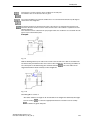
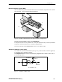
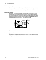
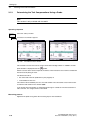
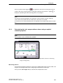
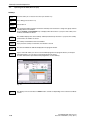
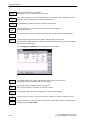
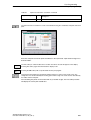
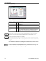
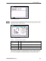
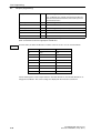
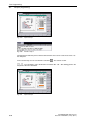
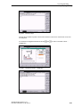
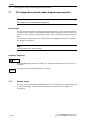
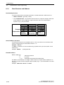
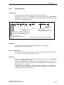
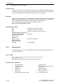
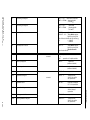
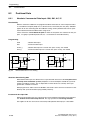
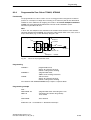
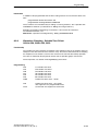
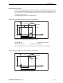
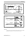
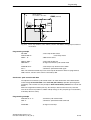
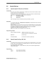
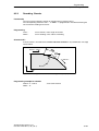
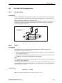
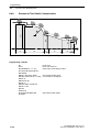
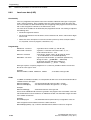
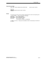
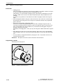
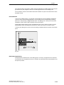
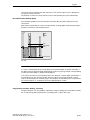
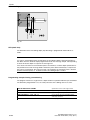
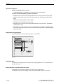
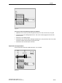
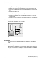
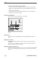
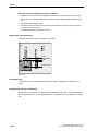
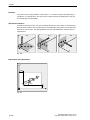
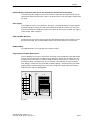
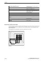
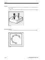
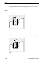
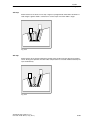
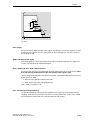
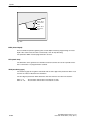
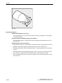
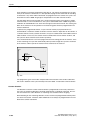
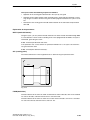
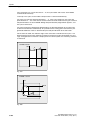
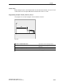
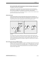
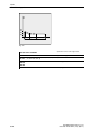
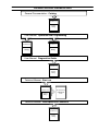
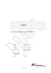
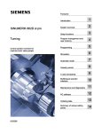
Setting Up
3.1
3.1.2
Entering Tools and Tool Offsets
Determining Tool Offsets (manually)
Functionality
This function can be used to determine the unknown geometry of a tool T.
Prerequisite
The respective tool is changed. In JOG mode, use the cutting edge of the tool to approach a
point on the machine with known machine coordinate values. This can be a workpiece with
a known position.
Procedure
Enter the reference point in the appropriate field Ø or Z0.
Please observe: The assignment of length 1 or 2 to the axis depends on the tool type (turning
tool, drill).
With a turning tool, the reference point for the X axis is a diameter dimension!
Using the actual position of the point F (machine coordinate) and the reference point, the control system can calculate the compensation value assigned to length 1 or length 2 for the axis
preselected.
Note: You can also use a zero offset already determined (e.g. value of G54) as the known
machine coordinate. In this case, use the edge of the tool to approach the workpiece zero
point. If the edge is positioned directly at workpiece zero, the reference point is zero.
F - tool carrier reference point
M - machine zero
F
Actual position X
The offset value in the X axis is a diameter value.
X Machine
Workpiece
Offset
M
Length 1 =?
W - workpiece zero
Actual position Z
W
Z Machine
Length 2=?
Gxx
Fig. 3-6
Determination of length compensation values using the example of a cutting tool
SINUMERIK 802D, 802D base line
6FC5 698-2AA00-0BP3 (11.03) (OP-T)
3-33