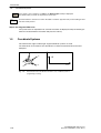
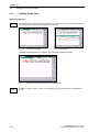
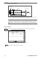
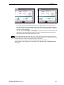
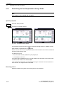
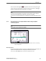
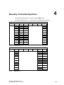
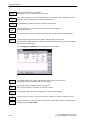
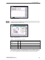
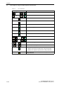
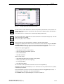
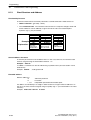
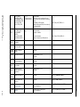
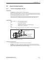
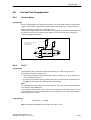
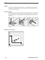
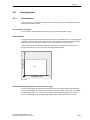
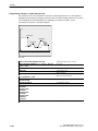
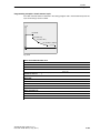
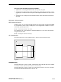
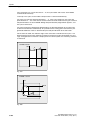
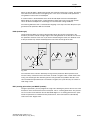
1
Operation and Programming 11/03 Edition sinumerik SINUMERIK 802D SINUMERIK 802D base line Turning Introduction 1 Turning On an Reference-Point Approach 2 Setting Up 3 Manually Controlled Mode 4 Automatic Mode 5 Part Programming 6 System 7 Programming 8 Cycles 9 SINUMERIK 802D Operation and Programming Turning Valid for Control System Software Version SINUMERIK 802D 2 SINUMERIK 802D base line 1 11.03 Edition 3ls SINUMERIK Documentation Printing history Brief details of this edition and previous editions are listed below. IThe status of each edition is shown by the code in the ”Remarks” column. Status code in the “Remarks” column: A . . . . . New documentation. B . . . . . Unrevised reprint with new Order No. C . . . . . Revised edition with new status. If actual changes have been made on the page since the last edition, this is indicated by a new edition coding in the header on the page. Edition 11.00 07.01 10.02 11.03 Order -No. 6FC5 698-2AA00-0BP0 6FC5 698-2AA00-0BP1 6FC5 698-2AA00-0BP2 6FC5 698-2AA00-0BP3 Remark A C C C This Manual is included on the documentation on CD-ROM (DOCONCD) Trademarks SIMATICr, SIMATIC HMIr, SIMATIC NETr, SIROTECr, SINUMERIKr and SIMODRIVEr are registered trademarks of Siemens. Third parties using for their own purposes any other names in this document which refer to trademarks might infringe upon the rights of trademark owners. Other functions not described in this documentation might be executable in the control. This does not, however, represent an obligation to supply such functions with a new control or when servicing. This publication was produced with Interleaf V 7 The reproduction, transmission or use of this document or its contents is not permitted without express written authority. Offenders will be liable for demages. All rights, including rights created by patent grant or registration of utility model or design, are reserved. We have checked that the contents of this document correspond to the hardware and software described. Nonetheless, differences might exist and therefore we cannot guarantee that they are completely identical. The information contained in this document is, however, reviewed regularly and any necessary changes will be included in the next edition. We welcome suggestions for improvement. Subject to change without prior notice. Siemens AG 2003. All rights reserved. Bestell - Nr. 6FC5 698 - 2AA00 - 0BP3 Printed in the Federal Republic of Germany Siemens - Aktiengesellschaft Safety notices This Manual contains notices intended to ensure your personal safety and to avoid material damage. The notices are highlighted by a warning triangle and, depending on the degree of hazard, represented as shown below: ! ! ! Danger indicates that loss of life, severe personal injury or substantial material damage will result if the appropriate precautions are not taken. Warning indicates that loss of life, severe personal injury or substantial material damage may result if the appropriate precautions are not taken. Caution indicates that minor personal injury or material damage may result if the appropriate precautions are not taken. Caution eithout a warning triangle means that material damage can occur if the appropriate precautions are not taken. Attention means that an undesired event or status can occur if the appropriate note is not observed. Note is used to draw your special attention to an important information on the product, the handling of the product or the corresponding part of the documentation. Qualified personnel Start-up and operation of a device may only be carried out by qualified personnel. Qualified personnel as referred to in the safety notices provided in this Manual are persons who are authorized to start up, ground and tag devices, systems and circuits according to the relevant safety standards. Usage as per intended purpose Please observe the following: ! Warning The device may only be used for the cases of application, as intended by the Catalog, and only in conjunction with third-party devices and components recommended or approved by Siemens. The proper and safe operation of the product requires transport, storage and installation according to the relevant instructions and qualified operation and maintenance at the prescribed intervals. SINUMERIK 802D, 802D base line 6FC5 698-2AA00-0BP3 (11.03) (OP-T) v Table of Contents Table of Contents 1 Introduction . . . . . . . . . . . . . . . . . . . . . . . . . . . . . . . . . . . . . . . . . . . . . . . . . . . . . . . . . . . . . . . . . . 1-13 1.1 Screen Layout . . . . . . . . . . . . . . . . . . . . . . . . . . . . . . . . . . . . . . . . . . . . . . . . . . . . . . . . . . . . . . . . 1-13 1.2 Operating Areas . . . . . . . . . . . . . . . . . . . . . . . . . . . . . . . . . . . . . . . . . . . . . . . . . . . . . . . . . . . . . . 1-16 1.3 1.3.1 1.3.2 1.3.3 Accessibility Options . . . . . . . . . . . . . . . . . . . . . . . . . . . . . . . . . . . . . . . . . . . . . . . . . . . . . . . . . . Calculator . . . . . . . . . . . . . . . . . . . . . . . . . . . . . . . . . . . . . . . . . . . . . . . . . . . . . . . . . . . . . . . . . . . . Editing Chinese Characters . . . . . . . . . . . . . . . . . . . . . . . . . . . . . . . . . . . . . . . . . . . . . . . . . . . . . Hotkeys . . . . . . . . . . . . . . . . . . . . . . . . . . . . . . . . . . . . . . . . . . . . . . . . . . . . . . . . . . . . . . . . . . . . . 1-17 1-17 1-22 1-22 1.4 The Help System . . . . . . . . . . . . . . . . . . . . . . . . . . . . . . . . . . . . . . . . . . . . . . . . . . . . . . . . . . . . . 1-23 1.5 Coordinate Systems . . . . . . . . . . . . . . . . . . . . . . . . . . . . . . . . . . . . . . . . . . . . . . . . . . . . . . . . . . . 1-24 2 Turning on and Reference Point Approach . . . . . . . . . . . . . . . . . . . . . . . . . . . . . . . . . . . . . 2-27 3 Setting Up . . . . . . . . . . . . . . . . . . . . . . . . . . . . . . . . . . . . . . . . . . . . . . . . . . . . . . . . . . . . . . . . . . . 3-29 3.1 3.1.1 3.1.2 3.1.3 3.1.4 3.1.5 Entering Tools and Tool Offsets . . . . . . . . . . . . . . . . . . . . . . . . . . . . . . . . . . . . . . . . . . . . . . . . . Creating a New Tool . . . . . . . . . . . . . . . . . . . . . . . . . . . . . . . . . . . . . . . . . . . . . . . . . . . . . . . . . . . Determining Tool Offsets (manually) . . . . . . . . . . . . . . . . . . . . . . . . . . . . . . . . . . . . . . . . . . . . . Determining the Tool Compensations Using a Probe . . . . . . . . . . . . . . . . . . . . . . . . . . . . . . . Determining the tool compensations values using an optical measuring system . . . . . . . . Probe Settings . . . . . . . . . . . . . . . . . . . . . . . . . . . . . . . . . . . . . . . . . . . . . . . . . . . . . . . . . . . . . . . . 3-30 3-32 3-33 3-36 3-37 3-38 3.2 Tool monitoring . . . . . . . . . . . . . . . . . . . . . . . . . . . . . . . . . . . . . . . . . . . . . . . . . . . . . . . . . . . . . . . 3-40 3.3 3.3.1 Entering/Modifying Zero Offset . . . . . . . . . . . . . . . . . . . . . . . . . . . . . . . . . . . . . . . . . . . . . . . . . . Determining Zero Offset . . . . . . . . . . . . . . . . . . . . . . . . . . . . . . . . . . . . . . . . . . . . . . . . . . . . . . . . 3-42 3-43 3.4 Programming Setting Data - Operating Area ”Parameters” . . . . . . . . . . . . . . . . . . . . . . . . . . 3-44 3.5 R Parameters - Operating Area ”Offset/Parameters” . . . . . . . . . . . . . . . . . . . . . . . . . . . . . . . . 3-47 Manually Controlled Operation . . . . . . . . . . . . . . . . . . . . . . . . . . . . . . . . . . . . . . . . . . . . . . . . 4-49 4.1 4.1.1 Jog Mode - Operating Area ”Position” . . . . . . . . . . . . . . . . . . . . . . . . . . . . . . . . . . . . . . . . . . . . Assigning Handwheels . . . . . . . . . . . . . . . . . . . . . . . . . . . . . . . . . . . . . . . . . . . . . . . . . . . . . . . . . 4-50 4-53 4.2 4.2.1 Operating Mode MDA (Manual Input) . . . . . . . . . . . . . . . . . . . . . . . . . . . . . . . . . . . . . . . . . . . . Face Turning . . . . . . . . . . . . . . . . . . . . . . . . . . . . . . . . . . . . . . . . . . . . . . . . . . . . . . . . . . . . . . . . . 4-54 4-57 Automatic Mode . . . . . . . . . . . . . . . . . . . . . . . . . . . . . . . . . . . . . . . . . . . . . . . . . . . . . . . . . . . . . . 5-61 5.1 Selecting and Starting a Part Program . . . . . . . . . . . . . . . . . . . . . . . . . . . . . . . . . . . . . . . . . . . . 5-65 5.2 Block Search - Operating Area “Machine” . . . . . . . . . . . . . . . . . . . . . . . . . . . . . . . . . . . . . . . . . 5-66 5.3 Stopping/Aborting a Part Program . . . . . . . . . . . . . . . . . . . . . . . . . . . . . . . . . . . . . . . . . . . . . . . 5-67 5.4 Reapproach after Interruption . . . . . . . . . . . . . . . . . . . . . . . . . . . . . . . . . . . . . . . . . . . . . . . . . . . 5-68 5.5 Repositioning after interruption . . . . . . . . . . . . . . . . . . . . . . . . . . . . . . . . . . . . . . . . . . . . . . . . . . 5-68 5.6 Program Execution from External (RS232 Interface) . . . . . . . . . . . . . . . . . . . . . . . . . . . . . . . . 5-69 Part Programming . . . . . . . . . . . . . . . . . . . . . . . . . . . . . . . . . . . . . . . . . . . . . . . . . . . . . . . . . . . . 6-71 6.1 Entering a New Program - Operating Area ”Program” . . . . . . . . . . . . . . . . . . . . . . . . . . . . . . . 6-74 6.2 Editing a Part Program - Operating Mode ”Program” . . . . . . . . . . . . . . . . . . . . . . . . . . . . . . . . 6-75 6.3 Blueprint programming . . . . . . . . . . . . . . . . . . . . . . . . . . . . . . . . . . . . . . . . . . . . . . . . . . . . . . . . . 6-77 6.4 Simulation . . . . . . . . . . . . . . . . . . . . . . . . . . . . . . . . . . . . . . . . . . . . . . . . . . . . . . . . . . . . . . . . . . . 6-96 6.5 Data Transfer via the RS232 Interface . . . . . . . . . . . . . . . . . . . . . . . . . . . . . . . . . . . . . . . . . . . . 6-97 4 5 6 vi SINUMERIK 802D, 802D base line 6FC5 698-2AA00-0BP3 (11.03) (OP-T) Table of Contents 7 System . . . . . . . . . . . . . . . . . . . . . . . . . . . . . . . . . . . . . . . . . . . . . . . . . . . . . . . . . . . . . . . . . . . . . . 7.1 7.1.1 7.1.2 8 7-99 PLC diagnosis using the ladder diagram representation . . . . . . . . . . . . . . . . . . . . . . . . . . . . . 7-120 Screen layout . . . . . . . . . . . . . . . . . . . . . . . . . . . . . . . . . . . . . . . . . . . . . . . . . . . . . . . . . . . . . . . . 7-120 Operating options . . . . . . . . . . . . . . . . . . . . . . . . . . . . . . . . . . . . . . . . . . . . . . . . . . . . . . . . . . . . . 7-121 Programming . . . . . . . . . . . . . . . . . . . . . . . . . . . . . . . . . . . . . . . . . . . . . . . . . . . . . . . . . . . . . . . . 8-131 8.1 8.1.1 8.1.2 8.1.3 8.1.4 8.1.5 8.1.6 Fundamentals of NC Programming . . . . . . . . . . . . . . . . . . . . . . . . . . . . . . . . . . . . . . . . . . . . . . Program Names . . . . . . . . . . . . . . . . . . . . . . . . . . . . . . . . . . . . . . . . . . . . . . . . . . . . . . . . . . . . . . Program Structure . . . . . . . . . . . . . . . . . . . . . . . . . . . . . . . . . . . . . . . . . . . . . . . . . . . . . . . . . . . . . Word Structure and Address . . . . . . . . . . . . . . . . . . . . . . . . . . . . . . . . . . . . . . . . . . . . . . . . . . . . Block Structure . . . . . . . . . . . . . . . . . . . . . . . . . . . . . . . . . . . . . . . . . . . . . . . . . . . . . . . . . . . . . . . Character Set . . . . . . . . . . . . . . . . . . . . . . . . . . . . . . . . . . . . . . . . . . . . . . . . . . . . . . . . . . . . . . . . List of Statements . . . . . . . . . . . . . . . . . . . . . . . . . . . . . . . . . . . . . . . . . . . . . . . . . . . . . . . . . . . . . 8-131 8-131 8-131 8-132 8-133 8-134 8-136 8.2 8.2.1 8.2.2 8.2.3 8.2.4 8.2.5 8.2.6 Positional Data . . . . . . . . . . . . . . . . . . . . . . . . . . . . . . . . . . . . . . . . . . . . . . . . . . . . . . . . . . . . . . . Absolute / Incremental Data Input: G90, G91, AC, IC . . . . . . . . . . . . . . . . . . . . . . . . . . . . . . . Metric and Inch Dimensions: G71, G70, G710, G700 . . . . . . . . . . . . . . . . . . . . . . . . . . . . . . . Radius / Diameter Programming: DIAMOF, DIAMON . . . . . . . . . . . . . . . . . . . . . . . . . . . . . . . Programmable Zero Offset: TRANS, ATRANS . . . . . . . . . . . . . . . . . . . . . . . . . . . . . . . . . . . . . Programmable Scaling Factor: SCALE, ASCALE . . . . . . . . . . . . . . . . . . . . . . . . . . . . . . . . . . Workpiece Clamping - Settable Zero Offset: G54 to G59, G500, G53, G153 . . . . . . . . . . . . . . . . . . . . . . . . . . . . . . . . . . . . . . . . . . . . . . . . . . Programmable Working Area Limitation: G25, G26, WALIMON, WALIMOF . . . . . . . . . . . . . . . . . . . . . . . . . . . . . . . . . . . . . . . . . . . . . . . 8-150 8-150 8-151 8-152 8-153 8-154 8.3 8.3.1 8.3.2 8.3.3 8.3.4 8.3.5 8.3.6 8.3.7 8.3.8 8.3.9 8.3.10 8.3.11 8.3.12 8.3.13 8.3.14 8.3.15 8.3.16 8.3.17 8.3.18 8.3.19 Axis Movements . . . . . . . . . . . . . . . . . . . . . . . . . . . . . . . . . . . . . . . . . . . . . . . . . . . . . . . . . . . . . . Linear Interpolation at Rapid Traverse: G0 . . . . . . . . . . . . . . . . . . . . . . . . . . . . . . . . . . . . . . . . Linear Interpolation with Feed: G1 . . . . . . . . . . . . . . . . . . . . . . . . . . . . . . . . . . . . . . . . . . . . . . . Circular Interpolation: G2, G3 . . . . . . . . . . . . . . . . . . . . . . . . . . . . . . . . . . . . . . . . . . . . . . . . . . . Circular Interpolation via Intermediate Point: CIP . . . . . . . . . . . . . . . . . . . . . . . . . . . . . . . . . . . Circle with Tangential Transition: CT . . . . . . . . . . . . . . . . . . . . . . . . . . . . . . . . . . . . . . . . . . . . . Thread Cutting with Constant Lead: G33 . . . . . . . . . . . . . . . . . . . . . . . . . . . . . . . . . . . . . . . . . Thread cutting with variable lead: G34, G35 . . . . . . . . . . . . . . . . . . . . . . . . . . . . . . . . . . . . . . . Thread interpolation: G331, G332 . . . . . . . . . . . . . . . . . . . . . . . . . . . . . . . . . . . . . . . . . . . . . . . Fixed -Point Approach: G75 . . . . . . . . . . . . . . . . . . . . . . . . . . . . . . . . . . . . . . . . . . . . . . . . . . . . Reference Point Approach: G74 . . . . . . . . . . . . . . . . . . . . . . . . . . . . . . . . . . . . . . . . . . . . . . . . . Measuring with Switching Tracer: MEAS, MEAW . . . . . . . . . . . . . . . . . . . . . . . . . . . . . . . . . . Feed F . . . . . . . . . . . . . . . . . . . . . . . . . . . . . . . . . . . . . . . . . . . . . . . . . . . . . . . . . . . . . . . . . . . . . . Exact Stop / Continuous -Path Control Mode: G9, G60, G64 . . . . . . . . . . . . . . . . . . . . . . . . . Acceleration Behavior: BRISK, SOFT . . . . . . . . . . . . . . . . . . . . . . . . . . . . . . . . . . . . . . . . . . . . Percentage Acceleration Compensation: ACC . . . . . . . . . . . . . . . . . . . . . . . . . . . . . . . . . . . . . Traversing with Feedforward Control: FFWON, FFWOF . . . . . . . . . . . . . . . . . . . . . . . . . . . . . 3rd and 4th Axes . . . . . . . . . . . . . . . . . . . . . . . . . . . . . . . . . . . . . . . . . . . . . . . . . . . . . . . . . . . . . . Dwell Time: G4 . . . . . . . . . . . . . . . . . . . . . . . . . . . . . . . . . . . . . . . . . . . . . . . . . . . . . . . . . . . . . . . Travel to fixed stop . . . . . . . . . . . . . . . . . . . . . . . . . . . . . . . . . . . . . . . . . . . . . . . . . . . . . . . . . . . . 8-158 8-158 8-159 8-160 8-163 8-163 8-164 8-167 8-168 8-169 8-169 8-170 8-171 8-172 8-174 8-175 8-176 8-176 8-177 8-178 8.4 8.4.1 8.4.2 8.4.3 8.4.4 8.4.5 Spindle Motions . . . . . . . . . . . . . . . . . . . . . . . . . . . . . . . . . . . . . . . . . . . . . . . . . . . . . . . . . . . . . . . Spindle Speed S; Directions of Rotation . . . . . . . . . . . . . . . . . . . . . . . . . . . . . . . . . . . . . . . . . . Spindle Speed Limiting: G25, G26 . . . . . . . . . . . . . . . . . . . . . . . . . . . . . . . . . . . . . . . . . . . . . . . Positioning the Spindle: SPOS . . . . . . . . . . . . . . . . . . . . . . . . . . . . . . . . . . . . . . . . . . . . . . . . . . Gear stages . . . . . . . . . . . . . . . . . . . . . . . . . . . . . . . . . . . . . . . . . . . . . . . . . . . . . . . . . . . . . . . . . . 2nd spindle . . . . . . . . . . . . . . . . . . . . . . . . . . . . . . . . . . . . . . . . . . . . . . . . . . . . . . . . . . . . . . . . . . 8-181 8-181 8-181 8-182 8-183 8-183 8.5 8.5.1 8.5.2 8.5.3 Special Turning Functions . . . . . . . . . . . . . . . . . . . . . . . . . . . . . . . . . . . . . . . . . . . . . . . . . . . . . . Constant Cutting Speed: G96, G97 . . . . . . . . . . . . . . . . . . . . . . . . . . . . . . . . . . . . . . . . . . . . . . Rounding, Chamfer . . . . . . . . . . . . . . . . . . . . . . . . . . . . . . . . . . . . . . . . . . . . . . . . . . . . . . . . . . . Contour Definition Programming . . . . . . . . . . . . . . . . . . . . . . . . . . . . . . . . . . . . . . . . . . . . . . . . . 8-185 8-185 8-187 8-188 8.6 8.6.1 8.6.2 8.6.3 Tool and Tool Compensation . . . . . . . . . . . . . . . . . . . . . . . . . . . . . . . . . . . . . . . . . . . . . . . . . . . . General Notes . . . . . . . . . . . . . . . . . . . . . . . . . . . . . . . . . . . . . . . . . . . . . . . . . . . . . . . . . . . . . . . . Tool T . . . . . . . . . . . . . . . . . . . . . . . . . . . . . . . . . . . . . . . . . . . . . . . . . . . . . . . . . . . . . . . . . . . . . . . Tool Offset Number D . . . . . . . . . . . . . . . . . . . . . . . . . . . . . . . . . . . . . . . . . . . . . . . . . . . . . . . . . . 8-191 8-191 8-191 8-192 8.2.7 SINUMERIK 802D, 802D base line 6FC5 698-2AA00-0BP3 (11.03) (OP-T) 8-155 8-156 vii Table of Contents 9 viii 8.6.4 8.6.5 8.6.6 8.6.7 8.6.8 8.6.9 8.6.10 Selection of Tool Radius Compensation: G41, G42 . . . . . . . . . . . . . . . . . . . . . . . . . . . . . . . . . Corner Behavior: G450, G451 . . . . . . . . . . . . . . . . . . . . . . . . . . . . . . . . . . . . . . . . . . . . . . . . . . Tool Radius Compensation OFF: G40 . . . . . . . . . . . . . . . . . . . . . . . . . . . . . . . . . . . . . . . . . . . . Special Cases of Tool Radius Compensation . . . . . . . . . . . . . . . . . . . . . . . . . . . . . . . . . . . . . . Example of Tool Radius Compensation . . . . . . . . . . . . . . . . . . . . . . . . . . . . . . . . . . . . . . . . . . . Using milling tools . . . . . . . . . . . . . . . . . . . . . . . . . . . . . . . . . . . . . . . . . . . . . . . . . . . . . . . . . . . . . Tool compensation special cases . . . . . . . . . . . . . . . . . . . . . . . . . . . . . . . . . . . . . . . . . . . . . . . . 8-195 8-197 8-198 8-199 8-200 8-201 8-203 8.7 Miscellaneous Function M . . . . . . . . . . . . . . . . . . . . . . . . . . . . . . . . . . . . . . . . . . . . . . . . . . . . . . 8-204 8.8 H function . . . . . . . . . . . . . . . . . . . . . . . . . . . . . . . . . . . . . . . . . . . . . . . . . . . . . . . . . . . . . . . . . . . . 8-205 8.9 8.9.1 8.9.2 8.9.3 Arithmetic parameters R, LUD and PLC variables . . . . . . . . . . . . . . . . . . . . . . . . . . . . . . . . . . Arithmetic parameters R . . . . . . . . . . . . . . . . . . . . . . . . . . . . . . . . . . . . . . . . . . . . . . . . . . . . . . . Local user data (LUD) . . . . . . . . . . . . . . . . . . . . . . . . . . . . . . . . . . . . . . . . . . . . . . . . . . . . . . . . . Reading and writing PLC variables . . . . . . . . . . . . . . . . . . . . . . . . . . . . . . . . . . . . . . . . . . . . . . 8-206 8-206 8-208 8-209 8.10 8.10.1 8.10.2 8.10.3 8.10.4 Program Jumps . . . . . . . . . . . . . . . . . . . . . . . . . . . . . . . . . . . . . . . . . . . . . . . . . . . . . . . . . . . . . . . Jump Destination for Program Jumps . . . . . . . . . . . . . . . . . . . . . . . . . . . . . . . . . . . . . . . . . . . . Unconditional Program Jumps . . . . . . . . . . . . . . . . . . . . . . . . . . . . . . . . . . . . . . . . . . . . . . . . . . Conditional Program Jumps . . . . . . . . . . . . . . . . . . . . . . . . . . . . . . . . . . . . . . . . . . . . . . . . . . . . Programming Example of Jumps . . . . . . . . . . . . . . . . . . . . . . . . . . . . . . . . . . . . . . . . . . . . . . . . 8-210 8-210 8-210 8-211 8-213 8.11 8.11.1 8.11.2 Subroutine Technique . . . . . . . . . . . . . . . . . . . . . . . . . . . . . . . . . . . . . . . . . . . . . . . . . . . . . . . . . 8-214 General . . . . . . . . . . . . . . . . . . . . . . . . . . . . . . . . . . . . . . . . . . . . . . . . . . . . . . . . . . . . . . . . . . . . . . 8-214 Calling Machining Cycles . . . . . . . . . . . . . . . . . . . . . . . . . . . . . . . . . . . . . . . . . . . . . . . . . . . . . . . 8-216 8.12 8.12.1 8.12.2 Timer and Workpiece Counter . . . . . . . . . . . . . . . . . . . . . . . . . . . . . . . . . . . . . . . . . . . . . . . . . . 8-217 Runtime Timer . . . . . . . . . . . . . . . . . . . . . . . . . . . . . . . . . . . . . . . . . . . . . . . . . . . . . . . . . . . . . . . . 8-217 Workpiece Counter . . . . . . . . . . . . . . . . . . . . . . . . . . . . . . . . . . . . . . . . . . . . . . . . . . . . . . . . . . . . 8-218 8.13 8.13.1 8.13.2 8.13.3 Language commands for tool monitoring . . . . . . . . . . . . . . . . . . . . . . . . . . . . . . . . . . . . . . . . . Overview: Tool monitoring . . . . . . . . . . . . . . . . . . . . . . . . . . . . . . . . . . . . . . . . . . . . . . . . . . . . . . Tool life monitoring . . . . . . . . . . . . . . . . . . . . . . . . . . . . . . . . . . . . . . . . . . . . . . . . . . . . . . . . . . . . Count monitoring . . . . . . . . . . . . . . . . . . . . . . . . . . . . . . . . . . . . . . . . . . . . . . . . . . . . . . . . . . . . . . 8.14 8.14.1 8.14.2 Milling on turning machines . . . . . . . . . . . . . . . . . . . . . . . . . . . . . . . . . . . . . . . . . . . . . . . . . . . . . 8-225 Milling face ends - TRANSMIT . . . . . . . . . . . . . . . . . . . . . . . . . . . . . . . . . . . . . . . . . . . . . . . . . . 8-225 Milling of peripheral surfaces - TRACYL . . . . . . . . . . . . . . . . . . . . . . . . . . . . . . . . . . . . . . . . . . 8-227 8.15 Equivalent G Functions with SINUMERIK 802S - Turning . . . . . . . . . . . . . . . . . . . . . . . . . . . 8-232 8-220 8-220 8-221 8-222 Cycles . . . . . . . . . . . . . . . . . . . . . . . . . . . . . . . . . . . . . . . . . . . . . . . . . . . . . . . . . . . . . . . . . . . . . . . 9-233 9.1 Overview of cycles . . . . . . . . . . . . . . . . . . . . . . . . . . . . . . . . . . . . . . . . . . . . . . . . . . . . . . . . . . . . 9-233 9.2 Programming cycles . . . . . . . . . . . . . . . . . . . . . . . . . . . . . . . . . . . . . . . . . . . . . . . . . . . . . . . . . . . 9-234 9.3 Graphical cycle support in the program editor . . . . . . . . . . . . . . . . . . . . . . . . . . . . . . . . . . . . . 9-236 9.4 9.4.1 9.4.2 9.4.3 9.4.4 9.4.5 9.4.6 9.4.7 9.4.8 9.4.9 9.4.10 9.4.11 9.4.12 9.4.13 9.4.14 Drilling cycles . . . . . . . . . . . . . . . . . . . . . . . . . . . . . . . . . . . . . . . . . . . . . . . . . . . . . . . . . . . . . . . . . General . . . . . . . . . . . . . . . . . . . . . . . . . . . . . . . . . . . . . . . . . . . . . . . . . . . . . . . . . . . . . . . . . . . . . . Preconditions . . . . . . . . . . . . . . . . . . . . . . . . . . . . . . . . . . . . . . . . . . . . . . . . . . . . . . . . . . . . . . . . . Drilling, centering – CYCLE81 . . . . . . . . . . . . . . . . . . . . . . . . . . . . . . . . . . . . . . . . . . . . . . . . . . Center drilling – CYCLE82 . . . . . . . . . . . . . . . . . . . . . . . . . . . . . . . . . . . . . . . . . . . . . . . . . . . . . . Deep hole drilling – CYCLE83 . . . . . . . . . . . . . . . . . . . . . . . . . . . . . . . . . . . . . . . . . . . . . . . . . . Rigid tapping – CYCLE84 . . . . . . . . . . . . . . . . . . . . . . . . . . . . . . . . . . . . . . . . . . . . . . . . . . . . . . Tapping with compensation chuck – CYCLE840 . . . . . . . . . . . . . . . . . . . . . . . . . . . . . . . . . . . Reaming 1 (boring 1) – CYCLE85 . . . . . . . . . . . . . . . . . . . . . . . . . . . . . . . . . . . . . . . . . . . . . . . Boring (boring 2) – CYCLE86 . . . . . . . . . . . . . . . . . . . . . . . . . . . . . . . . . . . . . . . . . . . . . . . . . . . Boring with Stop 1 (boring 3) – CYCLE87 . . . . . . . . . . . . . . . . . . . . . . . . . . . . . . . . . . . . . . . . . Drilling with stop – CYCLE88 . . . . . . . . . . . . . . . . . . . . . . . . . . . . . . . . . . . . . . . . . . . . . . . . . . . Reaming 2 (boring 5) – CYCLE89 . . . . . . . . . . . . . . . . . . . . . . . . . . . . . . . . . . . . . . . . . . . . . . . Row of holes – HOLES1 . . . . . . . . . . . . . . . . . . . . . . . . . . . . . . . . . . . . . . . . . . . . . . . . . . . . . . . Circle of holes – HOLES2 . . . . . . . . . . . . . . . . . . . . . . . . . . . . . . . . . . . . . . . . . . . . . . . . . . . . . . 9.5 Turning cycles . . . . . . . . . . . . . . . . . . . . . . . . . . . . . . . . . . . . . . . . . . . . . . . . . . . . . . . . . . . . . . . . 9-277 9-238 9-238 9-238 9-240 9-243 9-245 9-249 9-252 9-256 9-259 9-262 9-265 9-267 9-269 9-273 SINUMERIK 802D, 802D base line 6FC5 698-2AA00-0BP3 (11.03) (OP-T) Table of Contents 9.5.1 9.5.2 9.5.3 9.5.4 9.5.5 9.5.6 9.5.7 Preconditions . . . . . . . . . . . . . . . . . . . . . . . . . . . . . . . . . . . . . . . . . . . . . . . . . . . . . . . . . . . . . . . . . Grooving – CYCLE93 . . . . . . . . . . . . . . . . . . . . . . . . . . . . . . . . . . . . . . . . . . . . . . . . . . . . . . . . . . Undercut form E .. F – CYCLE94 . . . . . . . . . . . . . . . . . . . . . . . . . . . . . . . . . . . . . . . . . . . . . . . . Stock removal – CYCLE95 . . . . . . . . . . . . . . . . . . . . . . . . . . . . . . . . . . . . . . . . . . . . . . . . . . . . . Thread undercut – CYCLE96 . . . . . . . . . . . . . . . . . . . . . . . . . . . . . . . . . . . . . . . . . . . . . . . . . . . Thread cutting – CYCLE97 . . . . . . . . . . . . . . . . . . . . . . . . . . . . . . . . . . . . . . . . . . . . . . . . . . . . . Chaining of threads – CYCLE98 . . . . . . . . . . . . . . . . . . . . . . . . . . . . . . . . . . . . . . . . . . . . . . . . . 9-277 9-279 9-287 9-291 9-304 9-308 9-314 9.6 9.6.1 9.6.2 9.6.3 9.6.4 Error Messages and Error Handling . . . . . . . . . . . . . . . . . . . . . . . . . . . . . . . . . . . . . . . . . . . . . . General notes . . . . . . . . . . . . . . . . . . . . . . . . . . . . . . . . . . . . . . . . . . . . . . . . . . . . . . . . . . . . . . . . Error handling in the cycles . . . . . . . . . . . . . . . . . . . . . . . . . . . . . . . . . . . . . . . . . . . . . . . . . . . . . Overview of cycle alarms . . . . . . . . . . . . . . . . . . . . . . . . . . . . . . . . . . . . . . . . . . . . . . . . . . . . . . . Messages in the cycles . . . . . . . . . . . . . . . . . . . . . . . . . . . . . . . . . . . . . . . . . . . . . . . . . . . . . . . . 9-321 9-321 9-321 9-321 9-323 SINUMERIK 802D, 802D base line 6FC5 698-2AA00-0BP3 (11.03) (OP-T) ix SINUMERIK 802D Key Definition Deletion key (Backspace) & Deletion key Insertion key Tabulator ENTER / Input key Position operating area key Program operating area key Parameters operating area key Program Manager operating area key Alarm/System operating area key Not assigned Recall key Paging keys ETC key Acknowledge Alarm key Not assigned Cursor keys Info key Selection key/toggle key Shift key Control key Alphanumeric keys Double assignment on the Shift level Alt key SPACE (INSERT) x Numerical keys Double assignment on the Shift level SINUMERIK 802D, 802D base line 6FC5 698-2AA00-0BP3 (11.03) (OP-T) External machine control panel User -defined key with LED User -defined key with LED INCREMENT JOG REFERENCE POINT 80 90 70 AUTOMATIC 100 60 110 SINGLE BLOCK 120 MANUAL DATA 20 10 6 40 60 70 2 SPINDLE START CCW rotation 80 90 100 110 0 SPINDLE START CW rotation 120 SPINDLE STOP RAPID TRAVERSE OVERRIDE Rapid traverse override Reset X axis NC STOP Z axis NC START % emergency stop % Feed override Spindle override SINUMERIK 802D, 802D base line 6FC5 698-2AA00-0BP3 (11.03) (OP-T) xi notice xii SINUMERIK 802D, 802D base line 6FC5 698-2AA00-0BP3 (11.03) (OP-T) 1 Introduction Note In the present Manual, SINUMERIK 802D base line is further referred to as 802D - bl. 1.1 Screen Layout Status area G function Application area Tip and softkey area Fig. 1-1 Screen layout The screen is divided into the following main areas: S Status area S Application area S Tip and softkey area SINUMERIK 802D, 802D base line 6FC5 698-2AA00-0BP3 (11.03) (OP-T) 1-13 Introduction 1.1 Screen Layout Status area Fig. 1-2 Table 1-1 Display Element Status area Explanation of the display elements in the status area Display Meaning Active operating area, active mode Position 1 JOG; 1 INC, 10 INC, 100 INC, 1000 INC, VAR INC (incremental evaluation in JOG mode) MDA AUTOMATIC Offset Program Program Manager System Alarm Marked as an ”external language” using G291 Alarm and message line 2 Th following The f ll i is i displayed di l d (either/or): ( ith / ) 1. Alarm number with alarm text 2. Message text Program status 3 1-14 RESET Program aborted / basic status RUN Program running STOP Program stopped 4 Program controls in Automatic mode 5 Reserved 6 NC messages 7 Selected part program (main program) SINUMERIK 802D, 802D base line 6FC5 698-2AA00-0BP3 (11.03) (OP-T) Introduction 1.1 Screen Layout Tip and softkey area Fig. 1-3 Table 1-2 Display Element Tip and softkey area Explanation of the display elements in the tip and softkey area Display 1 2 Meaning Recall symbol Pressing the Recall key lets you return to the next higher level. Tip line Displays tips for the operator MMC status information ETC is possible (If you press this key, the horizontal softkey bar will display further functions.) 3 Mixed notation active Data transfer running Link with the PLC programming tool active 4 Softkey bar vertical and horizontal Standard softkeys Use this softkey to quit the screen form. Use this softkey to cancel input; the window will be quitted. Pressing this softkey will complete your input and start the calculation. SINUMERIK 802D, 802D base line 6FC5 698-2AA00-0BP3 (11.03) (OP-T) 1-15 Introduction 1.2 Operating Areas Pressing this softkey will complete your input and accept the entered values. This function is used to switch over the screen form from diameter programming to radius programming. 1.2 Operating Areas The functions of the control system can be carried out in the following operating areas: Position Machine operation Offset/Parameters Input of compensation values and setting data Program Creation of part programs Program Manager Part program directory System Diagnosis, start -up Alarm Alarm and message lists To switch to a different operating area, press the appropriate key (hardkey). Protection levels The input or modification of data in the control system is password-protected in sensible places. In the menus listed below the input or modification of data depends on the protection level set. 1-16 S Tool offsets S Zero offsets S Setting data S RS232 settings S Program creation / program correction SINUMERIK 802D, 802D base line 6FC5 698-2AA00-0BP3 (11.03) (OP-T) Introduction 1.3 1.3 1.3.1 Accessibility Options Accessibility Options Calculator The calculator function can be activated from any operating area using SHIFT and “=”. To calculate terms, the four basic arithmetic operations can be used, as well as the functions “sine”, “cosine”, “squaring” and “square root”. A bracket function is provided to calculate nested terms. The bracketing depth is unlimited. If the input field is already occupied by a value, the function will accept this value into the input line of the calculator. When you press the Input key, the result is calculated and displayed in the calculator. Pressing the Accept softkey enters the result in the input field at the current cursor position of the part program editor and closes the calculator automatically. Note If an input field is in the editing mode, it is possible to restore the original status using the ”Toggle” key. Fig. 1-4 Calculator Characters permitted for input +, *, / Basic arithmetic operations S Sine function The X value (in degrees) before the input cursor is replaced by the value sin(X). C Cosine function The X value (in degrees) before the input cursor is replaced by the value cos(X). Q Square function The X value before the input cursor is replaced by the value X2. SINUMERIK 802D, 802D base line 6FC5 698-2AA00-0BP3 (11.03) (OP-T) 1-17 Introduction 1.3 Accessibility Options R Square root function The X value before the input cursor is replaced by the value √X. () Bracket function (X+Y)*Z Calculation examples Task Input -> Result 100 + (67*3) 100+67*3 -> 301 sin(45_) 45 S -> 0.707107 cos(45_) 45 C -> 0.707107 42 4 Q -> 16 √4 4 R -> 2 (34+3*2)*10 (34+3*2)*10 -> 400 To calculate auxiliary points on a contour, the calculator provides the following functions: S Calculating the tangential transition between a circle sector and a straight line S Moving a point in the plane S Converting polar coordinates to Cartesian coordinates S Adding the second end point of a straight line/straight line contour section given from an angular relation Softkeys This function is used to calculate a point on a circle. The point results from the angle of the tangent created, the radius and the direction of rotation of the circle. Fig. 1-5 Enter the circle center, the angle of the tangent and the circle radius. G2/G3 1-18 Use the softkey G2 / G3 to define the direction of rotation of the circle. SINUMERIK 802D, 802D base line 6FC5 698-2AA00-0BP3 (11.03) (OP-T) Introduction 1.3 Accessibility Options When you press this softkey, the abscissa and ordinate values are calculated. The abscissa is the first axis, and the ordinate is the second axis of the plane. The value of the abscissa is copied into the input box from which the calculator function has been called, and the value of the ordinate is copied into the next following input box. If the function has been called from the part program editor, the coordinates are saved with the axis names of the selected basic plane. Example: Calculate the intersection point between circle sector in plane G18. Given: and straight line Radius: 10 Circle center: Z 147 X103 Connection angle of the straight line: -45 5 X Z X Z Result: Z = 154.071 X = 110.071 This function calculates the Cartesian coordinates of a point in the plane, which is to be linked with a point (PP) on a straight line. For calculation, the distance between the points and the slope angle (A2) of the new straight line to be created with reference to the slope (A1) of the given straight line must be known. Fig. 1-6 Enter the following coordinates or angles: S the coordinates of the given point (PP) S the rise angle of the straight line (A1) S the distance of the new point with reference to PP S the rise angle of the connecting straight line (A2) with reference to A1 SINUMERIK 802D, 802D base line 6FC5 698-2AA00-0BP3 (11.03) (OP-T) 1-19 Introduction 1.3 Accessibility Options When you press this softkey, the Cartesian coordinates are calculated, which are then copied into two input fields following another to one. The value of the abscissa is copied into the input box from which the calculator function has been called, and the value of the ordinate is copied into the next following input box. If the function has been called from the part program editor, the coordinates are saved with the axis names of the selected basic plane. This function converts the given polar coordinates into Cartesian coordinates. Fig. 1-7 Enter reference point, vector length and slope angle. When you press this softkey, the Cartesian coordinates are calculated, which are then copied into two input fields following another to one. The value of the abscissa is copied into the input box from which the calculator function has been called, and the value of the ordinate is copied into the next following input box. If the function has been called from the part program editor, the coordinates are saved with the axis names of the selected basic plane. This function is used to calculate the missing end point of the straight line/straight line contour section whereby the second straight line stands vertically on the first straight line. The following values of the straight line are known: Straight line 1: Start point and slope angle Straight line 2: Length and one end point in the Cartesian coordinate system Fig. 1-8 1-20 SINUMERIK 802D, 802D base line 6FC5 698-2AA00-0BP3 (11.03) (OP-T) Introduction 1.3 Accessibility Options This function is used to select the given coordinate of the end point. The ordinate value or the abscissa value is given. The second straight line is rotated in CW direction or in counterclockwise direction by 90 degrees relative to the first straight line. The missing end point is calculated. The value of the abscissa is copied into the input box from which the calculator function has been called, and the value of the ordinate is copied into the next following input box. If the function has been called from the part program editor, the coordinates are saved with the axis names of the selected basic plane. Example Fig. 1-9 Add the drawing above by the value of the center circle in order to be able to calculate then the intersection point between the circle sector of the straight line. The missing coordinate of the center point is calculated using the calculator function tangential transition stands vertically on the straight line. , since the radius in the Fig. 1-10 Calculating M1 in section 1: The radius stands at an angle of 90° turned CW on the straight-line defined by the angle. Use the softkey to select the appropriate direction of rotation. Use the softkey to define the given end point. SINUMERIK 802D, 802D base line 6FC5 698-2AA00-0BP3 (11.03) (OP-T) 1-21 Introduction 1.3 Accessibility Options Enter the coordinates of the pole, the slope angle of the straight line, the ordinate angle of the end point and the circle radius as the length. Fig. 1-11 Result: 1.3.2 X = 60 Z = -44.601 Editing Chinese Characters This function is only available in the Chinese language version. The control system provides a function for editing Chinese characters in the program editor and in the PLC alarm text editor. After activation, type the phonetic alphabet of the searched character in the input box. The editor will then offer various characters for this sound, from which you can choose the desired one by entering either of the digits 1 to 9. Fig. 1-12 Alt 1.3.3 Chinese editor S is used to turn on/turn off the editor Hotkeys This operator control can be used to select, copy, cut and delete texts using special key commands. This functions are available both for the part program editor and for input fields. 1-22 CTRL C Copy CTRL B Select CTRL X Cut CTRL V Paste Alt L is used to switch to mixed notation SINUMERIK 802D, 802D base line 6FC5 698-2AA00-0BP3 (11.03) (OP-T) Introduction 1.4 Alt or Info key 1.4 H The Help System Help system The Help System To activate the help system, use the Info key. It offers a brief description for all essential operating functions. Further, the help feature contains the following topics: S Overview of the NC commands with a brief description S Cycle programming S Explanation of the drive alarms Fig. 1-13 Show This function opens the topic selected. Fig. 1-14 Go to topic Table of contents of the help system Description with regard to a help topic Use this function to select cross references. A cross reference is marked by the characters “>>....<<”. This softkey is only unhidden if a cross reference is displayed in the application area. SINUMERIK 802D, 802D base line 6FC5 698-2AA00-0BP3 (11.03) (OP-T) 1-23 Introduction 1.5 Coordinate Systems Back to topic Find If you select a cross reference, in addition, the Back to topic softkey is displayed. This function lets you return to the previous screen form. Use this function to search for a term in the table of contents. Type the term you are looking for and start the search process. Help in the Program Editor area The system offers an explanation for each NC instruction. To display the help text directly, position the cursor behind the instruction and press the Info key. 1.5 Coordinate Systems For machine tools, right-handed, right-angled coordinate systems are used. The movements on the machine are described as a relative movement between tool and workpiece. +Z +Y +X Fig. 1-15 1-24 +X +Z Determination of the axis directions another to one; coordinate system for programming on turning SINUMERIK 802D, 802D base line 6FC5 698-2AA00-0BP3 (11.03) (OP-T) Introduction 1.5 Coordinate Systems Machine coordinate system (MCS) How the coordinate system is located with reference to the machine, depends on the machine type concerned. It can be rotated in different positions. +Z +X Fig. 1-16 Machine coordinates/machine axes using the example of a turning machine The origin of this coordinate system is the machine zero. In this point, all axes have the position ’zero’. This point represents only a reference point defined by the machine manufacturer. It need not be approachable. The traversing range of the machine axes can be in the negative range. Workpiece coordinate system (WCS) The coordinate system described above (see Fig. 1-15) is also used to describe the geometry of a workpiece in the workpiece program. The workpiece zero can be freely selected by the programmer in the Z axis. In the X axis, it is in the turning center. Workpiece X Workpiece W Z Workpiece W - workpiece zero Fig. 1-17 Workpiece coordinate system SINUMERIK 802D, 802D base line 6FC5 698-2AA00-0BP3 (11.03) (OP-T) 1-25 Introduction 1.5 Coordinate Systems Relative coordinate system Apart from the machine and workpiece coordinate systems, the control system provides a relative coordinate system. This coordinate system is used for setting reference points that can be freely selected and have no influence on the active workpiece coordinate system. All axis movements are displayed relative to these reference points. Clamping the workpiece For machining, the workpiece is clamped in the machine. The workpiece must be aligned such that the axes of the workpiece coordinate system run in parallel with those of the machine. Any resulting offset of the machine zero with reference to the workpiece zero is determined along the Z axis and entered in a data area intended for the settable zero offset. In the NC program this offset is activated, e.g. using a programmed G54. X Machine Workpiece Workpiece W M Z Machine Z Workpiece e.g. Fig. 1-18 X G54 Workpiece on the machine Current workpiece coordinate system The programmed zero offset TRANS can be used to generate an offset with reference to the workpiece coordinate system resulting in the current workpiece coordinate system (see Section ”Programmable Zero Offset: TRANS”). 1-26 SINUMERIK 802D, 802D base line 6FC5 698-2AA00-0BP3 (11.03) (OP-T) Turning on and Reference Point Approach 2 Note When you turn on the SINUMERIK 802D and the machine, please also observe the Machine Documentation, since turning on and reference point approach are machine-dependent functions. This documentation assumes an 802D standard machine control panel (MCP). Should you use a different MCP, the operation may be other than described herein. Operating sequence First turn on the power supply of CNC and machine. After the control system has booted, you are in the Position operating area, Jog mode. The window “Reference-point approach” is active. Fig. 2-1 The Jog-Ref start screen Use the Ref key on the machine control panel to activate “reference-point approach”. The Reference-Point Approach window (Fig. 2-1) will display whether the axes have a reference point or not. Axis has to be referenced Axis has reached its reference point SINUMERIK 802D, 802D base line 6FC5 698-2AA00-0BP3 (11.03) (OP-T) 2-27 Turning on and Reference Point Approach +X ... Select a direction key. -Z If you select the wrong approach direction, no movement will be carried out. Approach the reference point one after the other for each axis. Quit the function by selecting a different mode (MDA, Automatic or Jog). Note ”Reference-point approach“ is only possible in Jog mode. 2-28 SINUMERIK 802D, 802D base line 6FC5 698-2AA00-0BP3 (11.03) (OP-T) 3 Setting Up Preliminary remarks Before you can work with the CNC, set up the machine, the tools, etc. on the CNC as follows: S Enter the tools and the tool offsets. S Enter/modify zero offset. S Enter setting data. Menu tree Tool list Tool life : Work offset R vari able Setting data User data : Work area limit Time counter Measure workpiece Tool measure Tool measure Delete tool Delete tool Extend Extend Find Edges Edges Find Find New tool New tool Fig. 3-1 Misc. The menu tree for the ”Parameters” operating area Note The softkeys marked with ”:” in Fig. 3-1 are not available in the 802D - bl. SINUMERIK 802D, 802D base line 6FC5 698-2AA00-0BP3 (11.03) (OP-T) 3-29 Setting Up 3.1 Entering Tools and Tool Offsets 3.1 Entering Tools and Tool Offsets Functionality The tool offsets consist of several data describing the geometry, the wear and the tool type. Depending on the tool type, each tool is assigned a defined number of parameters. Tools are identified by a number (T number). See also Section 8.6 ”Tool and Tool Offset” Operating sequence Offset Param Use this softkey to open the Tool Offset Data window that contains a list of the tools created. Use the cursor keys and the Page Up/PageDown keys to navigate in this list. Tool List Fig. 3-2 Tool list Use the following operating sequence to enter the compensation values: S Position the cursor bar on the input box you want to modify, S enter the desired value(s) and confirm your input by pressing Input or by a cursor movement. For special tools, the softkey function list, which can be filled in. Extend is provided, which offers a complete parameter Softkeys Tool measure Use this softkey to determine the tool offset data. Measure manual Use this softkey to determine the tool offset data manually (see section 3.1.2). Measure auto Use this softkey to determine the tool offset data semi -automatically (see Section 3.1.3). Calibrate probe Use this softkey to calibrate the probe. 3-30 SINUMERIK 802D, 802D base line 6FC5 698-2AA00-0BP3 (11.03) (OP-T) Setting Up 3.1 Entering Tools and Tool Offsets Note With the 802D - bl, the Gauge tool softkey opens the ”Gauge tool” window directly. Delete tool Extend Use this softkey to delete the tool offset data of all cutting edges of the tool. Use this function to display all parameters of a tool. For the meanings of the parameters, please refer to the Section ”Programming”. Fig. 3-3 Screen form for entering special tools For the meanings of the parameters, please refer to the Chapter ”Programming”. Activate change Edges Use this softkey to open a lower -level menu bar offering all functions required to create and display further cutting edges. D >> Use this softkey to select the next higher cutting edge number. << D Use this softkey to select the next lower cutting edge number. New tool edge Use this softkey to create a new edge. Reset edge Use this softkey to reset all offset values of the cutting edge to zero. Change type Use this function to change the tool type. Use the relevant softkey to select the appropriate tool type. Find New tool Pressing this softkey will enable the compensation values of the cutting edge immediately. Type the number of the tool you are looking for and start the search using the OK softkey. If the tool you are looking for exists, the cursor is positioned on the relevant line. Use this softkey to create tool offset data for a new tool. A maximum of 48 tools can be created with the 802D, and 18 tools with the 802D -bl. Milling tools are not offered for the 802D -bl . SINUMERIK 802D, 802D base line 6FC5 698-2AA00-0BP3 (11.03) (OP-T) 3-31 Setting Up 3.1 Entering Tools and Tool Offsets 3.1.1 Creating a New Tool Operating sequence New tool This function offers another two softkey functions to select the tool type. After selecting the tool type, type the desired tool number (max. 3 digits) in the input field. Fig. 3-4 The New Tool window Input of tool number For milling and drilling tools, the operator must select the machining direction. Fig. 3-5 OK 3-32 Selection of the machining direction for a milling tool Use OK to confirm your input. A data record loaded with zero by default will be accepted into the tool list. SINUMERIK 802D, 802D base line 6FC5 698-2AA00-0BP3 (11.03) (OP-T) Setting Up 3.1 3.1.2 Entering Tools and Tool Offsets Determining Tool Offsets (manually) Functionality This function can be used to determine the unknown geometry of a tool T. Prerequisite The respective tool is changed. In JOG mode, use the cutting edge of the tool to approach a point on the machine with known machine coordinate values. This can be a workpiece with a known position. Procedure Enter the reference point in the appropriate field Ø or Z0. Please observe: The assignment of length 1 or 2 to the axis depends on the tool type (turning tool, drill). With a turning tool, the reference point for the X axis is a diameter dimension! Using the actual position of the point F (machine coordinate) and the reference point, the control system can calculate the compensation value assigned to length 1 or length 2 for the axis preselected. Note: You can also use a zero offset already determined (e.g. value of G54) as the known machine coordinate. In this case, use the edge of the tool to approach the workpiece zero point. If the edge is positioned directly at workpiece zero, the reference point is zero. F - tool carrier reference point M - machine zero F Actual position X The offset value in the X axis is a diameter value. X Machine Workpiece Offset M Length 1 =? W - workpiece zero Actual position Z W Z Machine Length 2=? Gxx Fig. 3-6 Determination of length compensation values using the example of a cutting tool SINUMERIK 802D, 802D base line 6FC5 698-2AA00-0BP3 (11.03) (OP-T) 3-33 Setting Up 3.1 Entering Tools and Tool Offsets F - tool carrier reference point M - machine zero W - workpiece zero X Machine Actual position Z Workpiece M W F Z Machine Gxx Fig. 3-7 Length 1=? Determining the length compensation using the example of a drill: Length 1 / Z axis Note The diagram 3-7 is only applicable if the variables 42950 TOOL_LENGTH_TYPE and TOOL_LENGHT_CONST00; otherwise, length tool will apply for the milling and drilling tools. Operating sequence Measure tool Use this softkey to open the selection window for manual or semi -automatic measurement. Fig. 3-8 Measure manual 3-34 Selection of manual or semi -automatic measurement Use this softkey to open the Measure tool window. SINUMERIK 802D, 802D base line 6FC5 698-2AA00-0BP3 (11.03) (OP-T) Setting Up 3.1 Fig. 3-9 Save position Entering Tools and Tool Offsets The ”Measure tool” window S In the field Z0, type the workpiece diameter or in the Z0 field, type a value you wish to have for the tool at the current position. This can be either the current machine coordinate or a value from the zero offsets. If any other values are used, the compensation value will refer to the specified position. S After the softkeys Set length 1 or Set length 2 have been pressed, the control system will determine the searched geometry length 1 or length 2 according to the preselected axis. The compensation value determined will be stored. Pressing this softkey will save the position of the X axis. The X axis can be moved from the workpiece away.It is thus possible, e.g. to determine the workpiece diameter. The saved value of the axis position will then be used for calculating the length compensation. The behavior of the softkey is determined by the display machine data 373 MEAS_SAVE_POS_LENGTH2 (see also Manufacturer Documentation ”SINUMERIK 802D Start-Up”) SINUMERIK 802D, 802D base line 6FC5 698-2AA00-0BP3 (11.03) (OP-T) 3-35 Setting Up 3.1 Entering Tools and Tool Offsets 3.1.3 Determining the Tool Compensations Using a Probe Note This function is only available with the 802D. Operating sequence Measure tool Measure auto Select this softkey and then: the Measure Tool window appears. Fig. 3-10 The ”Measure Tool” window This interactive screen form can be used to enter tool and edge number. In addition, the tool point direction is displayed after the symbol. After the screen form has been opened, the boxes of the interactive screen form are filled with the tool currently being in mesh. The tool can be either S the active tool of the NC (loaded via a part program) or S a tool loaded via the PLC. If the tool has been loaded by the PLC, the tool number in the interactive screen form can differ from the tool number in the window T,F,S. If you change the tool number, no automatic tool change is carried out. The measurement results, however, are assigned to the entered tool. Measuring process Approach the probe using either the traversing keys or the handwheel. 3-36 SINUMERIK 802D, 802D base line 6FC5 698-2AA00-0BP3 (11.03) (OP-T) Setting Up 3.1 After the symbol ”Probe triggered” Entering Tools and Tool Offsets has appeared, release the traversing key and wait until the end of the measuring process. During the automatic measurement, a gauge displayed, symbolizing that the measuring process is in progress. is Note To create the measuring program, the parameters ’safety clearance’ from the ”Settings” screen form and ’feedrate’ from the ”Probe Data” screen form are needed. If several axes are moved simultaneously, no calculation of the compensation data is carried out. 3.1.4 Determining the tool compensations values using an optical measuring system Note This function is only available with the 802D. Fig. 3-11 Measuring using an optical measuring system (input fields T and D, see measuring using a sensing probe) Measuring process For measuring, position the tool tip of a chisel or of a drilling tool into the crosshair. With a milling tool, use the highest point of the cutting edge to determine the tool length. Then, press the Set length softkey to calculate the compensation values. SINUMERIK 802D, 802D base line 6FC5 698-2AA00-0BP3 (11.03) (OP-T) 3-37 Setting Up 3.1 3.1.5 Entering Tools and Tool Offsets Probe Settings Note This function is only available with the 802D. Settings Data probe This screen form is used to store the probe coordinates and to set the axis feedrate for the automatic measuring process. All position values refer to the machine coordinate system. Fig. 3-12 The ”Probe Data” screen form Table 3-1 Parameter Meaning Absolute position P1 Absolute position of the probe in the Z direction Absolute position P2 Absolute position of the probe in the X+ direction Absolute position P3 Absolute position of the probe in the Z+ direction Absolute position P4 Absolute position of the prober in the X - direction Feedrate Feedrate at which the tool is moved towards the probe Calibrating the probe Calibrate probe The calibration of the probe can be carried out either in the Settings menu or in the Measure tool menu. To do so, approach four points of the probe. For calibration, use a tool of the type 500 with tool tip position 3 or 4. 3-38 SINUMERIK 802D, 802D base line 6FC5 698-2AA00-0BP3 (11.03) (OP-T) Setting Up 3.1 Entering Tools and Tool Offsets The appropriate parameters to determine the four probe positions can be written to the data records of two cutting edges. Fig. 3-13 Calibrating the probe After the screen form has opened, an animation signaling the current step to be carried out appears next to the current positions of the probe. This position must be approached with the appropriate axis. After the symbol ”Probe triggered” has appeared, release the traversing key and wait until the end of the measuring process. During the automatic measuring process, a gauge is displayed, symbolizing the progress of the measuring process. The position provided by the measuring program serves to calculate the real probe position. It is possible to quit the measuring function without all positions having approached. The points already captured remain stored. Note To create the measuring program, the parameters ’safety clearance’ from the ”Settings” screen form and ’feedrate’ from the ”Probe Data” screen form are needed. If several axes are moved simultaneously, no calculation of the compensation data is carried out. To skip a point not needed for measuring, use the Next Step function. SINUMERIK 802D, 802D base line 6FC5 698-2AA00-0BP3 (11.03) (OP-T) 3-39 Setting Up 3.2 3.2 Tool monitoring Tool monitoring Note This function is only available with the 802D. Toollife Each monitoring type is displayed in 4 columns. S Setpoint S Prewarning limit S Residual value S active Use the checkbox in the 4th column to activate/deactivate the monitoring type. life Fig. 3-14 Tool monitoring Symbols in the T column provide information on the tool status. Prewarning limit reached Tool disabled Tool is monitored Reset monitor 3-40 Use this softkey to reset the monitoring values of the selected tool. SINUMERIK 802D, 802D base line 6FC5 698-2AA00-0BP3 (11.03) (OP-T) Setting Up 3.2 Tool monitoring Fig. 3-15 After enable Use this softkey to change the enable status of the selected tool. SINUMERIK 802D, 802D base line 6FC5 698-2AA00-0BP3 (11.03) (OP-T) 3-41 Setting Up 3.3 3.3 Entering/Modifying Zero Offset Entering/Modifying Zero Offset Functionality After reference-point approach, the actual-value memory and thus also the actual-value display are referred to the machine zero. A machining program, however, is always referred to the workpiece zero. This offset must be entered as the zero offset. Operating sequence Select ”Zero Offset” via Parameters and Zero Offset. Zero Offset A list of settable zero offsets will appear on the screen. The screen form also displays the values of the programmed zero offset, the active scaling factors, the status display ”Mirroring active”, and the total of all active zero offsets. Fig. 3-16 The Zero Offset window Position the cursor bar on the input box you wish to modify, enter value(s). The values are accepted into the zero offsets either by a cursor movement or using the Input key. Change activated 3-42 The offset values of the cutting edge come into effect immediately. SINUMERIK 802D, 802D base line 6FC5 698-2AA00-0BP3 (11.03) (OP-T) Setting Up 3.3 3.3.1 Entering/Modifying Zero Offset Determining Zero Offset Prerequisite You have selected the window with the corresponding zero offset (e.g. G54) and the axis for which you wish to determine the offset. F-tool carrier reference point M-machine zero W-workpiece zero XMachine F Actual position Z Workpiece M W Length 2 Z Machine Zero offset Z=? Fig. 3-17 Determining the zero offset - Z axis Procedure Measure workpiece Press the softkey Zero Offs Measur. The control system will switch to the operating area ”Position” and open the dialog box for measuring the zero offsets. The axis selected will appear as a softkey with a black shadow. Then scratch the workpiece using the tool tip. In the box Set position to:, type the position you wish to have for the workpiece edge in the workpiece coordinate system. Fig. 3-18 Set zero offset Screen form Determine zero offset in X Screen form Determine zero offset in Z The softkey will calculate the offset and will display the result in the ”Offset” box. Press Abort to quit the window. Abort SINUMERIK 802D, 802D base line 6FC5 698-2AA00-0BP3 (11.03) (OP-T) 3-43 Setting Up 3.4 3.4 Programming Setting Data - Operating Area ”Parameters” Programming Setting Data - Operating Area ”Parameters” Functionality The setting data are used to make the settings for the operating states. These can be modified if necessary. Operating sequence Use the Offset Parameters and Setting Data softkeys to open the Setting Data window. Setting data The Setting Data softkey will branch into another menu level where various control options can be set. Fig. 3-19 Main screen Setting data Jog feed Feed value in Jog mode If the feed value is zero, the control system will use the value stored in the machine data. Spindle Spindle speed Min. / max. A limitation of the spindle speed in the max. (G26)/min. (G25) fields can therefore only be carried out within the limit values specified in the machine data. Programmed (LIMS) Programmable upper speed limiting (LIMS) at constant cutting speed (G96). Dry run feed (DRY) The feed that can be entered here will be used instead of the programmed feed in automatic mode if the function ”Dry run feed” is selected. Start angle for thread cutting (SF) For thread cutting, a start position for the spindle is displayed as the start angle. If the thread cutting operation is repeated, a multiple thread can be cut by modifying the angle. 3-44 SINUMERIK 802D, 802D base line 6FC5 698-2AA00-0BP3 (11.03) (OP-T) Setting Up 3.4 Programming Setting Data - Operating Area ”Parameters” Position the cursor bar on the input box you wish to modify, enter value(s). Use the Input key or carry out a cursor movement to confirm your input. Softkeys Work area limit. The work area limiting is active for the geometry and for additional axes. Enter the values for the work area limiting. The softkey Set Active enables/disables the values for the axis selected using the cursor. Set active User data Fig. 3-20 Time counter Fig. 3-21 SINUMERIK 802D, 802D base line 6FC5 698-2AA00-0BP3 (11.03) (OP-T) 3-45 Setting Up 3.4 Programming Setting Data - Operating Area ”Parameters” Meaning: S Parts required: Number of workpieces required ( required workpieces ) S Parts total: Number of workpieces manufactured in total ( actual total ) S Part count: This counter logs the number of all workpieces produced beginning from the starting time. S Run time: Total runtime of NC programs in the AUTOMATIC mode ( in seconds ) The AUTOMATIC mode counts the runtimes of all programs executed between NC START and end of program / RESET. The timer is reset to zero with every power-up of the control system; runtime of the selected NC program ( in seconds ) S Cycle time: Tool action time ( in seconds ) In the NC program selected, the runtime between NC START and end of program / RESET is measured. Starting a new NC program will clear the timer. S Cutting time The runtime of the path axes is measured in all NC programs between NC START and end of program, without rapid traverse active and the tool active. With the dwell time active, the measurement is additionally interrupted. If the control system is booted with the default values, the timer is reset to zero automatically. Misc Use this softkey to display a complete list of all setting data of the control system. The data are divided into S general, S axis-specific and S channel setting data. spec. Channel specific Fig. 3-22 3-46 SINUMERIK 802D, 802D base line 6FC5 698-2AA00-0BP3 (11.03) (OP-T) Setting Up 3.5 3.5 R Parameters - Operating Area ”Offset/Parameters” R Parameters - Operating Area ”Offset/Parameters” Functionality The main screen R Parameters displays a complete list of all R parameters of the control system (see also Section 8.9 ”Arithmetic Parameters R”). These can be modified if necessary. Find User data Fig. 3-23 The R Parameters window Operating sequence Select the softkeys Parameters and R Parameters, R Para. meter position the cursor bar on the input box you wish to modify, and enter value(s). Use the Input key or carry out a cursor movement to confirm your input. Find Use this softkey to search for R parameters. SINUMERIK 802D, 802D base line 6FC5 698-2AA00-0BP3 (11.03) (OP-T) 3-47 Setting Up 3.5 R Parameters - Operating Area ”Offset/Parameters” This sheet has been left empty for your notes 3-48 SINUMERIK 802D, 802D base line 6FC5 698-2AA00-0BP3 (11.03) (OP-T) 4 Manually Controlled Operation Manually controlled operation is possible in Jog and MDA modes. The softkeys marked with an ”:” (asterisk) are not available with the 802D-bl. Set base Measure workpiece Measure manual x=0 z=0 Measure tool Work offset Measure auto Settings Data probe : : : X Z Switch mm>inch. Set rel Delete base W0 Fig. 4-1 Calibrate probe : x=z=0 Set work offset Back << Back << Back << : Back << Jog menu tree Set basis x=0 Face Peripher. surface Settings Data probe : z=0 Switch mm>inch. Set rel Delete base W0 x=z=0 Back << Fig. 4-2 Abort OK Back << MDA menu tree SINUMERIK 802D, 802D base line 6FC5 698-2AA00-0BP3 (11.03) (OP-T) 4-49 Manually Controlled Operation 4.1 Jog Mode - Operating Area ”Position” 4.1 Jog Mode - Operating Area ”Position” Operating sequence Use the Jog key on the machine control panel to select Jog mode. +X ... -Z To traverse the axes, press the appropriate key of the X or Z axis. As long as this key is hold down, the axes will traverse continuously at the rate defined in the setting data. If the value in the setting data is zero, the value stored in the machine data will be used. Set the speed using the override switch. % If you also press the Rapid Traverse Override key, the selected axis will be traversed at rapid traverse velocity as long as the keys are hold down. In Incremental Dimension mode, you can use the same operating sequence to traverse settable increments. The set increment is displayed in the display area. To cancel, simply press Jog once more. The Jog main screen displays position, feed and spindle values, as well as the current tool. G function Set base Fig. 4-3 4-50 Measure workpiece Measure tool The Jog main screen SINUMERIK 802D, 802D base line 6FC5 698-2AA00-0BP3 (11.03) (OP-T) Manually Controlled Operation 4.1 Jog Mode - Operating Area ”Position” Parameters Table 4-1 Description of the parameters displayed in the Jog main screen Explanation Parameters MCS Display of addresses of existing axes in the machine coordinate system (MCS). X Z +X -Z If you traverse an axis in the positive (+) or negative (-) direction, a plus or minus sign is displayed in the corresponding field. If the axis is already in the desired position, no sign will be displayed. Position mm These fields display the current position of the axes in the MCS or WCS. Repos offset If the axes are traversed in the state ”Program interrupted” in Jog mode, this column displays the distance traversed by each axis with reference to the break point. G function Display of important G functions Spindle S rpm Display of actual and set values of spindle speed Feed F mm/min Display of feedrate actual and set values Tool Display of the currently engaged tool and of the current edge number Note If a second spindle is integrated into the system, the workspindle is displayed using a lower font size. The window will always display only the data of one spindle. The control system displays the spindle data, taking into account the following aspects: The master spindle is displayed: - in the idle condition, - at spindle start, - if both spindles are active. The workspindle is displayed: - at spindle start of the workspindle. In all cases, the power bar applies to the spindle currently active. Softkeys Set base This softkey is used to set the basic zero offset or a temporary reference point in the relative coordinate system. After opening, this function can be used to set the basic zero offset. SINUMERIK 802D, 802D base line 6FC5 698-2AA00-0BP3 (11.03) (OP-T) 4-51 Manually Controlled Operation 4.1 Jog Mode - Operating Area ”Position” The following subfunctions are offered: S Direct input of the axis position desired In the position window, position the input cursor on the desired axis and enter the new position. Complete your input either by pressing the Input key or by a cursor movement. S Setting all axes to zero The softkey function X=Y=Z=0 will overwrite the current position of the corresponding axis with zero. S Setting individual axes to zero If you select either of the softkeys X=0, Y=0 or Z=0, the current position will be overwritten with zero. Pressing the Set Rel softkey switches the display to the relative coordinate system. The following inputs will modify the reference point in this coordinate system. Note A modified basic zero offset will act regardless of any other zero offsets. Measure workpiece Measure tool Settings Determining the zero offset (see Chapter 3) Use this softkey to determine the tool compensation values (see Chapter 3) In MDA mode, this screen form is used to set the retraction level, the safety distance and the direction of rotation for part programs generated automatically. In addition, this screen form can be used to set the values for JOG feed and for the variable incremental dimension. Fig. 4-4 Retraction plane: The ”Face” function will retract the tool to the specified position (Z position) after execution. Safety distance: Clearance to the workpiece surface. defines the minimum distance between workpiece surface and workpiece. It is used by the functions ”Face” and ”Automatic tool gauging”. 4-52 SINUMERIK 802D, 802D base line 6FC5 698-2AA00-0BP3 (11.03) (OP-T) Manually Controlled Operation 4.1 Jog Mode - Operating Area ”Position” JOG feedrate: feedrate value in the JOG mode Dir. of rot.: Direction of rotation of the spindle for programs generated automatically in the JOG and MDA modes. Data probe Switch to mm > inch 4.1.1 Use this softkey to store the coordinates of the probe and to set the axis feedrate for the automatic measuring process (see Section 3.1.5). Use this softkey to switch between the metric and the inch system. Assigning Handwheels Operating sequence Hand wheel In Jog mode, display the Handwheel window. After the window has been opened, the column ”Axis” will display all axis identifiers, which simultaneously appear in the softkey bar. Depending on the number of handwheels connected, it is possible to switch from handwheel 1 to handwheel 2 or 3. Select the desired handwheel using the cursor. Then press the axis softkey of the desired axis to assign or the desired axis. The symbol will appear in the window. . Measure workpiece Fig. 4-5 MCS Measure tool The Handwheel menu window Use the softkey MCS to select the axes from the machine or workpiece coordinate system, which you wish to assign a handwheel. The current setting is displayed in the window. SINUMERIK 802D, 802D base line 6FC5 698-2AA00-0BP3 (11.03) (OP-T) 4-53 Manually Controlled Operation 4.2 4.2 Operating Mode MDA (Manual Input) Operating Mode MDA (Manual Input) Functionality In MDA mode, you can create and run a part program. ! Caution In manual mode, the same safety locks are applicable as in fully automatic mode. Furthermore, the same prerequisites are required as in fully automatic mode. Operating sequence Use the MDA key on the machine control panel to select MDA mode. Fig. 4-6 The MDA main screen Enter one or several blocks using the keyboard. Press NC START to start machining. During the machining, the blocks cannot be edited. After execution, the contents of the input field remain stored so that NC Start can be activated again to continue. 4-54 SINUMERIK 802D, 802D base line 6FC5 698-2AA00-0BP3 (11.03) (OP-T) Manually Controlled Operation 4.2 Operating Mode MDA (Manual Input) Parameters Table 4-2 Description of the parameters displayed in the MDA working window Parameters MCS Explanation Display of existing axes in MCS or WCS X Z +X -Z If you traverse an axis in the positive (+) or negative (-) direction, a plus or minus sign is displayed in the corresponding field. If the axis is in the desired position, no sign is displayed. Position mm These fields display the current position of the axes in the MCS or WCS. Distance to go This field displays the distance to go for the axes in MCS or WCS. G function Display of important G functions Spindle S rpm Display of the actual and set values of the spindle speed Feed F Display of the feedrate actual and set values in mm/min or mm/rev. Tool Display of the currently active tool and of the current edge number (T..., D...). Editing window In the program state ”Stop” or ”Reset”, an editing window is used to enter part program blocks. Note If a second spindle is integrated into the system, the workspindle is displayed using a lower font size. The window will always display only the data of one spindle. The control system displays the spindle data, taking into account the following aspects: The master spindle is displayed: - in the idle condition, - at spindle start, - if both spindles are active. The workspindle is displayed: - at spindle start of the workspindle. In all cases, the power bar applies to the spindle currently active. SINUMERIK 802D, 802D base line 6FC5 698-2AA00-0BP3 (11.03) (OP-T) 4-55 Manually Controlled Operation 4.2 Operating Mode MDA (Manual Input) Softkeys Set base Face Settings G function Use this softkey to set a basic zero offset (see Section 4.1). Face milling (see Section 4.2.1) see Section 4.1 The G function window provides G functions whereby each G function is assigned a group and has a fixed position in the window. Use the PageUp and PageDown keys to display further G functions. If you press this softkey several times, the window is closed. Auxiliary functions This window displays the active auxiliary and M (miscellaneous) functions. If you press this softkey several times, the window is closed. Axis feedrate This softkey will unhide the Axis Feed window. If you press this softkey several times, the window is closed. Delete MDI prog. This function will delete all blocks displayed in the program window. Save MDI prog. Type a name with which you want to save the MDA program in the program directory in the input field. Alternatively, you can select an existing program from the list. To switch between the input field and the program list, use the TAB key. Fig. 4-7 MCS/WCS REL 4-56 The display of the actual values for MDA mode is carried out depending on the selected coordinate system. SINUMERIK 802D, 802D base line 6FC5 698-2AA00-0BP3 (11.03) (OP-T) Manually Controlled Operation 4.2 4.2.1 Operating Mode MDA (Manual Input) Face Turning Functionality This function can be used to prepare the blank for the subsequent machining without creating a special part program. Operating sequence Face In MDA mode, open the input screen form using the Face softkey. S Position the axes on their start points. S Enter the values in the screen form. If you have filled in the screen form completely, the function will create a part program, which can be started using NC Start. The screen form will be closed, and the machine main screen appears where the progress of the program can be viewed. Important First the retraction level and the safety distance must be defined in the Settings menu. Fig. 4-8 Face turning SINUMERIK 802D, 802D base line 6FC5 698-2AA00-0BP3 (11.03) (OP-T) 4-57 Manually Controlled Operation 4.2 Operating Mode MDA (Manual Input) Table 4-3 Description of the parameters in the Face Turning window Explanation Parameters Tool Input of the tool to be used The tool is changed prior to the machining. To this aim, the function will call a user cycle that will carry out all steps required. This cycle is provided by the machine manufacturer. Peripher. surface Feed F Input of feedrate in mm/min or mm/rev. Spindle S rpm Input of spindle speed Machining Determination of surface quality It is possible to choose between roughing and finishing. Diameter Input of the coarse diameter of the part Z0 Blank dimension Input of Z position Z1 Cutting dimension Cutting dimension, incremental DZ Cutting dimension Input of cutting length in Z direction This dimension is always specified in increments and is referred to the workpiece edge. UZ Max. infeed per cut Allowance in Z direction UX Max. infeed per cut Allowance in X direction .Longitudinal turning Fig. 4-9 4-58 Longitudinal turning SINUMERIK 802D, 802D base line 6FC5 698-2AA00-0BP3 (11.03) (OP-T) Manually Controlled Operation 4.2 Table 4-4 Description of the parameters in the Face Turning window Explanation Parameters Tool Operating Mode MDA (Manual Input) Input of the tool to be used The tool is changed prior to the machining. To this aim, the function will call a user cycle that will carry out all steps required. This cycle is provided by the machine manufacturer. Get curr. position Feed F Input of feedrate in mm/min or mm/rev. Spindle S rpm Input of spindle speed Machining Determination of surface quality It is possible to choose between roughing and finishing. X0 Blank diameter Input of the diameter of the blank X1 Cutting length Cutting length, incremental, in Z direction Z0 Position Input of the workpiece edge position in Z direction Z1 Cutting length Cutting length, incremental, in Z direction DX Max. infeed per cut Input of infeed dimension UZ Input field for allowance on roughing UX Allowance Use this function to accept the current position of the tool tip into the input field Z0 or X0. SINUMERIK 802D, 802D base line 6FC5 698-2AA00-0BP3 (11.03) (OP-T) 4-59 Manually Controlled Operation 4.2 Operating Mode MDA (Manual Input) For your notes 4-60 SINUMERIK 802D, 802D base line 6FC5 698-2AA00-0BP3 (11.03) (OP-T) Automatic Mode 5 Functionality In the Automatic mode, you can execute part programs fully automatically, i.e. this is the mode intended for normal operation of part machining. Operating sequence Use the Automatic key to select Automatic mode. The Automatic mode start screen appears, which displays position, spindle, tool values and the current block. Fig. 5-1 The Automatic start screen Note The Real - time simulat. softkey is only available with the 802D - bl with the color display option. Spindle power and load display are not implemented in the 802D - bl. SINUMERIK 802D, 802D base line 6FC5 698-2AA00-0BP3 (11.03) (OP-T) 5-61 Automatic Mode Block search Program control Real- time simulat. Program test To contour Zoom Auto Dry run feedrate To endpoint To origin Condit. stop Without calculate display all Skip Interr. point Zoom + SiBL fine Find Zoom - Correct progr. Delete window ROV active Cursor coarse / fine Back << Fig. 5-2 Back << Back << Back << The Automatic menu tree Parameters Table 5-1 Description of the parameters in the working window Explanation Parameters MCS Display of the existing axes in MCS or WCS X Z +X - Z If you traverse an axis in the positive (+) or negative (-) direction, a plus or minus sign will appear in the relevant window. If the axis is positioned, no sign is displayed. Position mm These fields display the current position of the axes in MCS or WCS. Distance to go These fields display the distance to go for the axes in MCS or WCS. G function Spindle S rpm Display of spindle speed set and actual values Feed F mm/min or mm/rev. Display of feedrate actual and set values Tool Current block 5-62 Display of important G functions Display of the currently engaged tool and of the current edge (T..., D...). The block display shows seven blocks of the active part program, which follow one after another without spaces. The display of each individual block is limited to the width of the window. If blocks are quickly executed one after the other, the display switches to the display of three blocks so that you can follow the program execution as best as possible. Use the softkey “Program sequence” to return to 7-segment display. SINUMERIK 802D, 802D base line 6FC5 698-2AA00-0BP3 (11.03) (OP-T) Automatic Mode Note If a second spindle is integrated into the system, the workspindle is displayed using a lower font size. The window will always display only the data of one spindle. The control system displays the spindle data, taking into account the following aspects: The master spindle is displayed: - in the idle condition, - at spindle start, - if both spindles are active. The workspindle is displayed: - at spindle start of the workspindle. In all cases, the power bar applies to the spindle currently active. Softkeys Progr. control When you press this softkey, the softkeys for selecting the program control options (e. g. Skipped Block, Program Test) are displayed. Program test Pressing Program Test will disable the setpoint output to the axes and spindles. In this case, the setpoint display will “simulate” the traversing movement. Dry run feed rate Traversing movements are carried out with the feed setpoint specified using the Dry Run Feed setting data. The dry run feed is active instead of the programmed motion commands. Condit. STOP If this function is active, the program execution always stops at the blocks in which the miscellaneous function M01 is programmed. Skip Program blocks that are marked with a slash ahead of the block no. will be ignored during the program execution (e.g. “/N100”). SBL fine If this function is active, the part program blocks will be executed separately as follows: Each block will be decoded separately, and the program will stop at each block; an exception are only thread blocks without dry run feed. With these blocks, the program stops only at the end of the current thread block. “Single Block fine” can only be selected in the RESET state. If you press this softkey, the feed override switch will also be active for rapid traverse. ROV active Back << Block Search Use this softkey to quit the screen form you are currently working in. Use the Block Search key to go to the desired position in the program. To contour Block search forward with calculation During block search, the same calculations are carried out as in normal program mode, only the axes do not move. To endpoint Block search forward with calculation to the end -of-block position During block search, the same calculations are carried out as in normal program mode, only the axes do not move. SINUMERIK 802D, 802D base line 6FC5 698-2AA00-0BP3 (11.03) (OP-T) 5-63 Automatic Mode Without calculate Block search forward without calculation During block search, no calculations are carried out. Interr. point The cursor is positioned on the main program block of the interruption point. Setting of the search destination in the subroutine levels is carried out automatically. Find Real- time simulat. Correct progr. G funct The Find softkey provides the functions “Find line” and “Find text”. The programmed tool ,path can be tracked using a broken -line graphics. (see also Section 6.4) Use this program to correct false program passages. Any changes will be stored immediately. Use this softkey to open the G function window to display all G functions active. The G function window contains all active G functions whereby each G function is assigned a ground and has a fixed place. Use the PageUp or PageDown keys to display further G functions. Fig. 5-3 The Active G functions window Auxiliary function This window displays the auxiliary and M(iscellaneous) functions currently active. Pressing this softkey several times will close the window. Axis feedrate Pressing this softkey will display the Axis Feed window. If you press this softkey several times, the window is closed. Program sequence Pressing this softkey will switch the display from 7 -block to 3 -block display. MCS/WCS REL Use this softkey to select the values for the machine, workpiece or relative coordinate systems. External programs An external program is transferred to the control system via the RS232 interface and executed immediately by pressing NC START. 5-64 SINUMERIK 802D, 802D base line 6FC5 698-2AA00-0BP3 (11.03) (OP-T) Automatic Mode 5.1 5.1 Selecting and Starting a Part Program Selecting and Starting a Part Program Functionality Before starting a program, CNC and machine have to be set up. Make sure that the safety notes of the machine manufacturer are complied with. Operating sequence Use the Automatic softkey to select Automatic mode. An overview of all programs existing in the control system will be displayed. Position the cursor bar on the desired program. Execute Progr. control Use the Execute softkey to select the desired program for execution. The selected program name will appear in the display line “Program name”. As necessary make appropriate settings how you wish the program to be executed. Fig. 5-4 Program control If you press NC START, the part program will be executed. SINUMERIK 802D, 802D base line 6FC5 698-2AA00-0BP3 (11.03) (OP-T) 5-65 Automatic Mode 5.2 Block Search - Operating Area “Machine” 5.2 Block Search - Operating Area “Machine” Operating sequence Prerequisite: The desired program has already been selected (see Section 5.1) and the control system is in the reset condition. Progr. control The block search function provides program advance to the desired part program position. The search destination is set by directly positioning the cursor bar on the desired block of the part program. Fig. 5-5 Block search To contour Block search up to start of block To endpoint Block search up to end of block Without calculate Block search without calculation Interr. point The interruption point is loaded. Find 5-66 If you press this softkey, a dialog box will open, which will prompt you to enter the terms you are looking for. SINUMERIK 802D, 802D base line 6FC5 698-2AA00-0BP3 (11.03) (OP-T) Automatic Mode 5.3 Fig. 5-6 Stopping/Aborting a Part Program Entering the searched term Result of search Display of the desired block in the Current Block window 5.3 Stopping/Aborting a Part Program Operating sequence Use NC STOP to interrupt the execution of a part program. Press NC START to continue. Use RESET to abort the program currently running. If you press NC START again, the aborted program will be restarted and executed from the beginning. SINUMERIK 802D, 802D base line 6FC5 698-2AA00-0BP3 (11.03) (OP-T) 5-67 Automatic Mode 5.4 Reapproach after Interruption 5.4 Reapproach after Interruption After program interruption (RESET), you can move away the tool from the contour in Manual mode (Jog). Operating sequence Select Automatic mode. BlockSearc h Open the Block Search window to load the interruption point. Interr. Point The interruption point will be loaded. To contour Pressing this softkey will start block search to the interruption point. An adjustment to the start position of the interrupted block will be carried out. Press NC START to continue the program execution. 5.5 Repositioning after interruption After a program interruption (NC STOP), you can retract the tool from the contour in the Manual mode (Jog); the coordinates of the interruption point are stored by the control system. The path differences traversed by the axes are displayed. Operating sequence Select the AUTOMATIC mode. Press NC START to continue the program execution. Caution When reapproaching the interruption point, all axes will traverse at the same time. Make sure that the traversing area is not obstructed. 5-68 SINUMERIK 802D, 802D base line 6FC5 698-2AA00-0BP3 (11.03) (OP-T) Automatic Mode 5.6 5.6 Program Execution from External (RS232 Interface) Program Execution from External (RS232 Interface) Functionality An external program is transferred to the control system via the RS232 interface and executed immediately by pressing NC START. While the buffer memory is processed, reloading is carried out automatically. For example, a PC on which the PCIN tool for external data transfer is installed can be used as the external device. Important Always connect and diconnect the V24 cable when the PCU and the PC are switched off. Operating sequence Prerequisite: The control system is in the RESET state. The RS232 interface is parameterized correctly (see Chapter 7) and not occupied by any other application (DataIn, DataOut, STEP7). External progr. Press this softkey. Use the PCIN tool on the external device (PC) to set active the program intended for data output. The program will be loaded into the buffer memory and automatically selected and displayed in the program selection. It is advantageous for the program execution to wait until the buffer memory has been filled. The program execution starts with NC START. The program is reloaded continuously. The program is automatically removed from the control system either at the end of the program or in the event of RESET. Note Any errors during the program transfer are displayed in the Services / Data I/O area if you press the Error log softkey. Block search is not possible for programs read in from external. SINUMERIK 802D, 802D base line 6FC5 698-2AA00-0BP3 (11.03) (OP-T) 5-69 Automatic Mode 5.6 Program Execution from External (RS232 Interface) For your notes 5-70 SINUMERIK 802D, 802D base line 6FC5 698-2AA00-0BP3 (11.03) (OP-T) Part Programming 6 Operating sequence Open the Program Manager. It displays the part program or cycle directory in the form of a list. Fig. 6-1 The Program Manager main screen You can use to cursor key for navigating in the program directory. To find programs quickly, type the initial letter of the program name. The control system will then automatically position the cursor on a program in which matching characters have been found. SINUMERIK 802D, 802D base line 6FC5 698-2AA00-0BP3 (11.03) (OP-T) 6-71 Part Programming Softkeys Programs Execute New Copy Use this softkey to open the part program directory. Use this softkey to choose the program for execution, which you have selected using the cursor. The program will be started with the next NC START. Use the softkey New to create a new program. A window appears, which requests you to enter program name and program type. Use the softkey Copy to copy the selected program into another program with a new name. Use this softkey to open the file for execution, which you have selected using the cursor. Open Delete Use this softkey to delete the program or all part programs selected by means of the cursor. Pressing the OK softkey will execute the deletion job, and Abort will cancel it. Rename If you press the softkey Rename, a window opens in which you can rename the program, which you have selected first, using the cursor. Type the new name, press OK to confirm the new order or use Abort to cancel. Read out Read in Use this softkey to save programs via the RS232 interface. Use this softkey to load part programs via the RS232 interface. For the interface settings, please refer to the operating area System (Chapter 7). The transfer of part programs must be carried out using the text format. Cycles Use the softkey Cycles to display the Standard Cycles directory. This softkey is only available if the operator has the required access authorization. Delete User cycles 6-72 Use this softkey to delete the cycle highlighted by the cursor; first, a confirmation warning will appear. Use the User cycles softkey to display the ”User cycles” directory. With the appropriate access right, the softkeys New, Copy, Open, Delete, Rename, Read out and Read in are displayed. SINUMERIK 802D, 802D base line 6FC5 698-2AA00-0BP3 (11.03) (OP-T) Part Programming Fig. 6-2 Save data Save data This function will save the contents of the volatile memory into a nonvolatile memory area. Prerequisite: There is no program currently executed. Do not carry out any operator actions while the data backup is running! SINUMERIK 802D, 802D base line 6FC5 698-2AA00-0BP3 (11.03) (OP-T) 6-73 Part Programming 6.1 6.1 Entering a New Program - Operating Area ”Program” Entering a New Program - Operating Area ”Program” Operating sequences Programs You have selected the operating area Programs and are in the overview of the programs already created in the NC. New If you press the New softkey, a dialog box appears where you can type the new name of the main program or subroutine. The extension .MPF for main programs is entered automatically. The extension .SPF for subroutines has to be entered with the program name. Fig. 6-3 Input screen form New Program Enter the name of the new program. OK Abort 6-74 Press the OK softkey to complete your input. The new part program file is generated and the editor window opens automatically. Use Abort to cancel the creation of the program; the window will be closed. SINUMERIK 802D, 802D base line 6FC5 698-2AA00-0BP3 (11.03) (OP-T) Part Programming 6.2 6.2 Editing a Part Program - Operating Mode ”Program” Editing a Part Program - Operating Mode ”Program” Functionality A part program or sections of a part program can only be edited if the program is not being executed. All changes in the part program are stored immediately. Find Fig. 6-4 The Program Editor main screen Menu tree Edit Contour Drilling Milling Turning Simulation : Execute Zoom Auto Mark block To origin Copy block Show ... Insert block Zoom + : Delete block Zoom - : Find Delete window : : : : Cursor co arse/fine : Renumber Fig. 6-5 Recompile The Program menu tree The softkeys marked with an ”:” (asterisk) are only available with 802D-bl with color display option. SINUMERIK 802D, 802D base line 6FC5 698-2AA00-0BP3 (11.03) (OP-T) 6-75 Part Programming 6.2 Editing a Part Program - Operating Mode ”Program” Operating sequence Use the ”Program manager” to select the program you want to edit and select Open to open the program. Softkeys Edit Execute Mark block Copy block Program editor Pressing this key will execute the selected file. Use this softkey to select a text block up to the current cursor position. Use this softkey to copy a selected block into the clipboard. Insert block Use this function to paste a text from the clipboard to the current cursor position. Delete block Use this softkey to delete a selected text block. Find Use the softkeys Find and Find Next to search for a string in the displayed program file. In the input box, type the term you are looking for and press OK to start the search. If the string you are looking for is not found in the program file, an error message appears. Use Back to close the dialog box without starting the search. Renumber Contour Drill Milling Turning Recompile Simulation 6-76 This function replaces the block numbers from the current cursor position to the program end. For programming the contour (”blueprint programming”), see Section 6.3. see Manual ”Cycles” see Manual ”Cycles” (with the options ”Transmit” and ”Tracyl”) see Manual ”Cycles” For recompilation, position the cursor on the cycle calling line in the program. The function decodes the cycle name and prepares the screen form with the appropriate parameters. If there are any parameters across the valid range, the function will automatically load default values. If the screen form has been quitted, the original parameter block is replaced by the corrected block. Please note: Only blocks generated automatically can be recompiled. The simulation is described in Section 6.4. SINUMERIK 802D, 802D base line 6FC5 698-2AA00-0BP3 (11.03) (OP-T) Part Programming 6.3 6.3 Blueprint programming Blueprint programming Functionality The control system offers various contour screenforms for the fast and reliable creation of part programs. The interactive screenforms must be filled with the required parameters. Using the contour screenforms, you can program the following contour elements or contour sections: S Straight line section with specification of end point or angle S Circle sector with specification of center point / end point / radius S Contour section straight line - straight line with specification of angle and end point S Contour section straight line - circle with tangential transition; calculated on the basis of angle, radius and end point S Contour section straight line - circle with any transition; calculated on the basis of angle, center point and end point S Contour section circle - straight line with tangential transition; calculated on the basis of angle, radius and end point S Contour section circle - straight line circle with any transition; calculated on the basis of angle, center point and end point S Contour section circle - circle with tangential transition; calculated on the basis of center point, radius and end point S Contour section circle - circle with any transition; calculated on the basis of center point and end point S Contour section circle - straight line - circle with tangential transitions S Contour section circle - circle - circle with tangential transitions S Contour section straight line - circle - straight line - circle with tangential transitions Fig. 6-6 The coordinates can be input either as an absolute, incremental or polar value. Input is switched using the Toggle key. SINUMERIK 802D, 802D base line 6FC5 698-2AA00-0BP3 (11.03) (OP-T) 6-77 Part Programming 6.3 Blueprint programming Softkeys Use these softkey functions to branch into the individual contour elements. When opening a contour screenform for the first time or after a cursor motion, the control system must be advised of the starting point of the relevant contour section. All subsequent motions will refer to this point. Fig. 6-7 Setting the starting point Use this interactive screenform to define whether the following contour sections are to be programmed using radius or diameter programming or whether the transformation axes are to be used for TRANSMIT or for TRACYL. Note The TRANSMIT and TRACYL softkeys do not exist with the 802D - bl. Therefore, in the interactive screenform, it must only be defined whether the following contour sections are to be programmed using radius or diameter programming. The Approach start point softkey function will generate an NC block approaching the entered coordinates. 6-78 SINUMERIK 802D, 802D base line 6FC5 698-2AA00-0BP3 (11.03) (OP-T) Part Programming 6.3 Blueprint programming Programming aid for the programming of straight line sections Fig. 6-8 Enter the end point of the straight line in absolute dimensions, in incremental dimensions (with reference to the starting point) or in polar coordinates. The current settings are displayed in the interactive screenform. The end point can also be defined by a coordinate and the angle between an axis and the straight line. If the end point is determined via polar coordinates, you will need the length of the vector between the pole and the end point, as well as the angle of the vector referred to the pole. The prerequisite is that a pole was set beforehand. This pole will be applicable until a new pole is set. Set Pole A dialog box will appear where the coordinates of the pole point must be entered. The pole point will refer to the selected plane. Fig. 6-9 G0/G1 If this function is selected, the selected block is traversed at rapid traverse or with the programmed path feedrate. SINUMERIK 802D, 802D base line 6FC5 698-2AA00-0BP3 (11.03) (OP-T) 6-79 Part Programming 6.3 Blueprint programming Add. functions If necessary you can enter additional functions in the fields. The commands can be separated from each other by spaces, commas or semicolons. Fig. 6-10 This interactive screenform is provided for all contour elements. OK Pressing the OK softkey will accept all commands into the part program. Select Abort to quit the interactive screenform without saving the values. This function is intended to calculate the point of intersection between two straight lines. Specify the coordinates of the end point of the second straight line and the angles of the straight lines. Fig. 6-11 Table 6-1 6-80 Calculating the point of intersection between two straight lines Input in the interactive screenform End point of straight line 2 E Enter the end point of the straight line. Angle of straight line 1 A1 The angle is specified in the counterclockwise direction from 0 to 360 degrees. SINUMERIK 802D, 802D base line 6FC5 698-2AA00-0BP3 (11.03) (OP-T) Part Programming 6.3 Table 6-1 Blueprint programming Input in the interactive screenform, continued Angle of straight line 2 A2 The angle is specified in the counterclockwise direction from 0 to 360 degrees. Feedrate F Feedrate Use this interactive screenform to create a circular block using the coordinates end point and center point. Fig. 6-12 Enter the end point and center point coordinates in the input fields. Input fields no longer needed are hidden. G2/G3 OK Use this softkey to switch the direction of rotation from G2 to G3. G3 will appear on the display. Pressing this softkey again will switch back the display to G2. Pressing the OK softkey will accept the block into the part program. This function will calculate the tangential transition between a contour and a circle sector. The straight line must be described by the starting point and the angle. The circle must be described by the radius and the end point. For calculating the points of intersection with any transition angles, the POI softkey function will display the center point coordinates. SINUMERIK 802D, 802D base line 6FC5 698-2AA00-0BP3 (11.03) (OP-T) 6-81 Part Programming 6.3 Blueprint programming Fig. 6-13 Table 6-2 G2/G3 POI Straight line - circle with tangential transition Input in the interactive screenform End point of the circle E Enter the end point of the circle. Angle of straight line A The angle is specified in the counterclockwise direction from 0 to 360 degrees. Radius of the circle R Input field for the circle radius Feedrate F Input field for the interpolation feedrate Center point of the circle M If there is no tangential transition between the straight line and the circle, the circle center point must be known. The specification is performed depending on the type of calculation (absolute, incremental or polar coordinates) selected in the previous block. Use this softkey to switch the direction of rotation from G2 to G3. G3 will appear on the display. Pressing this softkey again will switch back the display to G2. The display changes to G2. You can choose between tangential or any transition. The screenform generates a straight line and a circle block from the data you have entered. If several points of intersection exist, the desired point of intersection must be selected from a dialog box. If one coordinate was not entered, the program tries to calculate it from the existing specifications. If there are several possibilities, a dialog box is provided to choose from. This function will calculate the tangential transition between a straight line and a circle sector. The circle sector must be described by the parameters starting point and radius, and the straight line must be described by the parameters end point and angle. 6-82 SINUMERIK 802D, 802D base line 6FC5 698-2AA00-0BP3 (11.03) (OP-T) Part Programming 6.3 Fig. 6-14 Tangential transition Table 6-3 G2/G3 POI Blueprint programming Input in the interactive screenform End point of straight line E Enter the end point of the straight line in absolute, incremental or polar coordinates. Center point M Enter the center point of the circle in absolute, incremental or polar coordinates. Radius of the circle R Input field for the circle radius Angle of straight line 1 A The angle is specified in the counterclockwise direction from 0 to 360 degrees and with reference to the point of intersection. Feedrate F Input field for the interpolation feedrate Use this softkey to switch the direction of rotation from G2 to G3. G3 will appear on the display. Pressing this softkey again will switch back the display to G2. The display changes to G2. You can choose between tangential or any transition. The screenform generates a straight line and a circle block from the data you have entered. If several points of intersection exist, the desired point of intersection must be selected from a dialog box. This function will insert a straight line tangentially between two circle sectors. The sectors are determined by their center points and their radii. Depending on the direction of rotation selected, different tangential points of intersection result. Use the displayed screenform to enter the parameters center point and radius for the sector 1 and the parameters end point, center point and radius for the sector 2. Furthermore, the direction of rotation of the circles must be selected. A help screen is provided to display the current settings. Pressing OK calculates three blocks from the entered values and inserts them into the part program. SINUMERIK 802D, 802D base line 6FC5 698-2AA00-0BP3 (11.03) (OP-T) 6-83 Part Programming 6.3 Blueprint programming Fig. 6-15 Table 6-4 Input in the interactive screenform E End point 1. and 2nd geometry axes of the plane If no coordinates are entered, this function provides the point of intersection between the circle sector you have inserted and sector 2. Center point of the circle 1 M1 1st and 2nd geometry axes of the plane(absolute coordinates) Radius of circle 1 R1 Input field for radius 1 Center point of circle 2 M2 1st and 2nd geometry axes of the plane(absolute coordinates) Radius of circle 1 R2 Input field for radius 2 Feedrate F Input field for the interpolation feedrate The screenform generates one straight line and two circle blocks from the data you have entered. G2/G3 Use this softkey to define the direction of rotation of the two circle sectors. You can choose between sector 1 G2 G3, G2, G3, sector 2 G3, G2, G2 and G3. The end point and the center point coordinates can be entered either in absolute dimensions, incremental dimensions or polar coordinates. The current settings are displayed in the interactive screenform. 6-84 SINUMERIK 802D, 802D base line 6FC5 698-2AA00-0BP3 (11.03) (OP-T) Part Programming 6.3 Blueprint programming Example DIAMON Fig. 6-16 Given: R1 R2 R3 M1 M2 M3 50 mm 100 mm 40mm Z -159 X 138 Z -316 X84 Z -413 X 292 Starting point: The point X = 138 and Z = -109 mm (-159 - R50) is supposed as the starting point. Fig. 6-17 Setting the starting point After you have confirmed the starting point, use the screenform to calculate section - - the contour . Use softkey 1 to set the direction of rotation (G2/G3) of the two circle sectors and to fill out the parameter list. SINUMERIK 802D, 802D base line 6FC5 698-2AA00-0BP3 (11.03) (OP-T) 6-85 Part Programming 6.3 Blueprint programming The center point coordinates must be entered as absolute coordinates, i.e. the X coordinate with reference to zero. The end point remains open. Fig. 6-18 After you have filled out the interactive screenform, click on OK to quit the screenform. The points of intersection are calculated and the two blocks are generated. Fig. 6-19 Result of step 1 Since the end point has been left open, the point of intersection of the straight line with the circle sector will be used as the starting point for the next contour definition. Now, call the interactive screenform for calculating the contour section end point of the contour section are the coordinates Z= -413.0 and X=212. Fig. 6-20 6-86 again. The Calling the screenform SINUMERIK 802D, 802D base line 6FC5 698-2AA00-0BP3 (11.03) (OP-T) Part Programming 6.3 Fig. 6-21 Blueprint programming Result of step 2 The function calculates the tangential transition between two circle sectors. Circle sector 1 must be described by the parameters starting point, center point and radius, and the circle sector 2 be described by the parameters end point and radius. Fig. 6-22 Table 6-5 Tangential transition Input in the interactive screenform End point of circle 2 E 1st and 2nd geometry axes of the plane Center point of the circle 1 M1 1st and 2nd geometry axes of the plane Radius of circle 1 R1 Input field for the radius Center point of circle 2 M2 1st and 2nd geometry axes of the plane Radius of circle 1 R2 Input field for the radius Feedrate F Input field for the interpolation feedrate The specification of the points is performed depending on the type of calculation (absolute, incremental or polar coordinates) selected beforehand. Input fields no longer needed are hidden. If a value is omitted from the center point coordinates, the radius must be entered. SINUMERIK 802D, 802D base line 6FC5 698-2AA00-0BP3 (11.03) (OP-T) 6-87 Part Programming 6.3 Blueprint programming G2/G3 POI Use this softkey to switch the direction of rotation from G2 to G3. G3 will appear on the display. Pressing this softkey again will switch back the display to G2. The display changes to G2. You can choose between tangential or any transition. The screenform generates two circle blocks from the data you have entered. Selecting the point of intersection If several points of intersection exist, the desired point of intersection must be selected from a dialog box. Fig. 6-23 POI 1 Selecting the point of intersection The contour will be drawn using the point of intersection 1. Fig. 6-24 POI 2 6-88 The contour will be drawn using the point of intersection 2. SINUMERIK 802D, 802D base line 6FC5 698-2AA00-0BP3 (11.03) (OP-T) Part Programming 6.3 Blueprint programming Fig. 6-25 OK Pressing OK accepts the point of intersection of the displayed contour into the part program. This function will insert a circle sector between two adjacent circle sectors. The circle sectors are described by their center points and circle radii, and the inserted sector is described only be its radius. The operator is offered a screenform where he will enter the parameters center point, radius for circle sector 1 and the parameters end point, center point and radius for the circle sector 2. Furthermore, the radius for the inserted circle sector 3 must be entered and the direction of rotation be defined. A help screen is provided to display the selected settings. Pressing OK calculates three blocks from the entered values and inserts them into the part program. Fig. 6-26 Screenform for calculating the contour section circle -circle-circle SINUMERIK 802D, 802D base line 6FC5 698-2AA00-0BP3 (11.03) (OP-T) 6-89 Part Programming 6.3 Blueprint programming End point E 1st and 2nd geometry axes of the plane If no coordinates are entered, this function provides the point of intersection between the circle sector you have inserted and sector 2. Center point of the circle 1 M1 1st and 2nd geometry axes of the plane Radius of circle 1 R1 Input field for radius 1 Center point of circle 2 M2 1st and 2nd geometry axes of the plane Radius of circle 1 R2 Input field for radius 2 Radius of circle 3 R3 Input field for radius 3 Feedrate F Input field for the interpolation feedrate If it is not possible to determine the starting point from the previous blocks, use the ”Starting point” screenform to enter the appropriate coordinates. G2/G3 Use this softkey to define the direction of rotation of the two circles. You can choose between sector 1 inserted sector sector 2 G2, G 3, G2, G2 G2 G2, G2 G2 G3, G2 G3 G3, G3 G2 G2, G3 G3 G2, G3 G2 G3, G3 G3 G3 Center and end points can be acquired either in absolute dimensions, incremental dimensions or using polar coordinates. The current settings are displayed in the interactive screenform. 6-90 SINUMERIK 802D, 802D base line 6FC5 698-2AA00-0BP3 (11.03) (OP-T) Part Programming 6.3 Blueprint programming Example DIAMON - G23 Fig. 6-27 Given: R1 R2 R3 R4 R5 M1 M2 M3 39 mm 69 mm 39 mm 49 mm 39 mm Z -111 X 196 Z -233 X 260 Z -390 X 162 The coordinates Z -72, X 196 will be selected as the starting point. After you have confirmed the starting point, use the screenform to calculate section - the contour . The end point is left open, since the coordinates are not known. Use softkey 1 to set the direction of rotation of the two circles (G2 - G2 - G3) and to fill out the parameter list. Fig. 6-28 Setting the starting point SINUMERIK 802D, 802D base line 6FC5 698-2AA00-0BP3 (11.03) (OP-T) 6-91 Part Programming 6.3 Blueprint programming Fig. 6-29 Input of step 1 Fig. 6-30 Result of step 1 The function provides the point of intersection between circle sector 2 and circle sector 3 as the end point. In the second step, use the screenform to calculate the contour section . For calculation, select the direction of rotation G2 - G3 - G2. Starting point is the end point of the first calculation. Fig. 6-31 6-92 Input of step 2 SINUMERIK 802D, 802D base line 6FC5 698-2AA00-0BP3 (11.03) (OP-T) Part Programming 6.3 Fig. 6-32 Blueprint programming Result of step 2 The function provides the point of intersection between circle sector 4 and circle sector 5 as the end point. To calculate the tangential transition between straight line”. Fig. 6-33 Screenform ”Circle - straight line” Fig. 6-34 Result of step 3 SINUMERIK 802D, 802D base line 6FC5 698-2AA00-0BP3 (11.03) (OP-T) and use the screenform ”Circle - 6-93 Part Programming 6.3 Blueprint programming The function inserts a circle sector (with tangential transitions) between two straight lines. The circle sector is described by the center point and the radius. Specify the coordinates of the end point of the second straight line and, optionally, the angle A2. The first straight line is described by the starting point and the angle A1. The screenform can be used if the following conditions are fulfilled: Point Starting point Given coordinates S Both coordinates in a Cartesian coordinate system S S S S S Circle sector End point Point Starting point Starting point as a polar coordinate Both coordinates in the Cartesian coordinate system and the radius Center point as a polar coordinate Both coordinates in a Cartesian coordinate system End point as a polar coordinate Given coordinates S Both coordinates in a Cartesian coordinate system S S S S S Circle sector End point Starting point as a polar coordinate One coordinate in the Cartesian coordinate system and the radius Angle A1 or A2 Both coordinates in a Cartesian coordinate system End point as a polar coordinate If it is not possible to determine the starting point from the previous blocks, the starting point must be set by the operator. Fig. 6-35 Table 6-6 6-94 Straight line - circle - straight line Input in the interactive screenform End point of straight line 2 E Enter the end point of the straight line. Center point of the circle M 1st and 2nd axes of the plane Angle of straight line 1 A1 The angle is specified in the counterclockwise direction. Angle of straight line 2 A2 The angle is specified in the counterclockwise direction. Feedrate F Input field for the feedrate SINUMERIK 802D, 802D base line 6FC5 698-2AA00-0BP3 (11.03) (OP-T) Part Programming 6.3 Blueprint programming End and center points can be specified either absolute, incremental or polar coordinates. The screenform generates one circle and two straight line blocks from the data you have entered. G2/G3 Use this softkey to switch the direction of rotation from G2 to G3. G3 will appear on the display. Pressing this softkey again will switch back the display to G2. The display changes to G2. SINUMERIK 802D, 802D base line 6FC5 698-2AA00-0BP3 (11.03) (OP-T) 6-95 Part Programming 6.4 Simulation 6.4 Simulation Note With the 802D - bl, this function is only available with the color dislay option. Functionality The programmed tool path can be traced using a broken-line graphics. Operating sequence You are in the Automatic mode and have selected a program you want to run (cf. Section 5.1). Simulation The main screen appears. Show ... Cursor co arse/fine Fig. 6-36 The Simulation main screen Press NC Start to start the simulation of the selected part program. Softkeys Zoom Auto To origin Show ... Zoom + Zoom - 6-96 Use this softkey if you wish the recorded tool path to be scaled automatically. Use this softkey if you wish to use the default setting for scaling. Use this softkey to display the entire workpiece. Use this softkey to zoom out the display cutout. Use this softkey to zoom in the display cutout. SINUMERIK 802D, 802D base line 6FC5 698-2AA00-0BP3 (11.03) (OP-T) Part Programming 6.5 Delete window Cursor coarse/fi 6.5 Data Transfer via the RS232 Interface Use this softkey to clear the visible screen. Use this softkey to modify the step size of the cursor. Data Transfer via the RS232 Interface Functionality The RS232 interface can be used to output data (e. g. part programs) to an external data back-up device or to read in them from there. The RS232 interface and your data back-up device must be matched another to one. File types S S Part programs - Part programs - Subroutines Cycles - Standard cycles Operating sequence Programs You have selected the operating area Program Manager and are in the overview of NC programs already created. Read out Use this softkey to save part programs via the RS232 interface. Start 19200 None, 8, 1 RTS -CTS TAPE << Back User cycle Fig. 6-37 Reading out a program SINUMERIK 802D, 802D base line 6FC5 698-2AA00-0BP3 (11.03) (OP-T) 6-97 Part Programming 6.5 All files Start Read in Error log Data Transfer via the RS232 Interface Use this softkey to select all files. All files in the part program directory will be selected and the data transfer started. Use this softkey to start output. One or several files from the part program directory will be output. Press STOP to cancel the transfer. Use this softkey to load part programs via the RS232 interface. Error log All files transferred are listed with status information. S For files to be output: - the file name - an error acknowledgment S For files to be input: - the file name and the path specification - an error acknowledgment Transfer messages: OK Transfer completed without errors ERR EOF End-of-text character has been received, but the archive file is incomplete Time Out The time monitoring reports an abortion of the transfer User Abort Transfer aborted by the Stop softkey Error Com Error at port COM 1 NC / PLC Error Error message from NC Error Data Data error 1. Files read in with/without leader or 2. Files in punched tape format sent without file name. Error File Name 6-98 The file name does not comply with the name convention of the NC. SINUMERIK 802D, 802D base line 6FC5 698-2AA00-0BP3 (11.03) (OP-T) 7 System Functionality The ”System” operating area provides all functions required for parameterizing and analyzing the NCK and the PLC. Fig. 7-1 The System main screen Depending on the functions selected, the horizontal and vertical softkey bars change. The menu tree shown below shows only the horizontal functions. Start up Machine data Service display PLC Data I/O NC General MD Service axes Step 7 connect Data selection PLC Axis MD Service drives PLC status RS232 settings Chan- spec MD Service profibus Status list Drive MD PLC lprogram Program list : : Display MD Servo trace Servo trace Version Fig. 7-2 Edit PLC alarm txt The ”System” menu tree (only horizontal level) The softkeys marked with an ”:” (asterisk) are not available with the 802D-bl. SINUMERIK 802D, 802D base line 6FC5 698-2AA00-0BP3 (11.03) (OP-T) 7-99 System Softkey Start up NC PLC Start-up Use this softkey to select the power -up mode of the NC. Select the desired mode using the cursor. S Normal power-up System is restarted. S Power-up with default data Cold restart with default values (will restore the default state as on delivery) S Power-up with saved data Cold restart with the data saved last The PLC can be started in the following modes: S Restart Cold restart S Overall reset Overall reset Furthermore, it is possible to link the start with a debugging mode to follow. OK Use OK to RESET the control system and to carry out a restart in the mode selected. Press RECALL to return to the System main screen without any action. Machine data Machine data The modification of machine data has a substantial influence on the machine. Wrong parameterization may destroy the machine. The machine data are divided into groups. MD number Name Fig. 7-3 Activation ! General MD Value Unit Effect Structure of a machine data line so Immediately cf With confirmation re Reset po Power on Caution Faulty parameterization may result in destruction of the machine. General machine data Open the General Machine Data window. Use the PageUp/PageDown keys to leaf up and down. 7-100 SINUMERIK 802D, 802D base line 6FC5 698-2AA00-0BP3 (11.03) (OP-T) System Find Fig. 7-4 Axis MD The ”Machine Data” main screen Axis -specific machine data Open the Axis -Specific Machine Data window. The softkey bar will be added by the softkeys Axis + and Axis -. Find Fig. 7-5 The data of the X axis are displayed. Axis + Use Axis + or Axis - to switch to the machine data area of the next or previous axis. Axis - Find Search Type the number or the name of the machine data you are looking for and press OK. The cursor will jump to the data searched. Continue find Use this softkey to continue searching for the next match. SINUMERIK 802D, 802D base line 6FC5 698-2AA00-0BP3 (11.03) (OP-T) 7-101 System Select group This function provides various display filters for the active machine data group. Further softkeys are provided: The Expert setting displays all machine data of the active group. The Filter active softkey: Use this softkey to activate the data groups selected. After you have quitted the window, you will only see the selected data on the machine data display. The Select all softkey: Pressing this softkey will display all data groups. The Deselect all softkey: Pressing this softkey will deselect all data groups. Fig. 7-6 Channel MD Display filter Other machine data Open the Channel-Specific Machine Data window. Use the PageUp/PageDown keys to leaf up and down. Drive MD Drive machine data Open the Drive-Specific Machine Data window. Use the PageUp/PageDown keys to leaf up and down. Display MD Display machine data Open the Display Machine Data window. Use the PageUp/PageDown keys to leaf up and down. Lesehinweis For a description of the machine data, please refer to the manufacturer documentation: ”SINUMERIK 802D, Start -Up” “SINUMERIK 802D Description of Functions”. Service display Service Axes 7-102 The Service Axes window appears. The window displays information on the axis drive. SINUMERIK 802D, 802D base line 6FC5 698-2AA00-0BP3 (11.03) (OP-T) System The softkeys Axis + and Axis - are additionally displayed. You can use these softkeys to display the values for the next or previous axis. Service drive The window displays information on the digital drive. Service Profibus The window contains information regarding the PROFIBUS settings. Servo trace To optimize the axis, an oscillograph function is implemented, which provides graphical representation S of the velocity set value The velocity set value corresponds to the +10V interface. S of the contour deviation S of the following error S of the actual position value S of the set position value S of exact-stop fine/coarse. The start of recording can be linked with various criteria allowing the recording to be carried out synchronously to internal control states. This setting must be made using the function “Select Signal”. To analyze the result, the following functions are provided: S Changing of scaling of abscissa and ordinate; S Measuring of a value using the horizontal or vertical marker; S Measuring of abscissa and ordinate values as a difference between two marker positions; S Storing of the result as a file in the part program directory. Then it is possible to read out the file using WINPCIN and to edit the graphics using MS Excel. Fig. 7-7 The Servo Trace main screen The title bar of the diagram contains the current scaling of the abscissa and the difference value of the marker. SINUMERIK 802D, 802D base line 6FC5 698-2AA00-0BP3 (11.03) (OP-T) 7-103 System The diagram shown above can be moved within the visible display area using the cursor keys. Fig. 7-8 Select signal Meaning of the individual fields This menu is intended to parameterize the measuring channel. Fig. 7-9 S Selecting the axis: The selection of the axis is carried out in the toggle field “Axis”. S Signal type: Following error Servo difference Contour deviation Actual position value Velocity actual value Velocity setpoint Compensation value Parameter record Position setpoint at controller input Velocity setpoint at controller input Acceleration setpoint at controller input Velocity feedforward control value Exact stop fine signal Exact stop coarse signal S Status: On Off The recording is carried out in this channel. The channel is inactive. In the lower half of the screen, the parameters ’measuring time’ and ’trigger type’ can be set for channel 1. The remaining channels will accept this setting. S 7-104 Determining the measuring time: The measuring time is entered in ms directly in the input box “Measuring time”. SINUMERIK 802D, 802D base line 6FC5 698-2AA00-0BP3 (11.03) (OP-T) System S Marker V- OFF Selecting the trigger condition: Position the cursor on the field “Trigger condition” and select the appropriate condition using the toggle key. - No trigger, i.e. the measurement starts immediately after pressing the Start softkey - Positive edge - Negative edge - Exact-stop fine reached - Exact-stop coarse reached You can hide/unhide the auxiliary lines using the softkeys Marker on / Marker off. Marker T - OFF FIX T - Mark The markers can be used to determine the difference in the horizontal and vertical direction. To do so, position the marker on the start point and press the softkey ”Fix H - Mark.” or ”Fix T - Mark.”. The difference between the start point and the current marker position is now displayed in the status bar. The softkey designation will change to ”Free H - Mark.” or ”Free T - Mark.”. Show trace Pressing this softkey will open another menu level providing softkeys to hide/unhide the diagrams. If a softkey has a black background, the diagrams will be displayed for the trace channel selected. Time scale + Use this function to zoom in / zoom out the time basis. FIX V- Mark Time scale Vertical scale + Use this function to increase / reduce the resolution (amplitude). vertical scale Marker steps Use this function to define the step sizes of the markers. Fig. 7-10 SINUMERIK 802D, 802D base line 6FC5 698-2AA00-0BP3 (11.03) (OP-T) 7-105 System The markers are moved using the cursor keys at a step size of one increment. Larger step sizes can be set using the input boxes. The value specifies by how many grid units the marker must be moved using the cursor. If a marker reaches the margin of the diagram, the grid automatically appears in the horizontal or vertical direction. File service This function is used to save or load trace data. Fig. 7-11 Enter the desired file name without extension in the File Name box. The Save softkey is used to save the data with the specified name in the part program directory. The file can then be read out via the RS232 interface and the data can be edited using MS Excel. The Load softkey loads the specified file and displays the data graphically. Version HMI details This window contains the version numbers and the date of creation of the individual CNC components. The HMI details menu area is intended for servicing; access is granted via the user password. All programs of the operator terminal are displayed with their version numbers in the form of a list. By reloading software components, the version numbers may be different. Fig. 7-12 7-106 The ”HMI version” menu area SINUMERIK 802D, 802D base line 6FC5 698-2AA00-0BP3 (11.03) (OP-T) System registry details This function displays the assignment of the hardkeys (function keys ”Machine”, ”Offset”, ”Program”, ...) for the programs to be started in the form of a list. For the meanings of the individual columns, please refer to the table below. Fig. 7-13 Table 7-1 Meanings of the entries under [DLL arrangement] Designation Font details Meaning Softkey SK1 to SK7 Hardkey assignment 1 to 7 DLL name Name of the program to be executed Class name This column defines the identifier for receiving messages. Start method Number of the function executed after starting the program Execute flag (kind of execution) 0 - The program is managed via the basic system. Text file name Name of the text file (without extension) Softkey text ID (SK ID) reserved Password level The execution of the program depends on the password level. Class SK reserved SK file reserved 1 - The basic system starts the program and transfers the control to the loaded program. This function displays the data of the loaded character sets in the form of a list. SINUMERIK 802D, 802D base line 6FC5 698-2AA00-0BP3 (11.03) (OP-T) 7-107 System Fig. 7-14 Change Start DLL Defining the start program After the system has booted, the control system automatically starts the ”Machine” operating area (SK 1). If a different starting behavior is desired, you can use this function to define a different starting behavior. Type the number of the program you wish to be started after the system has booted. Fig. 7-15 7-108 Modifying the start-up DLL SINUMERIK 802D, 802D base line 6FC5 698-2AA00-0BP3 (11.03) (OP-T) System This softkey provides further functions for diagnosis and start -up of the PLC. PLC STEP 7 connect This softkey can be used to link the PLC with the external PLC 802 Programming Tool. If the link is active, an appropriate symbol appears in the status bar (cf. Table 1 -2). If the RS232 interface is already occupied by the data transfer, you can couple the control system with the programming unit only if the transfer is completed. The RS 232 interface is activated with activating the link. Fig. 7-16 Enabling/disabling RS232 for the Programming Tool The baud rate is set using the toggle field. The following values are possible: 9600 / 19200 / 38400 / 57600 / 115200. Fig. 7-17 Settings with the modem active With the modem active (”ON”), you can additionally choose between the data formats 10 or 11 bits. S Parity: ”None” ”Even” S Stop bits: 1 (set by default; active with initialization of the control system) S Data bits: 8 (set by default; active with initialization of the control system) SINUMERIK 802D, 802D base line 6FC5 698-2AA00-0BP3 (11.03) (OP-T) with 10-bit format with 11-bit format 7-109 System Connect on Connect off Use this softkey to activate the link between the PC and the control system. The softkey designation changes to Connect off. The Enabled or Disabled status remains stored also after Power On (except booting with default data). Use RECALL to quit the menu. Modem settings In this area, the modem settings are made. Possible modem types are: Analog Modem ISDN Box Mobile Phone. The types of both communication partners must match with each other. Fig. 7-18 Settings for an analog modem When specifying several AT strings, AT must merely be written once; the remaining commands can simply be attached, e.g. AT&FS0=1E1X0&W. How the individual commands and their parameters must look exactly is to be seen in the manufacturer manuals, since these are partially very different between the devices of one and the same manufacturer. The default values of the control system are therefore only a real minimum and should be verified very exactly in any case before they are used for the first time. To be on the safe side, you can also first connect the devices to a PC and try and optimize the connection establishment via a terminal program. 7-110 SINUMERIK 802D, 802D base line 6FC5 698-2AA00-0BP3 (11.03) (OP-T) System Fig. 7-19 PLC status Settings for an ISDN box Use this softkey to display the current states of the PLC memory cells listed below; as necessary, you can also modify them. It is possible to display 16 operands at a time. Inputs I Input byte (IBx), input word (Iwx), input double word (IDx) Outputs Q Output byte (Qbx), output word (Qwx), output double word (QDx) Flags M Flag byte (Mx), flag word (Mw), flag double word (MDx) Timers T Timer (Tx) Counters C Counter (Zx) Data V Data byte (Vbx), data word (Vwx), data double word (VDx) Format B binary H hexadecimal D decimal The binary representation is not possible with double words. Counters and timers are represented decimally. Fig. 7-20 PLC status display SINUMERIK 802D, 802D base line 6FC5 698-2AA00-0BP3 (11.03) (OP-T) 7-111 System Operand + The operand address displays the value incremented by 1. Operand - The operand address displays the value decremented by 1. Delete Change Status list Use this softkey to delete all operands. This softkey will cancel the cyclic update of the values. Then you can modify the values of the operands. Use the function PLC Status lists to locate PLC signals quickly, as well as to watch and modify them. The following areas are offered to choose from: S Inputs (default setting) left list S Outputs (default setting) central list S Flags (default setting) right list S Variable Fig. 7-21 Change Edit pad 7-112 The PLC Status List main screen Use this softkey to modify the variable value. Use this softkey to assign the active pad a new area. The dialog screen form offers four areas to choose from. For each area, a start address can be assigned, which must be entered in the corresponding input box. If you quit the input screen form, the settings will be saved. SINUMERIK 802D, 802D base line 6FC5 698-2AA00-0BP3 (11.03) (OP-T) System Fig. 7-22 The Data Type screen form Use the cursor keys and the Page up / Page Down keys to navigate in and between the pads. PLC program PLC diagnosis using the Ladder Diagram representation (see Section 7.1) This function is not available with the 802D -bl. Program list Using the PLC, you may select part programs and run them via the PLC. To this end, the PLC user program writes a program number to the PLC interface, which is then converted to a program name using a reference list. It is possible to manage max. 255 programs. Fig. 7-23 This dialog displays all files of the CUS directory and their assignment in the reference list (PLCPROG.LST) in the form of a list. You can use the TAB key to switch between the two columns. The softkey functions Copy, Insert and Delete are displayed with reference to a specific context. If the cursor is positioned on the left -hand side, only the Copy function is available. On the right -hand side, the functions Insert and Delete are offered to modify the reference list. This function is not available with the 802D-bl. Copy Insert ... writes the selected file name to the clipboard ... pastes the file name at the current cursor position SINUMERIK 802D, 802D base line 6FC5 698-2AA00-0BP3 (11.03) (OP-T) 7-113 System Delete ... deletes the selected file name from the assignment list Structure of the reference list (file PLCPROG.LST) It is divided into 3 areas: Number Area Degree of protection 1 ... 100 User area User 101 ... 200 Machine manufacturer Machine manufacturer 201 ... 255 Siemens Siemens The notation is carried out for each program by lines. Two columns are intended per line, which must be separated from each other by TAB, space or the ”|” character. In the first column, the PLC reference number must be specified, and in the second column, the file name. Example: Edit PLC alarm txt 1 | Welle.mpf 2 | Kegel.mpf This function can be used to insert or modify PLC user alarm texts. Select the desired alarm number using the cursor. At the same time, the text currently valid is displayed in the input line. Fig. 7-24 Editing the PLC alarm text Enter the new text in the input line. Press the Input key to complete your input and select Save to save it. For the notation of the texts, please refer to the Start-Up Guide. Data I/O 7-114 The window is divided into two columns. The left column is used to select the data group, and the right-hand column is used to select individual data for transfer. If the cursor is positioned in the left hand column, the whole data group is output when Read out is selected. If it is positioned in the right-hand column, only the selected file is transferred. You can use the TAB key to switch between the two columns. SINUMERIK 802D, 802D base line 6FC5 698-2AA00-0BP3 (11.03) (OP-T) System Fig. 7-25 In the NC Card selection area, the set interface parameters are ineffective. When reading in data from NC Card, first the desired area must be selected. If S PLC Sel. or S Alarm texts PC is selected when reading in S Start-up data PC, PLC-Application PC or Display machine data PC S , the settings of the column special functions are internally switched to Binary format. Note If you select the menu option ”Part programs to the NC card” or ”Part programs from the NC card to the NC”, existing files are overwritten without any confirmation warning. Note These functionalities are not implemented in the 802D - bl. S Part programs NC -> NC_CARD S Part programs NC_CARD - > NC. Data selection Select the data to be transferred. To start the transfer of the data to an external device, use the ”Read out” softkey function. To read in data from an external device, use the ”Read in” function. For reading in, it is not necessary to select the data group, since the target is determined by the data flow. RS232 setting Use this function to display the interface parameters currently selected. Appropriate softkey functions are provided to switch between binary transmission and the transmission of text files. Additionally, it is possible to set the parameters directly in the window. SINUMERIK 802D, 802D base line 6FC5 698-2AA00-0BP3 (11.03) (OP-T) 7-115 System Fig. 7-26 Any changes in the settings come into effect immediately. Pressing the Save softkey will save the selected settings even beyond switching off. The Default Data softkey will reset all settings to their default settings. Set password Setting the password Four password levels are distinguished in the control system, which provide different access rights: S System password S Manufacturer password S User password Depending on the access levels (see also ”Technical Manual”), the data can be changed. Enter the password. If you do not know the password, access will be denied. Expert Fig. 7-27 Entering the password After you have selected the OK softkey, the password is set. Use ABORT to return without any action to the System main screen. 7-116 SINUMERIK 802D, 802D base line 6FC5 698-2AA00-0BP3 (11.03) (OP-T) System Change password Changing the password Fig. 7-28 Changing the password Depending on the access right, various possibilities are offered in the softkey bar to change the password. Select the password level using the appropriate softkeys. Enter the new password and press OK to complete your input. You will be prompted to enter the new password once more for confirmation. Press OK to complete the password change. Use ABORT to return without any action to the main screen. Delete password Resetting the access right Change language Switching the language Use this softkey to switch between foreground and background language. Save data Save data This function will save the contents of the volatile memory into a nonvolatile memory area. Prerequisite: There is no program currently executed. Do not carry out any operator actions while the data backup is running! SINUMERIK 802D, 802D base line 6FC5 698-2AA00-0BP3 (11.03) (OP-T) 7-117 System Interface parameters Table 7-2 Interface parameters Parameter Description Protocol S XON/XOFF A possibility of controlling the transmission is the use of XON (DC1, DEVICE CONTROL 1) and XOFF (DEVICE CONTROL 2) control characters. if the buffer of the peripheral device is full, the device will send XOFF, and once it is ready to receive data, it will send XON. S RTS/CTS The signal RTS (Request to Send) controls the Send mode of the data transfer device. Active: Data are to be sent. Passive: The Send mode is only quitted after all data have been transmitted. The CTS signal indicates the readiness to transmit data as the acknowledgment signal for RTS. XON This is the character required to start a transmission. It is only effective for the device type XON/XOFF. XOFF This is the character required to stop a transmission. End of transmission This is the character signaling the end of transmission of a text file. Baud rate ... used to set the interface transmission rate. 300 Baud 600 Baud 1200 Baud 2400 Baud 4800 Baud 9600 Baud 19200 Baud 38400 Baud 57600 Baud 115200 Baud Data bits Number of data bits with asynchronous transmission Input: 7 data bits 8 data bits (default setting) Stop bits Number of stop bits with asynchronous transmission For transmitting binary data, the special function ”Stop with end -of-transmission character” may not be active. Input: 1 stop bit (default setting) 2 stop bits Parity Parity bits are used for error detection. These are added to the coded character to convert the number of digits set to ”1” into an odd or even number. Input: No parity (default setting) Parity even Parity odd 7-118 SINUMERIK 802D, 802D base line 6FC5 698-2AA00-0BP3 (11.03) (OP-T) System Special functions Table 7-3 Special functions active Function inactive Start with XON The transmission is started if an XON character has been received in the data stream issued by the sender. The transmission is started independently of whether or not an XON character was issued. Overwriting with confirmation When reading in, it is checked whether the file already exists in the NC. The files are overwritten without confirmation warning. End of block with CR LF With output in the punched -tape format, CR characters (hexadecimal 0D) are inserted. No additional characters are inserted. Stop at the end of transmission The end -of-transmission character is active. The character is not evaluated. Evaluating the DSR signal If the DSR signal is missing, the transmission is interrupted. DSR signal without effect Leader and trailer The leader is skipped when data are received With the data output, a leader 120 * 0 h is created. Leader and trailer are also read in. With the data output, no leader is output. Punched -tape format Reading in of part programs Reading in of archives in the SINUMERIK archive format Time monitoring If any transmission problems occur, the transmission is aborted after 5 seconds. No abortion of the transmission SINUMERIK 802D, 802D base line 6FC5 698-2AA00-0BP3 (11.03) (OP-T) 7-119 System 7.1 PLC diagnosis using the ladder diagram representation 7.1 PLC diagnosis using the ladder diagram representation Note This function is not available with the 802D - bl. Functionality A PLC user program consists to a large degree of logical operations to realize safety functions and to support process sequences. These logical operations include the linking of various contacts and relays. As a rule, the failure of a single contact or relay results in a failure of the whole system/installation. To locate causes of faults/failures or of a program error, various diagnostic functions are offered in the ”System” operating area. Note It is not possible here to edit the program. Operating sequence PLC Select the PLC softkey which is to be found in the ”System” operating area. The PLC main screen will appear. PLC program 7.1.1 The project stored in the permanent memory is opened. Screen layout The division of the screen into the individual main areas is to a large degree as described in Section 1.1 of the User’s Guide. Any deviations and amendments pertaining to the PLC diagnosis are shown below. 7-120 SINUMERIK 802D, 802D base line 6FC5 698-2AA00-0BP3 (11.03) (OP-T) System 7.1 Fig. 7-29 Control 1 2 3 PLC diagnosis using the ladder diagram representation Screen layout Display Meaning R Range off application li ti Supported PLC program language Name of the active program block Representation: Symbolic name (absolute name) Program status 4 RUN Program running STOP Program stopped Status of the range of application Sym Symbolic representation abs Absolute representation Display of the active keys 5 6 7 7.1.2 Focus performs the tasks of the cursor Notes line contains notes for searching Operating options In addition to the softkeys and the navigation keys, this area provides still further key combinations. Key combinations The cursor keys move the focus over the PLC user program. When reaching the window borders, it is scrolled automatically. SINUMERIK 802D, 802D base line 6FC5 698-2AA00-0BP3 (11.03) (OP-T) 7-121 System 7.1 PLC diagnosis using the ladder diagram representation Table 7-4 Key combinations Key combination Action to the first line of the row or to the last line of the row or up a screen down a screen one field to the left one field to the right up a field down a field or or to the first field of the first network to the last field of the first network opens the next program block in the same window opens the previous program block in the same window S displays the complete text line in a table S displays the network comment when using network titles S displays the complete operands when using commands displays all information of the operand including comment when using commands 7-122 SINUMERIK 802D, 802D base line 6FC5 698-2AA00-0BP3 (11.03) (OP-T) System 7.1 PLC diagnosis using the ladder diagram representation Softkeys PLC info The ”PLC Info” menu (normally called ”About ... - transl.) displays the PLC model, the PLC system version, cycle time and PLC user program runtime. Fig. 7-30 Reset pro. time PLC status Use this softkey to refresh the data in the window. (see ”Operation and Programming, Turning”, p. 7 -72) in the PLC status menu, it is possible to read, write and monitor a certain number of variables during the program execution. The existing function is accepted. Fig. 7-31 Status list PLCinfo PLC status display Using the function PLC status lists , you may quickly locate, monitor and change PLC signals. (see ”Operation and Programming, Turning”, p. 7 -73) SINUMERIK 802D, 802D base line 6FC5 698-2AA00-0BP3 (11.03) (OP-T) 7-123 System 7.1 PLC diagnosis using the ladder diagram representation Fig. 7-32 Window 1 xxxx Window 2 xxxx Status list This window displays all logical and graphical information of the PLC program running in the appropriate program block. The logic in the LAD (ladder diagram) is divided into clearly structured program parts and current paths, called networks. Generally, programs written in LADs represent the electrical current flow using various logical operations. Fig. 7-33 Window 1 In this menu, you can switch between symbolic and absolute representation of the operand. Furthermore, it is possible here to view a desired program section in different resolutions and to search for a certain operand. Program block 7-124 This softkey can be used to display the list of the PLC program blocks. Use the Cursor Up/Cursor Down or Page Up/Page Down keys to select the PLC program block you want to open. The current program block is displayed in the Info line of the list box. SINUMERIK 802D, 802D base line 6FC5 698-2AA00-0BP3 (11.03) (OP-T) System 7.1 Fig. 7-34 Proper ties PLC block selection Pressing this softkey displays the description of the selected program block, which was stored when the PLC project was created. Fig. 7-35 Local variables PLC diagnosis using the ladder diagram representation Properties of the selected PLC program block Pressing this softkey displays the table of local variables of the selected program block. There are two types of program blocks. S OB1 only temporary local variable S SBRxx in, in -out, out and temporary local variable A table of variables exists for each program block. SINUMERIK 802D, 802D base line 6FC5 698-2AA00-0BP3 (11.03) (OP-T) 7-125 System 7.1 PLC diagnosis using the ladder diagram representation Fig. 7-36 Table of local variables for the selected program block Texts which are longer than the column width are cut in all tables and the ”~” character is attached. For such a case, a higher -level text field exists in such tables in which the text of the current cursor position is displayed. If the text is cut with a ”~”, it is displayed in the same color as that of the cursor in the higher -level text field. With longer texts, it is possible to display the whole text by pressing the SELECT key. Open Program stat. ON Program stat. OFF Pressing this key opens the selected program block; its name (absolute) is displayed on the ”Window 1/2” softkey. Use this softkey to activate/deactivate the display of the program status. It is possible here to observe the current network states beginning from the end of the PLC cycle. The states of all operands are displayed in the ”Program status” ladder diagram. This LAD acquires the values for the status display in several PLC cycles and then refreshes the status display. Fig. 7-37 7-126 ”Program status” ON – symbolic representation SINUMERIK 802D, 802D base line 6FC5 698-2AA00-0BP3 (11.03) (OP-T) System 7.1 Fig. 7-38 Symbolic address Absolute address PLC diagnosis using the ladder diagram representation ”Program status” ON – absolute representation Use this softkey to switch between the absolute and symbolic representation of the operands. Depending on the selected type of representation, the operands are displayed either with absolute or symbolic identifiers. If no symbol exists for a variable, this is automatically displayed absolutely. Zoom + The representation in the application area can be zoomed in or zoomed out step by step. The following zoom stages are provided: Zoom - 20% (default), 60%, 100% and 300% Find can be used to search for operands in the symbolic or absolute representation A dialog box is displayed from which various search criteria can be selected. Using the Absolute/ symbolic address softkey, you may search for a certain operand matching this criterion in both PLC windows. When searching, uppercase and lowercase letters are ignored. Selection in the upper toggle field: S Searching for constants ( only absolute ) S Search for absolute and symbolic operands S Go to network number S Find SBR command Further search criteria: S Search direction down (from the current cursor position) S Whole program block (from the beginning) S In one program block S Over all program blocks You can search for the operands and constants as whole words (identifiers). Depending on how the operand display is set, an alternative search is possible either for symbolic or absolute representation. Press the ok softkey to start the search. The found search element is highlighted by the focus. If nothing is found, an appropriate error message will appear. Use the Abort softkey to quit the dialog box; no search is carried out. SINUMERIK 802D, 802D base line 6FC5 698-2AA00-0BP3 (11.03) (OP-T) 7-127 System 7.1 PLC diagnosis using the ladder diagram representation Fig. 7-39 Searching for symbolic operands Searching for absolute operands If the search object is found, use the Continue search softkey to continue the search. Symbol info Pressing this softkey displays all symbolic identifiers used in the highlighted network. Fig. 7-40 Cross refs. Network symbolic Use this softkey to display the list of cross references. All operands used in the PLC project are displayed. This list indicates in which networks an input, output, flag etc. is used. Fig. 7-41 The ”Cross references” main menu (absolute) (symbolic) Furthermore, it is possible to jump quickly to a desired position in the program in the windows 1/2 with reference to the selected operand(s) or symbol using the Open in function. 7-128 SINUMERIK 802D, 802D base line 6FC5 698-2AA00-0BP3 (11.03) (OP-T) System 7.1 Symbolic address Absolute address PLC diagnosis using the ladder diagram representation Depending on the active type of representation, the elements are displayed either with absolute or symbolic identifiers. If no symbol exists for an identifier, the description is automatically absolute. The type of representation of identifiers is displayed in the status bar. The absolute representation of identifiers is set by default. Open in window 1 Open in window 2 The operand selected from the list of cross references is opened in the appropriate window. Example: You want to view the logic interrelation of the absolute operand M251.0 in network 1 in program block OB1. Select the relevant operand from the list of cross references and press the ”Open in window 1” softkey; the display will appear in window 1. Fig. 7-42 Find Cursor ”M251.0 in OB1 network 2) M251.0 in OB1 network 2 in window 1 ... is used to search for operands in the list of cross references You can search for the operands as whole words (identifiers). When searching, uppercase and lowercase letters are ignored. Search options: S Search for absolute and symbolic operands S Go to line Search criteria: S Down (from the current cursor position) S Whole program block (from the beginning) SINUMERIK 802D, 802D base line 6FC5 698-2AA00-0BP3 (11.03) (OP-T) 7-129 System 7.1 PLC diagnosis using the ladder diagram representation Fig. 7-43 Searching for an operand in cross references The text you are looking for is to be found in the notes line. If the text is not found, an appropriate error message is displayed which must be confirmed with OK. If the search object is found, use the ”Continue search” softkey to continue the search. 7-130 SINUMERIK 802D, 802D base line 6FC5 698-2AA00-0BP3 (11.03) (OP-T) 8 Programming 8.1 8.1.1 Fundamentals of NC Programming Program Names When creating a program, the program name can be freely selected if the following conventions are observed: S The first two characters must be letters. S The remaining characters may be letters, digits or underscore. S Do not use any separators (see Section ”Character Set“) S A maximum of 16 characters is permitted. Example: WELLE527 8.1.2 Program Structure Structure and contents The NC program consists of a sequence of blocks (see Table 8-1). Each block constitutes a machining step. Statements in a block are written in the form of words. The last block in the order of execution of blocks contains a special word for the program end: M2 . Table 8-1 Block NC program structure Word Word Word ... ; Comment Block N10 G0 X20 ... ; 1st block Block N20 G2 Z37 ... ; 2nd block Block N30 G91 ... ... ; ... Block N40 ... ... ... Block N50 M2 SINUMERIK 802D, 802D base line 6FC5 698-2AA00-0BP3 (11.03) (OP-T) ; end of program 8-131 Programming 8.1 8.1.3 Fundamentals of NC Programming Word Structure and Address Functionality/structure A word is a block element and mainly constitutes a control command. A word consists of S address character (generally, a letter) S and a numerical value. The numerical value consists of a sequence of digits, which with certain addresses can be added by a sign in front of the value and a decimal point. A positive sign (+) may be omitted. Word Address Example: Explanation: Fig. 8-1 Value Word Address G1 Traverse using linear interpolation Value X-20.1 Travel or limit position for the X axis: -20.1 mm Word Address Value F300 Feed: 300 mm/min Example of a word structure Several address characters A word may also contain several address letters. In this case, however, the numerical value must be assigned using the intermediate character “=”. Example: CR=5.23 In addition, G functions can also be called using a symbolic name (see also Section “List of Statements“). Example: SCALE ; scaling factor ON Extended address With the addresses R arithmetic parameter H H function I, J, K interpolation parameters/intermediate point, the address is extended by 1 to 4 digits in order to achieve a larger number of addresses. In this case, the value must be assigned using an equality sign “=” (see also Section “List of Statements“). Example: R10=6.234 H5=12.1 I1=32.67 8-132 SINUMERIK 802D, 802D base line 6FC5 698-2AA00-0BP3 (11.03) (OP-T) Programming 8.1 8.1.4 Fundamentals of NC Programming Block Structure Functionality A block should contain all data required to execute a step of machining. Blocks generally consist of several words and are always completed with the end-of-block character ” LF ” (new line). This character is automatically generated when pressing the line space key or the Input key on writing. /N... Word1 BLANK Word2 BLANK ... BLANK Wordn BLANK Block statements Block number - stands in front of the statements; only used if necessary; instead of N, a colon “ :” is used in main blocks Skip block instruction; only if necessary; stands in the beginning Fig. 8-2 ;Comment LF End -of-block character not visible only if necessary; stands at the end separated from the remaining block by a ” ; “ Total number of characters in a block: 200 Block structure diagram Word order If a block contains several statements, the following order is recommended: N... G... X... Z... F... S... T... D... M... H... Note on block numbers First select the block numbers in steps of 5 or 10. You can thus later insert blocks and nevertheless observe the ascending order of block numbers. Block skip Blocks of a program, which are to be executed not with each program run, can be marked by a slash ” / ” in front of the block number. The block skip operation itself is activated either via operation (program control: “SKP”) or from the PLC (signal). It is also possible to skip a whole program section by skipping several blocks using the ” / ” character. If block skip is active during program execution, all blocks marked with ” / ” are skipped. All statements contained in the blocks concerned will not be considered. The program is continued with the next block without marking. SINUMERIK 802D, 802D base line 6FC5 698-2AA00-0BP3 (11.03) (OP-T) 8-133 Programming 8.1 Fundamentals of NC Programming Comment, note The statements contained in the blocks of a program can be explained by comments (notes). A comment starts with the “;” character and ends with block end. Comments are displayed in the current block display, together with the remaining contents of the block. Messages Messages are programmed in a separate block. A message is displayed in a special field and remains active until a block with a new message is executed or until the end of the program is reached. Max. 65 Zeichen characters of a message text can be displayed. A message without message text will delete a previous message. MSG(”THIS IS THE MESSAGE TEXT“) Programming example N10 ; Company G&S Order No. 12A71 N20 ; Pump part 17, Dwg. No.: 123 677 N30 ; Program created by H. Adam, Dept. TV 4 N40 MSG(”BLANK, ROUGHING“) :50 G54 F4.7 S220 D2 M3 ; Main block N60 G0 G90 X100 Z200 N70 G1 Z185.6 N80 X112 /N90 X118 Z180 ; Block can be skipped N100 X118 Z120 N110 G0 G90 X200 N120 M2 ; End of program 8.1.5 Character Set The following characters are used for programming; they are interpreted in accordance with the relevant definitions. Letters, digits A, B, C, D, E, F, G, H, I, J, K, L, M, N,O, P, Q, R, S, T, U, V, W X, Y, Z 0, 1, 2, 3, 4, 5, 6, 7, 8, 9 No distinction is made between lowercase and uppercase letters. Printable special characters ( ) [ ] < > : 8-134 left round bracket right round bracket eft bracket eright bracket less than greater than main block, completion of label “ _ . , ; % & inverted commas underscore (belonging to a letter) decimal point comma, separator begin of a comment reserved; do not use reserved; do not use SINUMERIK 802D, 802D base line 6FC5 698-2AA00-0BP3 (11.03) (OP-T) Programming 8.1 = / * + - assignment, part of equality division, block skip multiplication addition, positive character subtraction, negative sign Fundamentals of NC Programming ’ $ ? ! reserved; do not use system-specific variable identifier reserved; do not use reserved; do not use Non -printable special characters LF Blank Tabulator end-of-block character separator between words; blank reserved; do not use SINUMERIK 802D, 802D base line 6FC5 698-2AA00-0BP3 (11.03) (OP-T) 8-135 8.1.6 List of Statements Address Meaning Value Assignment Explanation Programming D Tool offset number 0 ... 9, only integer, no sign contains compensation data for a particular tool T... ; D0-> offset value= 0, max. 9 D numbers per tool D... F Feed 0.001 ... 99 999.999 traversing rate of tool/workpiece; unit in mm/min or mm/rev. depending on G94 or G95 F... F Dwell time in a block containing G4 0.001 ... 99 999.999 dwell time in seconds G4 F... F Thread lead change (block containing G34, G35) 0.001 ... 99 999.999 in mm/rev2 see with G34, G35 G G function (preparatory function) only integer, given values The G functions are divided into G groups. Only one G group of a group may be programmed in a block. A G function can be either modal (until it is canceled by another function of the same group) or only effective for the block in which it is programmed (non-modal) G... or symbolic name, e.g.: CIP G0 Linear interpolation at rapid traverse G1 * Linear interpolation at feedrate G2 Circular interpolation in CW direction G2 X... Z... I... K... F...;center and end points G2 X... Z... CR=... F... ;radius and end point G2 AR=... I... K... F... ;aperture angle and center point G2 AR=... X... Z... F... ;aperture angle and end point G3 Circular interpolation in CCW direction G3 .... CIP Circular interpolation via intermediate point CIP X...Z... I1=...K1=... F... ;I1, K1 is intermediate point CT Circular interpolation, tangential transition N10 ... N20 CT Z... X... F... ;separate block G group: SINUMERIK 802D, 802D base line 6FC5 698-2AA00-0BP3 (11.03) (OP-T) G33 Thread cutting with constant lead 1: Motion commands (interpolation type) modal G0 X... Z... G1 X...Z... F... ;otherwise, as with G2 ;circle, tangential transition to previous path piece N10 G33 Z... K... SF=... G33 X... I... SF=... G33 Z... X... K... SF=... G33 Z... X... I... SF=... ;cylindrical thread ;transversal thread ;taper thread, in Z axis travel greater than in X axis ;taper angle, in X axis travel greater than in Z axis Programming 8-136 Programming SINUMERIK 802D, 802D base line 6FC5 698-2AA00-0BP3 (11.03) (OP-T) G34 Thread cutting, increasing lead G33 Z... K... SF=... ; cylinder thread, constant lead G34 Z... K... F17.123 ; increasing lead with ; 17.123 mm/rev.2 G35 Thread cutting, decreasing lead G33 Z... K... SF=... G35 Z... K... F7.321 G331 Thread interpolation N10 SPOS=... ;Spindle in position control N20 G331 Z... K... S... ;Tapping without compensating chuck, e.g. along Z axis ;RH or LH thread is defined by the sign of the lead (e.g. K+): + : as with M3 - : as with M4 G332 Thread interpolation - retraction G332 Z... K... G4 Dwell time ; cylinder thread ; decreasing lead with ; 7.321 mm/rev.2 ;Tapping without compensating chuck, e.g. along Z axis, Retraction movement ; sign of lead as with G331 2: Special movements, dwell time non-modal G4 F... or G4 S.... ;separate block, F: time in seconds ;separate block, S: in spindle revolutions G74 Reference-point approach G74 X...Z... ;separate block (machine axis identifier) G75 Fixed-point approach G75 X... Z... ;separate block (machine axis identifier!) TRANS Programmable offset SCALE Programmable scaling factor 3: Write memory TRANS X... Z... ;separate block SCALE X... Z... ; scaling factor in the direction of the specified axis; separate block non-modal programmable rotation ROT RPL=... ;rotation in the current plane G17 ... G19, separate block MIRROR programmable mirroring MIRROR X0 ; coordinate axis whose direction is changed; separate block ATRANS Additive programmable offset ATRANS X... Z... ASCALE Additive programmable scaling factor ASCALE X... Z... ;separate block 8-137 ; scaling factor in the direction of the specified axis; separate block Programming ROT additive programmable rotation AROT RPL=... ; add. rotation in the current plane G17 ... G19, separate block AMIRROR additive programmable mirroring AMIRROR X0 ; coordinate axis whose direction is changed; separate block G25 Lower spindle speed limiting or lower work area limiting G25 S... ;separate block G25 X... Z... ;separate block Upper spindle speed limiting or upper work area limiting G26 S... ;separate block G26 X... Z... ;separate block G26 SINUMERIK 802D, 802D base line 6FC5 698-2AA00-0BP3 (11.03) (OP-T) G17 X/Y plane (when center-drilling, TRANSMIT milling required) G18 * Z/X plane G19 Y/Z plane (required for TRACYL milling) G40 * Tool radius compensation OFF G41 Tool radius compensation left of the contour G42 Tool radius compensation right of the contour G500 * Settable zero offset OFF G54 1st settable zero offset G55 2nd settable zero offset G56 3rd settable zero offset G57 4th settable zero offset G58 5th settable zero offset G59 6th settable zero offset G53 Non-modal suppression of settable zero offset G153 Non-modal suppression of settable zero offset including basic frame G60 * Exact stop G64 Continuous-path control mode 6: Plane selection 7: Tool radius compensation modal 8: Settable zero offset modal 9: Non-modal suppression of settable zero offset 10: Approach behavior modal d l Programming 8-138 AROT SINUMERIK 802D, 802D base line 6FC5 698-2AA00-0BP3 (11.03) (OP-T) G9 Non-modal exact stop 11: Non-modal exact stop non-modal G601 * Exact-stop window fine at G60, G9 12: Exact-stop window G602 Exact-stop window rough at G60, G9 G70 Inch dimension data input G71 * Metric dimension data input G700 Inch dimension data input, also for feed F G710 Metric dimension data input, also for feed F G90 * Absolute dimension data input G91 Incremental dimension data input G94 Feed F in mm/min G95 * Feed F in mm/spindle rev’s G96 Constant cutting speed ON (F in mm/rev., S in m/min) G97 Constant cutting speed on turning OFF G450 * Transition circle G451 Intersection point BRISK * Abrupt path acceleration SOFT Jerk-limited path acceleration FFWOF * Feedforward control OFF FFWON Feedforward control ON WALIMON * Work area limiting ON WALIMOF Work area limiting OFF DIAMOF Radius input DIAMON * Diameter input modal 13: Inch/metric dimension data input modal 14: Absolute/incremental data input modal 15: Feed/spindle modal G96 S... LIMS=... F... 18: Corner behavior at tool radius compensation modal 21: Acceleration profile modal 24: Feedforward control modal modal 29: Dimension input radius / diameter modal ; applies to all axes activated by setting data; values set using G25, G26 Programming 28: Work area limiting 8-139 SIEMENS mode 47: External NC languages modal G291 External mode (not with 802D-bl) 47: External NC languages modally effective The functions marked with an asterisk (*) act on program start (with factory setting and unless not otherwise programmed) and the machine manufacturer has not changed the default technology setting “Turning“. Programming 8-140 G290 * SINUMERIK 802D, 802D base line 6FC5 698-2AA00-0BP3 (11.03) (OP-T) SINUMERIK 802D, 802D base line 6FC5 698-2AA00-0BP3 (11.03) (OP-T) Address H Meaning H function H0= to H9999= Value Assignment Explanation 0.0000001 ... 9999 9999 (8 decimal places) or with exponent specification: (10 - 300 ... 10+300 ) Value transfer to PLC, Definition of meaning by machine manufacturer Programming H0=... H9999=... e.g.: H7=23.456 Interpolation parameter 0.001 ... 99 999.999 Thread: 0.001 ... 2000.000 relates to X axis, meaning dependent on G2, G3 -> circle center point or G33, G331, G332 -> thread lead see G2, G3 and G33 K Interpolation parameter 0.001 ... 99 999.999 Thread: 0.001 ... 2000.000 relates to Z axis; otherwise as with I see G2, G3 and G33 I1= Intermediate point for circular interpolation 0.001 ... 99 999.999 relates to X axis; specification for circular interpolation with CIP see CIP K1= Intermediate point for circular interpolation 0.001 ... 99 999.999 relates to Z axis; specification for circular interpolation with CIP see CIP L Subroutine, name and call 7 decimal places, only integer, no sign Instead of a random name, it is also possible to select L1 ...L9999999; the subroutine will thus also be called in a separate block. Note: L0001 is not equal to L1 The name ”LL6” is reserved for the tool change subroutine. L.... M Miscellaneous function 0 ... 99 only integer, no sign e.g. for initiating switching operations, such as “Coolant ON”; max. 5 M functions per block M... M0 Programmed stop Machining stops at the end of a block containing M0; machining is continued by pressing NC START again M1 Optional stop as M0, but stop is only carried out if a special signal is provided M2 End of program is contained in the last block of the sequence of operations M30 - reserved; do not use M17 - reserved; do not use M3 CW rotation of spindle M4 CCW rotation of spindle M5 Spindle stop Mn=3 CW rotation of spindle (for spindle n) n = 1 or = 2 ;separate block Programming 8-141 I M2=3 ; CW rotation stop for spindle 2 Meaning Value Assignment Explanation Programming Mn=4 CCW rotation of spindle (for spindle n) n = 1 or = 2 M2=4 ; CCW rotation stop for spindle 2 Mn=5 Spindle stop (for spindle n) n = 1 or = 2 M2=5 ; Spindle stop for spindle 2 M6 Tool change only if activated with M6 via machine data; otherwise change directly with T command M40 Automatic gear stage switching Mn=40 Automatic gear stage switching (for spindle n) M1=40 cally ; gear stage selected automati- n = 1 or = 2 ; for spindle 1 M41 to M45 Gear stage 1 to gear step 5 Mn=41 to Mn=45 Gear stage 1 to gear stage 5 (for spindle n) n = 1 or = 2 M70, M19 - reserved; do not use M... Remaining M functions functionality is not defined on side of the control system and is thus free for use by the machine manufacturer N Block number of auxiliary block 0 ... 9999 9999 only integer, no sign can be used to mark blocks with a number; is used in the beginning of a block N20 : Block number of main block 0 ... 9999 9999 only integer, no sign special marking of blocks, instead of N... ; this block should contain all statements for the next following, complete section of machining :20 P Number of subroutine cycles 1 ... 9999 only integer, no sign is used if the subroutine is run several times and is contained in the same block as the call, SINUMERIK 802D, 802D base line 6FC5 698-2AA00-0BP3 (11.03) (OP-T) R0 bto R299 Arithmetic parameters 0.0000001 ... 9999 9999 (8 decimal places) or with exponent specification: (10 - 300 ... 10+300 ) Arithmetic functions M2=41 ; 1st gear stage for spindle 2 L781 P... ;separate block N10 L871 P3 ; passed three times R1=7.9431 R2=4 with exponent specification: R1=-1.9876EX9 ;R1=-1 987 600 000 Apart from the 4 basic arithmetic operations using the operands + - * / , there still are some other arithmetic functions: SIN( ) Sine specified in degrees e. g.: R1=SIN(17.35) COS( ) Cosine specified in degrees e. g.: R2=COS(R3) TAN( ) Tangens specified in degrees e. g.: R4=TAN(R5) Programming 8-142 Address SINUMERIK 802D, 802D base line 6FC5 698-2AA00-0BP3 (11.03) (OP-T) Address Meaning Value Assignment Explanation Programming ASIN( ) Arcussinus R10=ASIN(0.35) ; R10: 20.487 degrees ACOS( ) Arcuscosinus R20=ACOS(R2) ; R20: ... degrees ATAN2( , ) Arcustangens2 R40=ATAN2(30.5,80.1) ; R40: 20.8455 degrees SQRT( ) Square root e. g.: R6=SQRT(R7) POT( ) Square e. g.: R12=POT(R13) ABS( ) Amount e. g.: R8=ABS(R9) TRUNC( ) Integer portion e.g.: R10=TRUNC(R11) LN( ) Natural logarithm R12=LN(R9) EXP( ) Exponential function R13=EXP(R1) RET End of subroutine S Spindle speed S1=... The angle of the sum vector is calculated from 2 vectors standing vertically one on another. The 2nd vector specified is always used for angle reference. Result in the range: -180 to +180 degrees RET ;separate block 0.001 ... 99 999.999 Unit of spindle speed: rpm S... Spindle speed for spindle 1 0.001 ... 99 999.999 Unit of measurement of the spindle r.p.m. S1=725 ; speed 725 r.p.m. for spindle 1 S2=... Spindle speed for spindle 2 0.001 ... 99 999.999 Unit of measurement of the spindle r.p.m. S2=730 ; speed 730 r.p.m. for spindle 2 S Cutting speed with G96 active 0.001 ... 99 999.999 Unit of cutting speed with G96: m/min G96 S... S Dwell time in a block containing G4 0.001 ... 99 999.999 Dwell time in spindle revolutions G4 S... T Tool number 1 ... 32 000 only integer, no sign Tool change can only be carried either directly using the T command or on M6. This can be set in machine data. T... X Axis 0.001 ... 99 999.999 Positional data X... Y Axis (not with 802D-bl) 0.001 ... 99 999.999 Positional data, e.g. with TRACYL, TRANSMIT Y... Z Axis 0.001 ... 99 999.999 Positional data Z... AC Absolute coordinate - For certain blocks, the dimensional specification for end or center point of a certain axis can be entered other than defined by G91. N10 G91 X10 Z=AC(20) ;separate block ;X - incr. dimension, Z - abs. dimension Programming 8-143 is used instead of M2 to maintain continuous-path control mode Meaning Value Assignment Explanation Programming SINUMERIK 802D, 802D base line 6FC5 698-2AA00-0BP3 (11.03) (OP-T) ACC[axis] Percentage acceleration compensation 1 ... 200, integer Acceleration compensation for an axis or spindle, specification as percentage N10 ACC[X]=80 ;X - incremental dimension Z - absolute dimension ACP Absolute coordinate, approach position in the positive direction (only rotary axis) - For a rotary axis, ACP(...) can be used to specify the unit for the end point can other than for G90/G91; can also be used for positioning the spindle. N10 A=ACP(45.3) ACN Absolute coordinate, approach position in the positive direction (for rotary axis, spindle) - For a rotary axis, the unit for the end point with ACP(...) can be specified other than for G90/G91; also applicable to spindle positioning. N10 A=ACN(45.3) ANG Angle for specification of a straight line with contour definition 0.0001 ... 359.99999 Specification in degrees; a possibility to specify a straight line with G0 or G1; only one end point coordinate of the plane is known or the entire end point is known in case of contours over several blocks N10 G1 X... Z.... N11 X... ANG=... or contour over several blocks: N10 G1 X... Z... N11 ANG=... N12 X... Z... ANG=... AR Aperture angle for circular interpolation 0.00001 ... 359.99999 Specification in degrees; one possibility to define a circle with G2/G3 see G2; G3 CALL Indirect cycle call - Special form of cycle call; no parameter transfer; name of cycle stored in variables; intended for cycle-internal use only N10 CALL VARNAME CHF Chamfer, general use 0.001 ... 99 999.999 inserts a chamfer of specified chamfer length between two contour blocks N10 X... Z.... CHF=... N11 X... Z... CHR Radius for circular interpolation 0.001 ... 99 999.999 negative sign - for circle selection: greater than semicircle inserts a chamfer of specified leg length between two contour blocks N10 X... Z.... CHF=... N11 X... Z... CR Radius for circular interpolation 0.010 ... 99 999.999 negative sign - for circle selection: greater than semicircle a possibility to define a circle with G2/G3 see G2; G3 CYCLE... Machining cycle only given values The machining cycle call requires a separate block; the intended transfer parameters must be assigned values (see also Section “Cycles”) CYCLE82 Center drilling ; approach absolute position in the positive direction N20 SPOS=ACP(33.1) ; positioning the spindle SPOS=ACN(33.1) ; absolute position; approaching A axis in the negative direction ; positioning the spindle ; variable name N10 RTP=110 RFP=100 ...) N10 CYCLE82(RTP, RFT, ...) ;assign values ;separate block Programming 8-144 Address SINUMERIK 802D, 802D base line 6FC5 698-2AA00-0BP3 (11.03) (OP-T) Address Meaning Value Assignment Explanation Programming CYCLE83 Deep hole drilling N10 CCYCLE83(110, 100, ...) CYCLE84 Rigid tapping N10 CYCLE84(...) CYCLE840 Tapping with compensating chuck N10 CYCLE840(...) CYCLE85 Reaming N10 CYCLE85(...) ;separate block CYCLE86 Boring N10 CYCLE86(...) ;separate block CYCLE88 Drilling with stop N10 CYCLE98(...) ;separate block CYCLE93 Grooving N10 CYCLE93(...) ;separate block CYCLE94 Undercut (forms E and F) N10 CYCLE94(...) ;separate block CYCLE95 Stock removal N10 CYCLE95(...) ;separate block CYCLE97 Thread cutting N10 CALL CYCLE97(...) DC Absolute coordinate, direct position approach (for rotary axis, spindle) - ;or transfer values directly, separate block ;separate block ;separate block ;separate block For a rotary axis, the unit for the end point with DC(...) can be specified other than for G90/G91; can also be used for positioning the spindle. N10 A=DC(45.3) Defining a local user variable of the type BOOL, CHAR, INT, REAL, directly at the beginning of the program DEF INT VARI1=24, VARI2 ; 2 variables of the type INT ; the name is defined by the user N20 SPOS=DC(33.1) ; approach position of A axis directly ; positioning the spindle Definition instruction FXS [axis] Travel to fixed stop =1: Selection =0: Deselection Axis:Use the machine identifier N20 G1 X10 Z25 FXS[Z1]=1 FXST[Z1]=12.3 FXSW[Z1]=2 F... FXST [axis] Clamping torque, travel to fixed stop > 0.0 ... 100.0 in %, max. 100% from the max. torque of the drive, axis: Use the machine identifier N30 FXST[Z1]=12.3 FXSW [axis] Monitoring window, travel to fixed stop > 0.0 Unit of measurement mm or degrees, axis-specific, axis: Use the machine identifier N40 FXSW[Z1]=2.4 GOTOB GoTo statement backwards - In conjunction with a label, a GoTo operation to the selected block is done; the jump destination is in the direction of the program start. N10 LABEL1: ... ... N100 GOTO LABEL1 GOTOF GoTo statement forward - In conjunction with a label, a GoTo operation to the selected block is done; the jump destination is in the direction of the program start. N10 GOTOF LABEL2 ... N130 LABEL2: ... Programming DEF 8-145 Coordinate in incremental dimension - For certain blocks, the dimensional specification for end or center point of a certain axis can be specified other than defined by G90/G91. N10 G90 X10 Z=IC(20) ;Z - incremental dimension X - absolute dimension IF Jump condition - If the GoTo condition is fulfilled, the branch (jump) to the next block containing the label is carried out; otherwise, next statement/block; several IF statements are possible in a block. N10 IF R1>5 GOTOF LABEL3 ... N80 LABEL3: ... Comparison operands: == equal to, <> > greater than, < >= greater than or equal to <= less than or equal to not equal less than SINUMERIK 802D, 802D base line 6FC5 698-2AA00-0BP3 (11.03) (OP-T) LIMS Upper limit speed of spindle with G96 0.001 ... 99 999.999 limits the spindle speed if the function G96 (constant cutting speed for turning) is enabled see G96 MEAS Measuring with deleting the distance to go +1 -1 =+1: Measuring input 1, rising edge =-1: Measuring input 1, falling edge N10 MEAS=-1 G1 X... Z... F... MEAW Measuring without deleting the distance to go +1 -1 =+1: Measuring input 1, rising edge =-1: Measuring input 1, falling edge N10 MEAW=1 G1 X... Z... F... $A_DBB[n] $A_DBW[n] $A_DBD[n] $A_DBR[n] Data byte Data word Data double word Real data Reading and writing of PLC variables N10 $A_DBR[5]=16.3 $A_MONIFACT Factor for tool life monitoring > 0.0 Initialization value: 1.0 N10 $A_MONIFACT=5.0 ; tool life elapsed 5 times faster $AA_FXS [axis] Status, travel to fixed stop - Values: 0 ... 5 axis: machine axis identifier N10 IF $AA_FXS[X1]==1 GOTOF .... $AA_MM[ax is] Measurement result of an axis in the machine coordinate system - Axis: Identifier of an axis (X, Z, ...) traversing on measuring N10 R1=$AA_MM[X] $AA_MW[a xis] Measurement result of an axis in the workpiece coordinate system - Axis: Identifier of an axis (X, Z, ...) traversing on measuring N10 R2=$AA_MW[X] - default setting 0: Initial state, pushbutton key has not switched 1: Pushbutton key has switched N10 IF $AC_MEAS[1]==1 GOTOF .... ; continue program if tracer has switched ... $AC_MEA[1 Measuring order state ] ; write real variables ; with offset position 5 ; (position, type and meaning are agreed between NC and PLC) Programming 8-146 IC SINUMERIK 802D, 802D base line 6FC5 698-2AA00-0BP3 (11.03) (OP-T) $A _..._ TIME $AC_..._ PARTS Timer for runtime: $AN_SETUP_TIME $AN_POWERON_TIME $AC_OPERATING_TIME $AC_CYCLE_TIME $AC_CUTTING_TIME 0.0 ... 10+300 min (read-only value) min (read-only value) s s s System variables, time since the control system has last booted Time since the control system has last booted normally Total runtime of all NC programs Runtime of NC program (only of the selected one) Tool intervention time Workpiece counter: $AC_TOTAL_PARTS $AC_REQUIRED _PARTS $AC_ACTUAL_PARTS $AC_SPECIAL_PARTS 0 ... 999 999 999, integer System variables, total actual number, workpiece set number Current actual number Number of workpieces specified by the user N10 IF $AC_CYCLE_TIME==50.5 .... N10 IF $AC_ACTUAL_PARTS==15 .... Number of the active master spindle read-only $P_ MSNUM Number of the programmed master spindle read-only $P_NUM_ SPINDLES Number of configured spindles read-only $AA_S[n] Actual speed of spindle n Spindle number n =1 or =2, read-only $P_S[n] Speed of spindle n, which was last programmed Spindle number n =1 or =2, read-only $AC_ SDIR[n] Current direction of rotation of spindle n Spindle number n =1 or =2, read-only $P_ SDIR[n] Direction of rotation of spindle n, which was last programmed Spindle number n =1 or =2, read-only $P_ TOOLNO Number of the active tool T - read-only N10 IF $P_TOOLNO==12 GOTOF .... $P_TOOL Active D number of the active tool - read-only N10 IF $P_TOOL==1 GOTOF .... $TC_MOP1 [t,d] Tool life prewarning limit (not with 802D-bl) 0.0 ... in minutes, writing or reading values for tool t, D number d N10 IF $TC_MOP1[13,1]<15.8 GOTOF .... $TC_MOP2 [t,d] Residual tool life (not with 802D-bl) 0.0 ... in minutes, writing or reading values for tool t, D number d N10 IF $TC_MOP2[13,1]<15.8 GOTOF .... Programming 8-147 $AC_ MSNUM Prewarning limit for the number of pieces (not with 802D-bl) 0 ... 999 999 999, integer writing or reading values for tool t, D number d N10 IF $TC_MOP3[13,1]<15 GOTOF .... $TC_MOP4 [t,d] Residual number of workpieces (not with 802D-bl) 0 ... 999 999 999, integer writing or reading values for tool t, D number d N10 IF $TC_MOP4[13,1]<8 GOTOF .... $TC_MOP1 1[t,d] Required tool life (not with 802D-bl) 0.0 ... in minutes, writing or reading values for tool t, D number d N10 $TC_MOP11[13,1]=247.5 $TC_MOP1 3[t,d] Residual number of workpieces (not with 802D-bl) 0 ... 999 999 999, integer writing or reading values for tool t, D number d N10 $TC_MOP13[13,1]=715 $TC_TP8[t] Tool status (not with 802D-bl) - default status - coding by bits for tool t, (bit 0 to bit 4) N10 IF $TC_TP8[1]==1 GOTOF .... $TC_TP9[t] Type of monitoring of the tool (not with 802D-bl) 0 ... 2 Monitoring type for tool t, writing or reading 0: No monitoring, 1: Tool life, 2: Count N10 $TC_TP9[1]=2 MSG( ) Message max. 65 characters Message text in inverted commas MSG(”MESSAGE TEXT“) ;separate block ; Select count monitoring ... N150 MSG() SINUMERIK 802D, 802D base line 6FC5 698-2AA00-0BP3 (11.03) (OP-T) OFFN Groove width with TRACYL, otherwise specification of stock allowance - Only effective with the tool radius compensation G41, G42 active N10 OFFN=12.4 RND Rounding 0.010 ... 99 999.999 inserts a rounding with the specified radius value tangentially between two contour blocks N10 X... Z.... RND=... N11 X... Z... RPL Angle of rotation with ROT, AROT 0.00001 ... 359.9999 Specification in degrees; angle for a programmable rotation in the current plane G17 to G19 see ROT, AROT SET( , , , ) Set values for the variable fields SET: Various values, from the specified element up to: according to the number of values REP: the same value, from the specified element up to the end of the field REP() ; delete previous message DEF REAL VAR2[12]=REP(4.5) ; all elements value 4.5 N10 R10=SET(1.1,2.3,4.4) ; R10=1.1, R11=2.3, R4=4.4 SETMS(n) SETMS Define spindle as master spindle n= 1 or n= 2 n: Number of the spindle, if only SETMS is set, the default master spindle comes into effect N10 SETMS(2) master SF Thread start point at G33 0.001 ... 359.999 specified in degrees; the thread starting point at G33 is offset by the specified value (not important for tapping) see G33 ; separate block, 2nd spindle = Programming 8-148 $TC_MOP3 [t,d] SINUMERIK 802D, 802D base line 6FC5 698-2AA00-0BP3 (11.03) (OP-T) SPI(n) SPOS converts the spindle number n into the axis identifier Spindle position n= 1 or n= 2 axis identifier: e.g. ”SP1” or ”C” 0.0000 ... 359.9999 SPOS(n) specified in degrees; the spindle stops at the specified position (to achieve this, the spindle must provide the appropriate technical prerequisites: position control) Spindle number n: 1 or 2 N10 SPOS=.... N10 SPOS=ACP(...) N10 SPOS=ACN(...) N10 SPOS=IC(...) N10 SPOS=DC(...) STOPRE Block search stop - special function; the next block is only decoded if the block is completed prior to STOPRE STOPRE ;separate block TRACYL(d) Milling of peripheral surface (not with 802D-bl) d: 1.000 ... 99 999.999 kinematic transformation (only available if the relevant option exists; to be configured) TRACYL(20.4) TRACYL(20.4,1) ; separate block ; Cylinder diameter: 20.4 mm ; also possible TRANSMIT Milling of end face (not with 802D-bl) - kinematic transformation (only available if the relevant option exists; to be configured) TRANSMIT TRANSMIT(1) ; separate block ; also possible TRAFOOF Disable TRANSMIT, TRACYL (not with 802D-bl) - disables all kinematic transformations TRAFOOF ; separate block Programming 8-149 Programming 8.2 Positional Data Programming 8.2 Positional Data 8.2.1 Absolute / Incremental Data Input: G90, G91, AC, IC Functionality With the statements G90/G91, the programmed dimensional data X, Z are interpreted either as a coordinate end point (G90) or as a distance to be traversed by the axis (G91). G90/G91 applies to all axes. Deviating from the G90/G91 setting, certain positional data can be specified in absolute/incremental dimensions using AC/IC. These statements will not define the path on which the end points are reached. For this purpose, a G group is provided (G0,G1,G2,G3,... see Section 8.3 ”Axis Movements”). Programming G90 G91 ;absolute data input ;incremental data input Z=AC(..) Z=IC(..) ;absolute data input for a certain axis (here: Z axis), non-modal ;incremental data input for a certain axis (here: Z axis), non-modal G90 - abs. dimension G91 - incr. dimension X W W Z Fig. 8-3 X Z Different dimensions in one drawing Absolute dimensioning G90 With absolute data input, the dimensions are specified with reference to the zero point of the currently active coordinate system (workpiece or current workpiece coordinate system or machine coordinate system). This is dependent on which offsets are currently active: programmable, settable or no offset. With program start, G90 is active for all axes and remains active until it is canceled in a later block by G91 (incremental data input) (modally effective). Incremental data input G91 With incremental data input, the numerical value of the positional information corresponds to the distance to be traversed by the axis. The sign specifies the traversing direction. G91 applies to all axes and can be canceled by G90 (absolute data input) in a later block. 8-150 SINUMERIK 802D, 802D base line 6FC5 698-2AA00-0BP3 (11.03) (OP-T) Programming 8.2 Positional Data Specification with =AC(...), =IC(...) After the end position coordinate, an equality sign must be written. The value must be put in round brackets. Absolute dimensions can also be specified for circle centers using =AC(...). Otherwise, the reference point for the circle center will be the circle start point. Programming example N10 G90 X20 Z90 N20 X75 Z=IC(-32) sion ... N180 G91 X40 Z20 N190 X-12 Z=AC(17) 8.2.2 ;absolute data input ;X dimensions still remain absolute, Z incremental dimen- ;switch to incremental data input ;X - still incremental data input, Z - absolute Metric and Inch Dimensions: G71, G70, G710, G700 Functionality If the workpiece dimensions are other than set in the basic system of the control system (inch or mm), you can enter the dimensions directly into the program. The required conversions into the basic system are carried out by the control system. Programming G70 G71 ;inch dimensions ;metric dimensions G700 G710 ;inch dimensions, also for feed F ;metric dimensions, also for feed F Programming example N10 G70 X10 Z30 N20 X40 Z50 ... N80 G71 X19 Z17.3 ... ;inch dimensions ;G70 sill active ;metric dimensions from here Information Depending on the basic scaling settings, the control system interprets all geometrical values as metric or inch dimensions. Tool offsets and settable zero offsets including the corresponding displayed values are also to be understood as geometrical values; this also applies to the feed F specified in mm/min or inch/min. The basic settings can be set in machine data. All examples listed in these instructions start from the metric scaling. G70 or G71 interprets all geometrical data specified directly with reference to the workpiece in inches or metrically, e.g.: S positional data X, Z with G0,G1,G2,G3,G33, CIP, CT SINUMERIK 802D, 802D base line 6FC5 698-2AA00-0BP3 (11.03) (OP-T) 8-151 Programming 8.2 Positional Data S interpolation parameters I, K (including pitch) S circle radius CR S programmable zero offset (TRANS, ATRANS) The remaining geometrical data that are no direct workpiece data, such as feedrates, tool offsets, settable zero offsets are not affected by G70/G71 . G700/G710, however, additionally affects the feed F (inch/min, inch/rev. or mm/min, mm/rpm). 8.2.3 Radius / Diameter Programming: DIAMOF, DIAMON Functionality When machining parts on turning machines, the positional data for the X axis (traverse axis) are usually programmed with diameter dimensions. If necessary it is possible to switch over to radius programming. DIAMOF and DIAMON will evaluate the end point specification for the X axis as a radius or diameter input. The actual value will therefore be displayed in the workpiece coordinate system. Programming radius input ;diameter input D20 D30 D40 Fig. 8-4 Radius data input W X Transverse axis DIAMOF R20 X Transversal axis DIAMON Z Longitudinal axis R10 Diameter data input R15 DIAMOF; DIAMON W Z Longitudinal axis Diameter and radius data input for the transverse axis Programming example N10 DIAMON X44 Z30 N20 X48 Z25 N30 Z10 ... N110 DIAMOF X22 Z30 N120 X24 Z25 N130 Z10 ... ;for X axis - diameter input ;DIAMON is still active ;switchover to radius data input for X axis from here Note A programmable offset with TRANS X... or ATRANS X... is always interpreted as a radius dimension input. Description of this function: see next following Section. 8-152 SINUMERIK 802D, 802D base line 6FC5 698-2AA00-0BP3 (11.03) (OP-T) Programming 8.2 8.2.4 Positional Data Programmable Zero Offset: TRANS, ATRANS Functionality The programmable zero offset is used in case of recurring geometries/arrangements in different positions on a workpiece or simply when selecting a new reference point for the dimensional notation or as the allowance for roughing; this results in the current workpiece coordinate system. The newly programmed dimensions will refer to this coordinate system. The offset is possible in all axes. Note: In the X axis, the workpiece zero should be in the rotation center because of the functions ”Diameter programming: DIAMON” and ”Constant cutting speed: G96”. In this case, none or only a minor offset (e.g., as the allowance) along the axis. Original workpiece X Workpiece X current Z current Z W Workpiece Offset X...Z... Workpiece - ”shifted” Fig. 8-5 Effects of the programmable offset Programming TRANS Z... programmable offset, deletes all statements of offset, rotation, scaling factor, mirroring ATRANS Z... ;programmable offset, additive to the existing statements TRANS ;without values: deletes all statements of offset, rotation, scaling factor, mirroring The statement with TRANS/ATRANS always requires a separate block. Programming example N10 ... N20 TRANS Z5 N30 L10 ... N70 TRANS ... ;programmable offset 5mm along the Z axis ;subroutine call; contains the geometry to be shifted ;offset deleted Subroutine call - see Section 8.11 ”Subroutine Technique” SINUMERIK 802D, 802D base line 6FC5 698-2AA00-0BP3 (11.03) (OP-T) 8-153 Programming 8.2 8.2.5 Positional Data Programmable Scaling Factor: SCALE, ASCALE Functionality SCALE, ASCALE can be used to program a scaling factor for all axes, by which an increase or a reduction is carried out along the specified axis. The currently set coordinate system serves as the reference for the scale modification. Programming SCALE X...Z... ;programmable scaling factor, deletes all statements of offset, rotation, scaling factor, mirroring ASCALE X... Z... ;programmable scaling factor, additive to the existing statements SCALE ;without values: deletes all statements of offset, rotation, scaling factor, mirroring The statements with SCALE, ASCALE require a separate block. Notes S For circles, the same factor should be used for both axes. S If ATRANS is programmed with SCALE/ASCALE active, these offset values will also be scaled. Original workpiece X Workpiece W Z Workpiece Workpiece - enlarged in X and Z Fig. 8-6 Example of a programmable scaling factor Programming example N20 L10 N30 SCALE X2 Z2 N40 L10 ... ; programmed contour - original ; contour in X and Z enlarged twice Subroutine call - see Section 8.11 ”Subroutine Technique” 8-154 SINUMERIK 802D, 802D base line 6FC5 698-2AA00-0BP3 (11.03) (OP-T) Programming 8.2 Positional Data Information In addition to the programmable shift and the scaling factor, there are still some other functions: programmable rotation ROT, AROT and programmable mirroring MIRROR, AMIRROR. These functions are intended mainly for milling. On turning machines, this is possible with TRANSMIT or TRACYL (see Section 8.14 ”Milling on turning machines”). Examples for rotation and mirroring: see Section 8.1.6 ”Overview of statements” For detailed information, see: References: ”Operation and Programming - Milling” SINUMERIK 802D 8.2.6 Workpiece Clamping - Settable Zero Offset: G54 to G59, G500, G53, G153 Functionality The settable zero offset specifies the position of the workpiece zero on the machine (offset of workpiece zero with reference to the machine zero). This offset is determined when clamping the workpiece on the machine, and it is then entered in the relevant data field by operation. The value is enabled by the program by choice from six possible groups: G54 to G59. For the operation, see Section ”Entering/Modifying Zero Offset” Programming G54 G55 G56 G57 G58 G59 G500 ;1st settable zero offset ;2nd settable zero offset ;3rd settable zero offset ;4th settable zero offset ;5th settable zero offset ;6th settable zero offset ;settable zero offset OFF - modal G53 ;settable zero offset OFF - non-modal, also suppresses the programmable offset ;as with G53; also suppresses basic frame G153 SINUMERIK 802D, 802D base line 6FC5 698-2AA00-0BP3 (11.03) (OP-T) 8-155 Programming 8.2 Positional Data X1 (Machine) Workpiece X Workpiece W M Z1 (Machine) Z Workpiece z.B. G54 Specify offset only along the Z axis! Fig. 8-7 Settable zero offset Programming example N10 G54 ... N20 X... Z... ... N90 G500 G0 X... 8.2.7 ;calling the first settable zero offset ;machining of workpiece ;disabling of settable zero offset Programmable Working Area Limitation: G25, G26, WALIMON, WALIMOF Functionality G25/G26 can be used to define a working range for all axes, within which traversing is permitted and outside of which traversing is not permitted. With tool length compensation active, the tool tip can be inside this range; otherwise, the tool carrier reference point. The coordinates are specified with reference to the machine. The validity of the working area limitation can be defined for each axis and direction separately in the setting data. In addition to programming the values using G25/G26, it is also possible to input these values in the setting data via operation. For enabling/disabling the limitation for all enabled axes/directions, another programmable instruction group with WALIMON/WALIMOF is provided. Programming 8-156 G0 X... Z... G26 X... Z... ; lower working area limitation ; working area limitation WALIMON WALIMOF ; working area limitation ON ; working area limitation OFF SINUMERIK 802D, 802D base line 6FC5 698-2AA00-0BP3 (11.03) (OP-T) Programming 8.2 Positional Data F - toolholder X1 (Machine) reference point X G26 Tool tip M Z1 (Machine) Work area X G25 Z G25 Fig. 8-8 Z G26 Programmable work area limiting Notes S When working with G25, G26, the channel axis identifier from machine data 20080: AXCONF_CHANAX_NAME_TAB must be written. With SW 2.0 and higher, kinematic transformations are possible for the SINUMERIK 802D. In this case, different axis identifiers are configured for MD 20080 and for the geometry axis identifiers MD 20060: AXCONF_GEOAX_NAME_TAB. S G25/G26 is also used in conjunction with address S for the spindle speed limitation (see also Section ”Spindle Speed Limiting”). S A working area limitation can only be activated if the reference point has been approached for the relevant axes. Programming example N10 G25 X0 Z40 N20 G26 X80 Z160 N30 T1 N40 G0 X70 Z150 N50 WALIMON ... N90 WALIMOF SINUMERIK 802D, 802D base line 6FC5 698-2AA00-0BP3 (11.03) (OP-T) ; values for the lower working area limitation ; values for the upper working area limitation ; working area limitation ON ; only inside working area ; working area limitation OFF 8-157 Programming 8.3 8.3 Axis Movements Axis Movements 8.3.1 Linear Interpolation at Rapid Traverse: G0 Functionality The rapid traverse movement G0 is used for quick positioning of the tool, not for direct workpiece machining. All axes can be traversed at the same time, resulting in a straight path. The maximum speed (rapid traverse) for each axis is defined in machine data. If only one axis traverses, it will traverse at its rapid traverse. If two axes simultaneously traverse, the tool path feedrate (e.g. resulting speed at the tool tip) will be selected such that the maximum possible tool path feedrate results, with consideration of all axes involved. A programmed feed (F word) is not relevant for G0. G0 is effective until it is canceled by another statement from this G group (G1, G2, G3,...). X M W P1 P2 Z Fig. 8-9 Linear interpolation at rapid traverse from point P1 to P2 Programming example N10 G0 X100 Z65 Note: Another possible way to program a straight line is to use the angle specification ANG= (see Section ”Contour Definition Programming”). Information To approach a position, another group of G functions (see Section 8.3.13 ”Exact Stop/Continuous-Path Control Mode: G60, G64”) is provided. With G60 - Exact Stop -, another group is provided to select a window with different accuracies. For exact stop, a modal statement is provided: G9. You should take into account this option for adaptation to your particular positioning task! 8-158 SINUMERIK 802D, 802D base line 6FC5 698-2AA00-0BP3 (11.03) (OP-T) Programming 8.3 8.3.2 Axis Movements Linear Interpolation with Feed: G1 Functionality The tool moves from the starting point to the end point along a straight path. For the tool path feedrate, the programmed F word is decisive. All axes can be traversed at the same time. G1 is effective until it is canceled by another statement from the same G group (G0, G2, G3, ...). X M W Z Fig. 8-10 Linear interpolation with G1 Programming example N05 G54 G0 G90 X40 Z200 S500 M3 ;tool traverses at rapid traverse, spindle speed = 500 rpm, CW rotation; N10 G1 Z120 F0.15 ;linear interpolation with feed 0.15 mm/rev. N15 X45 Z105 N20 Z80 N25 G0 X100 ;clearance at rapid traverse N30 M2 ;end of program Note: Another possible way to program a straight line is to use the angle specification ANG= (see Section ”Contour Definition Programming”). SINUMERIK 802D, 802D base line 6FC5 698-2AA00-0BP3 (11.03) (OP-T) 8-159 Programming 8.3 Axis Movements 8.3.3 Circular Interpolation: G2, G3 Functionality The tool moves from the starting point to the end point on a circular path. The direction is determined by the G function: X G2 G3 CCW direction CW direction Fig. 8-11 Z Definition of direction of rotation of the circle using G2/G3 The description of the desired circle can be specified in different ways: G2/G3 and center point spec. (+end point): X G2/G3 and radius specification (+end point): X End point X,Z End point X,Z e.g. G2 X...Z...I...K... e.g. G2 X...Z...CR=... Circle radiusCR CR Starting point X,Z Center point I, J Starting point X,Z Z G2/G3 and aperture angle specification X (+center point): Z (+end point): G2/G3 and aperture angle specification X End point X,Z e.g. G2 AR=... X...Z... e.g. G2 AR=... I...K... Angle Starting point X,Z AR Angle AR Center point I, K Starting point X,Z Z Z Fig. 8-12 Possibilities of circle programming G2/G3 is active until it is canceled by another statement of this G group (G0, G1, ...). For the tooth path velocity, the programmed F word is decisive. Note Further circle programming facilities are provided by: CT - circle with tangential connection and CIP - circle via intermediate point (see next following sections). 8-160 SINUMERIK 802D, 802D base line 6FC5 698-2AA00-0BP3 (11.03) (OP-T) Programming 8.3 Axis Movements Input tolerances for circle Circles are only accepted by the control system within a certain dimensional tolerance. To this aim, the circle radius is compared in the starting and in the end points. If the difference is within the tolerance, the internal setting of the center point will be carried out exactly. Otherwise, an alarm message is output. The tolerance value can be set via machine data. Programming example: Center and end point specification X Starting point End point I 33 40 Center point K Z 30 40 50 Fig. 8-13 Center and end point specification (example) N5 G90 Z30 X40 N10 G2 Z50 X40 K10 I-7 ;start point of circle for N10 ;end point and center point Note: The center point values are referred to the starting point of the circular path. Programming example: End point and radius specification X Starting point End point 40 Center point Z 30 50 Fig. 8-14 End point and radius input (example) SINUMERIK 802D, 802D base line 6FC5 698-2AA00-0BP3 (11.03) (OP-T) 8-161 Programming 8.3 Axis Movements N5 G90 Z30 X40 N10 G2 Z50 X40 CR=12.207 ;start point of circle for N10 ;end point and radius Note: A negative sign for the value of CR=-... will select a circle segment greater than a semi-circle. Programming example: End point and aperture angle X Starting point End point 1050 40 Center point Z 30 50 Fig. 8-15 End point and aperture angle specification (example) N5 G90 Z30 X40 N10 G2 Z50 X40 AR=105 ;start point of circle for N10 ;end point and aperture angle Programming example of center point and aperture angle: X Start point End point I 1050 33 40 Center point K Z 30 40 Fig. 8-16 Center point and aperture angle specification (example) N5 G90 Z30 X40 N10 G2 K10 I-7 AR=105 ;start point of circle for N10 ;center point and aperture angle Note: The center point values are referred to the starting point of the circular path. 8-162 SINUMERIK 802D, 802D base line 6FC5 698-2AA00-0BP3 (11.03) (OP-T) Programming 8.3 8.3.4 Axis Movements Circular Interpolation via Intermediate Point: CIP Functionality In this case, the direction of the circle results from the position of the intermediate point (between start and end points). CIP is effective until it is canceled by another statement from this G group (G0, G1, G2, ...). Note: The set dimension data input format G90 or G91 is applicable both to the end point and the intermediate point! X Intermediate point I1=..., K1=... End point 40 45 Starting point Z 30 40 50 Fig. 8-17 Circle with end and intermediate point specification (example with G90) Programming example N5 G90 Z30 X40 ;starting point of circle for N10 N10 CIP Z50 X40 K1=40 I1=45 ;end and intermediate point 8.3.5 Circle with Tangential Transition: CT Functionality CT and the programmed end point in the current plane (G18: Z/X plane) will create a circle tangentially connected to the previous path section (circle or straight line). Radius and center point of the circle are derived from the geometrical relations of previous path section and programmed circle end point. N10 G1 ... N20 CT... X Z Fig. 8-18 Programming: N10 G1 Z20 F3 N20 CT X... Z... ; Straight line ; Circle with tangential connection End point of circle (X... Z... ) Circle with tangential transition to the previous path section SINUMERIK 802D, 802D base line 6FC5 698-2AA00-0BP3 (11.03) (OP-T) 8-163 Programming 8.3 8.3.6 Axis Movements Thread Cutting with Constant Lead: G33 Functionality The function G33 can be used to machine threads with constant lead of the following type: S threads on cylindrical bodies S threads on taper bodies S external and internal threads S single and multiple threads S multi-block threads (sequencing of threads) This function requires a spindle with position measuring system. G33 is effective until it is canceled by another statement of this group (G0, G1, G2,G3,...). external internal Fig. 8-19 External/internal threads using the example of a cylindrical thread RH or LH thread RH or LH threads are defined with the direction of rotation of the spindle (M3 - CW rotation, M4- CCW rotation - see Section 8.4 ”Spindle Movement”). This requires the speed to be programmed under address S or a speed to be set. Note: For the thread length, the run-in and run-out travels should be taken into account! 8-164 SINUMERIK 802D, 802D base line 6FC5 698-2AA00-0BP3 (11.03) (OP-T) Programming 8.3 Side view End point Axis Movements Top view Thread length Start point Zero-degree mark of spindle encoder Offset SF=... Lead Lead: I or K (value is constant over the entire thread length of a G33 block) Fig. 8-20 Further start point possible (for several threads) RH or LH thread (M3 / M4) Programmable parameters for thread with G33 Programming: X Lead: K Cylinder thread G33 Z... K... Z X Taper thread G33 Z... X... K... Lead: K Angle at taper less than 45 degrees (lead K, since path in Z axis longer) Z Lead: X G33 Z... X... I... I Angle at taper greater than 45 degrees (lead I, since path in X axis longer) Transversal thread Z X Lead: G33 X... I... I Z Fig. 8-21 Lead assignment using the example of Z / X axes Taper thread For taper threads (2 axes to be specified), the required lead address I or K with the longer path (longer thread length) must be used. Another lead will not be specified. SINUMERIK 802D, 802D base line 6FC5 698-2AA00-0BP3 (11.03) (OP-T) 8-165 Programming 8.3 Axis Movements Start point offset SF= A start point offset of the spindle is required to produce either threads using set cuts or multiple threads. The start point offset is programmed in the thread block using G33 under the address SF (absolute position). If no start point offset is programmed, the value from the setting data will be used. Note:In all cases, a programmed value for SF= will also be entered in the setting data. Programming example Cylindrical thread, double, start point offset 180 degrees, thread length (including run-in and run-out) 100 mm, thread lead 4 mm/rev. RH thread, cylinder already prepared: N10 G54 G0 G90 X50 Z0 S500 M3 N20 G33 Z-100 K4 SF=0 N30 G0 X54 N40 Z0 N50 X50 N60 G33 Z-100 K4 SF=180 N70 G0 X54 ... ;start-point approach, CW spindle rotation ;lead: 4 mm/rev. ;2nd pitch offset by 180 degrees Multi -block thread If several thread blocks are programmed one after the other (multi-block thread), it is recommended to specify a start-point offset only in the first thread block because the information is used only in this block. Multi-block threads will automatically be linked using G64 continuous-path control mode (see Section 8.3.13 ”Exact Stop/Continuous-Path Control Mode: G60, G64”). X 3rd block with G33 2nd block with G33 N10 G33 Z... K... SF=... N20 Z.... X.... K... N30 Z.... X... K... 1st block with G33 Z Fig. 8-22 Example of multi -block thread (thread chaining) Velocity of the axes For G33 threads, the velocity of the axes for the thread length results from the set spindle speed and the programmed thread lead. The feed F will not apply here. However, it remains stored. The maximum axis velocity (rapid traverse), however, which is defined in machine data, cannot be exceeded. In this case, an alarm will be output. 8-166 SINUMERIK 802D, 802D base line 6FC5 698-2AA00-0BP3 (11.03) (OP-T) Programming 8.3 Axis Movements Information Important 8.3.7 S Make sure that the spindle speed override switch is not changed when machining the thread. S The feed override switch is not relevant in this block. Thread cutting with variable lead: G34, G35 Functionality G34, G35 can be used to manufacture threads with variable lead in one block: S G34 ; thread with increasing lead S G35 ; thread with decreasing lead Both functions provide the same functionality as contained in G33 and require the same prerequisites. G34 or G35 are effective until they are canceled by another statement of this G group (G0, G1, G2,G3, G33, ...). Thread lead: S I or K ; starting thread lead in mm/rev, belonging to axis X or Z Lead change: In the block that contains G34 or G35, the address F is given the meaning of the lead change: The lead (mm per revolution) changes per revolution. S F ; lead change in mm/rev 2. Note: Beyond G34, G35, the address F has additionally the meaning of the feedrate or of the dwell time when using G4. The values programmed there remain stored. Determining F If the starting and final leads of a thread are known, the thread lead change F to be programmed can be calculated using the following equation: |K2e - K2a| F = - - - - - - - - - - - - [mm/U 2 ] 2*LG The meanings of the variables above are: Ke Thread lead of the axis target coordinate [mm/rev] Ka Thread starting lead (programmed under I, K) [mm/rev.] LG Thread length in [mm] Programming G34 Z... K... F... G35 X... I... F... G35 Z... X... K... F... SINUMERIK 802D, 802D base line 6FC5 698-2AA00-0BP3 (11.03) (OP-T) ; cylinder thread with increasing lead ; face thread with decreasing lead ; taper thread with decreasing lead 8-167 Programming 8.3 Axis Movements Programming example ; cylinder thread, then with decreasing lead N10 M3 S40 ; turn on spindle N20 G0 G54 G90 G64 Z10 X60 ; approach starting point N30 G33 Z-100 K5 SF=15 ; thread, constant lead 5mm/rev., ; starting point at 15 degrees N40 G35 Z-150 K5 F0.16 ; starting lead 5 mm/rev., ; lead decrease 0.16 mm/rev. 2, ; thread length 50 mm, ; desired lead at block end 3 mm/rev. N50 G0 X80 ; retraction in X N60 Z120 N100 M2 8.3.8 Thread interpolation: G331, G332 Functionality This function requires a position-controlled spindle with position measuring system. G331/G332 can be used to tap threads without compensating chuck provided the dynamic properties of both the spindle and the axes are such that this is possible. If nevertheless a compensating chuck is used, the path differences to be compensated by the compensating chuck are getting smaller. Thus, tapping with higher spindle speed is possible. G331 is used for drilling, and G332 is used for retracting the drill. The drilling depth is specified via the axis, e.g. Z; the thread lead is specified via the appropriate interpolation parameter (here: K). When using G332, the same lead is programmed as with G331. The reversal of the direction of rotation of the spindle is performed automatically. The spindle speed is programmed with S, without M3/M4. Before tapping using G332, the spindle must be switched to the position-controlled mode using SPOS=... (see also Section 8.4.3 ”Positioning the spindle”). Right -hand or left-hand thread The direction of rotation of the spindle is determined by the sign of the thread lead: positive: CW rotation (as with M3) negative: CCW rotation (as with M4) Note: A complete tapping cycle with thread interpolation is provided with the standard cycle CYCLE84. Velocity of the axes With G331/G332, the velocity of the axis for the thread length results from the spindle speed and the thread lead. The feedrate F is not relevant, but it remains stored. The maximum axis velocity (rapid traverse rate), however, which is defined in the machine data, cannot be exceeded. In this case, an alarm is issued. 8-168 SINUMERIK 802D, 802D base line 6FC5 698-2AA00-0BP3 (11.03) (OP-T) Programming 8.3 Axis Movements Programming example Metric thread 5 , lead as per table: 0.8 mm/rev., drill hole already prepared: N5 G54 G0 G90 X10 Z5 ;approach starting point N10 SPOS=0 ;spindle in position control N20 G331 Z-25 K0.8 S600 ;tapping, K positive =CW rotation of spindle, end point -25 mm N40 G332 Z5 K0.8 ;retraction N50 G0 X... Z... 8.3.9 Fixed - Point Approach: G75 Functionality G75 can be used to approach a fixed point on the machine, e.g. the tool change point. The position is fixed in the machine data for all axes. No offset is effective. The velocity of each axis is its rapid traverse. G74 requires a separate block and is effective block by block. The machine axis identifier must be programmed! In the block following G74, the previous G command of the interpolation type group (G0, G1, G2, ...) is active again. Programming example N10 G75 X1=0 Z1=0 Note: The programmed position values for X1, Z1( here = 0) are ignored, but must be programmed. 8.3.10 Reference Point Approach: G74 Functionality G74 can be used for reference-point approach in the NC program. Direction and speed of each axis are stored in machine data. G74 requires a separate block and is effective block by block. The machine axis identifier must be programmed! In the block following G74, the previous G command of the interpolation type group (G0, G1, G2, ...) is active again. Programming example N10 G74 X1=0 Z1=0 Note: The programmed position values for X1, Z1( here = 0) are ignored, but must be programmed. SINUMERIK 802D, 802D base line 6FC5 698-2AA00-0BP3 (11.03) (OP-T) 8-169 Programming 8.3 8.3.11 Axis Movements Measuring with Switching Tracer: MEAS, MEAW Functionality If either the statement MEAS=... or MEAW=... is contained in a block for traversing movements of axes, the positions of the traversed axes are acquired at the switching edge of a connected tracer and then stored. The measuring result for each axis can be read from the program. With MEAS, the movements of the axes are decelerated when the selected switching edge of the tracer comes in, and the remaining distance to go will be deleted. Programming MEAS=1 MEAS= -1 MEAW=1 MEAW=-1 G1 X... Z... F... ;measuring at the rising edge of the tracer; deletion of distance to go G1 X... Z... F... ;measuring at the falling edge of the tracer; deletion of distance to go G1 X... Z... F... ;measuring at the rising edge of the tracer without deleting the distance to go G1 X... Z... F... ;measuring at the falling edge of the tracer without deleting the distance to go Measuring order state If the tracer has switched, the variable $AC_MEA[1] after the measuring record has the value =1; otherwise, it has the value = 0. Starting of the measuring record will set the variable to 0. Measurement result The measurement result is available for the axes traversed using the measuring record with the variables listed below and specified after the measuring record if the tracer has switched successfully: in the machine coordinate system: $AA_MM[axis] in the workpiece coordinate system: $AA_MW[axis] Axis stands for X or Z. Programming example N10 MESA=1 G1 X300 Z-40 F4000 ;measuring with deleting the distance to go, rising edge N20 IF $AC_MEA[1]==0 GOTOF MEASERR ;measuring error ? N30 R5=$AA_MW[X] R6=$AA_MW[Z] ;process measured values .. N100 MEASERR: M0 ; measuring error Note: IF statement - see Section ”Conditioned Program Jumps” 8-170 SINUMERIK 802D, 802D base line 6FC5 698-2AA00-0BP3 (11.03) (OP-T) Programming 8.3 8.3.12 Axis Movements Feed F Functionality The feed F constitutes the tool path feedrate and represents the amount of the geometrical total of the speed components of all axes involved. The individual axis speeds therefore result from the position of the axis path in the whole contour path. The feed F is active for the interpolation types G1, G2, G3, CIP,CT and remains stored until a new F word is programmed. Programming F... Note:For integer values, the decimal point may be omitted, e. g.: F300 Unit for F- G94, G95 The unit of the F word is determined by G functions: S G94 F as feed in mm/min S G95 F as feed in mm/rev. of the spindle (only makes sense if the spindle rotates!) Note: This unit applies to metric dimension input. As mentioned in Section ”Metric and Inch Dimension Input”, a setting using inch dimensions is also possible. Programming example N10 G94 F310 ;Feed in mm/min ... N110 S200 M3 ;Spindle rotation N120 G95 F15.5;Feed in mm/rev. Note: Write a new F word if you change G94 - G95! Information The G group with G94 and G95 also contains the functions G96 and G97 for constant cutting speed. These functions additionally affect the S word (see Section 8.5.1 ”Constant Cutting Speed”). SINUMERIK 802D, 802D base line 6FC5 698-2AA00-0BP3 (11.03) (OP-T) 8-171 Programming 8.3 8.3.13 Axis Movements Exact Stop / Continuous- Path Control Mode: G9, G60, G64 Functionality To set the traversing behavior at the block borders and for block relaying, G functions are provided for optimum adaptation to various demands. Example: You want to use the axes for quick positioning, or you want to machine path contours over several blocks. Programming G60 G64 ;exact stop - modally effective ;continuous-path control mode G9 ;exact stop - effective block-by-block G601 G602 ;exact-stop window fine ;exact-stop window, coarse Exact stop G60, G9 If the Exact Stop function (G60 or G9) is enabled, the speed is decelerated to zero at the end of the block in order to be able to achieve the exact target position. Another modally effective G group is provided to set when the traversing movement of the block concerned is considered completed and switching to the next block is carried out. S G601 exact-stop window fine Block relaying is only carried out if all axes have achieved the exact-stop window, fine (value in machine data). S G602 exact-stop window coarse Block relaying is only carried out if all axes have achieved the exact-stop window coarse (value in machine data). The selection of the exact-stop window substantially influences the total time if many positioning processes are carried out. Fine adjustments require more time. 8-172 SINUMERIK 802D, 802D base line 6FC5 698-2AA00-0BP3 (11.03) (OP-T) Programming 8.3 Block relaying for ”coarse” /for ”fine” X Axis Movements G602 (coarse) G601 S (fine) S Z Fig. 8-23 Exact -stop windows coarse and fine, effective with G60/G9; enlarged representation of the windows Programming example N5 G602 N10 G0 G60 Z... N20 X... Z... ... N50 G1 G601 ... N80 G64 Z... ... N100 G0 G9 Z... N111 ... ;exact-stop window coarse ;exact-stop, modal ;G60 remains active ;exact-stop window fine ;change to continuous-path control mode ;exact stop is only effective for this block ;continuous-path control mode again Note: The command G9 will only create exact stop for the block in which it is programmed; G60, however, remains active until it is canceled by G64. Continuous -path control mode G64 The objective of continuous-path control mode is to avoid deceleration at the block borders and to change to the next block at the same tool path velocity if possible (with tangential transitions). This function uses the principle of look-ahead velocity control over several next blocks. With non-tangential transitions (corners), the velocity is decreased if necessary such that none of the axes must perform a sudden velocity change, or the jerk (change in acceleration) is limited (if SOFT is active). Programming example N10 G64 G1 Z... F... N20 X.. ... N180 G60 ... SINUMERIK 802D, 802D base line 6FC5 698-2AA00-0BP3 (11.03) (OP-T) ;continuous-path control mode ;continuous-path control mode continued ;change to exact stop 8-173 Programming 8.3 Axis Movements Look-ahead velocity control In continuous-path control mode with G64, the control system determines the velocity control for several NC blocks automatically. In case of approximately tangential transitions, it is possible to accelerate or decelerate over several blocks. In case of paths consisting of several short paths in the NC blocks, it is possible to achieve higher velocities than without LookAhead. Feed G64 - continuous -path control mode with LookAhead Programmed feedrate F F1 G60 - exact stop N1 Fig. 8-24 N2 N3 N4 N5 N6 N7 N8 N9 N10 N11 N12 Block travel Comparison of velocity behavior using G60 and G64, resp., with short block travels 8.3.14 Acceleration Behavior: BRISK, SOFT BRISK The axes of the machine are traversed as a path at maximum acceleration until they have achieved the required feedrate. BRISK provides time-optimized working. The set speed is achieved within a short time. However, jerks in the acceleration characteristic are to be noticed. SOFT The machine axes are traversed along a non-linear, steady characteristic until they have reached the required final velocity. This jerk-free acceleration allows SOFT to provide for a lower burden on the machine; the same behavior will also apply to braking processes. Velocity (path) BRISK (time-optimized) SOFT (saving to the mechanical system) Set value t1 Fig. 8-25 8-174 t2 Time Diagram of tool path feedrate characteristic with BRISK / SOFT SINUMERIK 802D, 802D base line 6FC5 698-2AA00-0BP3 (11.03) (OP-T) Programming 8.3 Axis Movements Programming BRISK SOFT ;abrupt path acceleration ;jerk-limited path acceleration Programming example N10 SOFT G1 X30 Z84 F6.5 ... N90 BRISK X87 Z104 ... 8.3.15 ;jerk-limited path acceleration ;further with abrupt path acceleration Percentage Acceleration Compensation: ACC Functionality In certain program sections, it can be necessary to modify the axis or spindle acceleration set in the machine data. This programmable acceleration is a percentage acceleration compensation. It is possible to program a percentage value > 0% and 200% for each axis (e.g.: X) or spindle (S). In this case, the axis interpolation is carried out using this proportional acceleration. The reference value (100%) is the valid machine data value for the acceleration (depending on axis or spindle, for the spindle also dependent on gear stage and positioning mode or speed mode). Programming ACC[Axis name] = percentage value ACC[S] = percentage value ;for the axis ;for the spindle Programming example N10 ACC[X]=80 N20 ACC[S]=50 ... N100 ACC[X]=100 ; 80% acceleration for the X axis ; 50% acceleration for the spindle ;disabling the compensation for the X axis Activation The limitation is effective in all kinds of interpolation in AUTOMATIC and MDA modes. The limitation is not effective in JOG mode and on reference point approach. The value assignment ACC[...] = 100 will disable the correction; this also applies to RESET and end of program. The programmed compensation value is also effective with dry run feedrate. Note: A programmed value greater than 100% can only be carried out if the machine mechanics is designed for such a load and the drives have the appropriate reserves otherwise, alarm messages are output. SINUMERIK 802D, 802D base line 6FC5 698-2AA00-0BP3 (11.03) (OP-T) 8-175 Programming 8.3 8.3.16 Axis Movements Traversing with Feedforward Control: FFWON, FFWOF Functionality Feedforward control will reduce the following error to zero. Traversing with feedforward control provides a higher traversing accuracy and thus better manufacturing results. Programming FFWON FFWOF ;feedforward control ON ;feedforward control OFF Programming example N10 FFWON ; feedforward control ON N20 G1 X... Z... F9 ... N80 FFWOF ; feedforward control OFF 8.3.17 3rd and 4th Axes Functionality Prerequisite: Extended control system configuration for 4 axes Depending on the machine design, a 3rd and 4th axes can be necessary. These axes can be designed either as a linear or a rotary axis. The identifier for these axes must be configured accordingly, e.g.: U or C or A, etc. With rotary axes, the traversing range can be configured between 0 ...<360 degrees (Modulo behavior). A 3rd or 4th axis can be traversed as a linear axis together with the remaining axes if the machine is designed accordingly. If the axis is traversed in a block that contains G1 or G2/G3 together with the remaining axes (X, Z) it will not be assigned a component of the feedrate F. Its velocity will then depend on the traversing rate of the axes X, Z. Its movement starts and ends with the remaining path axes. However, the velocity cannot be greater than the defined limit value. If the axis is programmed in a separate block with G1, it will traverse with the active feedrate F. In case of a rotary axis, the unit for F is degrees/min with G94, or degrees/spindle revolution with G95. The offsets for this axis can be set (G54 ... G57) and programmed (TRANS, ATRANS). Programming example Supposed the 4th axis is a rotary axis with axis identifier A: N5 G94 ; F in mm/min or degrees/min N10 G0 X10 Z30 A45 ; traversing along X-Z path at rapid traverse, A at the same time N20 G1 X12 Z33 A60 F400 ; traversing along X-Z path at 400mm/min, A at the same time N30 G1 A90 F3000 ; axis A traverses alone to the 90 degrees position at a traversing rate of 3,000 degrees/min 8-176 SINUMERIK 802D, 802D base line 6FC5 698-2AA00-0BP3 (11.03) (OP-T) Programming 8.3 Axis Movements Special statements for rotary axes: DC, ACP, ACN e.g., for rotary axis A: A=DC(...) A=ACP(...) A=ACN(...) Example: N10 A=ACP(55.7) 8.3.18 ; absolute data input, direct position approach (using the shortest possible way) ; absolute data input, position approach in the positive direction ; absolute data input, position approach in the negative direction ; approach absolute position 55.7 degrees in the positive direction Dwell Time: G4 Functionality You can interrupt the program execution for a defined time by inserting a separate block between two NC blocks using G4, e.g. for relief cutting. The words containing F... or S... are only used for this block for time specification. A previously programmed feed F and a previously programmed spindle speed S remain stored. Programming G4 F... G4 S... ;dwell time in seconds dwell time in spindle revolutions Programming example N5 G1 F3.8 Z-50 S300 M3 N10 G4 F2.5 N20 Z70 N30 G4 S30 N40 X... ;feed F, spindle speed S ;dwell time 2.5 s ;dwelling for 30 spindle revolutions, corresponds to S=300 rpm and 100 % speed override: t=0.1 min ;feed and spindle speed are still effective Note G4 S.. is only possible in conjunction with a controlled spindle (if the speed is also programmed via S... ). SINUMERIK 802D, 802D base line 6FC5 698-2AA00-0BP3 (11.03) (OP-T) 8-177 Programming 8.3 8.3.19 Axis Movements Travel to fixed stop Functionality This function is an option and available as of SW 2.0. Using the function ”Travel to fixed stop” (FXS = Fixed Stop), it is possible to build up defined forces required for the clamping of workpieces, such as they are required for quills and grippers. Furthermore, this function can also be used to approach mechanical reference points. With a sufficiently reduced torque, simple measuring processes are also possible without a probe connected. Programming FXS[axis]=1 FXS[axis]=0 FXST[axis]=... FXSW[axis]=... ; Select travel to fixed stop ; Deselect travel to fixed stop ; Clamping torque, specification in % of the max. torque of the drive ; width of the window for monitoring of traveling to fixed stop in mm/deg. Note: The machine axis identifier is preferably written as the axis identifier, e.g.: X1. Writing the channel axis identifier (e.g.: X) is only permissible, e.g. if no coordinate rotation is active and this axis is assigned directly to a machine axis. The commands are modal. The distance to be traversed and the selection of the function FXS[axis]=1 must be programmedin a separate block. Programming example - selection N10 G1 G94 ... N100 X250 Z100 F100 FXS[Z1]=1 FXST[Z1]=12.3 FXSW[Z1]=2 ; FXS function selected for machine axis Z1, clamping torque 12.3 %, width of the window 2 mm Notes 8-178 S When selecting the function, make sure that the fixed stop is between starting and target position. S Torque (FXST[ ]= ) and window width (FXSW[ ]= ) may be specified optionally. If they are not written, the value of the existing setting data are used. If there are any programmed values, they are accepted into the setting data. First, the setting data are loaded with values from the machine data. FXST[ ]=... or FXSW[ ]=... can be changed in the program at any time. The changes come into effect prior to any traversing motions programmed in the block. SINUMERIK 802D, 802D base line 6FC5 698-2AA00-0BP3 (11.03) (OP-T) Programming 8.3 Axis Movements Actual position after ”Travel to fixed stop” Fixed -stop monitoring window Programmed end position Fig. 8-26 Start position Example for traveling to fixed stop: The quill is pressed onto the workpiece Further programming examples N10 G1 G94 ... N20 X250 Z100 F100 FXS[X1]=1 ; FXS selected for machine axis X1 Clamping torque and window width as specified in the SDs N20 Y250 Z100 F100 FXS[X1]=1 FXST[X1]=12.3 ; FXS selected for machine axis X1 Clamping torque 12.3 %, window width as specified in the SDs N20 X250 Y100 F100 FXS[X1]=1 FXST[X1]=2 ; FXS selected for machine axis X1 FXS Clamping torque 12.3%, window width 2 mm N20 X250 Z100 F100 FXS[X1]=1 FXSW[X1]=2 ; FXS selected for machine axis X1, clamping torque as specified in the SD, window width 2 mm Fixed stop reached After the fixed stop has been reached, S the distance to go is deleted and the position setpoint is corrected accordingly, S the driving torque increases up to the programmed limit value FXST[ ]=... or to the value specified in the SD, then remaining constant, S the fixed -stop monitoring within the given window width becomes active (FXSW[ ]=... or value specified in the SD ). Deselecting the function Deselecting the function results in a preprocessing stop. The block that contains FXS[X1]=0 must contain traversing motions. Example: N200 G1 G94 X200 Y400 F200 FXS[X1] = 0 SINUMERIK 802D, 802D base line 6FC5 698-2AA00-0BP3 (11.03) (OP-T) ;The X1 axis is retracted to the position X= 200 mm. 8-179 Programming 8.3 Axis Movements Important The traversing motion to the retraction position must lead away from the fixed stop; otherwise, the fixed stop or the machine may be damaged. The block change is carried out after the retraction position has been reached. If no retraction position is specified, the block change is carried out immediately after disabling the torque limitation. Further notes S ”Measuring with deletion of the distance to go” (command ”MEAS”) and ”Travel to fixed stop” cannot be programmed in the same block. S No axis -specific contour monitoring is carried out during ”Traveling to fixed stop”. S If the torque limit is reduced too far, the axis may no longer follow the setpoint specification, the position controller will activate the limiting and the contour deviation will increase. In this operating state, sudden motions may occur due to an increased torque limit. To make sure that the axis may still follow, make sure that the contour deviation is not greater than with unlimited torque. S Appropriate machine data are provided to define a new torque limit to prevent the torque limit from being set suddenly (e.g. when pressing the quill onto the workpiece). System variable for the status: $AA_FXS[axis] This system variable delivers the status of ”Traveling to fixed stop” for the specified axis: Value =0: Axis is not at the stop 1. The stop was approached successfully (axis is in fixed -stop monitoring window) 2: Fixed -stop approach was not successful (axis is not at the stop) 3: Travel to fixed stop activated 4: Stop was recognized 5: Travel to fixed stop will be deselected. The deselection is not yet completed. The interrogation of the system variable in the part program triggers a preprocessing stop. With the SINUMERIK 802D, only the static states before selection/deselection may be acquired. Alarm suppression The output of the following alarms may be suppressed via machine data: S 20091 ”Fixed stop not reached” S 20094 ”Fixed stop broken” References: ”Description of Functions”, Section ”Travel to Fixed Stop” 8-180 SINUMERIK 802D, 802D base line 6FC5 698-2AA00-0BP3 (11.03) (OP-T) Programming 8.4 8.4 Spindle Motions Spindle Motions 8.4.1 Spindle Speed S; Directions of Rotation Functionality The speed of the spindle is programmed in revolutions per minute under the address S provided the machine has a controlled spindle. The direction of rotation and the beginning or the end of the movement are defined using M commands (see also Section 8.7 ”Miscellaneous Function M”). M3 CW rotation of spindle M4 CCW rotation of spindle M5 Spindle Stop Note: For integer S values, the decimal point may be omitted, e.g. S270. Information If you program M3 or M4 in a block with axis movements, the M commands come into effect prior to the axis movements. Default setting: The axis movements start only if the controlled spindle has accelerated (M3, M4). M5 is also output before the axis movement starts. The axes, however, will not wait until the spindle has stopped. The spindle is stopped with program end or RESET. At program start, spindle speed zero (S0) is active. Note: Other settings can be configured via the machine data. Programming example N10 G1 X70 Z20 F3 S270 M3 ... N80 S450 ... ... N170 G0 Z180 M5 8.4.2 ;prior to traversing the axes X, Z, the spindle accelerates in CW direction to 270 rpm ;speed change ;Z movement in the block, spindle stop Spindle Speed Limiting: G25, G26 Functionality If you program G25 or G26 and enter the speed limit value at spindle address S, you can limit the limit values usually applicable to a controlled spindle. This will at the same time overwrite the values entered in the setting data. G25 and G26 each require a separate block. Any values for the speed S programmed previously remain stored. Programming G25 S... G26 S... ;lower spindle speed limiting ;upper spindle speed limiting SINUMERIK 802D, 802D base line 6FC5 698-2AA00-0BP3 (11.03) (OP-T) 8-181 Programming 8.4 Spindle Motions Information The uppermost limits of the spindle speed are set in machine data. Further setting data for limiting can be entered from the operator panel. For the G96 function - constant cutting speed - an additional upper limit can be entered/programmed. Programming example N10 G25 S12 N20 G26 S700 8.4.3 ;lower spindle limit speed : 12 rpm ;upper spindle limit speed : 700 rpm Positioning the Spindle: SPOS Functionality Prerequisite: The spindle must be technically designed for position-control mode. The function SPOS= can be used to position the spindle on a certain angle position. The spindle is fixed in position by the position control. The velocity of the positioning process is stored in machine data. With SPOS=value from the M3/M4 movement, the respective direction of rotation is kept up to the end of positioning. When positioning from standstill, the position is approached on the shortest way. In this case, the direction results from the corresponding start and end positions. Exception: first movement of spindle, i.e. if the measuring system is not yet synchronized. In this case, the direction is defined in machine data. It is also possible to specify other movements (as with rotary axes) for the spindle using SPOS=ACP(...), SPOS=ACN(...), ... (see Section ”3rd and 4th Axes + The movement of the spindle is parallel to any axis movements programmed in the same block. The block is completed if both movements are completed. Programming SPOS =..... SPOS=ACP(...) SPOS=ACN(...) SPOS=IC(...) SPOS=DC(...) way) ; absolute position: 0 ... <360 degrees ; absolute data input, position approach in the positive direction ; absolute data input, position approach in the positive direction ; incremental data input, the sign defines the traversing direction ; absolute data input, direct position approach (using the shortest possible Programming example N10 SPOS=14.3 ; spindle position 14.3 degrees ... N80 G0 X89 Z300 SPOS=25.6 ;positioning of spindle with axis movements. The block is only completed if all movements are completed. N81 X200 Z300 ;Block N81 will only start if the spindle position programmed in N80 is reached. 8-182 SINUMERIK 802D, 802D base line 6FC5 698-2AA00-0BP3 (11.03) (OP-T) Programming 8.4 8.4.4 Spindle Motions Gear stages Function Up to 5 gear stages can be configured for a spindle for speed / torque adaptation. The gear stage is selected in the program via M commands (see Section 8.7 ”Miscellaneous function M”): 8.4.5 S M40 ; automatic gear stage selection S M41 to M45 ; gear stages 1 to 5 2nd spindle With the SINUMERIK 802D, with SW 2.0 and higher, a 2nd spindle is provided. Not with 802D -bl. Function With SW 2.0 and higher, the kinematic transformation functions TRANSMIT and TRACYL are possible for the milling machining on turning machines. These functions require a 2nd spindle for the driven milling tool. When using these functions, the main spindle is operated as a rotary axis (see Section 8.14). Master spindle The master spindle results in various functions which are only possible with this spindle: S G95 ; Revolutional feedrate S G96, G97 ; Constant cutting rate S LIMS ; Upper limit speed with G96, G97 S G33, G34, G35, G331, G332 S M3, M4, M5, S... ; Thread cutting, thread interpolation ; Simple specifications for direction of rotation, stop and speed The master spindle is defined by configuration (machine data). As a rule, the main spindle (spindle 1) is the master spindle. It is also possible to define a different spindle as master spindle in the program: S SETMS(n) ; Spindle n (= 1 or 2) is master spindle as of now. Switching back is also possible via: S SETMS ; Now, the configured master spindle is master spindle again, or S SETMS(1) ; Spindle 1 is master spindle again. The definition of the master spindle, which was changed in the program, will only apply to the end of the program / program abortion. Then, the configured master spindle is active again. SINUMERIK 802D, 802D base line 6FC5 698-2AA00-0BP3 (11.03) (OP-T) 8-183 Programming 8.4 Spindle Motions Programming via the spindle number Some spindle functions can also be selected via the spindle number: S S1=..., S2=... ; Spindle speed for spindle 1 or 2 S M1=3, M1=4, M1=5 ; Specifications for direction of rotation, stop for spindle 1 S M2=3, M2=4, M2=5 ; Specifications for direction of rotation, stop for spindle 2 S M1=40, ..., M1=45 ; Gear stages for spindle 1 (if installed) S M2=40, ..., M2=45 ; Gear stages for spindle 2 (if installed) S SPOS[ n ] ; Position spindle n S SPI (n) S P_S[ n ] ; Speed of spindle n, which was last programmed S $AA_S[ n ] ; Actual speed of spindle n S $P_SDIR[ n ] ; Direction of spindle n, which was last programmed S $AC_SDIR[ n ] ; Current direction of rotation spindle n ; Converts spindle number n to axis identifier, e.g. ”SP1” or ”CC” ; n must be a valid spindle number (1 or 2) ; As regards their functions, spindle identifier SPI(n) and Sn are identical. 2 spindles installed Using the system variable, it is possible to interrogate the following in the program: 8-184 S $P_NUM_SPINDLES ; Number of configured spindles (channel) S $P_MSNUM ; Number of the programmed master spindle S $AC_MSNUM ; Number of the active master spindle SINUMERIK 802D, 802D base line 6FC5 698-2AA00-0BP3 (11.03) (OP-T) Programming 8.5 8.5 8.5.1 Special Turning Functions Special Turning Functions Constant Cutting Speed: G96, G97 Functionality Prerequisite: This function requires a controlled spindle. With the function G96 enabled, the spindle speed will be adapted to the diameter of the workpiece currently machined (face axis) such that a programmed cutting speed S at the tool edge remains constant (spindle speed by diameter = constant). From the block containing G96, the S word will be interpreted as the cutting speed. G96 is modally active until it is disabled by another G function of the group (G94, G95, G97). Programming G96 S... LIMS=... F... ;constant cutting speed ON G97 ;constant cutting speed OFF S ;cutting speed, unit m/min LIMS= ;upper limit speed of spindle; only active with G96 F ;feed in mm/rev. - as with G95 Note: If previously G94 was active instead of G95, a new suitable F value must be programmed! X (transversal axis) M D2 D1 W SD=spindle speed D1, D2 =diameter D1 x SD1=D2 x SD2=Dn x SDn=constant Fig. 8-27 Constant cutting speed G96 Traversing at rapid traverse When traversing at rapid traverse G0, the speed is not changed. Exception: If the contour is approached at rapid traverse and the next following block contains either of the interpolation types G1 or G2, G3, CIP, CT (contour block), the speed for the contour block is already set in the approach block using G0. SINUMERIK 802D, 802D base line 6FC5 698-2AA00-0BP3 (11.03) (OP-T) 8-185 Programming 8.5 Special Turning Functions Upper limit speed LIMS= When machining from large to small diameters, the spindle speed may increase substantially. In this case, it is recommended to specify the upper spindle speed limitation LIMS=... ; LIMS only applies with G96 and G97. If LIMS=... is programmed, the value entered in the setting data is overwritten. The upper limit speed either programmed via G26 or defined in the machine data cannot be exceeded if LIMS= is programmed. Disabling constant cutting speed: G97 The function ”Constant cutting speed” is disabled using G97. If G97 is enabled, any S word programmed will be interpreted again as a spindle speed specified in revolutions per minute. If no new S word is programmed, the spindle will rotate at the speed last determined with the G96 function active. Programming example N10 ... M3 N20 G96 S120 LIMS=2500 N30 G0 X150 N31 X50 Z... N32 X40 N40 G1 F0.2 X32 Z... ... N180 G97 X... Z... N190 S... ;direction of rotation of spindle ;constant cutting speed ON, 120 m/min, limit speed 2,500 rpm ;no speed change, because of block N31 with G0 ;no speed change, because of block N32 with G0 ;contour approach; new speed will automatically be set such, as required for the start of block N40 ;Feed 0.2 mm/rev. ;disable constant cutting speed ;new spindle speed, rpm Information The function G96 can also be switched off using either G94 or G95 (same G group). In this case, the spindle speed S last programmed will also be effective for the further sequence of machining if no new S word is programmed. The programmable offset: TRANS or ATRANS (see Chapter of the same name) should not or only with small values be applied to the transversal axis X. The workpiece zero point should be in the turning center. Only thus the exact function of G96 is guaranteed. 8-186 SINUMERIK 802D, 802D base line 6FC5 698-2AA00-0BP3 (11.03) (OP-T) Programming 8.5 8.5.2 Special Turning Functions Rounding, Chamfer Functionality You can insert the elements chamfer or rounding into any contour corner. The corresponding statement CHF= ... or RND=... is programmed in the block containing the axis movements leading to the corner. Programming CHF=... RND=... ;Insert chamfer; value: length of chamfer ;Insert rounding; value: radius of rounding Chamfer CHF= A linear section is inserted between linear and circle contours in any combination. The edge will be broken. N10 G1 ...CHF=... Chamfer N20 G1 ... Bisector X Z Fig. 8-28 Inserting a chamfer between two straight lines (example) Programming example for chamfer N10 G1 Z... CHF=5 N20 X... Z... SINUMERIK 802D, 802D base line 6FC5 698-2AA00-0BP3 (11.03) (OP-T) ;Insert 5mm chamfer 8-187 Programming 8.5 Special Turning Functions Rounding RND= A circular contour element is inserted between linear and circle contours in any combination with tangential connection. Straight line/straight line: Straight line/circle: N10 G1 ...RND=... N50 G1 ...RND=... Rounding Rounding RND=... N20 G1 ... N60 G3 ... RND=... X X Z Fig. 8-29 Z Inserting roundings (examples) Programming example for rounding N10 G1 Z... RND=8 N20 X... Z... ... N50 G1 Z... RND=7.3 N60 G3 X... Z... ;Insert rounding with 8 mm radius ;Insert radius with 7.3 mm radius Information If the contour length programmed in a block involved is not sufficient, the value programmed for chamfer and rounding will be reduced automatically. No chamfer/rounding will be inserted if more than three blocks are programmed, which do not contain information for traversing in the plane. 8.5.3 Contour Definition Programming Functionality If direct end point specifications for the contour cannot be seen from the machining drawing, it is also possible to use angle specifications for the straight line determination. You can insert the elements chamfer or rounding into any contour corner. The corresponding statement CHR= ... or RND=... is programmed in the block containing the axis movements leading to the corner. Programming of the contour definition can be used in blocks with G0 or G1. Theoretically, you can link as many straight line blocks as you want and insert a rounding or a chamfer between them. When doing so, each straight line must be unambiguously defined by point and/or angle specifications. Programming ANG=... CHR=... RND=... 8-188 ;angle specification for defining a straight line ;insert chamfer; value: side length of chamfer ;insert rounding; value: radius of rounding SINUMERIK 802D, 802D base line 6FC5 698-2AA00-0BP3 (11.03) (OP-T) Programming 8.5 Special Turning Functions Angle ANG= If for a straight line only one end position coordinate of the plane is known or, in case of contours over several blocks, the entire end point, an angle specification can be used to define the straight path section unambiguously. The angle is always referred to the Z axis (normal case: G18 active). Positive angles are oriented in the counter-clockwise direction. Contour X or Programming End point in N20 not fully known N10 G1 X1 Z1 N20 X2 ANG=... (X2,?) (?, Z2) ANG=... + N10 or: N20 N10 G1 X1 Z1 N20 Z2 ANG=... (X1,Z1) Z Fig. 8-30 The values are only symbolically. Angle specification to define a straight line Rounding RND= Another circle contour element is inserted in the corner between two linear blocks with tangential connection (see also Fig. 8-28). Chamfer CHR= Another linear contour element (chamfer) is inserted in the corner between two linear blocks. The programmed angle is the leg length of the chamfer. Contour Programming Insert chamfer with leg length, e.g. 5 mm: CHR= N10 G1 ... N10 G1 Z... CHR=5 N20 X... Z.. Chamfer X N20 ... Bisector Z Fig. 8-31 Inserting a chamfer with CHR SINUMERIK 802D, 802D base line 6FC5 698-2AA00-0BP3 (11.03) (OP-T) 8-189 Programming 8.5 Special Turning Functions Information S If Radius and chamfer are programmed in a block, only the radius is inserted, independently of the programming order. S In addition to the contour definition programming, there is also the chamfer specification with CHF=. In this case, the value constitutes the chamfer length instead of the leg length with CHR=. Contour X Programming End point in N20 not known (X3,Z3) ANG=...2 N10 G1 X1 Z1 N20 ANG=...1 N30 X3 Z3 ANG=...2 N30 ANG=...1 (?, ?) N10 N20 (X1,Z1) Z X (X3,Z3) ANG=...2 N30 ANG=...1 N10 (?, ?) N20 (X1,Z1) Z X (X3,Z3) N30 N10 (X2,Y2) N20 (X1,Z1) Z (X3,Z3) X ANG=...2 N40 (X4,Z4) ANG=...1 N30 N10 (?, ?) N20 (X1,Z1) Z Fig. 8-32 8-190 The values are only symbolically. End point in N20 unknown, insert rounding: N10 G1 X1 Z1 N20 ANG=...1 RND=... N30 X3 Z3 ANG=...2 analogously Insert chamfer: N10 G1 X1 Z1 N20 ANG=...1 CHR=... N30 X3 Z3 ANG=...2 End point in N20 unknown, insert rounding: N10 G1 X1 Z1 N20 X2 Z2 RND=... N30 X3 Z3 analogously Insert chamfer: N10 G1 X1 Z1 N20 X2 Z2 CHR=... N30 X3 Z3 End point in N20 unknown, insert roundings: N10 G1 X1 Z1 N20 ANG=...1 RND=...1 N30 X3 Z3 ANG=...2 RND=...2 N40 X4 Z4 analogously Insert chamfer: N10 G1 X1 Z1 N20 ANG=...1 CHR=...1 N30 X3 Z3 ANG=...2 CHR=...2 N40 X4 Z4 Examples for multi-block contours SINUMERIK 802D, 802D base line 6FC5 698-2AA00-0BP3 (11.03) (OP-T) Programming 8.6 8.6 8.6.1 Tool and Tool Compensation Tool and Tool Compensation General Notes Functionality When creating programs for workpiece machining, you do not need to take into account tool length or cutter radius. Program the workpiece dimensions directly, e.g. using the drawing. Enter the tool data separately in a special data area. Simply call the required tool with its offset data in the program and enable the tool radius compensation if necessary. The control system will carry out the path corrections required to create the workpiece described. F F−tool carrier reference point M−machine zero W−workpiece zero T2 M Fig. 8-33 8.6.2 F T1 W Machining of a workpiece with different tool dimensions Tool T Functionality Programming of the T word will select the tool. Whether it is a tool change or only a preselection is defined in machine data: S Tool change (tool call) is carried out directly using the T word (e.g. as usual for tool revolvers on turning machines) or S the change is carried out after preselection using the T word and the miscellaneous function M6 (see also Section 8.7 ”Miscellaneous Functions M”). Note: If a certain tool has been activated, it remains stored as the active tool even beyond program end and even after POWER ON. If you change a tool manually, you must also enter the change into the control system so that the control system ’knows’ the appropriate tool. For example, you can start a block in MDA mode using the new T word. Programming T... ;tool number: 1 ... 32 000 Note: A maximum of 32 tools can be stored in the CNC at a time. SINUMERIK 802D, 802D base line 6FC5 698-2AA00-0BP3 (11.03) (OP-T) 8-191 Programming 8.6 Tool and Tool Compensation Programming example Tool change without M6: N10 T1 ;tool 1 ... N70 T588 ;tool 588 8.6.3 Tool Offset Number D Functionality A tool can be assigned 1 to 9 data fields each containing different tool offset data records (for several cutting edges). If a special cutting edge is necessary, it can be programmed with D and an appropriate number. If no D word is programmed, D1 will be used by default. D0 will disable the tool offsets. Programming D... ;Tool offset numbers 1 ... 9, D0: no offsets effective ! Note:A maximum of 64 data fields containing tool offset data records can be stored in the control system at a time. T1 D1 T2 D1 D2 D3 T3 D1 T6 D1 D2 D3 T8 D1 D2 D9 Each tool has its own correction blocks - max. 9. Fig. 8-34 Assignment of tool offset numbers to the tool (example) Information Tool length compensations come into effect immediately if the tool is active; if no D number has been programmed, the values of D1 are used. The compensation is achieved with the first programmed traversing of the length compensation axis. In addition, it is necessary to enable tool radius compensation using G41/G42. Programming example Tool change: N10 T1 N11 G0 X... Z... N50 T4 D2 ... N70 G0 Z... D1 8-192 ;tool 1 is activated with the related D1 ;the length offset compensation is superimposed ;change tool 4; D2 of T4 is active ;D1 for tool 4 is active; only cutting edge changed SINUMERIK 802D, 802D base line 6FC5 698-2AA00-0BP3 (11.03) (OP-T) Programming 8.6 Tool and Tool Compensation Contents of tool offset memory S Geometric quantities: Length, radius These consist of various components (geometry, wear). The control system uses these components and calculates a resulting quantity (e.g. total length 1, total radius). The appropriate total dimension comes into effect when activating the offset memory. How these values are taken into account in the axes is determined by the tool type and by the commands G17, G18, G19 (see the following illustrations). S Tool type The tool type determines which geometry specifications are required and how these are taken into account (drill or turning tool or milling tool). S Tool point direction With the tool type ”Turning tool”, the tool tip position must additionally be specified. The illustrations below show which tool parameters have to be used for which tool type. X Turning tool F - Tool holder reference point Z Length 1 (X) Effect Tool tip P (cutting edge) G18: Length 1 in X Length 2 in Z Fig. 8-35 Length 2 (Z) Required length compensation values for turning tools X F - Tool holder reference point Recessing tool Z Two correction blocks required, e.g.: D1 -cutting edge 1 D2 -cutting edge 2 D1: Length 1 (X ) Effect G18: Length 1 in X Length 2 in Z Fig. 8-36 Tool tip P (cutting edge 1 =D1) D2: Length 1 (X ) D2 : Length 2 (Z) D1: Length 2(Z ) Tool tip P (cutting edge 2 =D2) Turning tool with two edges - length compensation SINUMERIK 802D, 802D base line 6FC5 698-2AA00-0BP3 (11.03) (OP-T) 8-193 Programming 8.6 Tool and Tool Compensation Turning tool X F S Z Length 1 (X) P Tool tip P (cutting edge) Length 2 (Z) Effect R - tool nose radius (tool radius) S - position of cutting edge center point G18: Length 1 in X Length 2 in Z F - tool holder reference point Edge position, position values 1 through 9 are possible: X 1 2 3 4 6 S S S 5 S S S Z X 7 8 9 P=S S S Fig. 8-37 Z Note: The specifications Length 1, Length 2 are referred to point P at edge position 1..8 ; but at 9: S (S=P) Required compensation data for turning tools with tool radius compensation Drill Effect G17: F - tool holder reference point Length 1 in Z G18: Turning tools F Length 1 Fig. 8-38 8-194 Required compensation data for drill SINUMERIK 802D, 802D base line 6FC5 698-2AA00-0BP3 (11.03) (OP-T) Programming 8.6 Tool and Tool Compensation Center hole To make a center hole, switch to G17. The length compensation for the drill will thus be effective in the Z axis. If drilling has been completed, use G18 to switch back to normal compensation for turning tools. Example: N10 T... ;drill N20 G17 G1 F... Z... ;length compensation is effective in Z axis N30 Z... N40 G18 .... ;drilling completed X M F Z Fig. 8-39 8.6.4 Drilling a center hole Selection of Tool Radius Compensation: G41, G42 Functionality A tool with a corresponding D number must be active. The tool radius compensation (cutter radius compensation) is enabled by G41/G42. The control system will thus automatically calculate the required equidistant tool paths for the programmed contour corresponding to the radius currently active. G18 must be active. Tool nose radius M Fig. 8-40 Tool radius compensation (cutter radius compensation) SINUMERIK 802D, 802D base line 6FC5 698-2AA00-0BP3 (11.03) (OP-T) 8-195 Programming 8.6 Tool and Tool Compensation Programming G41 X... Z... G42 X... Z... ;tool radius compensation left of contour ;tool radius compensation right of contour Note: The selection can only be carried out with linear interpolation (G0, G1). Program both axes. If you specify only one axis, the second axis will be added automatically by the value programmed last. G42 G41 Fig. 8-41 Compensation right / left of the contour Start compensation The tool approaches the contour along a straight line and positions vertically to the path tangent in the start point of the contour. Select the start point such that collision-free traversing is guaranteed! Start contour : Straight line Starting contour : Circle P0 - start point Corrected tool path S R S P0 - starting point Fig. 8-42 G42 Circle radius Corrected tool path MP P1 R - tool nose radius S S R G42 P1 -starting point of contour P1 Tangent Start of tool radius compensation using the example G42, edge position = 3 Information The block containing G41/G42 is usually followed by the first block containing the workpiece contour. The contour description, however, may be interrupted by an intermediate block, which does not contain any information on the contour path, e.g. only an M command. 8-196 SINUMERIK 802D, 802D base line 6FC5 698-2AA00-0BP3 (11.03) (OP-T) Programming 8.6 Tool and Tool Compensation Programming example N10 T... F... N15 X... Z... N20 G1 G42 X... Z... N30 X... Z... 8.6.5 ;P0 - start point ;selection right of the contour, P1 ;start contour; circle or straight line Corner Behavior: G450, G451 Functionality The functions G450 and G451 can be used to set the behavior in case of a non-continuous transition from one contour element to another contour element (corner behavior) with G41/G42 enabled. Internal and external corners are recognized by the control system itself. With internal corners, the intersection point of the equidistant path is approached in all cases. Programming G450 G451 Ext. corner ;transition circle ;intersection point Transition circle (radius = tool radius) G450 Ext. corner G451 S S Fig. 8-43 Intersection point Corner behavior at an external corner Int. corner Intersection point S Fig. 8-44 S Corner behavior at an internal corner SINUMERIK 802D, 802D base line 6FC5 698-2AA00-0BP3 (11.03) (OP-T) 8-197 Programming 8.6 Tool and Tool Compensation Transition circle G450 The tool center point traverses round the workpiece external corner with the tool radius along an arc. From the point of view of data technology, the transition circle belongs to the next block with traversing movements, e.g. as far as the feed value is concerned. Intersection point G451 With G451 - intersection point of the equidistants -, the point (intersection point) is approached, which results from the center point paths of the tool (circle or straight line). 8.6.6 Tool Radius Compensation OFF: G40 Functionality To cancel compensation mode G41/G42, G40 is used. This function is also the default position when the program starts. The tool completes the block prior to G40 in normal position (compensation vector vertically to the tangent at the end point), irrespective of the leaving angle. If G40 is active, the reference point is the tool tip. When canceled, the tool tips will thus approach the programmed point. Always select the end point of the G40 block such that collision-free traversing is guaranteed! Programming G40 X... Z... ;tool radius compensation OFF Note: Compensation mode can only be canceled with linear interpolation (G0, G1). Program both axes. If you specify only one axis, the second axis will be added automatically by the value programmed last. Final contour: Straight line Final contour: Circle S G40 G40 R S P2 Tangent P2 P1 MP Circle radius P1 R - cutter radius Fig. 8-45 P1 - end point, last block with G42, for example P2 - end point, block with G40 R Quitting tool radius compensation with G40 using the example of G42, edge position = 3 Programming example ... N100 X... Z... N110 G40 G1 X... Z... 8-198 ;last block of contour; circle or straight line, P1 ;tool radius compensation OFF, P2 SINUMERIK 802D, 802D base line 6FC5 698-2AA00-0BP3 (11.03) (OP-T) Programming 8.6 8.6.7 Tool and Tool Compensation Special Cases of Tool Radius Compensation Change of compensation direction The compensation direction G41 <-> G42 can be changed without programming G40. The last block that contains the old compensation direction ends with the normal position of the compensation vector at the end point. The new compensation direction is carried out as a compensation start (normal position at start point). Repetition G41, G41 or G42, G42 The same contour can be programmed once more, without programming G40. The last block prior to the new compensation call ends with the normal position of the compensation vector at the end point. The new compensation is carried out as a compensation start (behavior as described for the change of the compensation direction). Change of tool offset number D The offset number D can be changed in compensation mode. In this case, a changed tool radius starts to come into effect already in the beginning of the block that contains the new D number. Its full change is only achieved at the end of the block. This means that the change is traversed continuously over the entire block; this also applies to circular interpolation. Cancellation of compensation by M2 If compensation mode is canceled by M2 (end of program) without programming the command G40, the last block will end with the coordinates in normal position of the compensation vector. No compensatory movement is carried out. The program will end at this tool position. Critical machining cases When programming, pay special attention to cases where the contour path of internal corners is less than the tool radius or, in case of two internal corners following each other, where the contour path is less than the diameter. Such cases should be avoided! Also check over several blocks that no ”bottle necks” are contained in the contour. To carry out a test/dry run, use the largest tool radius offered to choose from. Acute contour angles If very acute rearward elbows occur in the contour with intersection point G451 active, the control system will automatically switch to transition circle. This will avoid long lost idle motions. SINUMERIK 802D, 802D base line 6FC5 698-2AA00-0BP3 (11.03) (OP-T) 8-199 Programming 8.6 8.6.8 Tool and Tool Compensation Example of Tool Radius Compensation S S S S R55 S S R30 S o R20 30 X W 20 Fig. 8-46 40 8 30 20 5 Z Example of tool radius compensation; cutter edge radius enlarged Programming example N1 N2 T1 N10 DIAMON F... S... M... N15 G54 G0 G90 X100 Z15 N20 X0 Z6 N30 G1 G42 G451 X0 Z0 N40 G91 X20 CHF=(5* 1.1223) N50 Z-25 N60 X10 Z-30 N70 Z-8 N80 G3 X20 Z-20 CR=20 N90 G1 Z-20 N95 X5 N100 Z-25 N110 G40 G0 G90 X100 N120 M2 8-200 ;contour cut ;tool 1 with offset D1 ;radius input; technological values ;start compensation mode ;insert chamfer, 30 degrees ;quit compensation mode SINUMERIK 802D, 802D base line 6FC5 698-2AA00-0BP3 (11.03) (OP-T) Programming 8.6 8.6.9 Tool and Tool Compensation Using milling tools Function The use of the kinematic transformation functions TRANSMIT and TRACYL is connected with the use of milling tools on turning machines (see Section 8.14). The effect of the tool compensation when working with milling tools is different to that with turning tools. F - toolholder reference point Effect G17: Length 1 in Z Radius in X/Y G18: Length 1 in Y Radius in Z/X F Radius G19: Length 1 in X Radius in Y/Z Length 1 Fig. 8-47 Effect of the tool compensations with tool type ’milling tool’ Length 3 Effect G17: G18: G19: Length 1 in Z Length 2 in Y Length 3 in X Radius in X/Y Length 1 in Y Length 2 in X Length 3 in Z Radius in Z/X Length 1 in X Length 2 in Z Length 3 in Y Radius in Y/Z Z X Length 2 F Y Y Z X X Y Z With the type ’drill’, the radius is not taken into account. F -toolholder reference point Fig. 8-48 Length 1 Effect of the tool length compensations, three -dimensionally (special case) SINUMERIK 802D, 802D base line 6FC5 698-2AA00-0BP3 (11.03) (OP-T) 8-201 Programming 8.6 Tool and Tool Compensation Cutter radius compensation G41, G42 G42 G41 Workpiece contour Fig. 8-49 Cutter radius compensation to the right / left of the contour Starting the correction The tool approaches the contour along a straight line and positions itself vertically to the path tangent at the contour starting point. Select the starting point such that collision-free traversing is guaranteed. P1 - starting point of the contour Contour: circle Contour: straight line MP Tangent P1 Circle radius P1 Tool radius not corrected not corrected G42 Corrected tool path G42 Corrected tool path P0 - starting point Fig. 8-50 P0 - starting point Starting the cutter radius compensation using the example with G42 Information In all the other concerns, the behavior of the cutter radius compensation is as that of the radius compensation with the tuning tool (see Sections 8.6.5 through 8.6.7). For detailed information, please refer to References: ”Operation and Programming - Milling” SINUMERIK 802D 8-202 SINUMERIK 802D, 802D base line 6FC5 698-2AA00-0BP3 (11.03) (OP-T) Programming 8.6 8.6.10 Tool and Tool Compensation Tool compensation special cases With the SINUMERIK 802D with SW 2.0 and higher, the following special cases are available for the tool compensation. Influence of setting data Using the setting data specified in the following, the operator / programmer may influence how the length compensation values of the tool used are taken into account: S SD 42940: TOOL_LENGTH_CONST (assignment of the tool length components to the geometry axes) S SD 42950: TOOL_LENGTH_TYPE (assignment of the tool length components irrespective of the tool type) Note: The changed setting data come into effect with the next cutting edge selection. Examples With SD 42950: TOOL_LENGTH_TYPE =2, a milling tool with length compensation is taken into account as a turning tool: S G17: Length 1 in the Y axis, length 2 in the X axis S G18: Length 1 in the X axis, length 2 in the Z axis S G19: Length 1 in the Z axis, length 2 in the Y axis With SD 42940: TOOL_LENGTH_CONST =18, a length assignment is carried out in all planes G17 ... G19 in the same manner as with G18: S Length 1 in the X axis, length 2 in the Z axis Setting data in the program Apart from defining setting data via the operation, it is also possible to write them in the program. Example: N10 $MC_TOOL_LENGTH_TYPE=2 N20 $MC_TOOL_LENGTH_CONST=18 Information For detailed information on tool compensation special cases, please refer to References: Description of Functions, Section ”Tool compensation special cases” SINUMERIK 802D, 802D base line 6FC5 698-2AA00-0BP3 (11.03) (OP-T) 8-203 Programming 8.7 8.7 Miscellaneous Function M Miscellaneous Function M Functionality The miscellaneous function M can be used, for example, to initiate switching actions, such as ”Coolant ON / OFF”, and other functions. A minor part of the M functions is assigned a fixed functionality by the control manufacturer. The remaining part is available to the machine manufacturer for free use. Note: For an overview of the M miscellaneous functions used and reserved in the control system, please refer to the Section ”List of Statements”. Programming M... ; max. 5 M functions per block can be programmed Activation Activation in blocks with axis movements: If the functions M0, M1 and M2 are contained in a block with traversing movements of the axes, these M functions come into effect after the traversing movements. The functions M3, M4 and M5 are output to the internal PLC prior to the traversing movements. The axis movements start only if the controlled spindle has accelerated at M3, M4. With M5, however, the axes will not wait until the spindle has come to a standstill; the axis movements will start already prior to the standstill. The remaining M functions are output to the internal PLC with the traversing movements. If you want to program an M function deliberately prior to or after an axis movement, then insert a separate block with this M function. Please take into account: This block interrupts G64 continuous-path control mode and generates exact stop! Programming example N10 S... N20 X... M3 N180 M78 M67 M10 M12 M37 ;M function in a block with axis movement Spindle accelerates prior to movement of X axis ;max. 5 M functions per block Note Apart from M and H functions, T, D and S functions can also be transferred to the PLC. A total of 10 of such function outputs are possible per block. Information With SW 2.0 and higher, 2 spindles are possible. This provides an extended programming possibility for M commands - only for the spindle: M1=3, M1=4, M1=5, M1=40, ... ; M3, M4, M5, M40, ... for spindle 1 M2=3, M2=4, M2=5, M2=40, ... ; M3, M4, M5, M40, ... for spindle 2 8-204 SINUMERIK 802D, 802D base line 6FC5 698-2AA00-0BP3 (11.03) (OP-T) Programming 8.8 8.8 H function H function Functionality The H functions can be used to transfer floating-point data from the program to the PLC (of the type, such as arithmetic parameters, see Section ”Arithmetic Parameters R”. The meanings of the values for a certain H function are defined by the machine manufacturer. Programming H0=... to H9999=... max. 3 H functions per block Programming example N10 H1=1.987 H2=978.123 H3=4 N20 G0 X71.3 H99=-8978.234 N30 H5 ; max. 3 H functions per block ; with axis movements in the block ; analogously to H0=5.0 Note Apart from M and H functions, T, D and S functions can also be transferred to the PLC. A total of 10 of such function outputs per block are possible. SINUMERIK 802D, 802D base line 6FC5 698-2AA00-0BP3 (11.03) (OP-T) 8-205 Programming 8.9 8.9 8.9.1 Arithmetic parameters R, LUD and PLC variables Arithmetic parameters R, LUD and PLC variables Arithmetic parameters R Functionality If an NC program is desired to be applicable not only for values defined once or if you must calculate any values, then use the arithmetic parameters. You can have calculated any required values by the control system while the program is running, or you can have set them by the control system. Another possibility is to set arithmetic parameters by operation. If the arithmetic parameters are already assigned values, they can be assigned different NC addresses in the program, which should be flexible in their values. Programming R0=... to R299=... Value assignment The arithmetic parameters can be assigned values in the following range: (0.000 0001 ... 9999 9999) (8 decimal places and sign and decimal point). For integer values, the decimal point can be omitted. A positive sign can always be omitted. Example: R0=3.5678 R1=-37.3 R2=2 R3=-7 R4=-45678.123 The exponential notation can be used to assign an extended range of figures: ( 10 - 300 ... 10+300 ). The value of the exponent is written after the EX character; max. number of characters: 10 (including signs and decimal point). Range of values for EX: -300 to +300 Example: R0=-0.1EX -5 R1=1.874EX8 ;Meaning: R0 = -0.000 001 ;Meaning: R1 = 187 400 000 Note: Several assignments per block are permitted, including the assignment of arithmetic terms. Assignment to other addresses The flexibility of an NC program is based on the fact that you assign other NC addresses these arithmetic parameters or arithmetic terms using arithmetic parameters. It is possible to assign all addresses values, arithmetic terms or arithmetic parameters, with the following exception: addresses N, G and L. When doing the assignment, the address character must be followed by the character ”=”. Assignments with a negative sign are possible. 8-206 SINUMERIK 802D, 802D base line 6FC5 698-2AA00-0BP3 (11.03) (OP-T) Programming 8.9 Arithmetic parameters R, LUD and PLC variables If assignments are to be made for axis addresses (traversing commands), a separate block is required. Example: N10 G0 X=R2 ;assignment to X axis Arithmetic operations/functions When using the operands/arithmetic functions, make sure that the usual mathematical notation is observed. Any priorities in the processing are defined by round brackets. Otherwise, the general rule whereby multiplication and division are performed before addition and subtraction will apply. For the trigonometric functions, specification in degrees should be used. Admissible arithmetic functions: see Section ”List of Statements” Programming example: R parameters N10 R1= R1+1 N20 R1=R2+R3 R4=R5-R6 N30 R13=SIN(25.3) N40 R14=R1*R2+R3 N50 R14=R3+R2*R1 ;the new R1 results from the old R1 plus 1 R7=R8* R9 R10=R11/R12 ;R13 results in a sine of 25.3 degrees ;multiplication and division before addition and subtraction R14=(R1*R2)+R3 ;result as block N40 N60 R15=SQRT(R1*R1+R2*R2) ; meaning: R15 = R12 + R22 Programming example: Assignment to axes N10 G1 G91 X=R1 Z=R2 F3 N20 Z=R3 N30 X=-R4 N40 Z=-R5 ... SINUMERIK 802D, 802D base line 6FC5 698-2AA00-0BP3 (11.03) (OP-T) 8-207 Programming 8.9 8.9.2 Arithmetic parameters R, LUD and PLC variables Local user data (LUD) Functionality The user / programmer may define his/her own variables of different data types in a program (LUD = Local User Data). These variables exist only in the program in which they were defined. The variables are defined immediately in the beginning of the program and can be linked with a value assignment. Otherwise, the initial value is zero. The name of the variable can be defined by the programmer himself. The naming is subject to the following rules: S maximum length 32 characters S The first two characters must be letters; for the characters left, letters, underscore or digits can be used. S Names that have already been used in the control system may not be used (NC addresses, keywords, names of programs, subroutines, etc.) Programming DEF BOOL varname1 DEF CHAR varname2 DEF INT varname3 DEF REAL varname4 ; Type Bool, values: TRUE (=1), FALSE (=0) ; TypeChar, 1 character in the ASCII code: ”a”, ”b”, ... ; code numerical value: 0 ... 255 ; Type Integer; integer values, 32-bit range of values: ; -2 147 483 648 to +2 147 483 648 (decimal) ; Type Real, natural number (as arithmetic parameter R), ; Range of values: (0.000 0001 ... 9999 9999) ; (8 decimals and sign and decimal points) or ; Exponential notation: ( 10 - 300 ... 10+300 ). Each type requires a separate program line. It is, however, possible to define several variables of the same type in a line. Example: DEF INT PVAR1, PVAR2, PVAR3=12, PVAR4 ; 4 variables of the type INT Fields In addition to individual variables, it is also possible to define one or two-dimensional fields of variables of these data types: DEF INT PVAR5[n] ; one-dimensional field of the type INT, n: integer DEF INT PVAR6[n,m] ; two-dimensional field of the type INT, n, m: integer Example: DEF INT PVAR7[3] ; field with 3 elements of the type INT Access to the individual field elements is granted in the program via the field index; each individual field element can be handled as an individual variable. The field index ranges from 0 to ”less number of elements”. Example: N10 PVAR7[2]=24 ; The third field element (with index 2) is assigned the value 24. Value assignment for the field that contains a SET statement: N20 PVAR5[2]=SET(1,2,3) ; From the 3rd field element, different values are assigned. 8-208 SINUMERIK 802D, 802D base line 6FC5 698-2AA00-0BP3 (11.03) (OP-T) Programming 8.9 Arithmetic parameters R, LUD and PLC variables Value assignment for the field that contains a REP statement: N20 PVAR7[4]=REP(2) ; From field element [4], all are assigned the same value, 2 in this case. Number of LUDs With the SINUMERIK 802D, max. 200 LUDs may be defined. Please note: The SIEMENS standard cycles also use LUDs and share this number with the user. Always keep a sufficient reserve when working with these cycles. Note with regard to this display There is no special display for LUDs. They would anyway only be visible during the runtime of the program. For testing purposes, when creating the program, the LUDs may be assigned to the arithmetic parameters R and are thus visible via the arithmetic parameter display, but are converted into the REAL type. Another possibility of displaying is offered in the STOP condition of the program via a message output: MSG(” value VAR1: ”<<PVAR1<<” value VAR2: ”: ”<<PVAR2) ; value of PVAR1, PVAR2 M0 8.9.3 Reading and writing PLC variables Functionality To provide fast data exchange between NC and PLC, there is a special data area in the PLC user interface, which has a length of 512 bytes. In this area, PLC data are agreed with a data type and a position offset. These agreed PLC variables can be written or read in the NC program. To this end, special system variables are provided: $A_DBB[n] ; Data byte (8-bit value) $A_DBW[n] ; Data word (16-bit value) $A_DBD[n] ; Data double-word (32-bit value) $A_DBR[n] ; REAL data (32-bit value) n stands for the position offset (from the beginning of the data area to the beginning of the variable) in bytes Example: R1=$A_DBR[5] ; Reading of a REAL value, offset 5 (starting at byte 5 of the area) Notes S When reading variables, a preprocessing stop is generated (internal STOPRE). S A maximum of 3 variables may be programmed at the same time (in one block). SINUMERIK 802D, 802D base line 6FC5 698-2AA00-0BP3 (11.03) (OP-T) 8-209 Programming 8.10 8.10 8.10.1 Program Jumps Program Jumps Jump Destination for Program Jumps Functionality A label or block number is used to mark blocks as a jump destination for program jumps. Program jumps provide branching of the program sequence. Labels can be freely defined, but include a minimum of 2, max. of 8 letters or digits whereby the first two characters must be letters or underscores. Labels are completed by a colon in the block used as the jump destination. They always stand at the beginning of the block. If in addition to the label a block number is provided, the label follows the block number. Labels must be programmed unambiguously. Programming example N10 LABEL1: G1 X20 ... TR789: G0 X10 Z20 N100... ... 8.10.2 ;LABEL1 is the label, jump destination ;TR789 is the label, jump destination - no block number exists ;the block number can be the jump destination Unconditional Program Jumps Functionality NC programs execute their blocks in the order in which they have been allocated on writing. The order of execution can be changed by inserting program jumps. Jump destination can be a block with a label or with a block number. This block must be inside the program. The unconditional jump instruction (GO TO statement) requires a separate block. 8-210 SINUMERIK 802D, 802D base line 6FC5 698-2AA00-0BP3 (11.03) (OP-T) Programming 8.10 Program Jumps Programming GOTOF Label GOTOB Label ;jump forward (in the direction of the last block of the program) ;jump backwards (in the direction of the first block of the program) Label ;selected character sequence for label or block number Program execution Fig. 8-51 8.10.3 N10 G0 X... Z... ... ... N20 GOTOF LABEL0 ; jump to label LABEL0 ... ... ... ... ... N50 LABEL0: R1 = R2+R3 N51 GOTOF LABEL1 ; jump to label LABEL1 ... ... LABEL2: X... Z... N100 M2 ;end of program LABEL!: X... Z... ... N150 GOTOB LABEL2 ; jump to label LABEL2 Unconditional jumps (example) Conditional Program Jumps Functionality After the IF statement, jump conditions are programmed. If the jump condition is not fulfilled (value not zero), the jump is carried out. Jump destination can only be a block with a label or with a block number. This block must be inside the program. Conditional jump instructions require a separate block. Several conditional jump instructions per block are possible. If you use conditional program jumps, you may achieve a considerable program reduction. Programming IF condition GOTOF Label IF condition GOTOB Label GOTOF GOTOB Label IF Condition ;jump forward ;jump backwards ;jump direction forward (in the direction of the last block of the program) ;jump direction backwards (in the direction of the first block of the program) ;selected character sequence for the label or block number ;initiation of jump condition ;arithmetic parameter, arithmetic term required to formulate the condition SINUMERIK 802D, 802D base line 6FC5 698-2AA00-0BP3 (11.03) (OP-T) 8-211 Programming 8.10 Program Jumps Comparison operations Operands Meaning == equal to <> unequal to > greater than < less than >= greater than or equal to <= less than or equal to The comparison operations are used to assist the formulation of a jump condition. It is also possible to compare arithmetic terms. The result of comparing operations is either ”fulfilled” or ”not fulfilled”. ”Not fulfilled” is to be considered as zero. Programming example for comparison operands R1>1 1 < R1 R1<R2+R3 R6>=SIN( R7*R7) ;R1 greater than 1 ;1 less than R1 ;R1 less than R2 plus R3 ;R6 greater than or equal to SIN (R7)2 Programming example N10 IF R1 GOTOF LABEL1 ;if R1 is not zero, go to block with LABEL1 ... N90 LABEL1: ... N100 IF R1>1 GOTOF LABEL2 ;if R1 is greater than 1, go to the block with LABEL2 ... N150 LABEL2: ... ... N800 LABEL3: ... ... N1000 IF R45==R7+1 GOTOB LABEL3; if R45 equal to R7 plus 1, go to the block with LABEL3 ... several conditional jumps in the block: N10 MA1: ... ... N20 IF R1==1 GOTOB MA1 IF R1==2 GOTOF MA2 ... ... N50 MA2: ... Note: The jump is carried out at the first condition fulfilled. 8-212 SINUMERIK 802D, 802D base line 6FC5 698-2AA00-0BP3 (11.03) (OP-T) Programming 8.10 8.10.4 Program Jumps Programming Example of Jumps Task Approaching points on a circle segment Given: Start angle: Circle radius: Distance of positions: Number of points: Circle center position in Z: Circle center position in X: 30_ 32 mm 10_ 11 50mm 20mm in R1 in R2 in R3 in R4 in R5 in R6 X R4 = 11 (number of points) Pt.3 Pt.10 Pt.2 Pt.11 R3 R3 R3 Pt.1 R1 R6 20 R5 Fig. 8-52 Z 50 Approaching points on a circle segment Programming example N10 R1=30 R2=32 R3=10 R4=11 R5=50 R6=20 ;assignment of start values N20 MA1: G0 Z=R2 *COS (R1)+R5 X=R2*SIN(R1)+R6 ;calculation and assignment to axis addresses N30 R1=R1+R3 R4= R4-1 N40 IF R4 > 0 GOTOB MA1 N50 M2 Explanation The initial conditions are assigned to the corresponding arithmetic parameters in block N10. N20 is used for the calculation of the coordinates in X and Z and its processing. In block N30, R1 is increased by the distance angle R3; R4 is decreased by 1. If R4 > 0, N20 is executed again; otherwise, N50 with end of program. SINUMERIK 802D, 802D base line 6FC5 698-2AA00-0BP3 (11.03) (OP-T) 8-213 Programming 8.11 8.11 Subroutine Technique Subroutine Technique 8.11.1 General Application Generally, there is no difference between a main program and a subroutine. Subroutines are used to store often recurring machining sequences, e.g. certain contour forms. This subroutine is called and executed in the main program when required. One form of the subroutine is the machining cycle. Machining cycles contain generally applicable cases of machining (e.g. thread cutting, stock removal, etc.). By loading values using the intended arithmetic parameters, you can achieve an adaptation to your particular application (see Section ”Machining Cycles”). Subroutine structure The structure of a subroutine is identical to that of a main program (see Section 8.1.2 ”Program Structure”). Like main programs, subroutines are also programmed with the command M2 - end of program - in the last block of the program sequence. In this case, it means return to the calling program level. End of program As a substitute for M2 - end of program - it is also possible to use the end statement RET in the subroutine. RET requires a separate block. Use the RET statement if G64 continuous-path control mode is not to be interrupted by the return. M2 will interrupt G64 and generate exact stop. Main program Sequence MAIN123 ... Subroutine ... N20 L10 ;call N21 ... ... Call Return Call L10 N10 R1=34 ... ... N20 X...Z... ... ... ... N80 L10 ;call ... ... Return ... ... M2 M2 Fig. 8-53 8-214 Sequence when calling the subroutine twice (example) SINUMERIK 802D, 802D base line 6FC5 698-2AA00-0BP3 (11.03) (OP-T) Programming 8.11 Subroutine Technique Subroutine name In order to be able to choose a certain subroutine from several subroutines offered, the program is assigned its own name. The name can be freely selected when creating the program provided the following conventions are observed: The same rules are applicable, as for main program names. Example: SLEEVE7 In addition, for subroutines it is possible to use the address word L... . 7 decimal places (only integer) are possible for the value. Please note: For address L, leading zeros are significant for distinction. Example: L128 is not L0128 or L00128 ! These are 3 different subroutines. Note: The subroutine name LL6 is reserved for the tool change. Calling subroutines Subroutines are called in a program (main program or subroutine) by their names. This requires a separate block. Example: N10 L785 N20 SHAFT7 ;call of subroutine L785 ;call of subroutine SHAFT7 Program repetition P... If you wish a subroutine to be executed several times in succession, program the number of passes in the calling block after the subroutine name at address P. Max. 9,999 passes are possible (P1 ... P9999). Example: N10 L785 P3 ;call of subroutine L785, 3 passes Nesting depth Subroutines cannot only be called in a main program, but also in a subroutine. For such a nested call, 8 program levels, including the main program level, are provided in total. 1st level 2nd level 3rd level ... 8th level Main program ÊÊÊÊ ÊÊÊÊ ÊÊÊÊ ÊÊÊÊ ÊÊÊÊ ÊÊÊÊ Fig. 8-54 ÊÊÊÊ ÊÊÊÊ ÊÊÊÊ ÊÊÊÊ Subroutine Sequence with 8 program levels SINUMERIK 802D, 802D base line 6FC5 698-2AA00-0BP3 (11.03) (OP-T) ÊÊÊ ÊÊÊ ÊÊÊ ÊÊÊ ÊÊÊ Subroutine ... Subroutine ÊÊÊÊ ÊÊÊÊ ÊÊÊÊ ÊÊÊÊ 8-215 Programming 8.11 Subroutine Technique Information In a subroutine, modally effective G functions can be changed, e.g. G90 -> G91. When returning to the calling program, make sure that all modally effective functions are set such, as you need them. The same applies to the arithmetic parameters R. Make sure that the values of the arithmetic parameters used for the upper program levels are not inadvertently changed in lower program levels. SIEMENS cycles will require up to 4 program levels. 8.11.2 Calling Machining Cycles Functionality Cycles are technology subroutines that realize a certain technology, such as drilling or thread cutting, in a generally applicable form. The adaptation to the particular problem is carried out using the defining parameters/values directly at the moment when the related cycle is called. Programming example N10 CYCLE83(110, 90, ...) ... N40 RTP=100 RFP= 95.5 ... N50 CYCLE82(RTP, RFP, ...) 8-216 ; call cycle 83, transfer values directly, separate block ; set transfer parameters for cycle 82 ; call cycle 82, separate block SINUMERIK 802D, 802D base line 6FC5 698-2AA00-0BP3 (11.03) (OP-T) Programming 8.12 8.12 8.12.1 Timer and Workpiece Counter Timer and Workpiece Counter Runtime Timer Functionality Timers that can be used for monitoring technological processes either in the program or only in the display are provided as system variables ($A...). These timers are read-only timers. Certain timers are always active. Other timers are activated using machine data. Timers that are always active S Time since the last ”booting of the CNC with default values” ( in minutes ): $AN_SETUP_TIME (read-only) When the control system boots with the default values, the timer is automatically reset to zero. S Time since the last booting of the CNC ( in minutes ): $AN_POWERON_TIME (read-only) When the control system boots, the timer is automatically reset to zero. Timers that can be disabled The timers listed below are activated using machine data (default setting). The start is timerspecific. Every active runtime measurement is interrupted automatically either by a program state other than ”Program running” or if the feed override is equal to zero. The response of the activated time measurements with dry run feed and program test active can be defined using machine data. S Total runtime of NC programs in AUTOMATIC mode (in seconds): $AC_OPERATING_TIME The runtimes of all programs between NC start and program end / reset are added.The timer is set to zero with each booting of the control system. S Runtime of the selected NC program ( in seconds ): $AC_CYCLE_TIME The runtime between NC start and program end / reset is measured in the selected NC program. Starting a new NC program deletes the timer. S Tool intervention time ( in seconds ): $AC_CUTTING_TIME The runtime of the path axes (without rapid traverse) is measured between NC start and program end / reset in all NC programs with the tool active. The measurement is additionally interrupted with the dwell time active. The timer is automatically reset to zero with each booting of the control system. Programming example N10 IF $AC_CUTTING_TIME>=R10 GOTOF WZZEIT ... N80 WZZEIT: N90 MSG (”Tool intervention time: Limit value reached”) N100 M0 SINUMERIK 802D, 802D base line 6FC5 698-2AA00-0BP3 (11.03) (OP-T) ;tool intervention time limit value? 8-217 Programming 8.12 Timer and Workpiece Counter Display The contents of the system variable is displayed (after activation as necessary) on the screen in the operating area ”OFFSET/PARAM” -> softkey ”Setting Data” (2nd page): Runtime = $AC_OPERATING_TIME Cycle time = $AC_CYCLE_TIME Cutting time = $AC_CUTTING_TIME Setup time = $AN_SETUP_TIME Power on time = $AN_POWERON_TIME In addition, ”Cycle time” is displayed in AUTOMATIC mode in the operating area ”Position” in the Tip line. 8.12.2 Workpiece Counter Functionality The Workpiece Counter function provides counters that can be used for counting workpieces. These counters are provided as system variables with read and write access either from the program or by operation (pay attention to the protection level for writing!). It is possible to control the counter activation, the time of resetting to zero and the counting algorithm via machine data. Counters 8-218 S Number of parts required ( required parts ): $AC_REQUIRED_PARTS This counter can be used to define the number of workpieces at which when reached the number of current workpieces $AC_ACTUAL_PARTS is set to zero. The generation of the display alarm 21800 ”Number of required parts reached” can be activated via machine data. S Number of parts produced in total ( total parts ): $AC_TOTAL_PARTS The counter specifies the number of all parts produced from the moment of starting. The timer is automatically reset to zero when the control system boots. S Number of current parts ( actual parts ): $AC_ACTUAL_PARTS This counter counts the number of all parts produced from the moment of starting. The counter is automatically reset to zero when the number of required parts is reached ( $AC_REQUIRED_PARTS, value greater than zero). S Number of parts specified by the user: $AC_SPECIAL_PARTS This counter permits the user to carry out part counting using his own definition. It is possible to define an alarm output if the $AC_REQUIRED_PARTS ( required number of parts ) is reached. It is the user’s job to reset the counter to zero. SINUMERIK 802D, 802D base line 6FC5 698-2AA00-0BP3 (11.03) (OP-T) Programming 8.12 Timer and Workpiece Counter Programming example N10 IF $AC_TOTAL_PARTS==R15 GOTOF SIST ... N80 SIST: N90 MSG(”Required number of parts reached”) N100 M0 ;number of parts reached? Display The contents of the active system variables is displayed on the screen in the operating area ”OFFSET/PARAM” -> softkey ”Setting Data” (2nd page): Parts total = $AC_TOTAL_PARTS Parts required = $AC_REQUIRED_PARTS Part count = $AC_ACTUAL_PARTS $AC_SPECIAL_PARTS is not displayed In addition, ”Part count” is displayed in AUTOMATIC mode in the operating area ”Position” in the Tip line. SINUMERIK 802D, 802D base line 6FC5 698-2AA00-0BP3 (11.03) (OP-T) 8-219 Programming 8.12 Timer and Workpiece Counter 8.13 Language commands for tool monitoring 8.13.1 Overview: Tool monitoring With SINUMERIK 802D, this function is an option and available with software release 2.0 and higher. Functionality The tool monitoring is activated via machine data. The following monitoring types are possible for the active cutting edge of the active tool: S Monitoring of the tool life S Monitoring of the count All of the above mentioned monitoring functions can be activated for a tool at the same time. The control / data input of the tool monitoring is provided preferably via operation. Additionally, the functions can also be programmed. Monitoring counter Monitoring counters are provided for every monitoring type. The monitoring counters run from a set value > 0 against zero. If a monitoring counter reaches a value <= 0, the limit value is deemed to be reached; an appropriate alarm message is generated. System variable for monitoring type and status S $TC_TP8[t] - status of the tool with number t: Bit 0 =1: Tool is active =0: Tool not active Bit 1 =1: Tool is enabled =0: not enabled Bit 2 =1: Tool is disabled =0: not disabled Bit 3 : reserved Bit 4 =1: Prewarning limit reached =0: not reached S $TC_TP9[t] - type of the monitoring function for the tool with number t : = 0: No monitoring = 1: = 2: (Tool monitored for the tool life Tool monitored for the count (number of workpieces) These system variables can be read / written in the NC program. System variable for tool monitoring data Table 8-2 Tool monitoring data Identifier Description Data Type Default $TC_MOP1[t,d] Prewarning limit Tool life in minutes REAL 0.0 $TC_MOP2[t,d] Residual tool life in minutes REAL 0.0 $TC_MOP3[t,d] Prewarning limit Count INT 0 $TC_MOP4[t,d] Residual count INT 0 ... ... 8-220 SINUMERIK 802D, 802D base line 6FC5 698-2AA00-0BP3 (11.03) (OP-T) Programming 8.12 Timer and Workpiece Counter $TC_MOP11[t,d] Required tool life REAL 0.0 $TC_MOP13[t,d] Required count INT 0 t for tool number T, d for D number System variable for the active tool The following can be read in the NC program using a system variable: 8.13.2 S $P_TOOLNO - number of the active tool T S $P_TOOL - active D number of the active tool Tool life monitoring The tool life is monitored for the tool cutting edge currently being in use (active cutting edge D of the active tool T). Once the path axes traverse (G1, G2. G3, ... but not with G0), the residual tool life ($TC_MOP2[t,d] ) of this tool cutting edge is updated. If during the machining the residual tool life of a cutting edge of a tool falls below the value of ”Prewarning limit Tool life" ($TC_MOP1[t,d] ), an appropriate interface signal is provided to the PLC. If the residual tool life is <= 0 , an alarm is issued and another interface signal is set. Following, the tool changes to the ”disabled” status and can no longer be programmed anew until the ”disabled” status is canceled. Now, the operator must intervene: He must change the tool and make sure that an operative tool is available for machining again. System variable $A_MONIFACT Using the system variable $A_MONIFACT (data type REAL), it is possible to run the clock for the monitoring feature slower or faster. This factor can be set before using the tool, e.g. to take into account the different wear according to the used workpiece material. After booting of the control system, Reset/end of program, the factor $A_MONIFACT has the value 1.0 . The real time is effective. Examples for taking into account the system variable: $A_MONIFACT=1 1 minute in real time = 1 minute of tool life which is decremented $A_MONIFACT=0.1 1 minute of real time = 0.1 minute of tool life which is decremented $A_MONIFACT=5 1 minute of real time = 5 minutes of tool life, which are decremented Setpoint update using RESETMON( ) The function RESETMON(state, t, d, mon) sets the actual value to the setpoint: - either for all cutting edges or only for a certain cutting edge of a certain tool - either for all monitoring type or only for a certain monitoring type. SINUMERIK 802D, 802D base line 6FC5 698-2AA00-0BP3 (11.03) (OP-T) 8-221 Programming 8.12 Timer and Workpiece Counter Transfer parameters: INT state Status of command execution : = 0 Successful execution = -1 The cutting edge with the specified D number d does not exist. = -2 The tool with the specified T number t does not exist. = -3 The specified tool t does not have a defined monitoring function. = -4 The monitoring function is not activated, i.e. the command is not executed. INT t =0 <> 0 INT Internal T number : for all tool for this tool ( t < 0 : absolute -value generation |t|) d >0 without d / = 0 INT mon $TC_TP9): = 1: = 2: optional: D number of the tool with number t: for this D number all cutting edges of tool t optional: bit-coded parameter for the monitoring type (values analogously to tool life count without mon or = 0: All actual values of the monitoring functions active for tool t are set to the setpoints. Notes: 8.13.3 - RESETMON( ) is not effective with ”Program test” active. - The variable for the status checkback message state must be defined in the beginning of the program using a DEF statement: DEF INT state It is also possible to define a different name for the variable (instead of ”state”, but max. 15 characters, starting with 2 letters). The variable can only be used in the program in which it was defined. This also applies to the monitoring type variable mon. If any specification is required here at all, it can also be transferred directly as a number (1 or 2). Count monitoring The active cutting edge of the active tool is monitored for the count. The count monitoring includes all tool cutting edges used to manufacture a workpiece. If the count changes due to any new values specified, the monitoring data of all cutting edges that became active since the last workpiece counting are adapted. Updating of the count via operation or SETPIECE( ) The count can be adapted either via operation (HMI) or in the NC program using the language command SETPIECE( ). Using the SETPIECE function, the programmer may update the count monitoring data of the tools involved in the machining process. All tools that became active since the last activation of SETPIECE are acquired with their D numbers. If a tool is active at the time when SETPIECE( ) is called, it is also counted. If a block containing path axis motions is programmed after SETPIECE( ), the appropriate tool is also taken into account in the next SETPIECE call. 8-222 SINUMERIK 802D, 802D base line 6FC5 698-2AA00-0BP3 (11.03) (OP-T) Programming 8.12 SETPIECE(x ) ; x : = 1... 32000 x:=0 Timer and Workpiece Counter Number of workpieces produced since the last execution of the SETPIECE function. The count for the residual count ($TC_MOP4[t,d] ) is reduced by this value. Deletion of all counters for the residual count ($TC_MOP4[t,d] ) for the tools/D number involved in machining since then. Alternatively, the deletion via operation is recommended (HMI). Programming example N10 G0 X100 N20 ... N30 T1 N40 M6 N50 D1 N60 SETPIECE(2) N70 T2 N80 M6 N90 SETPIECE(0) N91 D2 N100 SETPIECE(1) N110 SETPIECE(0) N120 M30 ;$TC_MOP4[1,1 ] (T1,D2) is decremented by 2 ;deletion of all tools above ;$TC_MOP4[2,2 ] (T2,D2) is decremented by 1 ;deletion of all tools above Notes: - The command SETPIECE( ) does not act during block search. - Programming $TC_MOP4[t,d] directly is only recommended in the simple case. In this case, a block that contains the STOPRE command must be programmed after this command. Setpoint update As a rule, updating of the setpoints, i.e. setting of the residual workpiece quantity counters ($TC_MOP4[t,d]) to the setpoint count ($TC_MOP13[t,d]), is carried out via operation (HMI). It is also possible, however, as described for the tool life monitoring, via the function RESETMON ( state, t, d, mon). Example: DEF INT state ; Defining a variable for the status feedback in the beginning of the program ... N100 RESETMON(state,12,1,2) ;Updating the setpoint of the workpiece counter for T12, D1 ... SINUMERIK 802D, 802D base line 6FC5 698-2AA00-0BP3 (11.03) (OP-T) 8-223 Programming 8.12 Timer and Workpiece Counter Programming example DEF INT state ; Defining the variable for the status feedback of RESETMON() ; G0 X... ; Retraction T7 ; Load a new tool, possible via M6 $TC_MOP3[ $P_TOOLNO,$P_TOOL]=100 ; Prewarning limit 100 pcs. $TC_MOP4[ $P_TOOLNO,$P_TOOL]=700 ; Residual count $TC_MOP13[ $P_TOOLNO,$P_TOOL]=700; Count setpoint ; Activation after setting: ; Activation of the count monitoring, active tool $TC_TP9[$P_TOOLNO,$P_TOOL]=2 STOPRE ANF: BEARBEIT ; Subroutine for workpiece machining SETPIECE(1) ; Update counter M0 ; Next workpiece; press NC START to continue IF ($TC_MOP4[$P_TOOLNO,$P_TOOL]>1) GOTOB ANF MSG(”Tool T7 worn - please change”) M0 ; after changing the tool, press NC START to continue RESETMON(state,7,1,2) ; Workpiece counter setpoint update IF (state<>0) GOTOF ALARM GOTOB ANF ALARM: ; Display error: MSG(”Error RESETMON: ” <<state) M0 M2 8-224 SINUMERIK 802D, 802D base line 6FC5 698-2AA00-0BP3 (11.03) (OP-T) Programming 8.14 8.14 Milling on turning machines Milling on turning machines Note This function is only available with the 802D. 8.14.1 Milling face ends - TRANSMIT With SINUMERIK 802D, this function is an option and available with software release 2.0 and higher. Functionality S Using the kinematic transformation function TRANSMIT provides a face -end milling/drilling machining of turned parts clamped in rotating chucks. S To program this machining technology, a Cartesian coordinate system is used. S The control system transforms the programmed traversing motions of the Cartesian coordinate system into motions of the real machine axes. In this case, the main spindle works as a machine rotary axis. S TRANSMIT must be configured via special machine data. A tool center offset relative to the turning center is permissible and is also configured using these machine data. S In addition to the tool length compensation, it is also possible to use the tool radius compensation (G41, G42). S The motions defined for rotary motions are taken into account by the velocity control. Fig. 8-55 Milling machining at a face end Programming TRANSMIT TRAFOOF SINUMERIK 802D, 802D base line 6FC5 698-2AA00-0BP3 (11.03) (OP-T) ; Activate TRANSMIT (separate block) ; Deactivate (separate block) 8-225 Programming 8.14 Milling on turning machines TRAFOOF will deactivate any active transformation function. Programming example Y X W Z Fig. 8-56 Cartesian coordinate system X, Y, Z with its origin in the turning center when programming TRANSMIT ; Milling of a square, eccentric and rotated N10 T1 F400 G94 G54 ; Milling tool, feedrate, feedrate type N20 G0 X50 Z60 SPOS=0 ; Approach start position N25 SETMS(2) ; Master spindle is now the milling spindle N30 TRANSMIT ; Activate TRANSMIT function N35 G55 G17 ; Zero offset, activate X/Y plane N40 ROT RPL= -45 ; Programmable rotation in the X/Y plane N50 ATRANS X -2 Y3 ; Programmable offset N55 S600 M3 ; Turn on milling spindle N60 G1 X12 Y -10 G41 ; Enable tool radius compensation N65 Z -5 ; Infeed cutter N70 X -10 N80 Y10 N90 X10 N100 Y -12 N110 G0 Z40 ; Retract cutter N120 X15 Y -15 G40 ; Disable tool radius compensation N130 TRANS ; Disable programmable offset and rotation N140 M5 ; Turn off milling spindle N150 TRAFOOF ; Deactivate TRANSMIT N160 SETMS ; Master spindle is now main spindle again N170 G54 G18 G0 X50 Z60 SPOS=0 ; Approach start position N200 M2 Information The turning center with X0/Y0 is referred to as the pole. It is therefore not recommended to machine a workpiece in the vicinity of the pole, since in some cases substantial feedrate reductions are required to avoid that the rotary axis is not overloaded. Avoid to select TRANSMIT if the tool stands exactly in the pole. You should also avoid passing of the pole X0/Y0 with the tool center point. 8-226 SINUMERIK 802D, 802D base line 6FC5 698-2AA00-0BP3 (11.03) (OP-T) Programming 8.14 Milling on turning machines References: Description of Functions, Section ”Kinematic Transformations” 8.14.2 Milling of peripheral surfaces - TRACYL With SINUMERIK 802D, this function is an option and available with software release 2.0 and higher. Functionality S The kinematic transformation function TRACYL is used for the milling of peripheral surfaces of cylindrical bodies, allowing the manufacture of any shape and running in any direction. S The course of the grooves is programmed in the plane peripheral surface which was wound off in the mind at a certain machining cylinder diameter. X Y Z Fig. 8-57 Cartesian coordinate system X, Y, Z when programming TRACYL S The control system transforms the programmed traversing motions in the Cartesian coordinate system X, Y, Z into motions of the real machine axes. In this case, the main spindle works as a machine rotary axis. S TRACYL must be configured via special machine data. It is also defined at which position of the rotary axis the value Y=0 is to be found. S If the machine possesses a real Y machine axis (YM), an extended TRACYL variant may be configured. Thus, it is possible to produce grooves, using the groove side correction: groove side and groove bottom stand vertically to one another - even if the cutter diameter is less than the groove width. Otherwise, this is only possible with an exactly matching cutter. SINUMERIK 802D, 802D base line 6FC5 698-2AA00-0BP3 (11.03) (OP-T) 8-227 Programming 8.14 Milling on turning machines Y bzw. CM YM Z bzw. ZM ASM XM Fig. 8-58 Längsnut Special machine kinematics with additional machine Y axis (YM) Quernut ohne Nutwandkorrektur Fig. 8-59 parallel begrenzte Längsnut mit Nutwandkorrektur Various grooves (cross sectional view) Programming TRACYL(d) TRAFOOF ; Activate TRACYL (separate block) ; Deactivate (separate block) d - machining diameter of the cylinder in mm TRAFOOF will deactivate any active transformation function. Address OFFN Distance of the groove side to the programmed path Usually, the groove center line is programmed. OFFN defines the (half) groove width when working with cutter radius compensation (G41, G42). Programming OFFN=... ; distance in mm 8-228 SINUMERIK 802D, 802D base line 6FC5 698-2AA00-0BP3 (11.03) (OP-T) Programming 8.14 Milling on turning machines Note: Set OFFN=0 after manufacturing the groove. OFFN is used also beyond TRACYL - for the programming of the stock allowance in conjunction with G41, G42. OFFN OFFN Fig. 8-60 Use of OFFN for the groove width Programming notes To be able to mill grooves using TRACYL, the groove center line is programmed in the part program, specifying the coordinates, and the (half) groove width is programmed via OFFN. OFFN will only come into effect after selecting tool radius compensation. Furthermore, it must be guaranteed that OFFN >= tool radius to avoid that the opposite groove side is damaged. As a rule, a part program for the milling of a groove consists of the following steps: 1. Selection of the tool 2. Selection of TRACYL 3. Selection of the appropriate zero offset 4. Positioning 5. Programming of OFFN 6. Selection of the TRC 7. Approach block (approaching to the groove side, taking into account the TRC) 8. Programming of the groove course via the groove center line 9. Deselection of the TRC 10. Retraction block (retraction from the groove side, taking into account the TRC) 11. Positioning 12. Deletion of OFFN 13.TRAFOOF (deselection of TRACYL) 14. Re -selection of the original zero offset (see also the programming example below) SINUMERIK 802D, 802D base line 6FC5 698-2AA00-0BP3 (11.03) (OP-T) 8-229 Programming 8.14 Milling on turning machines Information S Guiding grooves: Using a tool diameter that matches exactly the groove width, it is possible to produce exact grooves. The tool radius compensation (TRC) is not disabled in this case. Using TRACYL, it is also possible to produce grooves with which the tool diameter is less than the groove width. In this case, the tool radius compensation (G41, G42) and OFFN are used efficiently. To avoid accuracy problems, the tool diameter should be only slightly smaller than the groove width. S When working with TRACYL with groove side correction, the axis used for the correction (YM) should stand on the turning center. Thus, the groove is produced centrally to the programmed groove center line. S Selection of the tool radius compensation (TRC): The TRC acts towards the programmed groove center line, resulting in the groove side. To cause the tool moving to the left of the groove side (to the right of the groove center line), enter G42. Correspondingly, G41 must be written for if you wish the tool moving right of the groove side (left of the groove center line). Alternatively for changing G41< ->G42, you may enter the groove width in OFFN with a negative sign. S Since OFFN is also taken into account without TRACYL with the TRC active, after TRAFOOF, OFFN should be reset to zero. The effect of OFFN with TRACYL is other than that without TRACYL. S It is not possible to change OFFN within the part program. Thus, it is possible to shift the real center line from the center. References: Description of Functions, Section ”Kinematic Transformations” Programming example Producing a hook -style groove X Y Z Fig. 8-61 8-230 Example of producing a groove SINUMERIK 802D, 802D base line 6FC5 698-2AA00-0BP3 (11.03) (OP-T) Programming 8.14 Z D x Pi = 35.0 x 3.1415 mm 70 10 20 0 40 N90 60 Milling on turning machines N150 80 110 100 Y N140 N110 N100 OFFN -30 N120 N130 Fig. 8-62 Programming the groove; values at the groove bottom ; Machining diameter of the cylinder at the groove bottom: 35.0 mm Desired groove total width: 24.8 mm, cutter used at the radius: 10.123 mm N10 T1 F400 G94 G54 ; Milling tool (cutter), feedrate, feedrate type, zero offset N30 G0 X25 Z50 SPOS=200 ; Approach start position N35 SETMS(2) ; Master spindle is now the milling spindle N40 TRACYL (35.0) ; Activate TRACYL; machining diameter 35.0 mm N50 G55 G19 ; Zero offset, plane selection: Y/Z plane N60 S800 M3 ; Turn on milling spindle N70 G0 Y70 Z10 ; Start position Y / Z N80 G1 X17.5 ; Infeed cutter to groove bottom N70 OFFN=12.4 ; Groove side distance 12.4 mm to the groove center line N90 G1 Y70 Z1 G42 ; Enable TRC, approach groove side N100 Z -30 ; Groove section parallel to cylinder axis N110 Y20 ; Groove section parallel to circumference N120 G42 G1 Y20 Z -30 ; Restart TRC, approach other groove side, ; groove distance to the groove center line remains 12.4 mm N130 Y70 F600 ; Groove section parallel to the circumference N140 Z1 ; Groove section parallel to the cylinder axis N150 Y70 Z10 G40 ; Disable TRC N160 G0 X25 ; Retract cutter N170 M5 OFFN=0 ; Turn off milling spindle, delete groove side distance N180 TRAFOOF ; Turn off TRACYL N190 SETMS ; Master spindle is now main spindle again N200 G54 G18 G0 X25 Z50 SPOS=200 ; Approach start position N210 M2 SINUMERIK 802D, 802D base line 6FC5 698-2AA00-0BP3 (11.03) (OP-T) 8-231 Programming 8.15 8.15 Equivalent G Functions with SINUMERIK 802S - Turning Equivalent G Functions with SINUMERIK 802S - Turning SINUMERIK 802S SINUMERIK 802D G5 CIP G158 TRANS G22 DIAMOF G23 DIAMON The remaining G functions are identical for 802S and 802D (as far as provided). 8-232 SINUMERIK 802D, 802D base line 6FC5 698-2AA00-0BP3 (11.03) (OP-T) 9 Cycles 9.1 Overview of cycles Cycles are generally applicable technology subroutines that can be used to carry out a specific machining process, such as tapping or pocket milling. These cycles are adapted to individual tasks by parameter assignment. The cycles described here are the same as supplied for the SINUMERIK 840D/810D. Drilling cycles and turning cycles With the SINUMERIK 802D control system, the following cycles are possible: S Drilling cycles CYCLE81 Drilling, centering (not with 802D - bl) CYCLE82 Center drilling CYCLE83 Deep hole drilling CYCLE84 Rigid tapping CYCLE840 Tapping with compensation chuck CYCLE85 Reaming CYCLE86 Boring (boring 2) (not with 802D - bl) CYCLE87 Boring with Stop 1 (boring 3) (not with 802D - bl) CYCLE88 Drilling with stop CYCLE89 Reaming 2 (boring 5) HOLES1 Row of holes HOLES2 Circle of holes With SINUMERIK 840D, the boring cycles CYCLE85 ... CYCLE89 are called boring 1 ... boring 5, but are nevertheless identical in their function. S Turning cycles CYCLE93 Grooving CYCLE94 Undercut (forms E and F to DIN) CYCLE95 Stock removal CYCLE96 Thread undercut CYCLE97 Thread cutting CYCLE98 Chaining of threads (not with 802D - bl) SINUMERIK 802D, 802D base line 6FC5 698 - 2AA00- 0BP3 (11.03) (OP - T) 9-233 Cycles 9.2 Programming cycles The cycles are supplied with the tool box. They are loaded via the RS232 interface into the part program memory during the start - up of the control system. Auxiliary cycle subroutines The cycle package includes the following auxiliary subroutines: S cyclest.spf S steigung.spf and S meldung.spf These must always be loaded in the control. 9.2 Programming cycles A standard cycle is defined as a subroutine with name and parameter list. Call and return conditions The G functions effective prior to the cycle call and the programmable offsets remain active beyond the cycle. The machining plane G17 for drilling cycles or G18 for turning cycles must be defined before the cycle is called. With drilling cycles, the drilling operation is carried out in the axis standing vertically to the current plane. Messages output during execution of a cycle During some cycles, messages that refer to the state of machining are displayed on the screen of the control system during program execution. These message do not interrupt the program execution and continue to be displayed on the screen until the next message appears. The message texts and their meaning are listed together with the cycle to which they refer. A summary of all relevant messages is to be found in Section 9.4. Block display during execution of a cycle The cycle call is displayed in the current block display for the duration of the cycle. Cycle call and parameter list The defining parameters for the cycles can be transferred via the parameter list when the cycle is called. 9-234 SINUMERIK 802D, 802D base line 6FC5 698 - 2AA00- 0BP3 (11.03) (OP - T) Cycles 9.2 Programming cycles Note Cycle calls must always be programmed in a separate block. Basic instructions with regard to the assignment of standard cycle parameters The Programming Guide describes the parameter list of every cycle with the S order and the S type. It is imperative to observe the order of the defining parameters. Each defining parameter of a cycle has a certain data type. The parameter being used must be specified when the cycle is called. In the parameter list, you can transfer S R parameters (only numerical values) S constants. If R parameters are used in the parameter list, they must first be assigned values in the calling program. Cycles can be called S with an incomplete parameter list or S by leaving out parameters. If you want to exclude the last transfer parameters that have to be written in a call, you can prematurely terminate the parameter list with ”)”. If you wish to leave out parameters in between, a comma ”..., ,...” is used as a place holder. No plausibility checks are made for parameter values with a limited range of values unless an error response has been specifically described for a cycle. If when calling the cycle the parameter list contains more entries than parameters are defined in the cycle, the general NC alarm 12340 ”Too many parameters” is displayed and the cycle is not executed. Cycle call The individual methods for writing a cycle are shown in the programming examples provided for the individual cycles. Simulation of cycles Programs with cycle calls can be tested first in simulation. During simulation, the traversing movements of the cycle are visualized on the screen. SINUMERIK 802D, 802D base line 6FC5 698 - 2AA00- 0BP3 (11.03) (OP - T) 9-235 Cycles 9.3 Graphical cycle support in the program editor 9.3 Graphical cycle support in the program editor The program editor in the control system provides you with programming support to add cycle calls to the program and to enter parameters. Function The cycle support consists of three components: 1. Cycle selection 2. Input screenforms for parameter assignment 3. Help display per cycle. Overview of required files The following files constitute the basis for cycle support: S sc.com S cov.com Note These files are loaded during the start - up of the control system and must always remain loaded. Operating the cycle selection To add a cycle call to the program, carry out the following steps one after the other: 9-236 S In the horizontal softkey bar, you can branch to the individual cycles using the appropriate softkeys ”Drilling” or ”Turning”. S The cycle selection is carried out using the vertical softkey bar until the appropriate input screenform with the help display appears on the screen. S Then enter the values for the parameters. The values can be entered either directly (numerical values) or indirectly (R parameters, e.g. R27, or expressions consisting of R parameters, e.g. R27+10). If numerical values are entered, a check is carried out to see whether the value is within the admissible range. S Some parameters that may have only a few values are selected using the toggle key. S With drilling cycles, it is also possible to use the vertical softkey “Modal Call” for calling a cycle modally. To deselect the modal call, choose “Deselect modal” from the list box for the drilling cycles. S Press ”OK” to confirm (or ”Abort” in case of error). SINUMERIK 802D, 802D base line 6FC5 698 - 2AA00- 0BP3 (11.03) (OP - T) Cycles 9.3 Graphical cycle support in the program editor Recompiling Recompiling of program codes serves to make modifications to an existing program using the cycle support. Position the cursor on the line to be modified and press the softkey ”Recompile”. This will reopen the input screenform from which the program piece has been created, and you can modify the values. SINUMERIK 802D, 802D base line 6FC5 698 - 2AA00- 0BP3 (11.03) (OP - T) 9-237 Cycles 9.4 9.4 9.4.1 Drilling cycles Drilling cycles General Drilling cycles are motional sequences defined to DIN 66025 for drilling, boring, tapping etc. They are called in the form of a subroutine with a defined name and a parameter list. They all follow a different technological procedure and are therefore parameterized differently. The drilling cycles can be modal, i.e. they are executed at the end of each block that contains motion commands. Other cycles written by the user can also be called modally. There are two types of parameters: S Geometrical parameters and S machining parameters The geometrical parameters are identical with all drilling cycles. They define the reference and retraction planes, the safety clearance and the absolute or relative final drilling depth. Geometrical parameters are assigned once during the first drilling cycle CYCLE82. The machining parameters have a different meaning and effect in the individual cycles. They are therefore programmed in each cycle separately. Reference plane Safety clearance Retraction plane Final drilling depth Geometrical parameters Fig. 9-1 9.4.2 Preconditions Call and return conditions Drilling cycles are programmed independently of the actual axis names. The drilling position must be approached in the higher - level program before the cycle is called. 9-238 SINUMERIK 802D, 802D base line 6FC5 698 - 2AA00- 0BP3 (11.03) (OP - T) Cycles 9.4 Drilling cycles The required values for feedrate, spindle speed and direction of spindle rotation must be programmed in the part program if there are no defining parameters in the drilling cycle. The G functions and the current data record active before the cycle was called remain active beyond the cycle. Plane definition In the case of drilling cycles, it is generally assumed that the current workpiece coordinate system in which the machining operation is to be performed is to be defined by selecting plane G17 and activating a programmable offset. The drilling axis is always the axis of this coordinate system which stands vertically to the current plane. A tool length compensation must be selected before the cycle is called. Its effect is always perpendicular to the selected plane and remains active even after the end of the cycle. In turning, the drilling axis is thus the Z axis. Drilling is performed to the end face of the workpiece. X Drilling axis Z Tool length comp. Fig. 9-2 Dwell time programming The parameters for dwell times in the drilling cycles are always assigned to the F word and must therefore be assigned with values in seconds. Any deviations from this procedure must be expressly stated. SINUMERIK 802D, 802D base line 6FC5 698 - 2AA00- 0BP3 (11.03) (OP - T) 9-239 Cycles 9.4 Drilling cycles 9.4.3 Drilling, centering – CYCLE81 Note This standard cycle is not available with the 802D - bl. Programming CYCLE81(RTP, RFP, SDIS, DP, DPR) Table 9-1 Parameter CYCLE81 RTP real Retraction plane (absolute) RFP real Reference plane (absolute) SDIS real Safety clearance (enter without sign) DP real Final drilling depth (absolute) DPR real Final drilling depth relative to the reference plane (enter without sign) Function The tool drills at the programmed spindle speed and feedrate to the entered final drilling depth. Operational sequence Position reached prior to cycle start: The drilling position is the position in the two axes of the selected plane. The cycle creates the following sequence of motions: Approach of the reference plane brought forward by the safety clearance by using G0 S Traversing to the final drilling depth at the feedrate programmed in the calling program (G1) S Retraction to the retraction plane with G0 Explanation of the parameters RFP and RTP (reference plane and retraction plane) Normally, reference plane (RFP) and return plane (RTP) have different values. In the cycle, it is assumed that the retraction plane is ahead of the reference plane. This means that the distance from the retraction plane to the final drilling depth is larger than the distance from the reference plane to the final drilling depth. SDIS (safety clearance) 9-240 SINUMERIK 802D, 802D base line 6FC5 698 - 2AA00- 0BP3 (11.03) (OP - T) Cycles 9.4 Drilling cycles The safety clearance (SDIS) acts with reference to the reference plane. This is brought forward by the safety clearance. The direction in which the safety clearance acts is determined by the cycle automatically. DP and DPR (final drilling depth) The final drilling depth can be specified either absolute (DP) or relative (DPR) to the reference plane. With relative specification, the cycle will calculate the resulting depth automatically using the positions of reference and retraction planes. Z G1 G0 RTP RFP+SDIS RFP X DP=RFP - DPR Fig. 9-3 Note If a value is entered both for DP and for DPR, the final drilling depth is derived from DPR. If this differs from the absolute depth programmed via DP, the message ”Depth: Corresponding to value for relative depth” is output in the dialog line. If the values for reference and retraction planes are identical, a relative depth specification is not permitted. The error message 61101 ”Reference plane not correctly defined”, and the cycle is not executed. This error message is also output if the retraction plane is located after the reference plane, i.e. its distance to the final drilling depth is smaller. Programming example: Drilling_centering Using this program, you may produce 3 drill holes using the drilling cycle CYCLE81, whereby this is called using different parameters. The drilling axis is always the Z axis. SINUMERIK 802D, 802D base line 6FC5 698 - 2AA00- 0BP3 (11.03) (OP - T) 9-241 Cycles 9.4 Drilling cycles Y Y A-B A 120 30 0 X B 40 90 Z 35 100 108 Fig. 9-4 9-242 N10 G0 G17 G90 F200 S300 M3 Specification of the technological values N20 D3 T3 Z110 Approaching the retraction plane N30 X40 Y120 Approach of the first drilling position N40 CYCLE81(110, 100, 2, 35) Cycle call with absolute final drilling depth, safety clearance and incomplete parameter list N50 Y30 Approach of next drill position N60 CYCLE81(110, 102, , 35) Cycle call without safety clearance N70 G0 G90 F180 S300 M03 Specification of the technological values N80 X90 Approach next position N90 CYCLE81(110, 100, 2, , 65) Cycle call with relative final drilling depth and safety clearance N100 M30 End of program SINUMERIK 802D, 802D base line 6FC5 698 - 2AA00- 0BP3 (11.03) (OP - T) Cycles 9.4 9.4.4 Drilling cycles Center drilling – CYCLE82 Programming CYCLE82(RTP, RFP, SDIS, DP, DPR, DTB) Parameters Table 9-2 Parameters of CYCLE82 RTP real Retraction plane (absolute) RFP real Reference plane (absolute) SDIS real Safety clearance (enter without sign) DP real Final drilling depth (absolute) DPR real Final drilling depth relative to the reference plane (enter without sign) DTB real Dwell time at final drilling depth (chip breaking) Function The tool drills at the programmed spindle speed and feedrate to the entered final drilling depth. A dwell time can be allowed to elapse when the final drilling depth has been reached. Operational sequence Position reached prior to cycle start: The drilling position is the position in the two axes of the selected plane. The cycle creates the following sequence of motions: S Approach of the reference plane brought forward by the safety clearance by using G0 S Traversing to the final drilling depth with the feedrate (G1) programmed prior to the cycle call S Dwell time at final drilling depth S Retraction to the retraction plane with G0 Explanation of the parameters For the parameters RTP, RFT, SDIS, DP, DPR see CYCLE81 SINUMERIK 802D, 802D base line 6FC5 698 - 2AA00- 0BP3 (11.03) (OP - T) 9-243 Cycles 9.4 Drilling cycles X G1 G0 G4 RTP RFP RFP+SDIS DP=RFP- DPR Z Fig. 9-5 DTB (dwell time) The dwell time to the final drilling depth (chip breaking) is programmed under DTB in seconds. Note If a value is entered both for DP and for DPR, the final drilling depth is derived from DPR. If this differs from the absolute depth programmed via DP, the message ”Depth: Corresponding to value for relative depth” is output in the message line. If the values for reference and retraction planes are identical, a relative depth specification is not permitted. The error message 61101 ”Reference plane defined incorrectly” is output and the cycle is not executed. This error message is also output if the retraction plane is located after the reference plane, i.e. its distance to the final drilling depth is smaller. Programming example: Boring_counterboring The program machines a single hole of a depth of 20 mm at position X0 with cycle CYCLE82. The dwell time programmed is 3 s, the safety clearance in the drilling axis Z is 2,4 mm. 9-244 N10 G0 G90 G54 F2 S300 M3 Specification of the technological values N20 D1 T6 Z50 Approaching the retraction plane N30 G17 X0 Approaching the drill position N40 CYCLE82(3, 1.1, 2.4, - 20, , 3) Cycle call with absolute final drilling depth and safety clearance N50 M2 End of program SINUMERIK 802D, 802D base line 6FC5 698 - 2AA00- 0BP3 (11.03) (OP - T) Cycles 9.4 9.4.5 Drilling cycles Deep hole drilling – CYCLE83 Programming CYCLE83(RTP, RFP, SDIS, DP, DPR, FDEP, FDPR, DAM, DTB, DTS, FRF, VARI) Parameters Table 9-3 Parameters of CYCLE83 RTP real Retraction plane (absolute) RFP real Reference plane (absolute) SDIS real Safety clearance (enter without sign) DP real Final drilling depth (absolute) DPR real Final drilling depth relative to the reference plane (enter without sign) FDEP real First drilling depth (absolute) FDPR real First drilling depth relative to the reference plane (enter without sign) DAM real Amount of degression (enter without sign) DTB real Dwell time at final drilling depth (chip breaking) DTS real Dwell time at starting point and for swarf removal FRF real Feedrate factor for the first drilling depth (enter without sign) Range of values: 0.001 ... 1 VARI int Machining type: Chip breaking=0 Swarf removal=1 Function The tool drills at the programmed spindle speed and feedrate to the entered final drilling depth. Deep hole drilling is performed with a depth infeed of a maximum definable depth executed several times, increasing gradually until the final drilling depth is reached. The drill can either be retracted to the reference plane + safety clearance after every infeed depth for swarf removal or retracted in each case by 1 mm for chip breaking. Operational sequence Position reached prior to cycle start: The drilling position is the position in the two axes of the selected plane. SINUMERIK 802D, 802D base line 6FC5 698 - 2AA00- 0BP3 (11.03) (OP - T) 9-245 Cycles 9.4 Drilling cycles The cycle creates the following sequence of motions: Deep hole drilling with swarf removal (VARI=1): S Approach of the reference plane brought forward by the safety clearance by using G0 S Traversing to the first drilling depth with G1, the feedrate for which is derived from the feedrate defined with the program call which is subject to parameter FRF (feedrate factor) S Dwell time at final drilling depth (parameter DTB) S Retraction to the reference plane brought forward by the safety clearance for swarf removal by using G0 S Dwell time at the starting point (parameter DTS) S Approach of the drilling depth last reached, reduced by anticipation distance by using G0 S Traversing to the next drilling depth with G1 (sequence of motions is continued until the final drilling depth is reached) S Retraction to the retraction plane with G0 X G0 G1 G4 RTP RFP RFP+SDIS FDEP FDEP DP=RFP- DPR Z Fig. 9-6 Deep hole drilling with swarf removal Deep hole drilling with chip breaking (VARI=0): 9-246 S Approach of the reference plane brought forward by the safety clearance by using G0 S Traversing to the first drilling depth with G1, the feedrate for which is derived from the feedrate defined with the program call which is subject to parameter FRF (feedrate factor) S Dwell time at final drilling depth (parameter DTB) S Retraction by 1 mm from the current drilling depth with G1 and the feedrate programmed in the calling program (for chip breaking) S Traversing to the next drilling depth with G1 and the programmed feedrate (sequence of motions is continued until the final drilling depth is reached) S Retraction to the retraction plane with G0 SINUMERIK 802D, 802D base line 6FC5 698 - 2AA00- 0BP3 (11.03) (OP - T) Cycles 9.4 Drilling cycles X G4 G0 G1 RFP RFP+SDIS RTP FDEP DP=RFP- DPR Z Fig. 9-7 Deep hole drilling with chip breaking Explanation of the parameters For the parameters RTP, RFP, SDIS, DP, DPR, see CYCLE82 Interrelation of the parameters DP (or DPR), FDEP (or FDPR) and DMA The intermediate drilling depth are calculated in the cycle on the basis of final drilling depth, first drilling depth and amount of degression as follows: S In the first step, the depth parameterized with the first drilling depth is traversed as long as it does not exceed the total drilling depth. S From the second drilling depth on, the drilling stroke is obtained by subtracting the amount of degression from the stroke of the last drilling depth, provided that the latter is greater than the programmed amount of degression. S The next drilling strokes correspond to the amount of degression, as long as the remaining depth is greater than twice the amount of degression. S The last two drilling strokes are divided and traversed equally and are therefore always greater than half of the amount of degression. S If the value for the first drilling depth is incompatible with the total depth, the error message 61107 ”First drilling depth defined incorrectly” is output and the cycle is not executed. The parameter FDPR has the same effect in the cycle as the parameter DPR. If the values for the reference and retraction planes are identical, the first drilling depth can be defined as a relative value. If the first drilling depth is programmed larger than the final drilling depth, the final drilling depth is never exceeded. The cycle will reduce the first drilling depth automatically as far as the final drilling depth is reached when drilling only once, and will therefore drill only once. SINUMERIK 802D, 802D base line 6FC5 698 - 2AA00- 0BP3 (11.03) (OP - T) 9-247 Cycles 9.4 Drilling cycles DTB (dwell time) The dwell time to the final drilling depth (chip breaking) is programmed under DTB in seconds. DTS (dwell time) The dwell time at the starting point is only performed if VARI=1 (swarf removal). FRF (feedrate factor) With this parameter, you can enter a reduction factor for the active feedrate which only applies to the approach to the first drilling depth in the cycle. VARI (machining type) If parameter VARI=0 is set, the drill retracts 1 mm after reaching each drilling depth for chip breaking. If VARI=1 (for swarf removal), the drill traverses in each case to the reference plane brought forward by the safety clearance. Note The anticipation distance is calculated internally in the cycle as follows: S If the drilling depth is 30 mm, the value of the anticipation distance is always 0.6 mm. S For larger drilling depths, the formula drilling depth /50 is used (maximum value 7 mm). Programming example - deep hole drilling This program executes the cycle CYCLE83 at the position X0. The first drill hole is drilled with a dwell time zero and machining type chip breaking. The final drilling depth and the first drilling depth are entered as absolute values. The tapping axis is the Z axis. 9-248 N10 G0 G54 G90 F5 S500 M4 Specification of the technological values N20 D1 T6 Z50 Approaching the retraction plane N30 G17 X0 Approaching the drill position N40 CYCLE83(3.3, 0, 0, - 80, 0, - 10, 0, 0, 0, 0, 1, 0) Call of cycle; depth parameters with absolute values N50 M2 End of program SINUMERIK 802D, 802D base line 6FC5 698 - 2AA00- 0BP3 (11.03) (OP - T) Cycles 9.4 9.4.6 Drilling cycles Rigid tapping – CYCLE84 Programming CYCLE84(RTP, RFP, SDIS, DP, DPR, DTB, SDAC, MPIT, PIT, POSS, SST, SST1) Parameters Table 9-4 Parameters of CYCLE84 RTP real Retraction plane (absolute) RFP real Reference plane (absolute) SDIS real Safety clearance (enter without sign) DP real Final drilling depth (absolute) DPR real Final drilling depth relative to the reference plane (enter without sign) DTB real Dwell time at thread depth (chip breaking) SDAC int Direction of rotation after end of cycle Values: 3, 4 or 5 (for M3, M4 or M5) MPIT real Pitch as thread size (signed) Range of values 3 (for M3) ... 48 (for M48); the sign determines the direction of rotation in the thread PIT real Pitch as a value (signed) Range of values: 0.001 ... 2000.000 mm); the sign determines the direction of rotation in the thread POSS real Spindle position for oriented spindle stop in the cycle (in degrees) SST real Speed for tapping SST1 real Speed for retraction Function The tool drills at the programmed spindle speed and feedrate to the entered final thread depth. CYCLE84 can be used to perform rigid tapping operations. Note CYCLE84 can be used if the spindle to be used for the boring operation is technically able to go into position - controlled spindle operation. For tapping with compensating chuck, a separate cycle CYCLE840 is provided. SINUMERIK 802D, 802D base line 6FC5 698 - 2AA00- 0BP3 (11.03) (OP - T) 9-249 Cycles 9.4 Drilling cycles Operational sequence Position reached prior to cycle start: The drilling position is the position in the two axes of the selected plane. The cycle creates the following sequence of motions: S Approach of the reference plane brought forward by the safety clearance by using G0 S Oriented spindle stop (value in the parameter POSS) and switching the spindle to axis mode S Tapping to final drilling depth and speed SST S Dwell time at thread depth (parameter DTB) S Retraction to the reference plane brought forward by the safety clearance, speed SST1 and direction reversal S Retraction to the retraction plane with G0; spindle mode is reinitiated by reprogramming the spindle speed active before the cycle was called and the direction of rotation programmed under SDAC Explanation of the parameters For the parameters RTP, RFP, SDIS, DP, DPR, see CYCLE82 X G0 G331 G332 G4 RTP RFP RFP+SDIS DP=RFP - DPR SDAC Z Fig. 9-8 DTB (dwell time) The dwell time is programmed in seconds. When tapping blind holes, it is recommended to omit the dwell time. SDAC (direction of rotation after end of cycle) Under SDAC, the direction of rotation after end of cycle is programmed. The direction reversal when tapping is carried out automatically internally in the cycle. 9-250 SINUMERIK 802D, 802D base line 6FC5 698 - 2AA00- 0BP3 (11.03) (OP - T) Cycles 9.4 Drilling cycles MPIT and PIT (as a thread size and as a value) The value for the thread pitch can be defined either as the thread size (for metric threads between M3 and M48 only) or as a value (distance from one thread turn to the next as a numerical value). The parameter not required in each case is omitted in the call or is assigned the value zero. RH or LH threads are defined by the sign of the pitch parameters: S positive value → RH (as for M3) S negative value → LH (as for M4) If the two thread pitch parameters have conflicting values, alarm 61001 ”Thread pitch wrong” is generated by the cycle and cycle execution is aborted. POSS (spindle position) Before tapping, the spindle is stopped with orientation in the cycle by using the command SPOS and switched to position control. The spindle position for this spindle stop is programmed under POSS. SST (speed) Parameter SST contains the spindle speed for the tapping block. SST1 (retraction speed) The speed for retraction from the tapped hole is programmed under SST1 with G332. If this parameter is assigned the value zero, retraction is carried out at the speed programmed under SST. Note The direction of rotation when tapping in the cycle is always reversed automatically. Programming example: Rigid tapping Rigid tapping is carried out at position X0; the drilling axis is the Z axis. No dwell time is programmed; the depth is programmed as a relative value. The parameters for the direction of rotation and for the pitch must be assigned values. A metric thread M5 is tapped. N10 G0 G90 G54 T6 D1 Specification of the technological values N20 G17 X0 Z40 Approaching the drill position N30 CYCLE84(4, 0, 2, , 30, , 3, 5, , 90, 200, 500) Cycle call; parameter PIT has been omitted; no value is entered for the absolute depth or the dwell time; spindle stop at 90 degrees; speed for tapping is 200, speed for retraction is 500 N40 M2 End of program SINUMERIK 802D, 802D base line 6FC5 698 - 2AA00- 0BP3 (11.03) (OP - T) 9-251 Cycles 9.4 Drilling cycles 9.4.7 Tapping with compensation chuck – CYCLE840 Programming CYCLE840(RTP, RFP, SDIS, DP, DPR, DTB, SDR, SDAC, ENC, MPIT, PIT) Parameters Table 9-5 Parameter of CYCLE840 RTP real Retraction plane (absolute) RFP real Reference plane (absolute) SDIS real Safety clearance (enter without sign) DP real Final drilling depth (absolute) DPR real Final drilling depth relative to the reference plane (enter without sign) DTB real Dwell time at thread depth (chip breaking) SDR int Direction of rotation for retraction Values: 0 (automatic reversal of the direction of rotation) 3 or 4 (for M3 or M4) SDAC int Direction of rotation after end of cycle Values: 3, 4 or 5 (for M3, M4 or M5) ENC int Tapping with/without encoder Values: 0 = with encoder 1 = without encoder MPIT real Thread pitch as the thread size (signed) Range of values 3 (for M3) ... 48 (for M48) PIT real Pitch as a value (signed) Range of values: 0.001 ... 2000.000 mm Function The tool drills at the programmed spindle speed and feedrate to the entered final thread depth. Using this cycle, you can perform tapping with compensating chuck S without encoder and S with encoder. Sequence of operations: Tapping with compensating chuck without encoder Position reached prior to cycle start: The drilling position is the position in the two axes of the selected plane. 9-252 SINUMERIK 802D, 802D base line 6FC5 698 - 2AA00- 0BP3 (11.03) (OP - T) Cycles 9.4 Drilling cycles The cycle creates the following sequence of motions: S Approach of the reference plane brought forward by the safety clearance by using G0 S Tapping to the final drilling depth S Dwell time at tapping depth (parameter DTB) S Retraction to the reference plane brought forward by the safety clearance S Retraction to the retraction plane with G0 X G4 G63 G0 RTP RFP RFP+SDIS DP=RFP- DPR SDR SDAC Z Fig. 9-9 Sequence of operations: Tapping with compensating chuck with encoder Position reached prior to cycle start: The drilling position is the position in the two axes of the selected plane. The cycle creates the following sequence of motions: S Approach of the reference plane brought forward by the safety clearance by using G0 S Tapping to the final drilling depth S Dwell time at thread depth (parameter DTB) S Retraction to the reference plane brought forward by the safety clearance S Retraction to the retraction plane with G0 SINUMERIK 802D, 802D base line 6FC5 698 - 2AA00- 0BP3 (11.03) (OP - T) 9-253 Cycles 9.4 Drilling cycles Z SDAC G4 G33 G0 RTP RFP RFP+SDIS DP=RFP - DPR SDR X Fig. 9-10 Explanation of the parameters For the parameters RTP, RFP, SDIS, DP, DPR, see CYCLE81 DTB (dwell time) The dwell time is programmed in seconds. It is only effective in tapping without encoder. SDR (direction of rotation for retraction) SDR=0 must be set if the spindle direction is to reverse automatically. If the machine data are defined such that no encoder is set (in this case, machine data MD30200 NUM_ENCS is 0), the parameter must be assigned the value 3 or 4 for the direction of rotation; otherwise, alarm 61202 ”No spindle direction programmed” is output and the cycle is aborted. SDAC (direction of rotation) Because the cycle can also be called modally (see Section 9.3), it requires a direction of rotation for tapping further threaded holes. This is programmed in parameter SDAC and corresponds to the direction of rotation programmed before the first call in the higher - level program. If SDR=0, the value assigned to SDAC has no meaning in the cycle and can be omitted in the parameterization. ENC (tapping) If tapping is to be performed without encoder although an encoder exists, parameter ENC must be assigned value 1. If, however, no encoder is installed and the parameter is assigned the value 0, it is ignored in the cycle. 9-254 SINUMERIK 802D, 802D base line 6FC5 698 - 2AA00- 0BP3 (11.03) (OP - T) Cycles 9.4 Drilling cycles MPIT and PIT (as a thread size and as a value) The parameter for the spindle pitch is only relevant if tapping is performed with encoder. The cycle calculates the feedrate from the spindle speed and the pitch. The value for the thread pitch can be defined either as the thread size (for metric threads between M3 and M48 only) or as a value (distance from one thread turn to the next as a numerical value). The parameter not required in each case is omitted in the call or is assigned the value zero. If the two thread pitch parameters have conflicting values, alarm 61001 ”Thread pitch wrong” is generated by the cycle and cycle execution is aborted. Further notes Depending on the settings in machine data MD30200 NUM_ENCS, the cycle selects whether tapping is to be performed with or without encoder. The direction of rotation for the spindle must be programmed with M3 or M4 before the cycle is called. In thread blocks with G63, the values of the feedrate override switch and spindle speed override switch are frozen to 100%. A longer compensating chuck is usually required for tapping without encoder. Programming example: Tapping without encoder Tapping is carried out without encoder at position X0; the drilling axis is the Z axis. The parameters SDR and SDAC for the direction of rotation must be assigned; parameter ENC is assigned the value 1, the value for the depth is the absolute value. Pitch parameter PIT can be omitted. A compensating chuck is used in machining. N10 G90 G0 G54 D1 T6 S500 M3 Specification of the technological values N20 G17 X0 Z60 Approaching the drill position N30 G1 F200 Determination of the path feed N40 CYCLE840(3, 0, , - 15, 0, 1, 4, 3, 1, , ) Cycle call, dwell time 1 s, direction of rotation for retraction M4, direction of rotation after cycle M3, no safety clearance Parameters MPIT and PIT are omitted N50 M2 End of program Example: Tapping with encoder This program is used for tapping with encoder at position X0. The tapping axis is the Z axis. The pitch parameter must be defined, automatic reversal of the direction of rotation is programmed. A compensating chuck is used in machining. SINUMERIK 802D, 802D base line 6FC5 698 - 2AA00- 0BP3 (11.03) (OP - T) 9-255 Cycles 9.4 Drilling cycles 9.4.8 N10 G90 G0 G54 D1 T6 S500 M3 Specification of the technological values N20 G17 X0 Z60 Approaching the drill position N30 G1 F200 Determination of the path feed N40 CYCLE840(3, 0, , - 15, 0, 0, , ,0, 3.5, ) Cycle call; no safety clearance; N50 M30 End of program Reaming 1 (boring 1) – CYCLE85 Programming CYCLE85(RTP, RFP, SDIS, DP, DPR, DTB, FFR, RFF) Parameters Table 9-6 Parameters of CYCLE85 RTP real Retraction plane (absolute) RFP real Reference plane (absolute) SDIS real Safety clearance (enter without sign) DP real Final drilling depth (absolute) DPR real Final drilling depth relative to the reference plane (enter without sign) DTB real Dwell time at final drilling depth (chip breaking) FFR real Feedrate RFF real Retraction feedrate Function The tool drills at the programmed spindle speed and feedrate to the entered final drilling depth. The inward and outward movement is performed at the feedrate assigned to FFR and RFF respectively. Operational sequence Position reached prior to cycle start: The drilling position is the position in the two axes of the selected plane. 9-256 SINUMERIK 802D, 802D base line 6FC5 698 - 2AA00- 0BP3 (11.03) (OP - T) Cycles 9.4 Drilling cycles X Z Fig. 9-11 The cycle creates the following sequence of motions: S Approach of the reference plane brought forward by the safety clearance by using G0 S Traversing to the final drilling depth with G1 and at the feedrate programmed under the parameter FFR S Dwell time at final drilling depth S Retraction to the reference plane brought forward by the safety clearance with G1 and the retraction feedrate defined under the parameter RFF S Retraction to the retraction plane with G0 Explanation of the parameters G0 G4 G1 RTP RFP+SDIS RFP DP=RFP - DPR For the parameters RTP, RFP, SDIS, DP, DPR, see CYCLE81 X Z Fig. 9-12 SINUMERIK 802D, 802D base line 6FC5 698 - 2AA00- 0BP3 (11.03) (OP - T) 9-257 Cycles 9.4 Drilling cycles DTB (dwell time) The dwell time to the final drilling depth is programmed under DTB in seconds. FFR (feedrate) The feedrate value programmed under FFR is active in drilling. RFF (retraction feedrate) The feedrate value programmed under RFF is active when retracting from the hole to the reference plane + safety clearance. Programming example: First boring pass CYCLE85 is called at Z70 X0. The tapping axis is the Z axis. The value for the final drilling depth in the cycle call is programmed as a relative value; no dwell time is programmed. The workpiece upper edge is at Z0. N10 G90 G0 S300 M3 9-258 N20 T3 G17 G54 Z70 X0 Approaching the drill position N30 CYCLE85(10, 2, 2, , 25, , 300, 450) Cycle call, no dwell time programmed N40 M2 End of program SINUMERIK 802D, 802D base line 6FC5 698 - 2AA00- 0BP3 (11.03) (OP - T) Cycles 9.4 9.4.9 Drilling cycles Boring (boring 2) – CYCLE86 Note This standard cycle is not available with the 802D - bl. Programming CYCLE86(RTP, RFP, SDIS, DP, DPR, DTB, SDIR, RPA, RPO, RPAP, POSS) Parameter Table 9-7 Parameters of CYCLE86 RTP real Retraction plane (absolute) RFP real Reference plane (absolute) SDIS real Safety clearance (enter without sign) DP real Final drilling depth (absolute) DPR real Final drilling depth relative to the reference plane (enter without sign) DTB real Dwell time at final drilling depth (chip breaking) SDIR int Direction of rotation Values: 3 (for M3) 4 (for M4) RPA real Retraction path in the 1st axis of the plane (incremental, enter with sign) RPO real Retraction path in the 2nd axis of the plane (incremental, enter with sign) RPAP real Retraction path in the boring axis (incremental, enter with sign) POSS real Spindle position for oriented spindle stop in the cycle (in degrees) Function The cycle supports the boring of holes with a boring bar. The tool drills at the programmed spindle speed and feedrate to the entered final drilling depth. With boring 2, oriented spindle stop is activated once the drilling depth has been reached. Then, the programmed retraction positions are approached in rapid traverse and, from there, the retraction plane. Operational sequence Position reached prior to cycle start: SINUMERIK 802D, 802D base line 6FC5 698 - 2AA00- 0BP3 (11.03) (OP - T) 9-259 Cycles 9.4 Drilling cycles The drilling position is the position in the two axes of the selected plane. The cycle creates the following sequence of motions: S Approach of the reference plane brought forward by the safety clearance by using G0 S Traversing to final drilling depth with G1 and the feedrate programmed prior to the cycle call S Dwell time to final drilling depth S Oriented spindle stop at the spindle position programmed under POSS S Traverse retraction path in up to three axes with G0 S Retraction in the boring axis to the reference plane brought forward by the safety clearance by using G0 S Retraction to the retraction plane with G0 (initial drilling position in both axes of the plane) Explanation of the parameters Parameter RTP, RFP, SDIS, DP, DPR see CYCLE81 Z G0 G1 G4 SPOS RTP X RFP+SDIS RFP DP= RFP - DPR Fig. 9-13 DTB (dwell time) The dwell time to the final drilling depth (chip breaking) is programmed under DTB in seconds. SDIR (direction of rotation) With this parameter, you determine the direction of rotation with which boring is performed in the cycle. If values other than 3 or 4 (M3/M4) are generated, alarm 61102 ”No spindle direction programmed” is generated and the cycle is not executed. 9-260 SINUMERIK 802D, 802D base line 6FC5 698 - 2AA00- 0BP3 (11.03) (OP - T) Cycles 9.4 Drilling cycles RPA (retraction path in the 1st axis) Use this parameter to define a retraction movement in the 1st axis (abscissa), which is executed after the final drilling depth has been reached and oriented spindle stop has been performed. RPO (retraction path in the 2nd axis) Use this parameter to define a retraction movement in the 2nd axis (ordinate), which is executed after the final drilling depth has been reached and oriented spindle stop has been performed. RPAP (retraction path in the boring axis) Use this parameter to define a retraction movement in the boring axis, which is executed after the final drilling axis has been reached and oriented spindle stop has been performed. POSS (spindle position) Use POSS to program the spindle position for the oriented spindle stop in degrees which is performed after the final drilling depth has been reached. Note It is possible to stop the active spindle with orientation. The angular value is programmed using a transfer parameter. Cycle CYCLE86 can be used if the spindle to be used for the boring operation is technically able to go into position - controlled spindle operation. Programming example: Second boring pass CYCLE86 is called at position X70 Y50 in the ZX plane. The drilling axis is the Z axis. The final drilling depth is programmed as an absolute value; no safety clearance is specified. The dwell time at the final drilling depth is 2 s. The workpiece upper edge is at Z110. In the cycle, the spindle is to rotate with M3 and to stop at 45 degrees. SINUMERIK 802D, 802D base line 6FC5 698 - 2AA00- 0BP3 (11.03) (OP - T) 9-261 Cycles 9.4 Drilling cycles Y Y A-B A 50 B X 70 77 110 Z Fig. 9-14 9.4.10 N10 G0 G17 G90 F200 S300 M3 Specification of the technological values N20 T11 D1 Z112 Approaching the retraction plane N30 X70 Y50 Approaching the drill position N40 CYCLE86(112, 110, , 77, 0, 2, 3, –1, –1, 1, 45) Cycle call with absolute drilling depth N50 M2 End of program Boring with Stop 1 (boring 3) – CYCLE87 Note This standard cycle is not available with the 802D - bl. Programming CYCLE87 (RTP, RFP, SDIS, DP, DPR, SDIR) Parameter Table 9-8 9-262 Parameter CYCLE87 RTP real Retraction plane (absolute) RFP real Reference plane (absolute) SDIS real Safety clearance (enter without sign) DP real Final drilling depth (absolute) SINUMERIK 802D, 802D base line 6FC5 698 - 2AA00- 0BP3 (11.03) (OP - T) Cycles 9.4 Table 9-8 Drilling cycles Parameter CYCLE87, Fortsetzung DPR real Final drilling depth relative to the reference plane (enter without sign) SDIR int Direction of rotation Values: 3 (for M3) 4 (for M4) Function The tool drills at the programmed spindle speed and feedrate to the entered final drilling depth. During boring 3, a spindle stop without orientation M5 is generated after reaching the final drilling depth, followed by a programmed stop M0. Pressing the NC START key continues the retraction movement at rapid traverse until the retraction plane is reached. Operational sequence Position reached prior to cycle start: The drilling position is the position in the two axes of the selected plane. The cycle creates the following sequence of motions: S Approach of the reference plane brought forward by the safety clearance by using G0 S Traversing to final drilling depth with G1 and the feedrate programmed prior to the cycle call S Spindle stop with M5 S Press NC START S Retraction to the retraction plane with G0 Explanation of the parameters Parameter RTP, RFP, SDIS, DP, DPR see CYCLE81 SINUMERIK 802D, 802D base line 6FC5 698 - 2AA00- 0BP3 (11.03) (OP - T) 9-263 Cycles 9.4 Drilling cycles Z G0 G1 M5/M0 RTP RFP+SDIS RFP X DP=RFP - DPR Fig. 9-15 SDIR (direction of rotation) This parameter determines the direction of rotation with which the drilling operation is carried out in the cycle. If values other than 3 or 4 (M3/M4) are generated, alarm 61102 ”No spindle direction programmed” is generated and the cycle is aborted. Programming example: Third boring CYCLE87 is called at position X70 Y50 in the XY plane. The drilling axis is the Z axis. The final drilling depth is specified as an absolute value. The safety clearance is 2 mm. Y Y A-B A 50 B 70 X 77 110 Z Fig. 9-16 9-264 SINUMERIK 802D, 802D base line 6FC5 698 - 2AA00- 0BP3 (11.03) (OP - T) Cycles 9.4 9.4.11 Drilling cycles DEF REAL DP, SDIS Definition of the parameters N10 DP=77 SDIS=2 Value assignments N20 G0 G17 G90 F200 S300 Specification of the technological values N30 D3 T3 Z113 Approaching the retraction plane N40 X70 Y50 Approaching the drill position N50 CYCLE87 (113, 110, SDIS, DP, , 3) Cycle call with programmed direction of rotation of spindle M3 N60 M2 End of program Drilling with stop – CYCLE88 Programming CYCLE88(RTP, RFP, SDIS, DP, DPR, DTB, SDIR) Parameters Table 9-9 Parameters of CYCLE88 RTP real Retraction plane (absolute) RFP real Reference plane (absolute) SDIS real Safety clearance (enter without sign) DP real Final drilling depth (absolute) DPR real Final drilling depth relative to the reference plane (enter without sign) DTB real Dwell time at final drilling depth (chip breaking) SDIR int Direction of rotation Values: 3 (for M3) 4 (for M4) Function The tool drills at the programmed spindle speed and feedrate to the entered final drilling depth. During boring pass 4, a dwell time, a spindle stop without orientation M5 and a programmed stop M0 are generated when the final drilling depth is reached. Pressing the NC START key continues the retraction movement at rapid traverse until the retraction plane is reached. Operational sequence Position reached prior to cycle start: The drilling position is the position in the two axes of the selected plane. SINUMERIK 802D, 802D base line 6FC5 698 - 2AA00- 0BP3 (11.03) (OP - T) 9-265 Cycles 9.4 Drilling cycles The cycle creates the following sequence of motions: S Approach of the reference plane brought forward by the safety clearance by using G0 S Traversing to final drilling depth with G1 and the feedrate programmed prior to the cycle call S Dwell time at final drilling depth S Spindle and program stop with M5 M0. After program stop, press the NC START key. S Retraction to the retraction plane with G0 Explanation of the parameters For the parameters RTP, RFP, SDIS, DP, DPR, see CYCLE81 Z G0 G1 G4 M5/M0 RTP X RFP+SDIS RFP DP=RFP - DPR Fig. 9-17 DTB (dwell time) The dwell time to the final drilling depth (chip breaking) is programmed under DTB in seconds. SDIR (direction of rotation) The programmed direction of rotation is active for the distance to be traversed to the final drilling depth. If values other than 3 or 4 (M3/M4) are generated, alarm 61102 ”No spindle direction programmed” is generated and the cycle is aborted. Programming example: Drilling with stop CYCLE88 is called at X0. The tapping axis is the Z axis. The safety clearance is programmed with 3 mm; the final drilling depth is specified relative to the reference plane. M4 is active in the cycle. 9-266 SINUMERIK 802D, 802D base line 6FC5 698 - 2AA00- 0BP3 (11.03) (OP - T) Cycles 9.4 Drilling cycles N10 T1 S300 M3 9.4.12 N20 G17 G54 G90 F1 S450 Specification of the technological values N30 G0 X0 Z10 Approach drilling position N40 CYCLE88 (5, 2, 3, , 72, 3, 4) Cycle call with programmed direction of rotation of spindle M4 N50 M2 End of program Reaming 2 (boring 5) – CYCLE89 Programming CYCLE89 (RTP, RFP, SDIS, DP, DPR, DTB) Parameter Table 9-10 Parameter CYCLE89 RTP real Retraction plane (absolute) RFP real Reference plane (absolute) SDIS real Safety clearance (enter without sign) DP real Final drilling depth (absolute) DPR real Final drilling depth relative to the reference plane (enter without sign) DTB real Dwell time at final drilling depth (chip breaking) Function The tool drills at the programmed spindle speed and feedrate to the entered final drilling depth. If the final drilling depth is reached, a dwell time may be programmed. Operational sequence Position reached prior to cycle start: The drilling position is the position in the two axes of the selected plane. SINUMERIK 802D, 802D base line 6FC5 698 - 2AA00- 0BP3 (11.03) (OP - T) 9-267 Cycles 9.4 Drilling cycles The cycle creates the following sequence of motions: S Approach of the reference plane brought forward by the safety clearance by using G0 S Traversing to final drilling depth with G1 and the feedrate programmed prior to the cycle call S Dwell time to final drilling depth S Retraction up to the reference plane brought forward by the safety clearance using G1 and the same feedrate value S Retraction to the retraction plane with G0 Explanation of the parameters Parameter RTP, RFP, SDIS, DP, DPR see CYCLE81 Z G0 G1 G4 RTP X RFP+SDIS RFP DP=RFP - DPR Fig. 9-18 DTB (dwell time) The dwell time to the final drilling depth (chip breaking) is programmed under DTB in seconds. Programming example: Fifth boring At X80 Y90 in the XY plane, the drilling cycle CYCLE89 is called with a safety clearance of 5 mm and specification of the final drilling depth as an absolute value. The drilling axis is the Z axis. 9-268 SINUMERIK 802D, 802D base line 6FC5 698 - 2AA00- 0BP3 (11.03) (OP - T) Cycles 9.4 Y Y Drilling cycles A-B A B 90 X 80 72 102 Z Fig. 9-19 9.4.13 DEF REAL RFP, RTP, DP, DTB Definition of the parameters RFP=102 RTP=107 DP=72 DTB=3 Value assignments N10 G90 G17 F100 S450 M4 Specification of the technological values N20 G0 X80 Y90 Z107 Approach drilling position N30 CYCLE89(RTP, RFP, 5, DP, , DTB) Cycle call N40 M2 End of program Row of holes – HOLES1 Programming HOLES1 (SPCA, SPCO, STA1, FDIS, DBH, NUM) Parameter Table 9-11 Parameters of HOLES1 SPCA real 1. axis of the plane (abscissa) of a reference point on the straight line (absolute) SPCO real 2. axis of the plane (ordinate) of this reference point (absolute) STA1 real Angle to the 1st axis of the plane (abscissa) - 180<STA1<=180 degrees FDIS real Distance from the first hole to the reference point (enter without sign) DBH real Distance between the holes (enter without sign) NUM int Number of holes SINUMERIK 802D, 802D base line 6FC5 698 - 2AA00- 0BP3 (11.03) (OP - T) 9-269 Cycles 9.4 Drilling cycles Function This cycle can be used to produce a row of holes, i.e. a number of holes arranged along a straight line, or a grid of holes. The type of hole is determined by the drilling hole cycle that has already been called modally. Operational sequence To avoid unnecessary travel, the cycle calculates whether the row of holes is machined starting from the first hole or the last hole from the actual position of the plane axes and the geometry of the row of holes. The drilling positions are then approached one after the other at rapid traverse. Z Z G17 G18 Z G19 Y Y Y X X X Fig. 9-20 Explanation of the parameters Y SPCA DBH FDIS SPCO STA1 X Fig. 9-21 9-270 SINUMERIK 802D, 802D base line 6FC5 698 - 2AA00- 0BP3 (11.03) (OP - T) Cycles 9.4 Drilling cycles SPCA and SPCO (reference point of 1st axis of the plane and 2nd axis of the plane) One point along the straight line of the row of holes is defined as the reference point for determining the distances between the holes. The distance to the first hole FDIS is defined from this point. STA1 (angle) The straight line can be in any position in the plane. It is specified both by the point defined by SPCA and SPCO and by the angle contained by the straight line with the 1st axis of the plane of the workpiece coordinate system that is active when the cycle is called. The angle is entered under STA1 in degrees. FDIS and DBH (distance) The distance of the first hole and the reference point defined under SPCA and SPCO is programmed with FDIS. The parameter DBH contains the distance between any two holes. NUM (number) The NUM parameter is used to define the number of holes. Programming example: Row of holes Use this program to machine a row of holes consisting of 5 threaded holes arranged parallel to the Z axis of the ZX plane and which have a distance of 20 mm one to another. The starting point of the row of holes is at Z20 and X30 whereby the first hole has a distance of 10 mm from this point. The geometry of the row of holes is described by the cycle HOLES1. First, drilling is carried out using CYCLE82, and then tapping is performed using CYCLE84 (tapping without compensating chuck). The holes are 80 mm in depth (difference between reference plane and final drilling depth). Z A A-B 20 10 20 20 20 20 Z B 30 X 22 Y 102 Fig. 9-22 SINUMERIK 802D, 802D base line 6FC5 698 - 2AA00- 0BP3 (11.03) (OP - T) 9-271 Cycles 9.4 Drilling cycles N10 G90 F30 S500 M3 T10 D1 Specification of the technological values for the machining step N20 G17 G90 X20 Z105 Y30 Approach starting position N30 MCALL CYCLE82(105, 102, 2, 22, 0, 1) Modal call of the drilling cycle N40 HOLES1(20, 30, 0, 10, 20, 5) Call of row - of - holes cycle; the cycle starts with the first hole; only the drill positions are approached in this cycle N50 MCALL Deselect modal call ... Tool change N60 G90 G0 X30 Z110 Y105 Traverse to position next to the 5th hole N70 MCALL CYCLE84(105, 102, 2, 22, 0, , 3, , 4.2, ,300, ) Modal call of the tapping cycle N80 HOLES1(20, 30, 0, 10, 20, 5) call of the row - of - holes cycle started with the 5th hole in the row N90 MCALL Deselect modal call N100 M2 End of program Programming example: Grid of holes Use this program to machine a grid of holes consisting of 5 rows with 5 holes each, which are arranged in the XY plane, with a distance of 10 mm between them. The starting point of the grid is at X30 Y20. The example uses R parameters as transfer parameters for the cycle. 20 10 Y 10 10 X 30 Fig. 9-23 9-272 SINUMERIK 802D, 802D base line 6FC5 698 - 2AA00- 0BP3 (11.03) (OP - T) Cycles 9.4 R10=102 R11=105 R12=2 R13=75 R14=30 Drilling cycles R16=0 R17=10 R18=10 R19=5 R20=5 R21=0 R22=10 Reference plane Retraction plane Safety clearance Drilling depth Reference point: Row of holes of the 1st axis of the plane Reference point: Row of holes of the 2nd axis of the plane Starting angle Distance of the 1st hole to the reference point Distance between the holes Number of holes per row Number of rows Count of rows Distance between the rows N10 G90 F300 S500 M3 T10 D1 Specification of the technological values N20 G17 G0 X=R14 Y=R15 Z105 Approach starting position N30 MCALL CYCLE82(R11, R10, R12, R13, 0, 1) Modal call of the drilling cycle N40 LABEL1: Call of the row - of - holes cycle R15=20 N41 HOLES1(R14, R15, R16, R17, R18, R19) 9.4.14 N50 R15=R15+R22 Calculate y value for the next line N60 R21=R21+1 Increment line counter N70 IF R21<R20 GOTOB LABEL1 Return to LABEL1 if the condition is fulfilled N80 MCALL Deselect modal call N90 G90 G0 X30 Y20 Z105 Approach starting position N100 M2 End of program Circle of holes – HOLES2 Programming HOLES2 (CPA, CPO, RAD, STA1, INDA, NUM) Parameter Table 9-12 Parameters of HOLES2 CPA real Center point of circle of holes (absolute), 1st axis of the plane CPO real Center point of circle of holes (absolute), 2nd axis of the plane RAD real Radius of circle of holes (enter without sign) STA1 real Starting angle Range of values: - 180<STA1<=180 degrees INDA real Incrementing angle NUM int Number of holes SINUMERIK 802D, 802D base line 6FC5 698 - 2AA00- 0BP3 (11.03) (OP - T) 9-273 Cycles 9.4 Drilling cycles Function Use this circle to machine a circle of holes. The machining plane must be defined before the cycle is called. The type of hole is determined by the drilling hole cycle that has already been called modally. Fig. 9-24 Operational sequence In the cycle, the drilling positions are approached one after the other in the plane with G0. Fig. 9-25 9-274 SINUMERIK 802D, 802D base line 6FC5 698 - 2AA00- 0BP3 (11.03) (OP - T) Cycles 9.4 Drilling cycles Explanation of the parameters Y CPA INDA STA1 CPO RAD X Fig. 9-26 CPA, CPO and RAD (center point position and radius) The position of the circle of holes in the machining plane is defined via center point (parameters CPA and CPO) and radius (parameter RAD). Only positive values are permitted for the radius. STA1 and INDA (starting and incremental angle) These parameters define the arrangement of the holes on the circle of holes. Parameter STA1 specifies the angle of rotation between the positive direction of the 1st axis (abscissa) in the workpiece coordinate system active before the cycle was called and the first hole. Parameter INDA contains the angle of rotation from one hole to the next. If parameter INDA is assigned the value zero, the indexing angle is calculated internally from the number of holes which are positioned equally in a circle. NUM (number) Parameter NUM defines the number of holes. Programming example: Circle of holes The program uses CYCLE82 to produce 4 holes having a depth of 30 mm. The final drilling depth is specified as a relative value to the reference plane. The circle is defined by the center point X70 Y60 and the radius 42 mm in the XY plane. The starting angle is 33 degrees. The safety clearance along the drilling axis Z is 2 mm. SINUMERIK 802D, 802D base line 6FC5 698 - 2AA00- 0BP3 (11.03) (OP - T) 9-275 Cycles 9.4 Drilling cycles Y Y A 33° 60 42 B 70 X 30 Z Fig. 9-27 9-276 N10 G90 F140 S170 M3 T10 D1 Specification of the technological values N20 G17 G0 X50 Y45 Z2 Approach starting position N30 MCALL CYCLE82(2, 0, 2, , 30, 0) Modal call of the drilling cycle, without dwell time, DP is not programmed N40 HOLES2 (70, 60, 42, 33, 0, 4) Call of the circle - of - holes cycle; the incremental angle is calculated in the cycle since the parameter INDA has been omitted N50 MCALL Deselect modal call N60 M2 End of program SINUMERIK 802D, 802D base line 6FC5 698 - 2AA00- 0BP3 (11.03) (OP - T) Cycles 9.5 9.5 9.5.1 Turning cycles Turning cycles Preconditions The turning cycles are part of the configuration file setup_T.cnf which is loaded into the user memory of the control system. Call and return conditions The G functions effective prior to the cycle call remain active beyond the cycle. Plane definition The machining plane must be defined prior to the cycle call. With turning, it is usually the G18 (ZX plane). The two axes of the current plane in turning will be called in the following longitudinal axis (first axis of this plane) and transverse axis (second axis of this plane). In the turning cycles, with diameter programming active, the second axis is taken into account as the transverse axis in all cases (see Programming Guide). Transverse axis X G18 Longitudinal axis Z Fig. 9-28 Contour monitoring referred to the tool clearance angle Certain turning cycles in which traversing motions with relief cutting are generated monitor the clearance angle of the active tool for a possible contour violation. This angle is entered in the tool compensation as a value (in the D offset under the parameter DP24). A value between 1 and 90 degrees (0=no monitoring) without sign must be specified for the angle. SINUMERIK 802D, 802D base line 6FC5 698 - 2AA00- 0BP3 (11.03) (OP - T) 9-277 Cycles 9.5 Turning cycles No contour violation Contour violation Fig. 9-29 When entering the tool clearance angle, note that this depends on the machining type ’longitudinal’ or ’face’. If you want to use one tool for longitudinal and face machining, two tool compensations must be used in the case of different tool clearance angles. The cycle will check whether or not the programmed contour can be machined using the selected tool. If the machining is not possible using this tool, then S the cycle will abort and an error message is output (in stock removal) or S the contour is continued to be machined and a message is output (with undercut cycles). In this case, the contour is determined by the cutting edge geometry. If the tool clearance angle is specified with zero in the tool compensation, this monitoring will not be performed. For details on the reactions, please refer to the individual cycles. No contour violation Contour violation Fig. 9-30 9-278 SINUMERIK 802D, 802D base line 6FC5 698 - 2AA00- 0BP3 (11.03) (OP - T) Cycles 9.5 9.5.2 Turning cycles Grooving – CYCLE93 Programming CYCLE93(SPD, SPL, WIDG, DIAG, STA1, ANG1, ANG2, RCO1, RCO2, RCI1, RCI2, FAL1, FAL2, IDEP, DTB, VARI) Parameters Table 9-13 Parameters of CYCLE93 SPD real Starting point in the transverse axis SPL real Starting point in the longitudinal axis WIDG real Groove width (enter without sign) DIAG real Groove depth (enter without sign) STA1 real Angle between contour and longitudinal axis Range of values: 0<=STA1<=180 degrees ANG1 real Flank angle 1: on the groove side determined by the starting point (enter without sign) Range of values: 0<=ANG1<89.999 degrees ANG2 real Flank angle 2: on the other side (enter without sign) Range of values: 0<=ANG2<89.999 RCO1 real Radius/chamfer 1, externally: on the side determined by the starting point RCO2 real Radius/chamfer 2, externally: RCI1 real Radius/chamfer 1, internally: on the starting point side RCI2 real Radius/chamfer 2, internally: FAL1 real Finishing allowance at the recess base FAL2 real Finishing allowance at the flanks IDEP real Infeed depth (enter without sign) DTB real Dwell time at recess base VARI int Machining type Range of values: 1...8 and 11...18 Function The grooving cycle can be used to carry out symmetrical and asymmetrical recesses for longitudinal and face machining at any straight contour elements. You can carry out both external and internal grooves. Operational sequence The infeed in the depth (towards the groove base) and in the width (from groove to groove) are calculated in the cycle internally and distributed equally with the maximum possible value. SINUMERIK 802D, 802D base line 6FC5 698 - 2AA00- 0BP3 (11.03) (OP - T) 9-279 Cycles 9.5 Turning cycles When grooving at oblique faces, the tool will traverse from one groove to the next on the shortest path, i.e. parallel to the cone at which the groove is machined. During this process, a safety clearance to the contour is calculated internally in the cycle. 1st step Paraxial roughing in individual infeed steps up to the base The tool will retract for chip breaking after each infeed. Fig. 9-31 2nd step The groove is machined vertically to the infeed direction in one or several steps whereby each step, in turn, is divided according to the infeed depth. From the second cut along the groove width onwards, the tool will retract by 1 mm each before retraction. Fig. 9-32 9-280 SINUMERIK 802D, 802D base line 6FC5 698 - 2AA00- 0BP3 (11.03) (OP - T) Cycles 9.5 Turning cycles 3rd step Stock removal of the flanks in one step if angles are programmed under ANG1 or ANG2. infeed along the groove width is carried out in several steps if the flank width is larger. Fig. 9-33 4th step Stock removal of the finishing allowance parallel to the contour from the edge to the groove center. During this operation, the tool radius compensation is selected and deselected by the cycle automatically. Fig. 9-34 SINUMERIK 802D, 802D base line 6FC5 698 - 2AA00- 0BP3 (11.03) (OP - T) 9-281 Cycles 9.5 Turning cycles Explanation of the parameters SPD and SPL (starting point) These coordinates can be used to define the starting point of a groove starting from which the form is calculated in the cycle. The cycle starting point approached at the beginning is determined by the cycle itself. In the case of an external groove, first the tool will traverse in the direction of the longitudinal axis, and in the case of an internal groove, first in the direction of the transverse axis. Grooves at bent contour elements can be realized differently. Depending on the form and radius of the bend, either a paraxial straight line can be laid over the maximum of the bend or a tangential oblique line can be created in a point of the edge points of the groove. Radii and chamfers at the groove edge make sense with bent contours only if the appropriate edge point is on the straight line specified for the cycle. X SPL DIAG STA1 WIDG SPD ANG1 ANG2 Z Fig. 9-35 WIDG and DIAG (groove width and groove depth) The parameters groove width (WIDG) and groove depth (DIAG) are used to define the form of the groove. In its calculation, the cycle always assumes the point programmed under SPD and SPL. If the groove width is larger than that of the active tool, the width is removed in several steps. When doing so, the whole width is distributed by the cycle equally. The maximum infeed is 95% of the tool width after deduction of the cutting edge radii. This provides a cutting overlap. If the programmed groove width is smaller than the real tool width, the error message 61602 ”Tool width defined incorrectly” and machining is aborted. The alarm will also appear if a cutting edge width equal to zero is detected in the cycle. 9-282 SINUMERIK 802D, 802D base line 6FC5 698 - 2AA00- 0BP3 (11.03) (OP - T) Cycles 9.5 Turning cycles X ANG2 WIDG IDEP DIAG ANG1 SPD STA1 Z Fig. 9-36 STA1 (angle) Use the parameter STA1 to program the angle of the oblique line at which the groove is to be machined. The angle can assume values between 0 and 180 degrees and always refers to the longitudinal axis. ANG1 and ANG2 (flank angle) Asymmetric grooves can be described by flank angles specified separately. The angles can assume values between 0 and 89.999 degrees. RCO1, RCO2 and RCI1, RCI2 (radius/chamfer) The form of the groove can be modified by entering radii/chamfers at the edge or base. Note that radii are entered with positive sign and chamfers with negative sign. How the programmed chamfers are taken into account is specified in dependence of the tens digit of parameter VARI. S If VARI<10 (tens digit=0) Chamfers with CHF=... S If VARI>10 Chamfers with CHR programming (CHF / CHR see Section 8.1.6) FAL1 and FAL2 (finishing allowance) It is possible to program separate finishing allowances for groove base and flanks. During roughing, stock removal is carried out up to these finishing allowances. Then a cut is carried out parallel to the contour with the same tool along the final contour. SINUMERIK 802D, 802D base line 6FC5 698 - 2AA00- 0BP3 (11.03) (OP - T) 9-283 Cycles 9.5 Turning cycles Finish. allow. of the flanks, FAL2 Finish. allow. at the base, FAL1 Fig. 9-37 IDEP (infeed depth) You can divide the paraxial grooving into several depth infeeds by programming an infeed depth. After each infeed, the tool is retracted by 1 mm for chip breaking. The parameter IDEP must be programmed in all cases. DTB (dwell time) The dwell time at the groove base should be selected such that at least one spindle revolution is carried out. It is programmed in seconds. VARI (machining type) The machining type of the groove is defined with the units digit of the parameter VARI. It can assume the values indicated in the illustration. The tens digit of parameter VARI determines how the chamfers are taken into account. VARI 1...8: VARI 11...18: 9-284 The chamfers will be taken into account as CHF. The chamfers will be taken into account as CHR. SINUMERIK 802D, 802D base line 6FC5 698 - 2AA00- 0BP3 (11.03) (OP - T) Cycles 9.5 Turning cycles X X VARI=1/11 Z X VARI=2/12 Z X VARI=3/13 Z X VARI=4/14 Z X VARI=5/15 Z X VARI=6/16 Z X VARI=7/17 Z VARI=8/18 Z Fig. 9-38 If the parameter has a different value, the cycle will abort with alarm 61002 ”Machining type defined incorrectly”. The cycle carries out a contour monitoring such that a reasonable groove contour results. This is not the case if the radii/chamfers come into contact or intersect at the groove base or if you try to carry out a face grooving operation at a contour segment located parallel to the longitudinal axis. In such cases, the cycle will abort with alarm 61603 ”Groove form defined incorrectly”. Further notes Before calling the grooving cycle, a double - edged tool must be enabled. The offset values for the two cutting edges must be stored in two successive D numbers of the tool whereby the first of which must be activated prior to the first cycle call. The cycle itself defines for which machining step it will use which of the two tool compensation values and will also enable them automatically. After completion of the cycle, the tool compensation number programmed prior to the cycle call is active again. If no D number is programmed for a tool compensation when the cycle is called, the execution of the cycle is aborted with the alarm 61000 ”No tool compensation active”. Programming example: Grooving This program is used to produce a groove externally at an oblique line in the longitudinal direction. The starting point is on the right - hand side at X35 Z60. The cycle will use the tool compensations D1 and D2 of tool T5. The cutting tool must be defined accordingly. SINUMERIK 802D, 802D base line 6FC5 698 - 2AA00- 0BP3 (11.03) (OP - T) 9-285 Cycles 9.5 Turning cycles X 5° 10° 25 20° 30 60 10 Chamfer 2mm Z Fig. 9-39 9-286 N10 G0 G90 Z65 X50 T5 D1 S400 M3 Starting point prior to cycle start N20 G95 F0.2 Specification of the technological values N30 CYCLE93(35, 60, 30, 25, 5, 10, 20, 0, 0, - 2, - 2, 1, 1, 10, 1, 5) Cycle call N40 G0 G90 X50 Z65 Next position N50 M02 End of program SINUMERIK 802D, 802D base line 6FC5 698 - 2AA00- 0BP3 (11.03) (OP - T) Cycles 9.5 9.5.3 Turning cycles Undercut form E .. F – CYCLE94 Programming CYCLE94(SPD, SPL, FORM) Parameters Table 9-14 Parameters of CYCLE94 SPD real Starting point in the transversal axis (enter without sign) SPL real Starting point of the tool compensation in the longitudinal axis (enter without sign) FORM char Definition of the form Values: E (for form E) F (for form F) Function Using this cycle, you can program undercuts to DIN509 of the forms E and F for usual stress and with a finished part diameter >3 mm. Form F Form E Fig. 9-40 Operational sequence Position reached prior to cycle start: The starting position can be any position from which the undercut can be approached without collision. SINUMERIK 802D, 802D base line 6FC5 698 - 2AA00- 0BP3 (11.03) (OP - T) 9-287 Cycles 9.5 Turning cycles The cycle creates the following sequence of motions: S Approach of the starting point determined in the cycle by using G0 S Selection of the cutter radius compensation according to the active tool point direction and traveling along the undercut contour at the feedrate programmed prior to the cycle call S Retraction to the starting point with G0 and deselection of the cutter radius compensation with G40 Explanation of the parameters SPD and SPL (starting point) Use the parameter SPD to specify the finished part diameter for the undercut. The finished part diameter in the longitudinal axis is defined using the parameter SPL. If a final diameter <3 mm results for the value programmed for SPD, the cycle aborts with alarm 61601 ”Finished part diameter too small”. X SPL SPD Z Fig. 9-41 FORM (definition) Form E and form F are fixed in DIN509 and must be defined using this parameter. If the parameter has a value other than E or F, the cycle aborts and creates alarm 61609 ”Form defined incorrectly”. 9-288 SINUMERIK 802D, 802D base line 6FC5 698 - 2AA00- 0BP3 (11.03) (OP - T) Cycles 9.5 +X Turning cycles Form E SL3 For workpieces with one machined surface +Z Form F For workpieces with two machined surfaces standing one on another at right angles. SL3 Fig. 9-42 The tool point direction is determined by the cycle automatically from the active tool compensation. The cycle can operate with the tool point directions 1 ... 4. If the cycle detects either of the tool point directions 5 ... 9, the alarm 61608 ”Wrong tool point direction programmed” and the cycle is aborted. The cycle determines its starting point automatically. This is by 2 mm away from the end diameter and by 10 mm away from the finishing dimension in the longitudinal axis. The position of this starting point referred to the programmed coordinate values is determined by the tool point direction of the active tool. The clearance angle of the active tool is monitored in the cycle if an appropriate value is specified in the appropriate parameter of the tool compensation. If it turns out that the form of the undercut cannot be machined using the selected tool since its tool clearance angle is too small, the message ”Changed form of undercut” is displayed on the control system. The machining, however, is continued. +X SL 4 SL 3 +Z SL 1 SL 2 Fig. 9-43 SINUMERIK 802D, 802D base line 6FC5 698 - 2AA00- 0BP3 (11.03) (OP - T) 9-289 Cycles 9.5 Turning cycles Further notes Before you call the cycle, a tool compensation must be activated. Otherwise, the cycle is aborted after alarm 61000 ”No tool compensation active” has been output. Programming example: Undercut_form_E This program can be used to program an undercut of form E. X Form E 20 60 Z Fig. 9-44 9-290 N10 T1 D1 S300 M3 G95 F0.3 Specification of the technological values N20 G0 G90 Z100 X50 Selection of the starting position N30 CYCLE94(20, 60, ”E”) Cycle call N40 G90 G0 Z100 X50 Approach next position N50 M02 End of program SINUMERIK 802D, 802D base line 6FC5 698 - 2AA00- 0BP3 (11.03) (OP - T) Cycles 9.5 9.5.4 Turning cycles Stock removal – CYCLE95 Programming CYCLE95 (NPP, MID, FALZ, FALX, FAL, FF1, FF2, FF3, VARI, DT, DAM, _VRT) Parameters Table 9-15 Parameters of CYCLE95 NPP string Name of contour subroutine MID real Infeed depth (enter without sign) FALZ real Finishing allowance in the longitudinal axis (enter without sign) FALX real Finishing allowance in the transverse axis (enter without sign) FAL real Finishing allowance according to the contour (enter without sign) FF1 real Feedrate for roughing without undercut FF2 real Feedrate for insertion into relief cut elements FF3 real Feedrate for finishing VARI real Machining type Range of values: 1 ... 12 DT real Dwell time fore chip breaking when roughing DAM real Path length after which each roughing step is interrupted for chip breaking _VRT real Retraction travel from the contour when roughing, incremental (enter without sign) Function Using the rough turning cycle, you can produce a contour, which has been programmed in a subroutine, from a blank by paraxial stock removal. The contour may contain relief cut elements. It is possible to machine contours using longitudinal and face machining, both externally and internally. The technology can be freely selected (roughing, finishing, complete machining). When roughing the contour, paraxial cuts from the maximum programmed infeed depth are programmed and burrs are also removed parallel to the contour after an intersection point with the contour has been reached. Roughing is carried out up to the programmed finishing allowance. Finishing is carried out in the same direction as roughing. The tool radius compensation is selected and deselected by the cycle automatically. SINUMERIK 802D, 802D base line 6FC5 698 - 2AA00- 0BP3 (11.03) (OP - T) 9-291 Cycles 9.5 Turning cycles Fig. 9-45 Operational sequence Position reached prior to cycle start: The starting position is any position from which the contour starting point can be approached without collision. The cycle creates the following sequence of motions: The cycle starting point is calculated internally and approached with G0 in both axes at the same time. Roughing without relief cut elements: 9-292 S The paraxial infeed to the current depth is calculated internally and approached with G0. S Approach of paraxial roughing intersection point with G1 and at feedrate FF1. S Rounding parallel to the contour along the contour + finishing allowance with G1/G2/G3 and FF1. S Retraction by the amount programmed under _VRT in each axis and retraction with G0. S This sequence is repeated until the total depth of the machining step is reached. S When roughing without relief cut elements, retraction to the cycle starting point is carried out axis by axis. SINUMERIK 802D, 802D base line 6FC5 698 - 2AA00- 0BP3 (11.03) (OP - T) Cycles 9.5 Turning cycles X Z Fig. 9-46 Roughing the relief cut elements: S Approach of the starting point for the next relief cut axis by axis with G0 When doing so, an additional cycle - internal safety clearance is observed. S Infeed along the contour + finishing allowance with G1/G2/G3 and FF2. S Approach of paraxial roughing intersection point with G1 and at feedrate FF1. S Rounding along the contour, retraction and return are carried out as with the first machining step. S If there are further relief cut elements, this sequence is repeated for each relief cut. X ÌÌ ÏÏ ÏÏ ÎÎÎÎÎÎÎ ÎÎÎÎÎÎÎ ÏÏÏ ÎÎÎÎÎÎÎ ÏÏÏ ÎÎÎÎÎÎÎ ÏÏÏ ÎÎÎÎÎÎÎ ÎÎÎÎÎÎÎ Z Roughing without relief cut Roughing of the first relief cut Roughing of the second relief cut Fig. 9-47 SINUMERIK 802D, 802D base line 6FC5 698 - 2AA00- 0BP3 (11.03) (OP - T) 9-293 Cycles 9.5 Turning cycles Finishing: S The cycle starting point is approached axis by axis with G0. S The contour starting point is approached with G0 in both axes at the same time. S Finishing along the contour with G1/G2/G3 and FF3 S Retraction to the starting point with both axes and G0 Explanation of the parameters NPP (name) This parameter is used to specify the name of the contour. 1. The contour can be defined as a subroutine: NPP=name of subroutine The name of the contour subroutine is subject to all name conventions described in the Programming Guide. Input: - The subroutine already exists - - > enter name, continue - The subroutine does not yet exist - - > enter name and press softkey ”new file”. A program (main program) with the entered name is created and the program will jump to the contour editor. To quit your input, press the softkey ”Technol. mask”; the program returns to the cycle support screenform. 2. The contour can also be a section of the calling program: NPP=name of starting label: name of end label Input: - Contour is already described - - > name of starting label: Enter name of end label - Contour is not yet described - - > enter name of starting label and press softkey ”contour append”. Starting and end label are automatically created from the name you have entered; then the program will jump to the contour editor. To quit your input, press the softkey ”Technol. mask”; the program returns to the cycle support screenform. 9-294 SINUMERIK 802D, 802D base line 6FC5 698 - 2AA00- 0BP3 (11.03) (OP - T) Cycles 9.5 Turning cycles X FALX NPP FALZ Z Fig. 9-48 Examples: NPP=KONTUR_1 The rough turning contour is the complete program Kontur_1. NPP=ANFANG:ENDE The rough turning contour is defined as a section in the calling program, which starts from the block containing label ANFANG to the block containing label ENDE. MID (infeed depth) Parameter MID is used to define the maximum possible infeed depth for the roughing process. The cycle will automatically calculate the current infeed depth used for roughing. With contours containing relief cut elements, the roughing process is divided by the cycle into individual roughing sections. The cycle calculates a new current infeed depth for each roughing section. This infeed depth is always between the programmed infeed depth and the half of its value. The number of required roughing steps is determined on the basis of the total depth of a roughing section and of the programmed maximum infeed depth to which the total depth to be machined is distributed equally. This provides optimum cutting conditions. For roughing this contour, the machining steps shown in the illustration result. SINUMERIK 802D, 802D base line 6FC5 698 - 2AA00- 0BP3 (11.03) (OP - T) 9-295 Cycles 9.5 Turning cycles 8x4.5mm 36 2x3.5mm 7 . 39 8x4.875mm X Z Fig. 9-49 Example of calculating the current infeed depth: Machining step 1 has a total depth of 39 mm. Therefore, 8 roughing steps are still required with a maximum infeed depth of 5 mm. These are carried out with an infeed of 4.875 mm. In machining step 2, 8 roughing steps, too, are carried out with an infeed of 4.5 mm each (total difference 36 mm). In machining step 3, two roughing passes are carried out with a current infeed of 3.5 (total difference 7 mm). FAL, FALZ and FALX (finishing allowance) A finishing allowance for roughing can be specified either using the parameters FALZ and FALX if you want to specify different finishing allowances axis - specifically or via the parameter FAL for a finishing allowance that follows the contour. in this case, this value is taken into account in both axes as a finishing allowance. No plausibility check is carried out for the programmed values. In other words: If all three parameters are assigned values, all these finishing allowances are taken into account by the cycle. It is, however, reasonable to decide either on the one or other form of definition of a finishing allowance. Roughing is always carried out up to these finishing allowances. The resulting residual corner is also removed parallel to the contour after each paraxial roughing process immediately so that no additional residual corner cut is required after completion of roughing. If no finishing allowances are programmed, stock is removed when roughing up to the final contour. FF1, FF2 and FF3 (feedrate) Different feedrates can be specified for the individual machining steps as shown in the illustration. 9-296 SINUMERIK 802D, 802D base line 6FC5 698 - 2AA00- 0BP3 (11.03) (OP - T) Cycles 9.5 Turning cycles G1/G2/G3 G0 X Roughing FF1 FF2 FF1 Z X Finishing FF3 Z Fig. 9-50 VARI (machining type) Table 9-16 Value Type of machining Longitudinal/f ace Ext./int. Roughing/finishing/complete 1 L A Roughing 2 P A Roughing 3 L I Roughing 4 P I Roughing 5 L A Finishing 6 P A Finishing 7 L I Finishing 8 P I Finishing 9 L A Complete machining 10 P A Complete machining 11 L I Complete machining 12 P I Complete machining In longitudinal machining, the infeed is always carried out along the transversal axis, and in face machining - along the longitudinal axis. SINUMERIK 802D, 802D base line 6FC5 698 - 2AA00- 0BP3 (11.03) (OP - T) 9-297 Cycles 9.5 Turning cycles External machining means that the infeed is carried out in the direction of the negative axis. With internal machining, the infeed is carried out in the direction of the positive axis. The parameter VARI is subjected to a plausibility check. If its value is not in the range 1 ... 12 when the cycle is called, the cycle is aborted with alarm 61002 ”Machining type defined incorrectly”. X Longitudinal, ext. VARI=1/5/9 Longitudinal, int. VARI=3/7/11 Z X or after rechucking Longitudinal, int. VARI=3/7/11 Face, internal VARI=4/8/12 Z X Face, external VARI=2/6/10 Z X or after rechucking Face, internal VARI=4/8/12 Z Fig. 9-51 9-298 SINUMERIK 802D, 802D base line 6FC5 698 - 2AA00- 0BP3 (11.03) (OP - T) Cycles 9.5 Turning cycles DT and DAM (dwell time and path length) These parameters can be used to achieve an interruption of the individual roughing steps after certain distances traversed in order to carry out chip breaking. These parameters are only relevant for roughing. The parameter DAM is used to define the maximum distance after which chip breaking is to be carried out. In DT, an appropriate dwell time (in seconds) can be programmed which is carried out at each of the cut interruption points. If no distance is specified for the cut interruption (DAM=0), uninterrupted roughing steps without dwell times are created. Uninterrupted paraxial cut X DAM G1 Infeed motion G4 G4 G4 G4 Z Fig. 9-52 _VRT (retraction travel) Parameter _VRT can be used to program the amount by which the tool is retracted in both axes when roughing. If _VRT=0 (parameter not programmed), the tool will retract by 1 mm. Further notes: Contour definition The contour must contain at least 3 blocks with motions in the two axes of the machining plane. If the contour is shorter, the cycle is aborted after the alarms 10933 ”Number of contour blocks contained in the contour program not sufficient” and 61606 ”Error in contour preparation” have been output. Relief cut elements can be connected directly one after the other. Blocks without motions in the plane can be written without restrictions. In the cycle, all traversing blocks are prepared for the first two axes of the current plane since only these are involved in the cutting process. The contour program may contain any motions programmed for other axes; their distances to be traversed, however, will not come into effect during the whole cycle. SINUMERIK 802D, 802D base line 6FC5 698 - 2AA00- 0BP3 (11.03) (OP - T) 9-299 Cycles 9.5 Turning cycles Only straight line and circle programming with G0, G1, G2 and G3 are permitted as the geometry in the contour. Furthermore, it is also possible to program the commands for rounding and chamfer. If any other motion commands are programmed in the contour, the cycle is aborted with the alarm 10930 ”Illegal type of interpolation in the stock removal contour”. The first block with traversing motion in the current machining plane must contain a motion command G0, G1, G2 or G3; otherwise, the cycle is aborted with alarm 15800 ”Illegal initial conditions for CONTPRON”. This alarm will also appear with active G41/42. The starting condition of the contour is the first position in the machining plane which is programmed in the contour subroutine. To process the programmed contour, a cycle - internal memory is prepared which can accommodate a maximum number of contour elements. Much is dependent on the contour: If a contour contains to many contour elements, the cycle is aborted with alarm 10934 “Contour table overflow”. In this case, the contour must be divided into several contour sections, and the cycle has to be called for each section separately. If the maximum diameter is not at the programmed end or starting point of the contour, at the end of machining, the cycle will automatically add a paraxial straight line up to the maximum of the contour, and this part of the contour will be removed as the relief cut. X Added straight line End point Starting point Z Fig. 9-53 The programming of the tool radius compensation with G41/G42 in the contour subroutine will result in abortion of the cycle with output of alarm 10931 ”Invalid stock removal contour”. Contour direction The direction in which the stock removal contour is programmed can be freely selected. In the cycle, the machining direction is defined automatically. In complete machining, the contour is finished in the same direction as machining was carried out when roughing. When deciding on the machining direction, the first and the last programmed contour points are taken into account. Therefore, both coordinates must always be programmed in the first block of the contour subroutine. 9-300 SINUMERIK 802D, 802D base line 6FC5 698 - 2AA00- 0BP3 (11.03) (OP - T) Cycles 9.5 Turning cycles Contour monitoring The cycle provides contour monitoring with regard to the following: S Clearance angle of the active tool S Circle programming of arcs with an aperture angle > 180 degrees With relief cut elements, the cycle checks whether the machining is possible using the active tool. If the cycle detects that this machining will result in a contour violation, it will be aborted after alarm 61604 ”Active tool violates programmed contour” has been output. If the tool clearance angle is specified with zero in the tool compensation, this monitoring will not be performed. If too large arcs are found in the compensation, alarm 10931 ”Incorrect machining contour” appears. Starting point The cycle determines the starting point for machining operation automatically. The starting point is located in an axis in which the depth infeed is carried out, by the finishing allowance + retraction travel (parameter _VRT) from the contour away. In the other axis, it is by finishing allowance + _VRT ahead of the contour starting point. When the starting point is approached, the cutter radius compensation is selected internally in the cycle. The last point before the cycle is called must therefore be selected such that this approach is possible without collision and space enough is provided to carry out the appropriate compensatory motion. X Total of finishing allowance in X+_VRT STARTING POINT of the cycle Total of finishing allowance in Z+_VR Z Fig. 9-54 Cycle approach strategy In roughing, the starting point determined by the cycle is always approached with both axes simultaneously, and in finishing, axis by axis. In finishing, the infeed axis traverses first. SINUMERIK 802D, 802D base line 6FC5 698 - 2AA00- 0BP3 (11.03) (OP - T) 9-301 Cycles 9.5 Turning cycles Programming example 1: Stock removal cycle The contour shown in the illustration to explain the defining parameters is to be machined longitudinally externally by complete machining. Axis - specific finishing allowances are specified. Cutting will not be interrupted when roughing. The maximum infeed is 5 mm. The contour is stored in a separate program. X P6 (35,76) P2 (87,65) P4 (52,44) R5 P1 (120,37) P5 (41,37) P3 (77,29) Z Fig. 9-55 9-302 N10 T1 D1 G0 G95 S500 M3 Z125 X81 Approach position prior to the call N20 CYCLE95(“KONTUR_1”, 5, 1.2, 0.6, , 0.2, 0.1, 0.2, 9, , , 0.5) Cycle call N30 G0 G90 X81 Reapproach of starting position N40 Z125 Traversing by axes N50 M30 End of program %_N_KONTUR_1_SPF Start of contour subroutine N100 Z120 X37 N110 Z117 X40 Traversing by axes N120 Z112 RND=5 Rounding with radius 5 N130 Z95 X65 N140 Z87 N150 Z77 X29 N160 Z62 N170 Z58 X44 N180 Z52 N190 Z41 X37 N200 Z35 N210 X76 Traversing by axes N220 M17 End of subroutine SINUMERIK 802D, 802D base line 6FC5 698 - 2AA00- 0BP3 (11.03) (OP - T) Cycles 9.5 Turning cycles Programming example 2: Stock removal cycle The stock removal contour is defined in the calling program and is traversed directly after the cycle for finishing has been called. X P5 (50,50) P4 (50,41.547) P3 (70,21.547) P2 (90,10) P1 (100,10) Z Fig. 9-56 N110 G18 DIAMOF G90 G96 F0.8 N120 S500 M3 N130 T1 D1 N140 G0 X70 N150 Z160 N160 CYCLE95(”ANFANG:ENDE”,2.5,0.8, 0.8,0,0.8,0.75,0.6,1, , , ) Cycle call N170 G0 X70 Z160 N175 M02 ANFANG: N180 G1 X10 Z100 F0.6 N190 Z90 N200 Z70 ANG=150 N210 Z50 ANG=135 N220 Z50 X50 ENDE: N230 M02 SINUMERIK 802D, 802D base line 6FC5 698 - 2AA00- 0BP3 (11.03) (OP - T) 9-303 Cycles 9.5 Turning cycles 9.5.5 Thread undercut – CYCLE96 Programming CYCLE96 (DIATH, SPL, FORM) Parameter Table 9-17 Parameters of CYCLE94 DIATH real Nominal diameter of the thread SPL real Starting point of the correction in the longitudinal axis FORM char Definition of the form Values: A (for form A) B (for form B) C (for form C) D (for form D) Function Using this cycle, you can perform thread undercuts to DIN76 for parts with metrical ISO thread. Fig. 9-57 Operational sequence Position reached prior to cycle start: The starting position can be any position from which each thread undercut can be approached without collision. 9-304 SINUMERIK 802D, 802D base line 6FC5 698 - 2AA00- 0BP3 (11.03) (OP - T) Cycles 9.5 Turning cycles The cycle creates the following sequence of motions: S Approach of the starting point determined in the cycle by using G0 S Selection of tool radius compensation according to the active tool point direction. Traversing along the undercut contour using the feedrate programmed before the cycle was called S Retraction to the starting point with G0 and deselection of the tool radius compensation with G40 Explanation of the parameters DIATH (nominal diameter) Using this cycle, you can perform thread undercuts for metric threads from M3 through M68. If a final diameter <3 mm results according to the value programmed for DIATH, the cycle is terminated, generating the alarm 61601 ”Finished part diameter too small” If the parameter has a value other than specified in DIN76 Part 1, the cycle is also terminated, generated the alarm 61001 ”Thread pitch defined incorrectly”. SPL (starting point) The finished dimension in the longitudinal axis is defined using the parameter SPL. X DIATH SPL Z Fig. 9-58 FORM (definition) Thread undercuts of the forms A and B are defined for external threads, form A for standard run - outs of threads, and form B for short run - outs of threads. Thread undercuts of the forms C and D are used for internal threads, form C for a standard run - out of the thread, and form D for a short run - out. SINUMERIK 802D, 802D base line 6FC5 698 - 2AA00- 0BP3 (11.03) (OP - T) 9-305 Cycles 9.5 Turning cycles If the parameter has a value other than A ... D, the cycle aborts and creates alarm 61609 ”Form defined incorrectly”. Internally in the cycle, the tool radius compensation is selected automatically. The cycle uses only the tool point directions 1 ... 4. If the cycle recognizes one of the tool point directions 5 ... 9 or if the relevant undercut form cannot be machined using the selected tool point direction, the alarm 61608 ”Wrong tool point direction programmed” appears, and the cycle is terminated. The cycle will find the starting point determined by the tool point direction of the active tool and the thread diameter automatically. The position of this starting point referred to the programmed coordinate values is determined by the tool point direction of the active tool. For the forms A and B, the undercut angle of the active tool is monitored in the cycle. If it is detected that the form of the undercut cannot be machined using the selected tool, the message ”Changed form of undercut” is displayed on the control system; the machining, however, is continued. FORMS A and B R SPL R 30° DIATH Fig. 9-59 FORMS C and D SPL DIATH R R 30° Fig. 9-60 9-306 SINUMERIK 802D, 802D base line 6FC5 698 - 2AA00- 0BP3 (11.03) (OP - T) Cycles 9.5 Turning cycles Further notes Before calling the cycle, a tool compensation must be activated. Otherwise, the cycle is terminated and the error message 61000 ”No tool compensation active” is issued. Programming example: Thread_undercut_form_A This program can be used to program a thread undercut of form A. X 40 60 Z Fig. 9-61 N10 D3 T1 S300 M3 G95 F0.3 Specification of the technological values N20 G0 G90 Z100 X50 Selection of the starting position N30 CYCLE96 (40, 60, ”A”) Cycle call N40 G90 G0 X30 Z100 Approach next position N50 M30 End of program SINUMERIK 802D, 802D base line 6FC5 698 - 2AA00- 0BP3 (11.03) (OP - T) 9-307 Cycles 9.5 Turning cycles 9.5.6 Thread cutting – CYCLE97 Programming CYCLE97(PIT, MPIT, SPL, FPL, DM1, DM2, APP, ROP, TDEP, FAL, IANG, NSP, NRC, NID, VARI, NUMT) Parameters Table 9-18 Parameters of CYCLE97 PIT real Thread pitch as a value (enter without sign) MPIT real Thread pitch as a thread size Range of values: 3 (for M3) ... 60 (for M60) SPL real Thread starting point in the longitudinal axis FPL real Thread end point in the longitudinal axis DM1 real Thread diameter at the starting point DM2 real Thread diameter at the end point APP real Run - in path (enter without sign) ROP real Run - out path (enter without sign) TDEP real Thread depth (enter without sign) FAL real Finishing allowance (enter without sign) IANG real Infeed angle Range of values: ”+” (for flank infeed at the flank) ”–” (for alternating flank infeed) NSP real Starting point offset for the first thread turn (enter without sign) NRC int Number of roughing cuts (enter without sign) NID int Number of idle passes (enter without sign) VARI int Determination of machining type for the thread Range of values: 1 ... 4 NUMT int Number of thread starts (enter without sign) Function Using the thread cutting cycle, you can produce cylindrical and tapered external and internal threads with constant pitch in longitudinal and face machining. The threads can be both single - start and multiple threads. With multiple threads, the individual thread starts are machined one after the other. The infeed is performed automatically; you can choose between the variants constant infeed per cut or constant cutting cross - section. Right - hand or left hand thread is determined by the direction of rotation of the spindle which must be programmed prior to the cycle start. 9-308 SINUMERIK 802D, 802D base line 6FC5 698 - 2AA00- 0BP3 (11.03) (OP - T) Cycles 9.5 Turning cycles Both feed and spindle override are ineffective in the traversing blocks with thread. Fig. 9-62 Important To be able to use this cycle, a speed - controlled spindle with position measuring system is required. Operational sequence Position reached prior to cycle start: Starting position is any position from which the programmed thread starting point + run - in path can be approached without collision. The cycle creates the following sequence of motions: S Approach of the starting point determined in the cycle at the beginning of the run - in path for the first thread turn with G0 S Infeed for roughing according to the infeed type defined under VARI. S Thread cutting is repeated according to the programmed number of roughing cuts. S The finishing allowance is removed in the following step with G33. S This step is repeated according to the number of idle passes. S The whole sequence of motions is repeated for each further thread turn. SINUMERIK 802D, 802D base line 6FC5 698 - 2AA00- 0BP3 (11.03) (OP - T) 9-309 Cycles 9.5 Turning cycles Explanation of the parameters X PIT SPL APP ROP DM1=DM2 FAL TDEP FPL Z Fig. 9-63 PIT and MPIT (value and thread size) The thread pitch is an axis - parallel value and is specified without sign. To produce metric cylindrical threads, it is also possible to specify the thread start as a thread size via the parameter MPIT (M3 to M60). Only one of the two parameters should be used by option. If they contain contradicting values, the cycle generates the alarm 61001 ”Invalid thread pitch” and is aborted. DM1 and DM2 (diameter) Use this parameter to define the thread diameter of starting and end point of the thread. In the case of internal threads, this is the tap - hole diameter. Interrelation SPL, FPL, APP and ROP (starting, end point, run - in and run - out path) The programmed starting point (SPL) or end point (FPL) constitutes the original starting point of the thread. The starting point used in the cycle, however, is the starting point brought forward by the run - in path APP, and, correspondingly, the end point is the programmed end point brought back by the run - out path ROP. In the transversal axis, the starting point defined by the cycle is always by 1 mm above the programmed thread diameter. This retraction plane is generated in the internally control system automatically. Interrelation TDEP, FAL, NRC and NID (thread depth, finishing allowance, number of cuts) The programmed finishing allowance acts paraxially and is subtracted from the specified thread depth TDEP; the remainder is divided into roughing cuts. The cycle will calculate the individual infeed depth automatically, depending on the parameter VARI. 9-310 SINUMERIK 802D, 802D base line 6FC5 698 - 2AA00- 0BP3 (11.03) (OP - T) Cycles 9.5 Turning cycles When the thread depth is divided into infeeds with constant cutting cross - section, the cutting force will remain constant over all roughing cuts. In this case, the infeed will be performed using different values for the infeed depth. A second variant is the distribution of the whole thread depth to constant infeed depths. When doing so, the cutting cross - section becomes larger from cut to cut, but with smaller values for the thread depth, this technology can result in better cutting conditions. The finishing allowance FAL is removed after roughing in one step. Then the idle passes programmed under parameter NID are executed. IANG (infeed angle) Using parameter IANG, the angle is defined under which the infeed is carried out in the thread. If you wish to infeed at a right angle to the cutting direction in the thread, the value of this parameter must be set to zero. If you wish to infeed along the flanks, the absolute value of this parameter may amount maximally to the half of the flank angle of the tool. ε Infeed along a flank IANG IANG<= ε Infeed with alternating flanks ε 2 Fig. 9-64 The execution of the infeed is defined by the sign of this parameter. With a positive value, infeed is always carried out at the same flank, and with a negative value, at both flanks alternating. The infeed type with alternating flanks is only possible for cylindrical threads. If the value of IANG for tapered threads is nonetheless negative, the cycle will carry out a flank infeed along a flank. NSP (starting point offset) and NUMT (number) Using this parameter, you can program the angle value defining the point of the first cut of the thread turn at the circumference of the turned part. This is a starting point offset. The parameter can assume values between 0 and +359.9999 degrees. If no starting point offset is specified or the parameter is omitted from the parameter list, the first thread turn automatically starts at the zero - degree mark. SINUMERIK 802D, 802D base line 6FC5 698 - 2AA00- 0BP3 (11.03) (OP - T) 9-311 Cycles 9.5 Turning cycles 0 - degree mark Start 1. Thread turn Start 4. Thread turn NSP Start 2. Thread turn Start 3. Thread turn NUMT = 4 Fig. 9-65 Use the parameter NUMT to define the number of thread turns with a multiple - turn thread. For a single - turn thread, the parameter must be assigned zero or can be dropped completely in the parameter list. The thread turns are distributed equally over the circumference of the turned part; the first thread turn is determined by the parameter NSP. To produce a multiple - turn thread with an asymmetrical arrangement of the thread turns on the circumference, the cycle for each thread turn must be called when programming the appropriate starting point offset. VARI (machining type) Using the parameter VARI, it is defined whether external or internal machining will be carried out and which technology will be used with regard to the infeed when roughing. The parameter VARI can assume values between 1 and 4 with the following meaning: Infeed with constant infeed depth Infeed with constant cutting cross - section Fig. 9-66 9-312 SINUMERIK 802D, 802D base line 6FC5 698 - 2AA00- 0BP3 (11.03) (OP - T) Cycles 9.5 Table 9-19 Turning cycles Type of machining Value Ext./int. Const. infeed/const. cutting cross - section 1 A Constant infeed 2 I Constant infeed 3 A Constant cutting cross - section 4 I Constant cutting cross - section If a different value is programmed for the parameter VARI, the cycle is aborted after output of alarm 61002 ”Machining type defined incorrectly”. Further notes Differentiation between longitudinal and transversal thread The decision whether a longitudinal or transversal thread is to be machined is made by the cycle itself. This depends on the angle of the taper at which the threads are cut. If the angle at the taper is ≤45 degrees, the thread of the longitudinal axis is machined, otherwise - the transversal thread. X X Angle < 45° Angle > 45° Z Longitudinal thread Z Transversal thread Fig. 9-67 Programming example: Thread cutting Using this program, you can produce a metric external thread M42x2 with flank infeed. Infeed is carried out with constant cutting cross - section. 5 roughing cuts are carried out at a thread depth of 1.23 mm without finishing allowance. At completion of this operation, 2 idle passes will be carried out. SINUMERIK 802D, 802D base line 6FC5 698 - 2AA00- 0BP3 (11.03) (OP - T) 9-313 Cycles 9.5 Turning cycles X M42x2 Z 35 Fig. 9-68 9.5.7 N10 G0 G90 Z100 X60 Selection of the starting position N20 G95 D1 T1 S1000 M4 Specification of the technological values N30 CYCLE97( , 42, 0, - 35, 42, 42, 10, 3, 1.23, 0, 30, 0, 5, 2, 3, 1) Cycle call N40 G90 G0 X100 Z100 Approach next position N50 M2 End of program Chaining of threads – CYCLE98 Note This standard cycle is not available with the 802D - bl. Programming CYCLE98 (PO1, DM1, PO2, DM2, PO3, DM3, PO4, DM4, APP, ROP, TDEP, FAL, IANG, NSP, NRC, NID, PP1, PP2, PP3, VARI, NUMT) Parameter Table 9-20 9-314 Parameter CYCLE98 PO1 real Thread starting point in the longitudinal axis DM1 real Thread diameter at the starting point PO2 real First intermediate point in the longitudinal axis DM2 real Diameter at the first intermediate point SINUMERIK 802D, 802D base line 6FC5 698 - 2AA00- 0BP3 (11.03) (OP - T) Cycles 9.5 Table 9-20 Turning cycles Parameter CYCLE98, continued PO3 real Second intermediate point DM3 real Diameter at the second intermediate point PO4 real Thread end point in the longitudinal axis DM4 real Diameter at the end point APP real Run - in path (enter without sign) ROP real Run - out path (enter without sign) TDEP real Thread depth (enter without sign) FAL real Finishing allowance (enter without sign) IANG real Infeed angle Range of values: ”+” (for flank infeed at the flank) ”–” (for alternating flank infeed) NSP real Starting point offset for the first thread turn (enter without sign) NRC int Number of roughing cuts (enter without sign) NID int Number of idle passes (enter without sign) PP1 real Thread pitch 1 as a value (enter without sign) PP2 real Thread pitch 2 as a value (enter without sign) PP3 real Thread pitch 3 as a value (enter without sign) VARI int Determination of machining type for the thread Range of values: 1 ... 4 NUMT int Number of thread starts (enter without sign) Function Using this cycle, it is possible to produce several chained cylindrical or taper threads with constant pitch using in longitudinal and face traversing, whereby the pitch may be different. Fig. 9-69 SINUMERIK 802D, 802D base line 6FC5 698 - 2AA00- 0BP3 (11.03) (OP - T) 9-315 Cycles 9.5 Turning cycles Operational sequence Position reached prior to cycle start: Starting position is any position from which the programmed thread starting point + run - in path can be approached without collision. The cycle creates the following sequence of motions: S Approach of the starting point determined in the cycle at the beginning of the run - in path for the first thread turn with G0 S Infeed for roughing according to the infeed type defined under VARI. S Thread cutting is repeated according to the programmed number of roughing cuts. S The finishing allowance is removed in the following step with G33. S This step is repeated according to the number of idle passes. S The whole sequence of motions is repeated for each further thread turn. Explanation of the parameters X P04 ROP P03 PP3 P02 PP2 P01 PP1 DM3=DM4 DM2 DM1 APP Z Fig. 9-70 PO1 and DM1 (starting point and diameter) Using these parameters, you determine the original starting point for the thread chain. The starting point determined by the cycle itself and approached at the beginning using G0 is located by the run - in path before the programmed starting point (starting point A in the diagram on the previous page). PO2, DM2 and PO3, DM3 (intermediate point and diameter) These parameters are used to define two intermediate points in the thread. 9-316 SINUMERIK 802D, 802D base line 6FC5 698 - 2AA00- 0BP3 (11.03) (OP - T) Cycles 9.5 Turning cycles PO4 and DM4 (end point and diameter) The original end point of the thread is programmed using the parameters PO4 and DM4. In the case of internal threads, DM1 ... DM4 are the tap - hole diameter. Interrelation between APP and ROP (run - in/run - out paths) The starting point used in the cycle, however, is the starting point brought forward by the run in path APP, and, correspondingly, the end point is the programmed end point brought back by the run - out path ROP. In the transversal axis, the starting point defined by the cycle is always by 1 mm above the programmed thread diameter. This retraction plane is generated in the internally control system automatically. Interrelation between TDEP, FAL, NRC and NID (thread depth, finishing allowance, number of roughing and idle passes) The programmed finishing allowance acts paraxially and is subtracted from the specified thread depth TDEP; the remainder is divided into roughing cuts. The cycle will calculate the individual infeed depth automatically, depending on the parameter VARI. When the thread depth is divided into infeeds with constant cutting cross - section, the cutting force will remain constant over all roughing cuts. In this case, the infeed will be performed using different values for the infeed depth. A second variant is the distribution of the whole thread depth to constant infeed depths. When doing so, the cutting cross - section becomes larger from cut to cut, but with smaller values for the thread depth, this technology can result in better cutting conditions. The finishing allowance FAL is removed after roughing in one step. Then the idle passes programmed under parameter NID are executed. IANG (infeed angle) ε Infeed along a flank Infeed with alternating flanks IANG ε ε IANG<=2 Fig. 9-71 SINUMERIK 802D, 802D base line 6FC5 698 - 2AA00- 0BP3 (11.03) (OP - T) 9-317 Cycles 9.5 Turning cycles Using parameter IANG, the angle is defined under which the infeed is carried out in the thread. If you wish to infeed at a right angle to the cutting direction in the thread, the value of this parameter must be set to zero. In other words, the parameter may also be omitted from the parameter list, since in this case, it is automatically loaded with zero by default. If you wish to infeed along the flanks, the absolute value of this parameter may amount maximally to the half of the flank angle of the tool. The execution of the infeed is defined by the sign of this parameter. With a positive value, infeed is always carried out at the same flank, and with a negative value, at both flanks alternating. The infeed type with alternating flanks is only possible for cylindrical threads. If the value of IANG for tapered threads is nonetheless negative, the cycle will carry out a flank infeed along a flank. NSP (starting point offset) Using this parameter, you can program the angle value defining the point of the first cut of the thread turn at the circumference of the turned part. This is a starting point offset. The parameter can assume values between 0.0001 and +359.9999 degrees. If no starting point offset is specified or the parameter is omitted from the parameter list, the first thread turn automatically starts at the zero - degree mark. PP1, PP2 and PP3 (thread pitch) Using these parameters, you will define the thread pitch from the three sections of the thread chain. The pitch value must be entered as a paraxial value without sign. VARI (machining technology) Using the parameter VARI, it is defined whether external or internal machining will be carried out and which technology will be used with regard to the infeed when roughing. The parameter VARI can assume values between 1 and 4 with the following meaning: Infeed with constant infeed depth Infeed with constant cutting cross - section Fig. 9-72 9-318 SINUMERIK 802D, 802D base line 6FC5 698 - 2AA00- 0BP3 (11.03) (OP - T) Cycles 9.5 Turning cycles Value Ext./int. Const. infeed/const. cutting cross - section 1 external Constant infeed 2 internal Constant infeed 3 external Constant cutting cross - section 4 internal Constant cutting cross - section If a different value is programmed for the parameter VARI, the cycle is aborted after output of alarm 61002 ”Machining type defined incorrectly”. NUMT (number of thread starts) Use the parameter NUMT to define the number of thread turns with a multiple - turn thread. For a single - turn thread, the parameter must be assigned zero or can be dropped completely in the parameter list. The thread turns are distributed equally over the circumference of the turned part; the first thread turn is determined by the parameter NSP. To produce a multiple - turn thread with an asymmetrical arrangement of the thread turns on the circumference, the cycle for each thread turn must be called when programming the appropriate starting point offset. 0 - degree mark Start 1. Thread turn Start 4. Thread turn NSP Start 2. Thread turn Start 3. Thread turn NUMTH = 4 Fig. 9-73 Programming example: Thread chain Using this program, you may produce a thread chain starting with a cylindrical thread. The infeed is performed vertically to the thread; neither finishing allowance, nor starting point offset are programmed. 5 roughing cuts and one idle passes are executed. The machining type specified is longitudinal, external, with constant cross - sectional area of cut. SINUMERIK 802D, 802D base line 6FC5 698 - 2AA00- 0BP3 (11.03) (OP - T) 9-319 Cycles 9.5 Turning cycles X 0/ 50 36 30 Z - 80 - 60 - 30 Fig. 9-74 9-320 N10 G95 T5 D1 S1000 M4 Specification of the technological values N20 G0 X40 Z10 Approach starting position N30 CYCLE98 (0, 30, - 30, 30, - 60, 36, - 80, 50, 10, 10, 0.92, , , , 5, 1, 1.5, 2, 2, 3, 1) Cycle call N40 G0 X55 N50 Z10 N60 X40 Traversing by axes N70 M2 End of program SINUMERIK 802D, 802D base line 6FC5 698 - 2AA00- 0BP3 (11.03) (OP - T) Cycles 9.6 9.6 9.6.1 Error Messages and Error Handling Error Messages and Error Handling General notes If error conditions are detected in the cycles, an alarm is generated and the execution of the cycle is aborted. Furthermore, the cycles display their messages in the message line of the control system. These message will not interrupt the program execution. The errors with their reactions and the messages in the message line of the control system are described in conjunction with the individual cycles. 9.6.2 Error handling in the cycles Alarms with numbers between 61000 and 62999 generated in the cycles. This range of numbers, in turn, is divided again with regard to alarm responses and cancel criteria. The error text that is displayed together with the alarm number gives you more detailed information on the error cause. Table 9-21 9.6.3 Alarm Number Clear Criterion Alarm Response 61000 ... 61999 NC_RESET Block preparation in the NC is aborted 62000 ... 62999 Clear key The block preparation is interrupted; the cycle can be continued with NC START after the alarm has been cleared. Overview of cycle alarms The error numbers are classified as follows: 6 _ X _ _ S X=0 General cycle alarms S X=1 Alarms generated by the drilling, drilling pattern and milling cycles S X=6 Alarms generated by the drilling cycles The Table below includes a list of all errors occurring in the cycles with their location of occurrence and appropriate instructions for fault correction. SINUMERIK 802D, 802D base line 6FC5 698 - 2AA00- 0BP3 (11.03) (OP - T) 9-321 Cycles 9.6 Error Messages and Error Handling Table 9-22 Alarm Number Alarm Text Source Explanation, Remedy 61000 ”No tool compensation ac- CYCLE93 tive” to CYCLE95 D offset must be programmed prior to cycle call 61001 ”Illegal thread pitch” CYCLE84 CYCLE840 CYCLE97 Check parameters for thread size or pitch specification (are contradicting) 61002 ”Machining type defined incorrectly” CYCLE93 CYCLE95 CYCLE97 The value of parameters VARI for the machining type is specified incorrectly and must be changed 61101 ”Reference plane defined incorrectly” CYCLE82 to CYCLE88 CYCLE840 Either different values for reference and retraction plane must be selected in the case of relative specification of the depth or an absolute value must be specified for the depth. 61102 ”No spindle direction programmed” CYCLE88 CYCLE840 Parameter SDIR (or SDR in CYCLE840) must be programmed 61107 ”First drilling depth defined incorrectly” CYCLE83 First drilling depth is opposite to total drilling depth 61601 ”Finished part diameter too small” CYCLE94 No finished part diameter was programmed. 61602 ”Too width defined incorrectly” CYCLE93 Cutting tool is larger than programmed groove width 61603 ”Groove form defined incorrectly“ CYCLE93 S Radii/chamfers at groove base do not match with groove width S Face groove at a contour element running parallel to the longitudinal axis is not possible. 61604 ”Active tool violates programmed contour” CYCLE95 Contour violation in relief cut elements due to the clearance angle of the tool used, i.e. use a different tool or check the contour subroutine. 61605 ”Contour programmed incorrectly” CYCLE95 Illegal relief cut element detected 61606 ”Error in contour preparation” CYCLE95 An error has been found in the contour preparation; this alarm always occurs in conjunction with an NCK alarm 10930 ... 10934, 15800 or 15810 61607 ”Starting point programmed incorrectly” CYCLE95 The starting point reached prior to the cycle call is not outside the rectangle described by the contour subroutine. 61608 ”Invalid tool point direction programmed” CYCLE94 A tool point direction 1...4 matching to the relief cut form must be programmed. 61609 ”Form defined incorrectly” CYCLE94 Check the parameters for the relief cut form. 61611 “No intersection point found“ CYCLE95 No intersection point with the contour could be calculated. Check the contour programming or change the infeed depth. 9-322 SINUMERIK 802D, 802D base line 6FC5 698 - 2AA00- 0BP3 (11.03) (OP - T) Cycles 9.6 9.6.4 Error Messages and Error Handling Messages in the cycles The cycles display their messages in the message line of the control system. These message will not interrupt the program execution. Messages provide information with regard to a certain behavior of the cycles and with regard to the progress of machining and are usually kept beyond a machining step or until the end of the cycle. The following messages are possible: Table 9-23 Message Text Source ”Depth: according to the value for the relative depth” CYCLE82...CYCLE88, CYCLE840 ”1st drilling depth: according to the value for the relative depth” CYCLE83 ”Thread turn <no.> - machining as a longitudinal thread” CYCLE97 ”Thread turn <no.> - machining as a transversal thread” CYCLE97 no.> in the message text always stands for the number of the figure currently machined. SINUMERIK 802D, 802D base line 6FC5 698 - 2AA00- 0BP3 (11.03) (OP - T) 9-323 Cycles 9.6 Error Messages and Error Handling notice 9-324 SINUMERIK 802D, 802D base line 6FC5 698 - 2AA00- 0BP3 (11.03) (OP - T) Index A absolute drilling depth, 9-241 Address, 8-132 B Block search, 5-66 Block structure, 8-133 Boring, 9-238 boring 1, 9-256 Boring 2, 9-259 Boring 3, 9-262 Boring 5, 9-267 Deep hole drilling with chip breaking, 9-246 Deep hole drilling with swarf removal, 9-246 Determining tool offsets, 3-33 Drilling, 9-240 Drilling cycles, 9-233, 9-238 Drilling with stop, 9-265 E Entering tools and tool offsets, 3-30 F Fundamentals of NC Programming, 8-131 C Call conditions, 9-234, 9-238 Center drilling, 9-243 Centering, 9-240 Chaining of threads - CYCLE98, 9-314 Character set, 8-134 Circle of holes, 9-273 Configuring input screenforms, 9-237 Contour definition, 9-299 Contour monitoring, 9-277, 9-301 CONTPRON, 9-300 Cycle alarms, 9-321 Cycle call, 9-234 Cycle support in the program editor, 9-236 CYCLE81, 9-240 CYCLE82, 9-243 CYCLE83, 9-245 CYCLE84, 9-249 CYCLE840, 9-252 CYCLE85, 9-256 CYCLE86, 9-259 CYCLE87, 9-262 CYCLE88, 9-265 CYCLE89, 9-267 CYCLE93, 9-279 CYCLE94, 9-287 CYCLE95, 9-291 CYCLE96, 9-304 CYCLE97, 9-308 CYCLE98, 9-314 D Data transfer, 6-97 Deep hole drilling, 9-245 SINUMERIK 802D, 802D base line 6FC5 698-2AA00-0BP3 (11.03) (OP-T) G Geometrical parameters, 9-238 Grooving - CYCLE93, 9-279 H Handwheel, 4-53 HOLES1, 9-269 HOLES2, 9-273 I Interface parameters, 7-118 J JOG, 4-50 JOG mode, 4-50 L Longitudinal thread, 9-313 M Machine zero, 3-42 Machining parameters, 9-238 Machining plane, 9-234 Manual data input, 4-54 MDA mode, 4-54 Messages, 9-323 Index-325 Index O Operating area ”Machine”, 4-50 Operating areas, 1-16 Operating the cycle selection, 9-236 Overview of cycle alarms, 9-321 Overview of cycle files, 9-236 P Part program selecting, starting, 5-65 stopping, aborting, 5-67 Plane definition, 9-234 R R parameters, 3-47 Re-approach after interruption, 5-68 Reference plane, 9-240 relative drilling depth, 9-241 Repositioning after interrupting, 5-68 Retraction plane, 9-240 Return conditions, 9-234 Rigid tapping, 9-249 Row of holes, 9-269 Starting point, 9-301 Stock removal - CYCLE95, 9-291 T Tapping with compensating chuck, 9-252 Tapping with compensating chuck with encoder, 9-253 Tapping with compensating chuck without encoder, 9-252 Thread cutting - CYCLE97, 9-308 Thread undercut - CYCLE96, 9-304 tool clearance angle, 9-277 Tool zero, 3-42 Transversal thread, 9-313 Turning cycles, 9-233 U Undercut - CYCLE94, 9-287 V V24 interface, 6-97 W S Word structure, 8-132 Safety clearance, 9-240 Screen layout, 1-13 Setting data, 3-44 Simulation of cycles, 9-235 Special functions, 7-119 SPOS, 9-250, 9-251 Z Index-326 Zero offset, 3-42 SINUMERIK 802D, 802D base line 6FC5 698-2AA00-0BP3 (11.03) (OP-T) Suggestions SIEMENS AG A&D MC IS Postfach 3180 Corrections for Publication/Manual SINUMERIK 802D D-91050 Erlangen (Tel. +49 (0) 180 / 5050 - 222 [hotline] Fax +49 (0) 9131 - 2176 [Documentation] email: [email protected]) Operation and Programming - Turning From Order -No.:6FC5698 -2AA00-0BP3 Edition: 11.03 Name Company/dept. Street Zip code: User Documentation City: Telephone: / Telefax: / Suggestions and/or corrections Should you come across any printing errors when reading this publication, please notify us on this sheet. Suggestions for improvement are also welcome. Document Structure SINUMERIK 802D General Documentation: Catalog SINUMERIK 802D Turning, Milling User Manual: Operation and Programming SINUMERIK 802D SINUMERIK 802D Turning Milling User Manual: Diagnostics Guide SINUMERIK 802D Turning, Milling Technical Manual: Start-up SINUMERIK 802D Documentation SIMODRIVE 611U Turning, Milling Technical Manual: Descriptions of Functions SINUMERIK 802D Turning, Milling Siemens AG Automatisierungs- und Antriebstechnik Motion Control Systems Postfach 3180, D – 91050 Erlangen Bundesrepublik Deutschland www.ad.siemens.de Siemens AG 2003 Änderungen vorbehalten Bestell-Nr. 6FC5597 -3AA10 -0BP3 Gedruckt in der Bundesrepublik Deutschland