1
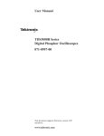
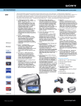
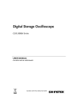
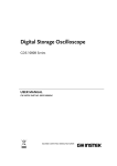
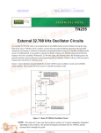
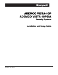
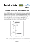
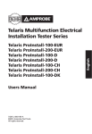
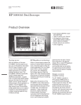
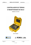
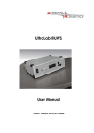
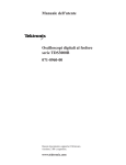
OSCILLOSCOPE
GUIDE
Tektronix TDS3000 Series
Department of
Electrical & Computer
Engineering
Tektronix TDS3000 Series Oscilloscope Guide v1.1
Portland State University
Contents
1 – INTRODUCTION ....................................................................................................... 2
2 –OSCILLOSCOPE OVERVIEW ................................................................................... 2
3 – INSTRUMENT FRONT PANEL ................................................................................. 3
► Power Switch.......................................................................................................................... 3
► Floppy Disk Drive.................................................................................................................... 3
► Hard Copy Button................................................................................................................... 3
► General Purpose Knob ........................................................................................................... 3
► LCD Screen ............................................................................................................................. 4
► Bottom-screen and Side-screen Menu Buttons..................................................................... 4
► VERTICAL Section Controls ..................................................................................................... 5
► HORIZONTAL Section Controls ............................................................................................... 6
► TRIGGER Section Controls ...................................................................................................... 7
► ACQUIRE Section Controls ..................................................................................................... 8
► MENU Controls....................................................................................................................... 8
► Input Connectors.................................................................................................................... 9
4 – PASSIVE PROBES ................................................................................................. 10
5 – SIMPLIFIED MEASUREMENT PROCEDURE ........................................................ 13
6 – SAVING WAVEFORMS .......................................................................................... 14
APPENDIX 1 – SPECIFICATIONS ............................................................................... 15
APPENDIX 2 – REFERENCES ..................................................................................... 15
1
Tektronix TDS3000 Series Oscilloscope Guide v1.1
Portland State University
1 – Introduction
This guide provides instructions for operating the Tektronix TDS3000 Series Digital Phosphor
Oscilloscopes. These are some features of various models1 in the product line:
•
100 to 500 MHz bandwidth
•
Up to 5 GS/s sample rate
•
2 or 4 channels
•
Full color LCD with graphical user interface
•
Serial, GPIB, and LAN I/O for data transfer and control
•
Built-in automated measurements
Copyright © Tektronix, Inc.
2 –Oscilloscope Overview
An oscilloscope is an instrument that measures a voltage signal and displays a graph of how the signal
varies over time. The vertical axis of the graph is the voltage, while the horizontal axis is time. Important
signal characteristics can be extracted from the graph, such as the shape and amplitude of the signal,
the frequency or period of a repetitive waveform, and the amount of noise or distortion.
A probe is used to connect the circuit being tested to the inputs of the oscilloscope. Each input, or
channel, can independently measure a signal. In a digital oscilloscope, an analog-to-digital converter
samples the input voltage signal and converts the analog values to digital form. The sampling is
performed repeatedly as part of the time sweep. The scope processes the incoming data and displays it
on the built-in monitor screen as a continuously updated graph of voltage versus time.
Important specifications of a digital oscilloscope include:
•
Bandwidth – Specifies the highest signal frequency that can be accurately measured
•
Sample rate – Determines how often the input signal can be sampled (samples per second)
•
Number of channels – Determines how many independent signals can be measured simultaneously
The front panel of a typical digital oscilloscope has these control sections:
•
Vertical – Adjusts the vertical (voltage) scaling and positioning of the waveform
•
Horizontal – Controls the horizontal (time) scaling and positioning of the waveform
•
Trigger – Provides a way to stabilize the display of repetitive signals on the screen
•
Acquisition – Controls how the input signal is acquired or sampled
1
The TDS3034B model has a 300 MHz bandwidth, 2.5 GS/s sampling rate, and four analog input channels.
2
Tektronix TDS3000 Series Oscilloscope Guide v1.1
Portland State University
3 – Instrument Front Panel
Figure 1: Tektronix TDS3000 series front panel - Copyright © Tektronix, Inc.
► Power Switch
The power switch turns the oscilloscope on or off.
► Floppy Disk Drive
The oscilloscope has a built-in 3.5” 1.44 MB floppy disk drive2. Oscilloscope setups and waveform data
can be saved to or recalled from a formatted disk that is inserted in the drive.
► Hard Copy Button
Pushing this button saves the waveform. Depending on how the button is configured, the waveform can
either be stored as a file on a floppy disk or sent to an attached printer.
► General Purpose Knob
The multipurpose knob is used to navigate the screen, select an item, or change a setting.
2
TDS3000, 3000A and 3000B models only. Later 3000C models have a USB drive port instead.
3
Tektronix TDS3000 Series Oscilloscope Guide v1.1
Portland State University
► LCD Screen
The screen shows a graph of the signal that is measured on an input channel. The oscilloscope provides
controls for making individual channels either active (waveform is displayed on the screen) or inactive
(waveform is omitted).
Trigger
Status
RUN/STOP
Status
Graticle
Divisions
Waveform
Submenu
options
Zero
Reference
Marker
Horizontal Scale
(time/div)
Vertical Scale
(voltage/div)
Trigger
Settings
Channel
Indicator
Menu options
Each channel is color coded: CH1=yellow, CH2=blue, CH3=purple, CH4=green
The main graph area is divided into a grid to aid in reading the amplitude and timing of the waveforms.
Dotted grid lines represent the major divisions on each axis. The vertical axis has units of voltage, while
the horizontal axis has units of time.
► Bottom-screen and Side-screen Menu Buttons
The TDS3000 series support an on-screen menu for accessing various oscilloscope functions that are not
assigned to a dedicated button.
If an oscilloscope function requires menus, then they are displayed on the bottom edge of the LCD
screen. When a menu option is selected, additional submenu options may appear on the right edge of
the screen. The content of the menus will vary depending on the current function.
The actual menu buttons are located on the plastic bezel that surrounds the LCD. By pressing a button,
the menu item associated with the button will be selected. A dedicated MENU OFF button turns off the
on-screen menus.
4
Tektronix TDS3000 Series Oscilloscope Guide v1.1
Portland State University
► VERTICAL Section Controls
The vertical section adjusts the vertical (voltage) configuration, scaling, and positioning of the waveform.
Each channel has its own independent vertical settings.
Dedicated Controls
CH 1, CH 2, CH 3, CH 4 CHANNEL SELECTION buttons
All of the available oscilloscope inputs (i.e., channels) share a single set of controls. The channel
selection buttons determine which channel is currently chosen to be controlled. When a channel
button is pressed, the associated channel becomes active and appears on the screen.
VERTICAL POSITION knob
This knob moves the position of the currently selected waveform either up or down on the LCD
screen. It does not change the vertical scale.
VERTICAL SCALE knob
This knob adjusts the vertical scale (size) of the currently selected waveform. The vertical voltage
scale is specified in units of volts per division (V/div).
Example: If the scale is 2 V/div, then each major division on the vertical axis represents a 2 V span.
OFF button
The OFF button removes the currently selected waveform from the display.
MENU button
The MENU button activates additional on-screen menus for the vertical section.
Menu-based Controls
[Coupling]
This selects the channel’s input coupling (DC, AC, or Ground).
•
•
•
DC – Allows both AC and DC signals to get through (default)
AC – Filters out any DC signals, so only the AC variation is displayed
Ground – Temporarily replaces the waveform with a 0 V flat reference line
It is also used to select the channel’s input resistance (1 MΩ, 50 Ω).
•
•
1 MΩ – Used for typical voltage measurements (default)
50 Ω – Used to match impedance with other 50 Ω systems
[Invert]
This button inverts the polarity of the selected waveform.
[Bandwidth]
This controls the oscilloscope bandwidth (Full, 150 MHz, 20 MHz).
[Fine Scale]
This enables finer adjustment of the vertical scale using the general purpose knob.
[Position]
This controls the waveform’s vertical position using the general purpose knob.
[Offset]
This adjusts the waveform’s vertical offset using the general purpose knob.
[Probe Setup]
For probes that do not use the TekProbe interface, this option allows the probe
attenuation factor to be changed using the general purpose knob. (1mX to 1kX full
range, 1X or 10X typical)
5
Tektronix TDS3000 Series Oscilloscope Guide v1.1
Portland State University
► HORIZONTAL Section Controls
The horizontal section adjusts the horizontal (time) scaling and positioning of the waveform. All
channels share the same horizontal settings.
Dedicated Controls
HORIZONTAL POSITION knob
This knob moves the position of the currently selected waveform either left or right on the LCD
screen. It does not change the horizontal scale.
HORIZONTAL SCALE knob
This knob adjusts the horizontal scale of the currently selected waveform. It does not change the
horizontal position. The horizontal time scale is specified in units of time per division (e.g., ms/div).
Example: If the scale is 5 ms/div, then each major division on the horizontal axis represents 5 ms.
DELAY button
The DELAY button is used to delay signal acquisition relative to the triggering event by using the
HORIZONTAL POSITION knob.
ZOOM button (looks like a magnifying glass)
The ZOOM button magnifies the currently selected waveform along its horizontal axis. When in
zoom mode, the HORIZONTAL SCALE knob controls the magnification factor, while the HORIZONTAL
POSITION knob selects the portion of the waveform that should be magnified.
6
Tektronix TDS3000 Series Oscilloscope Guide v1.1
Portland State University
► TRIGGER Section Controls
To show a stable image of a repeating waveform on the screen, the oscilloscope needs to acquire the
signal at the same point on the waveform during each sweep. This is done by settng a threshold voltage
value that, when the measured signal crosses the threshold, causes the oscilloscope to initiate an
acquisition sweep. This threshold is called the “trigger level”. The trigger source can be either the input
signal itself or an external trigger signal.
Note: If the measured input signal never crosses the threshold because the level was set too high or too
low, the displayed waveform will be unstable and jitter erratically on the screen.
The TDS3000 series supports two triggers, which are known as the A trigger (default) and the B trigger
(optional).
Dedicated Controls
TRIGGER LEVEL knob
This knob adjusts the trigger level of the currently selected waveform. A horizontal line temporarily
appears on the screen to indicate the trigger level. The level should be adjusted until the waveform
appears stable on the screen.
SET TO 50% button
This button automatically sets the trigger level to 50% of the peak-to-peak amplitude of the source
trigger waveform.
FORCE TRIG button
The FORCE TRIG button manually causes a trigger event to occur, even if there is no input signal.
B TRIG button
This button provides a B trigger in addition to the existing A trigger.
MENU button
The MENU button activates on-screen menus for the trigger section.
Menu-based Controls
These are the menu options for edge triggering:
[Source]
This selects the edge trigger signal source (input channel, AC line, external signal)
[Coupling]
This allows selection of the coupling (DC, HF Reject, LF Reject, Noise Reject).
[Slope]
This determines whether to trigger on the rising or falling edge of a signal.
[Level]
This is used to modify the trigger threshold voltage level.
7
Tektronix TDS3000 Series Oscilloscope Guide v1.1
Portland State University
► ACQUIRE Section Controls
The acquire section controls how signals are acquired and processed.
Dedicated Controls
RUN/STOP button
This button allows the user to start and stop the continuous waveform acquisition.
SINGLE SEQ button
This enables a single-sequence acquisition of a signal, after which the acquisition stops.
AUTOSET button
This button automatically adjusts the VERTICAL, HORIZONTAL, and TRIGGER controls to acquire a
usable display. The controls may need further manual adjustment for best results.
WAVEFORM INTENSITY knob
This knob adjusts the intensity of the displayed waveform. At maximum intensity, the view is like a
standard digital oscilloscope. At medium intensity, the view simulates an analog oscilloscope.
MENU button
The MENU button activates on-screen menus for the acquire section.
► MENU Controls
The MENU controls activate on-screen menus for performing various functions. The menu appears at
the bottom of the screen, while submenu options appear on the right side of the screen.
MEASURE
This button is used to access the oscilloscope’s built-in automated measurements.
Some examples include finding the amplitude and frequency of a signal, finding the
min/max values, and computing rise and fall times.
SAVE/RECALL
This is used to save or recall oscilloscope setups and waveforms to nonvolatile
memory or to the floppy disk. Measured waveform data can be saved as a Mathcad
data file, or as a CSV file that can be imported into a spreadsheet.
QUICKMENU
This bypasses standard menus to provide quick access to basic oscilloscope
operations.
CURSOR
This is used for making amplitude and time measurements. For example, vertical or
horizontal bars can be superimposed on the screen to mark key points on waveforms.
DISPLAY
This button controls display options such as persistence, format, and contrast.
UTILITY
This button gives access to system utilities such as setting the hard copy parameters,
adjusting the system date/time, and running diagnostics.
Note: The buttons marked with a star are very useful for quickly setting up the oscilloscope.
8
Tektronix TDS3000 Series Oscilloscope Guide v1.1
Portland State University
► Input Connectors
External probes are attached to the female BNC input connectors on the front panel of the oscilloscope.
Each input connector is surrounded by the TekProbe interface ring. If a probe supports the interface, the
oscilloscope autodetects the probe attenuation factor (e.g., 1X or 10X), the coupling, and the input
resistance. If the probe does not use the interface, then these settings must be set manually.
9
Tektronix TDS3000 Series Oscilloscope Guide v1.1
Portland State University
4 – Passive Probes
A typical passive probe consists of a cable with a male BNC connector on one end and a retractable hook
tip (or a pointed tip) with ground clip on the other. The BNC side attaches to one of the oscilloscope’s
inputs, while the probe tip is attached to a measurement point in the test circuit.
The probe tip is where the voltage signal enters the probe and is then carried through the cable to the
center pin of the BNC connector. The ground clip provides the ground reference from the test circuit to
the outer shield of the BNC connector.
Retractable Hook
Tip Adapter
Clip-on Ground
Lead
Probe
This end
attaches to the
oscilloscope
input
Cable
Adjustment
Tool
Figure 2: General purpose voltage probe with accessories – Copyright © Tektronix, Inc.
Circuit
Being
Measured
Probe
Cable
Oscilloscope
Input
Rprobe
9 MΩ
Tip
Ccable
Cprobe
Rin
1 MΩ
Cin
20 pF
GND
A 10X probe uses a 9 MΩ series
resistor to increase the total
input resistance “seen” by the
measured device to 10 MΩ.
All cables have some
amount of shunt
capacitance.
Input
TDS2000 series scopes
have a fixed input
resistance of 1 MΩ.
Input
Figure 3: Simplified circuit model of a 10X probe connected to an oscilloscope’s input channel
(For a 1X probe, Rprobe and Cprobe are omitted and replaced by a direct wire path.)
10
Tektronix TDS3000 Series Oscilloscope Guide v1.1
Portland State University
These are some important characteristics of a probe:
•
Bandwidth – This is the highest frequency signal that the probe can accurately pass through to the
oscilloscope for measurement. A common metric is the frequency at which the measured signal
amplitude has decreased by 3 dB from the original value.
•
Attenuation – The attenuation factor determines how much the probe reduces the amplitude of the
input signal before it enters the oscilloscope. Typical probes are either 1X (no attenuation at all) or
10X (amplitude is divided by 10). Some probes support manual switching between 1X and 10X
modes. Attenuation also affects the total input resistance that is “seen” by the circuit being tested.
Note: The attenuation factor setting in the vertical section of the oscilloscope should be changed to
match the attenuation factor of the probe. The displayed V/div value will be incorrect if the
factors do not match.
•
Loading Effect – As seen in the schematic diagram, the probe and oscilloscope are attached in
parallel with the test circuit. As a consequence, the measured voltage is influenced not only by the
circuit’s intrinsic characteristics, but also by the components of the probe and oscilloscope. In
particular, the effective input resistance and capacitance of the combined probe and oscilloscope
system affects the accuracy and fidelity of the voltage measurement.
Table 1: Typical characteristics of common probes
Probe
Description
Attenuation
Ratio
Total Input
Resistance
Total Input
Capacitance
10X probe
10:1
10 MΩ
1 to 25 pF
1X probe
1:1
1 MΩ
100 to 200 pF
Best Used For
Low-to-high amplitude
DC-to-high frequency
Very low-to-medium amplitude
DC-to-low frequency
For most measurements, the 10X probe is utilized because its high effective input resistance lessens
the load effect on the test circuit, and its low input capacitance allows higher frequencies to be
measured. On the other hand, the large attenuation factor makes measurements of very low
amplitude signals less accurate.
If the voltage level of the input signal is tiny, then a 1X probe may be a better choice because there
is no attenuation through the probe. However, the 1 MΩ input resistance imposes a larger loading
effect and the high input capacitance limits the frequency range.
11
Tektronix TDS3000 Series Oscilloscope Guide v1.1
Portland State University
Probe Compensation
Some probes have a built-in compensation network that can be adjusted to better match a probe’s
unique operating characteristics to the oscilloscope’s inputs. Use the following procedure to
compensate a probe:
1. Connect the probe to the desired input channel on the oscilloscope.
2. On the front panel of the oscilloscope, attach the probe’s tip to the Probe Comp terminal and the
probe’s ground lead to the chassis ground terminal. On the TDS3000 series, the terminals are
located by the Channel 2 input connector. PROBE COMP generates a 5 volt square wave at 1 kHz.
3. Push the AUTOSET button to acquire the test signal.
4. Use the probe’s adjustment tool to make the square wave have a flat top.
Over compensated
Under compensated
Properly compensated
Figure 4: Effects of probe compensation on a square wave
12
Tektronix TDS3000 Series Oscilloscope Guide v1.1
Portland State University
5 – Simplified Measurement Procedure
1. Before making any connections, verify that the test circuit will not produce voltage or current levels
that could damage the oscilloscope.
2. Turn on the oscilloscope. The instrument is more accurate if allowed to warm up for a while.
3. Choose probes that are appropriate for the measurement. Each channel requires a separate probe.
4. For each channel that will be used:
a. Attach the probe’s BNC connector to an input connector on the oscilloscope.
b. If necessary, configure the attenuation, coupling, and input resistance for the channel.
c. If the probe has a built-in compensation network, then compensate the probe.
(Perform compensation whenever a probe is connected to the oscilloscope for the first
time.)
d. Connect the probe to the test circuit. If you will be working with static-sensitive parts, then
wear a grounding strap before making the connections.
i. Attach the ground clip of the probe to a ground point in the circuit.
ii. Attach the probe tip to the voltage measurement point in the circuit.
5. If the test circuit is not turned on yet, then apply power to the circuit.
6. Adjust the oscilloscope’s controls to achieve a stable display of the waveform.
(The AUTOSET button can be used to get a reasonable initial display.)
7. Voltage measurements are done by counting the number of graticle divisions that a waveform spans
in the vertical direction. Timing measurements are performed similarly in the horizontal direction.
(The Measure button can be used to automate common signal measurements.)
13
Tektronix TDS3000 Series Oscilloscope Guide v1.1
Portland State University
6 – Saving Waveforms
After performing a measurement, it is often desirable to save the waveform for later reference. Data can
be saved as an image file (screen capture) or as a spreadsheet file (actual numeric data).
Note: The oscilloscope automatically generates consecutively numbered file names when saving files.
Saving as an image file
1. Insert a formatted 3.5” 1.44 MB floppy disk into the oscilloscope’s disk drive.
2. Press the UTILITY button on the front panel.
3. Select “System” from the lower menu. Keep pushing the same menu button until “Hard Copy” is
selected. The lower menu will change to show only hard copy options.
4. Select “Format” from the lower menu. The right submenu will now show a long list of available
printers and image file formats3. Cycle through the options to select the desired format.
5. Select “Options” from the lower menu. On the right submenu, select either “Landscape” or
“Portrait” for the orientation of the image.
6. Select “Ink Saver” from the lower menu. On the right submenu, select either “Off” (to capture the
screen colors as-is) or “On” (to change the background color from black to white).
7. Press the MENU OFF button to turn off the menus.
Once the hard copy options have been set, the current screen image can be captured to the floppy disk
at any time by pressing the Hard Copy button.
Saving as a spreadsheet file
1. Insert a formatted 3.5” 1.44 MB floppy disk into the oscilloscope’s disk drive.
2. Press the SAVE/RECALL button on the front panel.
3. Select the channel you want to save by pressing the appropriate Channel Selection button.
4. Select “Save Waveform ChX” from the lower menu.
5. Select “To File” from the right submenu.
6. To save the data as a spreadsheet file4: Select “Spreadsheet File Format” from the right submenu.
7. Select “Save ChX To Selected File” from the right submenu.
(It may take a while for the oscilloscope to finish writing the data to the floppy disk.)
Note: If the oscilloscope is connected to a standalone computer via a serial, GPIB, or LAN connection,
then the Tektronix OpenChoice Desktop application can be used to transfer the screen image or
waveform data directly to the computer.
3
Supported image file formats include TIFF, PCX, BMP, EPS, and PNG.
The spreadsheet file is stored in CSV (Comma Separated Values) text format. The resulting file can be imported
into a compatible program, such as MS Excel or MATLAB.
4
14
Tektronix TDS3000 Series Oscilloscope Guide v1.1
Portland State University
Appendix 1 – Specifications
Table 2: Manufacturer’s instrument specifications
Bandwidth
Channels
Sample Rate on Each Channel
Maximum Record Length
Vertical Resolution
Vertical Sensitivity (/div)
Vertical Accuracy
Maximum Input Voltage (1 MΩ)
Position Range
BW Limit
Input Coupling
Input Impedance Selections
Time Base Range
Time Base Accuracy
TDS3034B
300 MHz
4
2.5 GS/s
TDS3052B
500 MHz
2
5 GS/s
10 K points
9 bits
1 mV to 10 V
±2%
150 VRMS CAT I
±5 div
20, 150 MHz
20, 150 MHz
AC, DC, GND
1 MΩ in parallel with 13 pF or 50 Ω
2 ns/div to 10 s/div
2 ns/div to 10 s/div
20 ppm
Appendix 2 – References
[1]
Tektronix TDS3000B Series Data Sheet, Tektronix, Inc.
[2]
Tektronix TDS3000 & TDS3000B Operator Training Kit Manual (071-1051-00), Tektronix, Inc.
[3]
Tektronix TDS3000B Series Digital Phosphor Oscilloscopes Reference (071-0923-00),
Tektronix, Inc.
[4]
Tektronix TDS3000B Series Digital Phosphor Oscilloscopes User Manual (071-0957-04), Tektronix,
Inc.
[5]
XYZs of Oscilloscopes - Primer, Tektronix, Inc.
[6]
ABCs of Probes - Primer, Tektronix, Inc.
15