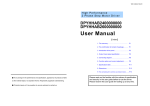
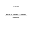
1
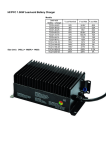
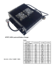
HF/PFC 1.5KW Lithium Battery Charger
Models
Lithium Battery
Vout Max
Iout Max
TCCH-H35-40
35V
40A
TCCH-H51-33
51V
33A
TCCH-H65-25
65V
25A
TCCH-H90-20
90V
20A
TCCH-H104-16
104V
16A
TCCH-H114-14
114V
14A
TCCH-H130-12
130V
12A
TCCH-H161-10
161V
10A
TCCH-H203-08
203V
8A
TCCH-H217-08
217V
8A
TCCH-H258-6A2
258V
6.2A
TCCH-H320-05
320V
5A
Charger Models
Size(mm):348(L) × 180(W) × 140(H)
N.W. (kg):6.33
I
HF/PFC On-board Charger (Lithium Battery Charger)
Product Summary & Application Scopes
The charger is applicable for various lithium batteries like LiFePO4, LiMn2O4 etc., It features light weight, small volume, stable
performance, high efficiency and reliable security etc., It can be switched automatically between the floating and balancing charging
and also has the protection functions of reverse connection, output short-circuit and overload and so on.
The charger is widely used for battery-charging cycles in electric vehicles such as electric forklift, golf cars, electric trucks, electric
tour bus, electric yacht, cleaning machines, or Uninterruptible Power Supply (UPS), solar energy, wind power dynamo and electric
communication system on the railway etc.
II Technical Target
AC Input Voltage Range
AC85V~AC265V
AC Input Frequency
45~65 Hz
AC Power Factor
≥0.98
Full Load Efficiency
≥93%
Mechanical Shock & Vibration Resistance Level
Conformance to SAEJ1378 Standard
Environmental Enclosure
IP46
Operating Temperature
-40℃~+55℃ (-104℉~+131℉)
Storage Temperature
-40℃~+100℃ (-104℉~+212℉)
Charging Control
Via CAN bus or ENABLE
III Protection Features
1. Thermal Self-Protection: When the internal temperature of the charger exceeds 75℃, the charging current will reduce
automatically. If it exceeds 85℃, the charger will shutdown protectively. When the internal temperature drops, it will resume charging
automatically.
2. Short-circuit Protection: When the charger encounters unexpected short-circuit, it will automatically stop to output. When fault
removes, the charger will re-start in 10 seconds.
3. Reverse Connection Protection: When the battery is polarity reversed, the charger will cut off the connection between the internal
circuit and the battery, and refuses to start. It can avoid any destroy.
4. Input Low-voltage & Over-voltage Protection: When the AC input Voltage is lower than 85V or higher than 265V, the charger will
shutdown protectively and automatically resume working with the voltage is normal again.
Ⅳ Appearance Labels
Please check carefully the labels on the casing of the charger before using in order to completing the transaction check the label on
the charger before using, it can provide some help for you to understand the performance and the specification of the charger.
i. Bar Code Label:
Attaches on the output terminal of the charger. For example, SN10071001
1007: Production batch number. 1001: Bar code number.
48-25: Hardware model
HD VER 1.6 : Version number from the manufacturer
ii. Model Label:take the model TCCH-H58V4-25A for example
INDUSTRIAL
58.4Vmax
BATTERY
CHARGER
Input: 100~240VAC 50/60Hz
14 / 8.1A
Output:
48V
25A@220VAC 48V
Battery:
LiFePO4
Model:
TCCH-H58V4-25A
24.5A@115VAC
16 cells
Environmental Enclosure: IP46
a) Input 100~240VAC 50/60Hz 14/8.1A: The rated input current is 14A at 115VAC and 8.1A at 220VAC;
b) Output 48V
115VAC.
25A@220VAC 48V
24.5A@115VAC: The maximum current is 25A at input 220VAC, and 24.5A at input
c) Will add “-CAN” after the model if the charger controlled by CAN module. E.g. “TCCH-H58V4-25A-CAN”.
iii. LED Label
It is the important symbol to evaluate whether the charger works normally.
Red-Green flash (one second interval)
Battery Disconnected
Red flash (three seconds interval)
Repair Battery
Red flash (one second interval)
<80% Charge Indicator
Yellow flash (one second interval)
>80% Charge Indicator
Green flash (one second interval)
100% Charge Indicator
Ⅴ Common Faults & Solutions
In case of the charging fails, please examine all the outside lines carefully to make sure that they are connected correctly. If circuits
failure have been excluded, you can check the failure code of charging LED and handle it according to the following table.
LED Flashing Sequence (One Cycle)
Indication
1
RG______
Wrong Battery
2
RGR_____
Overcharged
3
RGRG____
Battery Overheated
4
RGRGR___
Incorrect AC Input Voltage
5
RGRGRG__
External Thermal Sensor Fault
6
RGRGRGR_
Communication Interface Fault
7
GR______
Charger Overheated
8
G RG _____
Charger Relay Fault
9
G RG R____
Charger Itself Fault
Note: 1. R—red
G—green 2. “_” denotes one second pause
3. Above LED flashing sequence is one cycle; the LED will flash repeatedly if the fault has not been removed.
Solutions
▲ Wrong Battery: Verify the battery voltage range matching with charger or inspect the battery for damage.
▲ Overcharged: Confirm the battery capacity and the selected curve are matched or if the battery is defective.
▲ Battery Overheated: Check the temperature at the external thermal sensor. If overheated, the charger will start the battery
protection.
▲ Incorrect AC Input Voltage: Check that the AC input voltage is in accordance with the requirement.
▲ External Thermal Sensor Fault: Ensure connect the thermal sensor correctly.
▲ Communication Interface Fault: Make sure the communication have been correctly connected or if it is damaged.
▲ Charger Overheated: Check if the ambient temperature is too high or the ventilation is smooth.
▲ Charger Relay Fault: Repair. ▲ Charger Itself failure: Repair.
Connection Instruction for Control Interface
I. Charger’s Communication Connector
PIN
Description
1
ENABLE:
2
GND:
3
+12V:+12V internal power supply 12V (Load≤50mA)
4
LED - Red
5
LED - Green
6
RX: Serial Communication Receiver (for charger)
7
TX: Serial Communication Sender (for charger)
II. Security Tips
1. Do not allow the lead from any PIN to contact the battery positive or negative.
2. Never attempt to connect any two wires from the SP1312 connector that not be connected.
3. Applied power supply or load above 50mA to +12V PIN3 is forbidden.
4. Internal impedance of PIN1 (ENABLE) is 10K with allowable range 0~16V. Please connect a series
resistance of 10 K when controlling by an external 24V supply. (Refer to manufacturer first)
III. Charger’s Connection Instruction for Control Interface
◆ TC charger can have CAN communication control or ENABLE control modes. TCcharger company will configure either before delivery as per customer’s
requirement. Note that the control interface can not be active at the same time in different modes. The customer should select the appropriate control mode
according to the battery management system (BMS) type and the battery requirement.
BMS Category
BMS with CAN
Mode of Connection
Control mode No 1#
communication function
Brief Description
CAN communication Module
BMS controls the charging process by the commands
(Model: TC-619B V3.1)
sent from CANbus
Use normally open contacts of relay to control the
Relay control
charging enable wires.
Battery protector broad or
BMS without CAN
Closed=Enable, Open=Disable
Use optoelectronic coupled devices to control the
Control mode No 2#
Optocoupler device control
charging enable wires.
communication function
Use 2-5V (dividing by resistance) controlling the charging
2-5V control
enable wires and stop charging and be able to set up the
output current from 0% to 100% for the charger.
◆ Control mode No 1# : USING THE CAN COMMUNICATION CONTROL
1. The charger can be controlled by CAN communication when the BMS has functionality. The CAN
communication module is required (TC-619B V3.1) and can be connected with the BMS CANbus.
2. The customer should specify “CAN communication” protocol when ordering. Specified CAN ID,
CAN module type and CAN communication protocol supported are set up before delivery.
3. A Standard CAN module with cable length 225mm and the mating connector can be provided.
PIN 1 connects to CAN-L, PIN 3 connects to CAN-H. See below.
4. TC-619B V3.1 CAN communication module’s interface Diagram
5. SCHEMATIC
◆ Control mode No 2# : USING THE ENABLE CONTROL
1. Charging process: Constant current (this current is controllable) charging mode is applied first, then constant voltage charging when the
battery reaches the specified voltage point. The voltage does not increases in the constant voltage stage and the charge current will gradually
reduce. Charging ceases automatically when the current falls to a preset value (generally one tenth of maximum charging current). If ENABLE
signal is removed at any time, charging ceases.
2. The ENABLE/+12V wires can be used to control the charger by an ON/OFF signal from a battery management system.
3. Alternatively the voltage between ENABLE and GND can be used to linearly control the charger output current.
When it is above 2V, charger commences charging. Applying 2~5V can control the maximum output current.
Below 1.5V the charger will cease charging, re-applying above 2V will re-enable charging.
4. SCHEMATIC
5. ENABLE CONTROL THREE METHODS
▼ ENABLE CONTROL method 1: USING RELAY CONTROL
The charger provides +12V (red) and ENABLE(black) from 7-PIN connector. A relay can be connected with BMS according to the Schematic below. Charging is
controlled by connecting or disconnecting +12V and ENABLE. If ENABLE is disconnected, charging will cease. Upon re-connection, the charger will
recommence charging.
▼ ENABLE CONTROL method 2:
Optical-couple Control
Alternatively an Optical-coupling device can be connected with the BMS according to the Schematic below. Charging is controlled by connecting or
disconnecting +12V and ENABLE. If ENABLE is disconnected, charging will cease. Upon re-connection, the charger will recommence charging.
▼ ENABLE CONTROL method 3: USING 2-5V CONTROL
a. Control of charging current and stop charging can be controlled by altering the DC voltage on ENABLE (PIN 1). It is possible to control the the maximum
output current from 0% to 100% of the charger maximum capability. During the stop mode (<1.5V) if the voltage rises above 2V between ENALBE (PIN 1)
and GND(PIN2) charger will enter into working mode. In this working mode, when the control voltage is reduced under 1.5V the charger returns to the stop
mode. 2V~5V on ENABLE corresponds linearly to output current from 0% to 100%. For example,
When it is 2V between PIN 1 and PIN 2, maximum output current of the charger is 0; When 3V between them, it is 33% of the maximum
output current; When 4V between them, it’s 66% of it; When above 5V between them, it’s 100%.
b. If control only of the maximum charging current is required, use two resistors (R1, R2) to divide voltage and get a fixed DC voltage to ENABLE and the
charger operates at the corresponding current. Output current is determined by the voltage that divided by resistors. It’s also possible to use the external relay
control or optical-couple control. The output capacity of optical-couple should be more than 10mA and total value of two resistors should not be less than 1500
Ohms.
c. If the maximum charging current need to be altered at any time, it can be accomplished by changing the voltage between ENALBE and
GND. Generally, use PWM to drive the optical-couple. The output of optical-couple goes through RC filter and then connect to ENABLE.
The Schematic below shows another way of altering the voltage between ENABLE and GND using PWM output from the BMS.
IV. Descriptions
PIN
DEFINITION
1
ENABLE input
2
GND
3
+12V internal power supply
4
5
6
7
◆ Select PINs (1, 2, 3) , when using 2-5V to control.
PIN 1: Black
PIN 2: Green
PIN3: Red
◆ Select PINs (1, 3) , when using Relay and optocoupler to control.
PIN 1: Black
PIN 3: Red