1
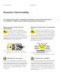
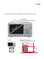
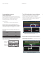
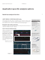
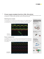
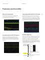
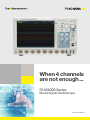
When 4 channels are not enough ... DLM4000 Series Mixed Signal Oscilloscope Bulletin DLM4000-01EN The DLM4000 is the world’s first 8 channel oscilloscope providing comprehensive measurement and analysis capabilities for embedded, automotive, power and mechatronics applications. Representing decades of experience in providing quality test and measuring tools, the DLM4000 is designed to satisfy the wide ranging needs of engineers today and in the future. The hardware optimized architecture in the DLM4000 enables measurements and signal processing to be carried out in real time. This means that signals from multiple channels are promptly captured and measurements are always performed and updated at high speed. The DLM4000 is: Versatile – The number of analog and digital channels, their flexibility and the wealth of measurement and analysis features enable the DLM4000 to solve the broadest range of test requirements. Intuitive – Via the straightforward interface, users can automatically or manually split the display to separate individual channel waveform while maintaining their full dynamic range. The details of signals can therefore be quickly analyzed irrespective of the number of channels in use. Capable – As intelligent control permeates more and more sectors of the industry from consumer electronics to industrial drives, the signals that engineers need to look at for testing become faster and more complex. The DLM4000 delivers the features and performance that engineers need in an advanced oscilloscope. Why choose Yokogawa Our passion for measurement Yokogawa believes that precise and effective measurement lies at the heart of successful innovation – and has focused its own R&D on providing the tools that researchers and engineers need to address their challenges both great and small. Our heritage Yokogawa has been developing measurement solutions for almost 100 years, consistently finding new ways to give R&D teams the tools they need to gain the best insights from their measurement strategies. Our oscilloscope design has been led by customers looking for ease-ofuse and functionality. Our commitment Yokogawa takes pride in its reputation for quality, both in the products we deliver – often adding new features in response to specific client requests – and the level of service and advice we provide to our clients, helping to devise measurement strategies for even the most challenging environments. Superior functionality DLM4000 series Superior functionality For today’s challenges in embedded, automotive, power and mechatronics. The DLM4000 – Eight-channel, 500 MHz bandwidth oscilloscope. Motor control & inverter circuit development Electronic control unit & mechatronic test The key to efficient and reliable highperformance electric motors is the modern inverter design, or ‘Intelligent Power Module’. Multi-channel, high-speed waveform measurement is an absolute necessity. Four channels are simply not enough. Boasting eight true analog inputs, the DLM4000 empowers today’s engineer with a convenient and comprehensive measurement system. Numerous I/O analog, digital, and serial-bus waveforms surrounding the Electronic Control Unit (ECU) must be measured. The DLM4000 offers ample channel-count and architecture to monitor eight analog channels and up to 24-bits of logic input while simultaneously performing protocol analysis such as UART, I2C, SPI, CAN, LIN and FlexRay. The DLM4000 can speed up the R&D process when four channels are not enough. 8ch 8ch Power Sensor Switch Example: 3 voltage & 3 current measurements of a 3-phase motor Measurement of the gate-drive signals of six IGBTs within the inverter 4ch Limitation of 4 ch scope Whole-system measurement is impossible with a fourchannel scope; the real difficulty is measuring the timing between IGBT gate signals within the inverter. Voltage and current measurements between 3 phases and the IO of the motor driver IC is a very challenging test with a fourchannel scope. The truly practical solution is an eightchannel MSO. Clock ECU Controller Reset Motor Actuator CAN/LIN/FlexRay UART/I2C/SPI Example: Analog I/O and serial bus controller signals Stringent real time test of digital waveforms in the analog domain. 4ch Limitation of 4 ch MSO The additional logic inputs of a four-channel MSO mixedsignal oscilloscope provides enough channels, but this method has a blind-spot. Digital waveform analysis using logic inputs alone cannot reveal anomalies such as voltage drift, noise, distortion or ringing, and measure risefall times. ECU testing requires stringent examination of all digital waveforms – and analog input channels are the best tool for the job. 4 5 The portable eight-channel DLM4000 is the daily instrument of choice. 12.1 inch LCD Easily observe eight waveforms h .1 2 1 Portable c in Modest 178 mm depth Half of the former model DL7480 178 mm 355 mm 6.6 kg Former model DL7480 Superior functionality DLM4000 series Long waveform memory Up to 250 MPoints Two fully independent zoom windows The two advantages of a long waveform memory are the abilities to capture for long periods of time and to maintain high sample rates. Thus achieving higher effective measuring bandwidths for all time base settings. Enabling two fully independent zoom windows allows users to analyze the cause and effect of abnormal behaviors over all input channels. Users can also view and compare the details and timing of different serial buses operating at different speeds. <Basic Formula> Measuring time = Memory length/Sample rate With the maximum memory installed (/M3 option), in single shot mode, a 10 kHz signal lasting for more than one hour can be captured. The same memory can capture a 200 millisecond signal at a sampling rate of 1.25 GS/s. Relationship between measuring time and sample rate in 250 Mpoint Sample rate 1.25 GS/s Details of waveform can be magnified Zoom 1 ×1000 Zoom 2 ×100000 Maximum measuring time 0.2 s 125 MS/s 2s 12.5 MS/s 20 s 1.25 MS/s 200 s 125 kS/s 2000 s 62.5 kS/s 5000 s Caution is needed when using an oscilloscope that does not have enough memory, which can cause lack of sample rate and will possibly fail to capture waveforms accurately. Detailed waveform measured for 50 seconds are shown in 50 milliseconds and 500 microseconds span. Advanced waveform search functions Single waveform acquisitions of up to 250 MPoints can be searched using various criteria. Sample rate is too low. Search result marked Searched part is displayed in the zoom area Sample rate is fairly high. Criteria: T > setting Waveform search using “State width” 6 7 History function Automatically capture and replay up to 50000 waveforms The DLM4000 can capture and replay up to 50000 individual acquisitions (/M3 option). These can be displayed one at a time or as an accumulation. Using the search and measurement functions, abnormal signals can therefore be quickly isolated, analyzed and precisely categorized without needing to carefully configure triggers to capture rare events. #1 #2 #3 #50000 History search function Search up to 50000 waveform history records based on detailed search parameters using the history search function. Accumulate display mode Extract abnormal waveform Place square zone and search Searching for waveforms that pass through or do not pass through a rectangular zone placed on screen. Replay function Automatically play back, pause, fast forward, and rewind waveform history records. Single acquisition display mode Application specific analysis options DLM4000 series Application specific analysis options Serial bus analysis function UART (RS232) /I2C/SPI/CAN/LIN/FlexRay Dedicated trigger and analysis options are available for various serial buses of both in-vehicle and embedded systems. A wide variety of trigger combinations can be set, including ID and Data combinations, which can also be combined with conventional edge triggers. Serial bus auto-setup saves time An intelligent serial bus auto-setup detects bit-rate and voltage threshold automatically and enables the DLM4000 to be quickly configured. 8 Related Accessories Differential probe PBDH1000 (701924) DC to1.0 GHz bandwidth1 MΩ, approximately 1.1 pF Maximum differential input voltage range: ±25 V Up to 4 buses simultaneously Analysis can be performed at high speed simultaneously on up to four different buses operating at different speeds. This is enhanced by the extensive search facilities, allowing the user to look for specific data in the very long memory. The dual-zoom facility means that different buses can be viewed and debugged alongside each other. Differential probe (701920) DC to 500 MHz bandwidth 100 kΩ, approximately 2.5 pF Maximum differential input voltage range: ±12 V CAN, LIN, SPI, I2C can be viewed simultaneously by using zoom. Logic probe PBL100/PBL250 (701988/701989) 100 MHz/250 MHz toggle frequency 1 MΩ, 10 pF/100 kΩ, 3 pF Four bus decode and list display 9 Power supply analysis function (/G3, /G4 option) The /G3 and /G4 options enable switching loss, joule integral (I2t), SOA (safe operating area), harmonics based on EN61000-3-2, and other power parameters to be measured and analyzed. Switching loss analysis The switching loss of the voltage and current input waveforms can be computed (U(t) × I(t)) over long time periods. The turn-on/off loss, the loss including the continuity loss, and the loss over many cycles of the 50 Hz/60 Hz power line can be calculated and analyzed. Related Accessories Differential probe PBDH0150 (701927) DC to 150 MHz 1000 Vrms/ ±1400 Vpeak Differential probe (701926) DC to 50 MHz 5000 Vrms/7000 Vpeak Switching loss and SOA analysis of power devices Power measurement The DLM4000 can also be used as a power meter by providing automated measurement of power parameters for up to two pairs of voltage and current waveforms, such as the active power, apparent power and power factor. These values can then be statistically processed and calculated. Current probe PBC100/PBC050 (701928/701929) DC to 100 MHz (701928) DC to 50 MHz (701929) 30 Arms Deskew correction signal source (701936) Power parameter measurement of three-phase motor Features and benefits DLM4000 series Features and benefits Waveform computation Logic signal measurement and analysis The DLM4000 provides powerful and flexible math functions such as arithmetic, filtering and FFT. Up to 4 math channels are available. The flexible MSO inputs are included as standard. This enables the DLM4000 to be converted to a 7 analog and 8 digital input MSO. With the /L16 option, up to 24 logic signals can be measured. Bus/State display and optional DA calculation function, which is useful for evaluating AD/ DA converters, are also provided. FFT analysis of high frequency noise Comprehensive waveform display (7 ch + 24 bits) User defined math (/G2, /G4 option) Reliable triggering Equations can be arbitrarily created using a suite of operators such as trigonometric and logarithmic operators, integration and differentiation, pulse width operators, phase measurement and digital to analog conversion. When just a specific event or abnormal waveform needs to be captured, the flexible and reliable triggering of the DLM4000 is the solution. In addition to basic trigger functions such as Edge, State, and Pulse Width – Advanced trigger types are provided, including Edge OR between multiple channels, Serial Bus trigger in which A combination of two bus signals is possible, or an A and B combination of different trigger types. Edge trigger Enhanced triggers Edge Edge OR Edge (qualified) State Pulse width State width Serial (optional) CAN/LIN/UART/I2C/SPI (standard) user defined NTSC/PAL/SDTC/HDTV/user defined TV F-V conversion of encoder pulse signal B triggers Force trigger A Delay B A to B (n) Dual bus (combination trigger of 2 serial busses) Force trigger manually 10 11 Automatic parameter measurement and statistical analysis 30 waveform parameters from a total of 29 different types can be displayed simultaneously with a high update rate. In addition to the basic statistical analysis of repetitively measured parameters, the Yokogawa original “cycle statistic” and “history statistic” measurement functions helps the advanced analysis of periodic mechatronic signals. To observe the fluctuations of measured parameters, it is possible to display them as trends. Period-to-period changes can then be easily seen. The variation of parameters can also be displayed as histograms thus providing a visual method of assessing them statistically. Automatic GO/NO-GO function The GO/NO-GO function can be used to test the results of parameter measurements, trigger conditions and other criteria and automatically save or print data, send an e-mail etc. Save time using unattended supervisory data acquisition. Variety of display formats Many types of display format are supported such as split, dual-zoom, XY, FFT, histogram etc. Action specified for NO-GO Buzzer Output to printer Save waveform data file E-mail transmission Thumbnails of saved files The image and file names are shown so that you can view screen image contents while copying or deleting files. A file can be enlarged to confirm the data. Thumbnails of saved files Trend of waveform parameters Abnormal waveform detected Thumbnail can be viewed full-size Built-in user’s manual View detailed graphical explanations of the oscilloscope’s functions by pressing the “?” key. Functions and operations can be shown on screen without having to consult the user’s manual. PC connectivity and software tools DLM4000 series PC connectivity and software tools 1000BASE-T/100BASE-TX/10BASE-T Hub or router * Hub or router * Sends waveform, screen, and settings data Remote control Mail transmission (GO/NO-GO action) Sends waveform, screen, and settings data Remote control USB Ethernet DLM4000 Supports USB: *DLM4000’s internal storage can be recognized by a PC as an external USB storage device. Transferring files is easy even when a USB thumb drive can’t be used. A comprehensive suite of software tools to support and complement complex measurement tasks. Free Trial version available XviewerLITE Xviewer Off-line waveform display and analysis Basic display and measurement Provides zooming, vertical cursors and data conversion to CSV format. Waveform monitoring on a PC Xwirepuller Advanced analysis Xviewer can display acquired waveforms, transfer files and control instruments remotely. In addition to simply displaying the waveform data, Xviewer features many of the same functions that the DLM4000 offers; zoom display, cursor measurements, calculation of waveform parameters, complex waveform math and FFT. Binary waveform data can easily be converted to CSV, Excel or Floating Point Decimal format. Data transfer to a PC Command control Custom software development The DLM4000 can be simply controlled using a PC and mouse via an Ethernet, USB, or GP-IB interface. When the software program starts, a simulation of the oscilloscope appears on the PC display. LabVIEW drivers MATLAB toolkit By using the LabVIEW driver written for the DLM4000, a developer can dramatically reduce the amount of work required to enable a PC to control the instrument from within the LabVIEW environment. The MATLAB® tool kit can be used to control the DLM4000 and to transfer data via GP-IB, USB or Ethernet from within MATLAB. Control libraries The TMCTL DLL (Dynamic Link Library) enables Microsoft Visual studio programs, such as Visual C++ and Visual Basic, to be quickly developed to communicate between the PC and the DLM4000. It supports GPIB, USB and Ethernet interfaces. Command line tool The DLTerm command line tool can be used with the TMCTL library to develop communication programs. Prototype code can be rapidly created to automate sequences of capture, measurement and analysis tasks before writing a fully custom software routine. Symbol editor Physical value symbol definition files for CAN serial bus analysis can be created and edited. CANdb files can also be imported. 12 Broad connectivity and easy control Broad connectivity and easy control 1 13 4 5 2 3 6 7 10 14 15 9 8 17 16 11 12 13 18 1 Dedicated Zoom Knob 10 Eight Analog Input Channels 2 Vertical Position and Scale Knob 11 1000 BASE-T Ethernet 3 Horizontal Position and Scale Knob 12 USB-PC connection terminal 4 Four-Direction Selector Button 13 External trigger output Select key moves the cursor up/down/left/right 5 Jog Shuttle and Rotary Knob 6 Dedicated Trigger Level Knob 7 USB peripheral connection terminal × 2 8 Logic input connector 16 bit (optional) 9 Channel 8, convertible to 8 bit Logic Input 14 External trigger input 15 RGB video output terminal 16 GO/NO-GO output terminal 17 Probe power supply terminal × 8 (optional) 18 GP-IB connection terminal (optional) Specifications DLM4000 series Models Trigger type, trigger source Model name Frequency bandwidth Input channels Edge CH1 to CH8, Logic, EXT, LINE Edge OR CH1 to CH8 Edge Qualified CH1 to CH8, Logic, EXT Analog Signal input State CH1 to CH8, Logic Input channels Analog input Pulse width CH1 to CH8, Logic, EXT CH1 to CH8 (CH8 is mutually exclusive with logic input Port L) State width CH1 to CH8, Logic Input coupling setting AC, DC, DC50 Ω, GND TV CH1 to CH8 Serial Bus I2C (optional) SPI (optional) UART (optional) FlexRay (optional) CAN (optional) LIN (optional) User defined DLM4038 350 MHz DLM4058 500 MHz Input impedance Analog input A triggers (Standard)8 analog channels or 7 analog channels + 8 bit logic (/L16 option) 8 analog channels + 16 bit logic or 7 analog channels + 24 bit logic 1 MΩ 50 Ω ±1.0%, approximately 20 pF ±1.0% (VSWR 1.4 or less, DC to 500 MHz) Voltage axis sensitivity setting range 1 MΩ 50 Ω 2 mV/div to 10 V/div (steps of 1-2-5) 2 mV/div to 500 mV/div (steps of 1-2-5) Max. input voltage 1 MΩ 50 Ω 150 Vrms Must not exceed 5 Vrms or 10 Vpeak Max. DC offset setting range 1 MΩ 50 Ω 2 mV/div to 50 mV/div 100 mV/div to 500 mV/div 1 V/div to 10 V/div 2 mV/div to 50 mV/div 100 mV/div to 500 mV/div AB triggers ±1 V ±10 V ±100 V ±1 V ±5 V A Delay B 10 ns to 10 s (Edge, Edge Qualified, State, Serial Bus) A to B(N) 1 to 109 (Edge, Edge Qualified, State, Serial Bus) Dual Bus Vertical-axis (voltage-axis) CH1 to CH8, Logic CH1 to CH8, Logic CH1 to CH8, Logic CH1 to CH8 CH1 to CH8 CH1 to CH8 CH1 to CH8 Serial Bus only Force trigger Force a trigger manually Trigger level setting range CH1 to CH8 ±4 div from center of screen DC accuracy*1 ±(1.5% of 8 div + offset voltage accuracy) Trigger level setting resolution CH1 to CH8 0.01 div (TV trigger: 0.1 div) Offset voltage accuracy*1 2 mV to 50 mV/div 100 mV to 500 mV/div 1 V to 10 V/div Trigger level accuracy*1 CH1 to CH8 ±(0.2 div + 10% of trigger level) Window Comparator Center/Width can be set on individual Channels from CH1 to CH8 ±(1% of setting + 0.2 mV) ±(1% of setting + 2 mV) ±(1% of setting + 20 mV) Frequency characteristics (−3 dB attenuation when inputting a sinewave of amplitude ±3 div) *1*2 DLM4038 DLM4058 1 MΩ (when using passive probe) 100 mV to 100 V/div 350 MHz 500 MHz 20 mV to 50 mV/div 300 MHz 400 MHz 50 Ω 10 mV to 500 mV/div 350 MHz 500 MHz 2 mV to 5 mV/div 300 MHz 400 MHz Display Display 12.1 inch TFT color liquid crystal display, 1024 × 768 (XGA) Functions Waveform Normal, Envelope, Average acquisition modes High Resolution mode Max. 12 bit (the resolution of the A/D converter can be improved equivalently by placing a bandwidth limit on the input signal) Isolation between channels Maximum bandwidth: −34 dB (typical value) Sampling modes Real time, interpolation, repetitive sampling Residual noise level*3 The larger of 0.4 mV rms or 0.05 div rms (typical value) Accumulation A/D resolution 8 bit (25 LSB/div) Max. 12 bit (in High Resolution mode) Select OFF, Intensity (waveform frequency by brightness), or Color (waveform frequency by color) Accumulation time: 100 ms to 100 s, Infinite Bandwidth limit FULL, 200 MHz, 100 MHz, 20 MHz, 10 MHz, 5 MHz, 2 MHz, 1 MHz, 500 kHz, 250 kHz, 125 kHz, 62.5 kHz, 32 kHz, 16 kHz, 8 kHz (can be set for each channel) Roll mode Enabled at 100 ms/div to 500 s/div (depending on the record length setting) Zoom function Two zooming windows can be set independently (Zoom1, Zoom2) Maximum sample rate Maximum record length (Points) Real time sampling mode Interleave OFF 1.25 GS/s Interleave ON 2.5 GS/s Zoom factor ×2 to 2.5 points/10 div (in zoom area) Scroll Auto Scroll Repetitive sampling mode 125 GS/s Search functions Edge, Edge Qualified, State, Pulse Width, State Width, I2C (option), SPI (option), UART (option), CAN (option), LIN (option), FlexRay (option) Repeat Single Single Interleave Standard 1.25 M 6.25 M 12.5 M /M1 6.25 M 25 M 62.5 M Max. data (record length 1.25 k Points) Standard: 2500, /M1: 10000, /M2: 20000, /M3: 50000 /M2 12.5 M 62.5 M 125 M History search Select Rect, Wave, Polygon, or Parameter mode /M3 25 M 125 M 250 M Replay function Automatically displays the history waveforms sequentially Display Specified or average waveforms ∆T, ∆V, ∆T & ∆V, Marker, Degree History memory Ch-to-Ch deskew ±100 ns Time axis setting range 1 ns/div to 500 s/div (steps of 1-2-5) Cursor Types Time base accuracy*1 ±0.002% Snapshot Currently displayed waveform can be retained on screen Computation and Analysis Functions Logic Signal Input Max, Min, P-P, High, Low, Amplitude, Rms, Mean, Sdev, IntegTY+, IntegTY, +Over, −Over, Pulse Count, Edge Count, V1, V2, ∆T, Freq, Period, Avg Freq, Avg Period, Burst, Rise, Fall, +Width, −Width, Duty, Delay Number of inputs Standard 8 bit × 1 Port L (mutually exclusive with CH8 input) /L168 bit × 3 Port L (mutually exclusive with CH8 input), Port A, Port B Parameter measurement Statistical computation Max, Min, Mean, σ, Count of parameters Maximum toggle frequency*1 Model 701988: 100 MHz, Model 701989: 250 MHz Compatible probes 701988, 701989 (8 bit input) (701980, 701981 are available) Min. input voltage 701988: 500 mVp-p, 701989: 300 mVp-p Input range Model 701988: ±40 V, Model 701989: threshold ±6 V Max. nondestructive input voltage ±40 V (DC + ACpeak) or 28 Vrms (when using 701989) Statistics modes Continuous, Cycle, History Trend/Histogram display Up to 2 trend or histogram display of specified wave parameters of wave parameters Computations (MATH) +, −, ×, Filter (Delay, Moving Avg, IIR Lowpass, IIR Highpass), Integ, Count (Edge, Rotary), user defined math (optional) Threshold level setting range Model 701988: ±40 V (setting resolution of 0.05 V) Model 701989: ±6 V (setting resolution of 0.05 V) Computable no. of traces 4 (Math1 to Math4) Input impedance 701988: Approx. 1 MΩ/approx. 10 pF 701989: Approx. 100 kΩ/approx. 3 pF Max. computable memory length Standard: 6.25 MPoints, /M1: 25 MPoints, /M2: 62.5 MPoints, /M3: 125 MPoints Maximum sampling rate 1.25 GS/s Reference function Up to 4 traces (REF1/REF4) of saved waveform data can be displayed and analyzed Action-on-trigger Actions: Buzzer, Print, Save, Mail GO/NO-GO Modes: Rect, Wave, Polygon, Parameter Actions: Buzzer, Print, Save, Mail XY Displays XY1, to XY4 and T-Y simultaneously FFT Number of points: 1.25 k, 12.5 k, 25 k, 125 k, 250 k Window functions: Rectangular, Hanning, Flat-Top FFT Types: PS (LS, RS, PSD, CS, TF, CH are available with /G2 or /G4 option) Histogram Displays a histogram of acquired waveforms Maximum record length (Points) Repeat Single Standard 1.25 M 6.25 M 12.5 M /M1 6.25 M 25 M 62.5 M /M2 12.5 M 62.5 M 125 M /M3 25 M 125 M 250 M Triggers Trigger modes Single Interleave (A, B) Auto, Auto Level, Normal, Single, N-Single 14 User-defined math (/G2 and /G4 options) The following operators can be arbitrarily combined in equations: +, −, ×, /, SIN, COS, TAN, ASIN, ACOS, ATAN, INTEG, DIFF, ABS, SQRT, LOG, EXP, LN, BIN, DELAY, P2 (power of 2), PH, DA, MEAN, HLBT, PWHH, PWLL, PWHL, PWLH, PWXX, FV, DUTYH, DUTYL, FILT1, FILT2 The maximum record length that can be computed is the same as the standard math functions. Power supply analysis (/G3 and /G4 options) Power analysis For Pwr1 and Pwr2, selectable from 4 analysis types. Deskweing between the voltage and current waveforms can be executed automatically. Switching loss Measurement of total loss and switching loss, power waveform display, Automatic measurement and statistical analysis of power analysis items (Wp, Wp+, Wp−, Abs. Wp, P, P+, P−, Abs.P, Z) SOA analysis by X-Y display, using voltage as X axis, and Safety operation area current as Y axis is possible 15 Harmonic analysis Power Measurement Basic comparison is possible with following standard Harmonic emission standard IEC61000-3-2 edition 2.2, EN61000-3-2 (2000), IEC61000-4-7 edition 2 Analyzable no. of frames 100000 frames max. Analysis results displays Analysis no., time from trigger position (Time (ms)), Frame type, ID, DLC, Data, CRC, presence/absence of Ack, information Auxiliary analysis functions Data search and field jump functions Analysis result save function Analysis list data can be saved to CSV-format files LIN Bus Signal Analysis Functions (/F4 and /F6 Options) Applicable bus LIN Rev. 1.3, 2.0, 2.1 Analyzable signals CH1 to CH8, M1 to M4 Bit rate 19.2 kbps, 9.6 kbps, 4.8 kbps, 2.4 kbps, 1.2 kbps User defined (an arbitrary bit rate from 1 kbps to 20 kbps with resolution of 10 bps) LIN bus Trigger modes Break Synch, ID/DATA, ID OR, and ERROR trigger Auto setup function Auto setting of bit rate, threshold value, time axis scale, voltage axis scale, and display of analysis results Analyzable no. of frames 100000 frames max. Joule integral Joule integral (I2t) waveform display, automatic measurement and statistical analysis is possible Analysis results displays Analysis no., time from trigger position (Time (ms)), ID, ID-Field, Data, CheckSum, information Automated measurement of power parameters for up to four pairs of voltage and current waveforms. Values can be statistically processed and calculated. Auxiliary analysis functions Data search and field jump functions Analysis result save function Analysis list data can be saved to CSV-format files Measurement Urms, Umn, Udc, Urmn, Uac, U+pk, U−pk, Up−p, Irms, parameters Imn, Idc, Irmn, Iac, I+pk, I−pk, Ip−p, P, S, Q, Z, λ, Wp, Wp+, Wp−, Abs.Wp, q, q+, q−, Abs.q, Avg Freq (voltage, current) FlexRay Bus Signal Analysis Functions (/F5 and /F6 Options) Applicable bus FlexRay Protocol Version 2.1 I2C Bus Signal Analysis Functions (/F2 and /F3 Options) Analyzable signals CH1 to CH8, M1 to M4 Applicable bus I2C bus Bus transfer rate: 3.4 Mbit/s max. Address mode: 7 bit/10 bit Bit rate 10 Mbps, 5 Mbps, 2.5 Mbps SM bus Complies with System Management Bus FlexRay bus Trigger modes Frame Start, Error, ID/Data, ID OR Analyzable signals CH1 to CH8, Logic input, or M1 to M4 Auto setup function I2C Trigger modes Every Start, Address & Data, Non-Ack, General Call, Start Byte, HS Mode Auto setting of bit rate, threshold value, time axis scale, voltage axis scale, and display of analysis results Analysis results displays Analysis no., time from trigger position (Time (ms)),1st byte address, 2nd byte address, R/W, Data, Presence/absence of ACK, information Analyzable no. of frames 5000 frames max. Analysis results displays Auto setup function Auto setting of threshold value, time axis scale, voltage axis scale, and display of analysis results Analysis no., time from trigger position (Time(ms)), Segment (Static or Dynamic), Indicator, FrameID, PayLoad length, Cycle count, Data, Information Auxiliary analysis function Data search Analyzable no. of data 300000 bytes max. Analysis result save function Analysis list data can be saved to CSV-format files Search function GP-IB (/C1 Option) Searches data that matches specified address pattern, data pattern, and acknowledge bit condition Analysis results save function Analysis list data can be saved to CSV-format files SPI Bus Signal Analysis Functions (/F2 and /F3 Options) Trigger types 3 wire, 4 wire After assertion of CS, compares data after arbitrary byte count and triggers. Analyzable signals CH1 to CH8, Logic input, M1 to M4 Byte order MSB, LSB Auto setup function Auto setting of threshold value, time axis scale, voltage axis scale, and display of analysis results Analyzable no. of data 300000 bytes max. Decode bit length Specify data interval (1 to 32 bits), decode start point, and data length Analysis results displays Analysis no., time from trigger position (Time (ms)), Data 1, Data 2 Auxiliary analysis functions Data search function Analysis result save function Analysis list data can be saved to CSV-format files UART Bus Signal Analysis Functions (/F1 and /F3 Options) Electromechanical specifications Conforms to IEEE std. 488-1978 (JIS C 1901-1987) Protocol Conforms to IEEE std. 488.2-1992 Auxiliary Input Rear panel I/O signal External trigger input/output, GO/NO-GO output, video output Probe interface terminal 8 terminals (front panel) Probe power terminal 8 terminals (side panel), (/P8 option) Internal Storage (Standard model /C8 Option) Capacity Standard: Approx. 1.8 GB, /C8 option: Approx. 7.2 GB Built-in Printer (/B5 Option) Built-in printer 112 mm wide, monochrome, thermal USB Peripheral Connection Terminal Connector USB type A connector × 2 (front panel) Electromechanical specifications USB 2.0 compliant Supported transfer standards Low Speed, Full Speed, High Speed Supported devices USB Mass Storage Class Ver. 1.1 compliant mass storage devices USB HID Class Ver.1.1 compliant mouse, keyboard Bit rate 1200 bps, 2400 bps, 4800 bps, 9600 bps,19200 bps, user defined (an arbitrary bit rate from 1 k to 10 Mbps with resolution of 100 bps) Analyzable signals CH1 to CH8, logic input, or M1 to M4 Data format Select a data format from the following 8 bit (Non Parity), 7 bit Data + Parity, 8 bit + Parity UART Trigger modes Every Data, Data, Error (Framing, Parity) Supported transfer standards High Speed, Full Speed Auto setup function Auto setting of bit rate, threshold value, time axis scale, voltage axis scale, and display of analysis results Supported class USBTMC-USB488 (USB Test and Measurement Class Ver. 1.0) Ethernet Analyzable no. of frames 300000 frames max. Connector RJ-45 connector × 1 Analysis results displays Analysis no., time from trigger position (Time(ms)), Data (Bin, Hex) display, ASCII display, and Information. Transmission methods Ethernet (1000BASE-T/100BASE-TX/10BASE-T) Supported services Server: FTP, HTTP, VXI-11 Client: FTP, SMTP, SNTP, LPR, DHCP, DNS Auxiliary analysis functions Data search Analysis result save function Analysis list data can be saved to CSV-format files USB-PC Connection Terminal Connector USB type B connector × 1 Electromechanical specifications USB 2.0 compliant General Specifications Rated supply voltage 100 to 240 VAC Rated supply frequency 50 Hz/60 Hz CAN version 2.0A/B, Hi-Speed CAN (ISO11898), Low-Speed CAN (ISO11519-2) Maximum power consumption 250 VA (when printer is used) Analyzable signals CH1 to CH8, M1 to M4 External dimensions 426 (W) × 266 (H) × 178 (D) mm (when printer cover is closed, excluding protrusions) Bit rate 1 Mbps, 500 kbps, 250 kbps, 125 kbps, 83.3 kbps, 33.3 kbps User defined (an arbitrary bit rate from 10 kbps to 1 Mbps with resolution of 100 bps) Weight Approx. 6.6 kg, With no options Operating temperature range 5˚C to 40˚C CAN Bus Signal Analysis Functions (/F4 and /F6 Options) Applicable bus CAN bus Trigger modes SOF, ID/DATA, ID OR, Error, Message and signal (enabled when loading physical values/symbol definitions) Auto setup function Auto setting of bit rate, threshold value, time axis scale, voltage axis scale, and display of analysis results *1Measured under standard operating conditions after a 30-minute warm-up followed by calibration. Standard operating conditions: Ambient temperature: 23˚C ±5˚C Ambient humidity: 55 ±10% RH Error in supply voltage and frequency: Within 1% of rating *2 Value in the case of repetitive phenomenon. The frequency bandwidth of a single-shot phenomenon is the smaller of the two values, DC to sampling frequency/2.5 or the frequency bandwidth of the repetitive phenomenon. *3When the input section is shorted, the acquisition mode is set to Normal, accumulation is OFF, and the probe attenuation is set to 1:1. Model and Suffix code Logic probes Model DLM4038*1 DLM4058*1 Power cord Model Product 701988 Logic probe (PBL100) 701989 Logic probe (PBL250) Option -D -F -Q -R -H -N -HE -HC -HK -HG -HF -HL -HS /L16 /B5 /M1*2 /M2*2 /M3*2 /P8*7 /C1 /C8 /G2*4 /G3*4 /G4*4 /F1*5 /F2*5 /F3*5 /F4*6 /F5*6 /F6*6 /E1*7 /E2*7 /E3*7 Description Mixed Signal Oscilloscope: 8 ch, 350 MHz Mixed Signal Oscilloscope: 8 ch, 500 MHz UL/CSA standard VDE standard BS standard AS standard GB standard NBR standard English Message and Panel Chinese Message and Panel Korean Message and Panel German Message and Panel French Message and Panel Italian Message and Panel Spanish Message and Panel Logic 16bit Built-in printer Memory expansion During continuous measurement: 6.25 Mpoints; Single mode: 25 Mpoints (when interleave mode ON: 62.5 Mpoints) Memory expansion During continuous measurement: 12.5 Mpoints; Single mode: 62.5 Mpoints (when interleave mode ON: 125 Mpoints) Memory expansion During continuous measurement: 25 Mpoints; Single mode: 125 Mpoints (when interleave mode ON: 250 Mpoints) Eight probe power connectors GP-IB Interface Internal storage (7.2 GB) User defined math Power supply analysis function Power supply analysis function (includes /G2) UART trigger and analysis I2C + SPI trigger and analysis UART + I2C + SPI trigger and analysis CAN + LIN trigger and analysis FlexRay trigger and analysis FlexRay + CAN + LIN trigger and analysis Four additional 701939 probes (8 in total) Attach four 701946 probes*8 Attach eight 701946 probes*8 Standard Main Unit Accessories Power cord (1 set), Passive probe 701939 (500 MHz, 1.3 m)*9 4 set, Protective front cover (1 set), Soft carrying case for probes (1 set), Printer roll paper (for /B5 option) 1 roll, Rubber leg cap (1 set), User’s manuals*10 *1: Logic probes are not included. Please order the accessory logic probe 701988/701989 sold separately. *2 to 6: Only one of these can be selected at a time. *7: Specify this option when using current probes or differential probes that don't support probe interface. *8: The 701939 probes are not included when this option is selected. *9: When /E1 option is selected, eight 701939 probes are included. When either /E2 or /E3 option is selected, no 701939 probe is included. *10:Start guide as the printed material, and User’s manuals as CD-ROM are included. Description 1 MΩ input resistance, max. toggle frequency 100 MHz, 8 inputs 100 kΩ input resistance, max. toggle frequency 250 MHz, 8 inputs Accessories (sold separately) Model 701939 701946 702906 701912 700939 701944 701945 701924 701927 701920 701922 700924 701921 701926 700925 701928 701929 701930 701931 701936 701919 B9988AE 366973 701968 701969-E 701969-J Product Passive probe*1 Miniature passive probe Passive probe (wide temperature range) Active probe (PBA1000) FET probe 100:1 high voltage probe 100:1 high voltage probe Differential probe (PBDH1000) Description 10 MΩ (10:1) /500 MHz/1.3 m 10 MΩ (10:1) /500 MHz/1.2 m 10 MΩ (10:1) /200 MHz/2.5 m −40°C to 85°C 1 GHz bandwidth, 100 kΩ (10:1), 0.9 pF 900 MHz bandwidth, 2.5 MΩ (10:1), 1.8 pF 400 MHz bandwidth, 1.2 m, 1000 Vrms 250 MHz bandwidth, 3 m, 1000 Vrms 1 GHz bandwidth, 1 MΩ (50:1), max. ±25 V 150 MHz bandwidth, max. ±1400 V, Differential probe (PBDH0150) 1 m extension lead 500 MHz differential probe 500 MHz bandwidth, max. ±12 V 200 MHz differential probe 200 MHz bandwidth, max. ±20 V 100 MHz differential probe 100 MHz bandwidth, max. ±1400 V 100 MHz differential probe 100 MHz bandwidth, max. ±700 V High voltage 50 MHz 50 MHz bandwidth, max. 5000 Vrms differential probe 15 MHz differential probe 15 MHz bandwidth, max. ±500 V Current probe (PBC100)*2 100 MHz bandwidth, max. 30 Arms 50 MHz bandwidth, max. 30 Arms Current probe (PBC050)*2 10 MHz bandwidth, max. 150 Arms Current probe*2 2 MHz bandwidth, max. 500 Arms Current probe*2 Deskew correction signal For deskew between voltage and current source Probe stand Printer roll paper GO/NO-GO cable Soft carrying case Rack mount kit for DLM4000 Rack mount kit for DLM4000 Round base, 1 arm One lot: 10 rolls, 10 m each GO/NO-GO signal output For DLM4000 EIA standard-compliant JIS standard-compliant *1: Please refer to DL Series Accessories brochure for 701939 adapters. *2: Current probes' maximum input current may be limited by the number of the probes used at a time. Accessory Software Model Product 701991 MATLAB tool kit 701992-SP01 Xviewer 701992-GP01 Description MATLAB plug-in software Viewer software (standard edition) Viewer software (MATH edition) External dimensions unit: mm 266 Language Suffix code Model 709820 Suffix code -G2 -G3 -G4 -F1 -F2 -F3 -F4 -F5 -F6 Description User defined math Power supply analysis function Power supply analysis function (includes G2) UART trigger and analysis I2C + SPI trigger and analysis UART + I2C + SPI trigger and analysis CAN + LIN trigger and analysis FlexRay trigger and analysis CAN + LIN + FlexRay trigger and analysis *: Separately sold license product (customer-installable). 426 9 Additional Option License for DLM4000* 13.4 178 23 [DLM is a registered trademark of Yokogawa Electric Corporation.] Any company’s names and product names appearing in this document are the registered trademarks or trademarks of their respective companies. NOTICE ● Before operating the product, read the user's manual thoroughly for proper and safe operation. This is a Class A instrument based on Emission standards EN61326-1 and EN55011, and is designed for an industrial environment. Operation of this equipment in a residential area may cause radio interference, in which case users will be responsible for any interference which they cause. YMI-KS-MI-SE01 YOKOGAWA METERS & INSTRUMENTS CORPORATION Global Sales Dept. /Phone: +81-422-52-6237 Facsimile: +81-422-52-6462 E-mail: [email protected] YOKOGAWA CORPORATION OF AMERICA YOKOGAWA EUROPE B.V. YOKOGAWA SHANGHAI TRADING CO., LTD. YOKOGAWA ELECTRIC KOREA CO., LTD. YOKOGAWA ENGINEERING ASIA PTE. LTD. YOKOGAWA INDIA LTD. YOKOGAWA ELECTRIC CIS LTD. YOKOGAWA AMERICA DO SUL LTDA. YOKOGAWA AUSTRALIA PTY. LTD. YOKOGAWA MIDDLE EAST & AFRICA B.S.C(c) Phone: +1-770-253-7000 Phone: +31-88-4641000 Phone: +86-21-6239-6363 Phone: +82-2-2628-3810 Phone: +65-6241-9933 Phone: +91-80-4158-6000 Phone: +7-495-737-7868 Phone: +55-11-5681-2400 Phone: +61-2-8870-1100 Phone: +973-17-358100 Subject to Change without notice. Copyright © 2012, Yokogawa Meters & Instruments Corporation [Ed: 01/b] Printed in Japan, 502(KP) Facsimile: +1-770-254-0928 Facsimile: +31-88-4641111 Facsimile: +86-21-6880-4987 Facsimile: +82-2-2628-3899 Facsimile: +65-6241-2606 Facsimile: +91-80-2852-8656 Facsimile: +7-495-737-7869 Facsimile: +55-11-5681-4434 Facsimile: +61-2-8870-1111 Facsimile: +973-17-336100 http://tmi.yokogawa.com/