1
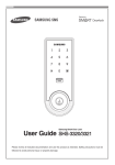
Chapter
3 Installation
Wiring
For safety and correct product connection, always install the product as shown in the wiring diagram below;
▶ 3 Interphones+ 2 Door phones (Door locks)
Interphone1
ISP
6
5
4
3
2
1
MS
Door Phone2
Door Phone1
Door Lock2
Door Lock1
Slave 1
2
2
3
3
Pin1~3 OFF
Interphone2
ISP
MS
SLAVE
6
5
4
3
2
1
6
5
4
3
2
1
Slave 2
6
5
4
3
2
1
JTAG1
1
1
2
1
2
3
2
3
3
Pin1-2 ON
Interphone3
ISP
LOCK2
LOCK1
BELL_1
J1
1
6
5
4
3
2
1
UART1
1
JTAG1
JTAG1
DOOR1
DOOR2
SLAVE
SLAVE3
SLAVE2
SLAVE1
6
5
4
3
2
1
MS
Slave 3
SLAVE
JTAG1
1
1
26
2
3
1
2
3
2
Master
3
Pin2-3 ON
27