1
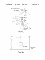
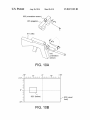
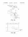
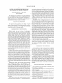
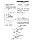
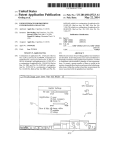
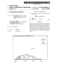
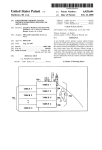
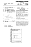
US008817103B2
(12) United States Patent
Scales et al.
(54)
(75)
SYSTEM AND METHOD FOR VIDEO IMAGE
REGISTRATION IN A HEADS UP DISPLAY
Inventors: John Richard Scales, Huntsville, AL
(US); Mark David Hose, Hunstville, AL
(Us)
(56)
Corporation, McLean, VA (US)
(*)
Subject to any disclaimer, the term of this
patent is extended or adjusted under 35
U.S.C. 154(b) by 998 days.
This patent is subject to a terminal dis
claimer.
(21) Appl. No.: 12/843,842
*Aug. 26, 2014
References Cited
U.S. PATENT DOCUMENTS
6,963,800
7,002,551
7,277,118
2006/0116814
B1
B2
B2
A1
11/2005
2/2006
10/2007
6/2006
Milbert
Azuma et a1.
Foote
Milbert
OTHER PUBLICATIONS
(73) Assignee: Science Applications International
Notice:
US 8,817,103 B2
(10) Patent N0.:
(45) Date of Patent:
QUANTUM3D, Inc., Daggers: Embedded Training for Dismounted
Soldiers Scients and Technology Objective (STO), http://www.
quantum3d.com/PDF/sstories/SStoriesiDaggers.pdf, 2004.
Sensor Technology Systems, Inc., Model 2733 Low Pro?le / Night
Vision Goggle: AN/PVS-2l: Operational Summary, 2004.
National Defense Magazine, Can the Army Make Objective Force
Warrior W0rk?, http://www.nationaldefensemagazine.org/articl.
cfm?Id:1173, Aug. 2003.
Intersense, Inc., Intersense InertiaCube2, http://www.isense.com/
products/prec/ic2/InertiaCube2.pdf, 2004.
Yeh, Michelle, et al., “Effects of Frame of Reference and Viewing
(22)
Filed:
Jul. 26, 2010
Condition on Attentional Issues with Helmet Mounted Displays”,
Technical Report, Jan. 1998, pp. 1-75.
(65)
Prior Publication Data
US 2010/0289724 A1
(Continued)
Nov. 18,2010
Primary Examiner * Young Lee
(74) Attorney, Agent, or Firm * Banner & Witcoff, Ltd.
(57)
Related U.S. Application Data
(62)
Division of application No. 11/000,934, ?led on Dec.
2, 2004, now Pat. No. 7,787,012.
(51)
Int. Cl.
H04N 7/18
U.S. Cl.
(52)
USPC
(58)
on the relative orientations of the camera and the display. As
the video camera moves with respect to the display, the
(2006.01)
........................................................ ..
348/158
Field of Classi?cation Search
CPC ................................................. .. G02B 27/0172
USPC
..
ABSTRACT
A system and method for aligning video images with an
underlying visual ?eld are provided. A video camera is
coupled with a heads up display, and a computer positions
images from the video camera on the heads up display based
.. 348/158, 218.1
IPC ....................................................... .. H04N 7/ 18
images are repositioned within the heads up display. The
video image, which may, for example, come from a weapon
sight, is aligned within the heads up display so that an
observer can easily view the camera image without having to
shift focus from the larger scene.
See application ?le for complete search history.
12 Claims, 10 Drawing Sheets
500 (infantryman)
506 (orientation sensor)
505 (goggles)
501
(computer)
US 8,817,103 B2
Page 2
(56)
References Cited
Primordial Soldier: Geographically-Enabled Augmented Reality
OTHER PUBLICATIONS
loaded from <http://www.primordial.com> on Dec. 1 l, 2006, date of
?rst publication not known, 35 pages.
“Primordial Soldier User manual”, downloaded from <http://www.
primordial.com> on Dec. 11, 2006, date of ?rst publication not
known, 26 pages.
System for Dismounted Soldiers (A05-ll9), Presentation, down
Livingston, MarkA., et a1 ., “Evaluating System Capabilities and User
Performance in the Battle?eld Augmented Reality System”, pub
lished in Proc. NIST/DARPA Workshop on Performance Metrics for
Intelligent Systems, Gaithersburg, MD, Aug. 24-26, 2004.
Hicks, Jeffrey, et al., “Eyekon: distributed Augmented Reality for
Solider Teams”, published in 21st Century Systems, Inc., 2001-2003,
pp. 1-14.
“Competitive Analysis: Ground Guidance”, downloaded from
<http://www.primordial.com> on Dec. 11, 2006, date of ?rst publi
cation not known, 9 pages.
“Whitepaper: Ground Guidance”, downloaded from <http://www.
primordial.com> on Dec. 11, 2006, date of ?rst publication not
known, 15 pages.
“Primordial Soldier: Vision System for Soldiers”, Product Sheet,
downloaded from <http://www.primordial.com> on Dec. 11, 2006,
date of ?rst publication not known, 2 pages.
“Primordial Soldier, Vision system software for soldiers”, down
loaded from <http://www.primordial.com> on Dec. 1 l, 2006, date of
?rst publication not known, 6 pages.
“Competitive Analysis: Unit Detection, Differentiating friend from
foe and assessing threats in a soldier’ s head-mounted display”, down
loaded from <http://www.primordial.com> on Dec. 1 l, 2006, date of
?rst publication not known, 8 pages.
“Whitepaper: Unit Detection, Differentiating friend from foe and
assessing threats in a soldier’s head-mounted display”, downloaded
from <http://www.primordial.com> on Dec. 11, 2006, date of ?rst
publication not known, 16 pages.
US. Patent
Aug. 26, 2014
101 (night
vision goggles
visual field)
Sheet 1 0f 10
102 (video feed
from weapon sight)
FIG. 1
(PRIOR ART)
US 8,817,103 B2
US. Patent
Aug. 26, 2014
Sheet 2 0f 10
US 8,817,103 B2
200 (night vision goggles visual fieid)
300
(video
camera
301 (cross
image)
hairs)
FIG. 2
400 (visual field)
401 (weapon
sight video feed)
FIG. 4
US. Patent
Aug. 26, 2014
Sheet 3 0f 10
US 8,817,103 B2
500 (infantryman)
506 (orientation sensor)
505 (goggles)
513 (cable)
'- 512 (cable)
'
503 (video gun sight)
504 (orientation sensor)
502 (rifle)
510 (cable)
501
(computer)
FIG. 5
US. Patent
Aug. 26, 2014
Sheet 4 0f 10
US 8,817,103 B2
SENSOR
606
visua! ?eld
‘
<
<
BEAM
COMBINER
605
COMPUTER
601
VIDEO SOURCE
602
|
|
l
|
|
i
i
I
I
l
SENSOR
:
603
|
|
§
ViDEO
z
i
US. Patent
Aug. 26, 2014
Sheet 5 0f 10
US 8,817,103 B2
I
i
l
I
I
,
I
I
I
COMPUTER
i
I
I
x
,
I
,
|
I
I
I
I
I
g
!
,
I
I
,
i
I <
x
,
I
,
I
g
!
,
l
I
I
,
710
k,\
HO
INTERFACE
vaO
INTERFACE
704
705
II
II
i NETWORK
glNTERFACE
5
706
iI
II
II
II
PROCESSOR
MEMORY
701
702
D$PLAY
INTERFACE
703
I
I
I
I
5
I
I
I
> '
I
I
I
I
I
I
I
I
I
I
I
I
i
I
I
x
,
I
,
|
I
I
I
I
I
I
I
I
US. Patent
Aug. 26, 2014
US 8,817,103 B2
Sheet 6 0f 10
START
801
/_/
—I
INITIATE
DISPLAY
I
802
F/
803
RECEIVE
ORIENTATION
DATA
RECEIVE
’
vIDEo FRAME
CALCULATE
PITCH & YAW
DELTA VALUES
I
808
Y
F)
CROP, RESIZE,
& ENHANCE
FRAME
I
809
/_/
DISPLAY FRAME
OVERLAYING
VISUAL FIELD
:05
DETERMINE
FRAME
LOCATION
I
A806
CALCULATE
ROLL
DELTA VALUE
I
810
ANOTHER
FRAME?
FIG. 8
DETERMINE
FRAME
ROTATION
:8
US. Patent
Aug. 26, 2014
Sheet 7 0f 10
US 8,817,103 B2
sensor)
FIG. 9A
-16°
+100
_8°
0°
I I I I | I I I | I | I I I I
+80
+16°
I I | I | I I I | I | I I I I
0° :
—:
-100
921 (frame)
-
j 920 (visual
_-
field)
'
FIG. QB
US. Patent
Aug. 26, 2014
US 8,817,103 B2
Sheet 8 0f 10
905 (orientation sensor)
901 (goggles)
(orientation
sensor)
FIG. 10A
-16°
+100
_8°
0°
l I l I | I l I | I l I l I |
+80
+16°
l I l I l I l I | I l I l I l
0° :
_:
1021 (frame)
_
40°
I920 (visual
field)
'
FIG. 1OB
US. Patent
Aug. 26, 2014
Sheet 9 0f 10
US 8,817,103 B2
905 (orientation sensor)
0
Y
901 (goggles)
K
i
Z
(orientation
sensor)
FIG. 11A
-16°
+10°
O
o
0°
_8°
|||||||||||||||
+80
+16°
IIIIIIIIIIIIIII
1 121 (frame)
I 920 (visual
field)
FIG. 11B
US. Patent
Aug. 26, 2014
Sheet 10 or 10
US 8,817,103 B2
905 (orientation sensor)
901 (goggles)
Y
X
Z
911 (rifle)
(orientation
sensor)
+100
-16°
_8Q
0°
+80
+16°
llllllllllllllllllllllllllllll
0° _:-
1221 (frame)
I 920 (visuai
-10°
_
FIG. 128
US 8,817,103 B2
1
2
SYSTEM AND METHOD FOR VIDEO IMAGE
REGISTRATION IN A HEADS UP DISPLAY
envisioned a technological revolution for the foot soldiers of
tomorrow, dubbed Future Force Warrior. The project envi
CROSS-REFERENCE TO RELATED
APPLICATIONS
sions, among other improvements, the porting of an infantry
man’s weapon sight into a heads up display (HUD) built into
his night vision goggles. Such goggles exist now, as in Sensor
Technology Systems’ Model 2733 Low Pro?le Night Vision
This application is a divisional of US. patent application
Ser. No. 11/000,934, titled “System and Method for Video
Image Registration in a Heads Up Display” and ?led Dec. 2,
2004, now US. Pat. No. 7,787,012, which application is
Goggle. They have the ability to port a video feed into a beam
combiner, overlaying a video image from a video source
mounted in the weapon sight onto the center of the visual ?eld
incorporated by reference herein in its entirety.
An example of such a combined image appears as prior art
FIG. 1. Here, the video feed 102 from a weapon’s sight is
superimposed directly into the center of the night vision go g
gle’s visual ?eld 101. This is accomplished using a beam
combiner, which optically overlays one image over another.
Both images depict the same subjects, a group of soldiers
ofthe goggles.
FIELD OF THE INVENTION
The invention relates generally to the display of video
images. More particularly, the invention provides a method
and system for registering a video image with an underlying
accompanying an armored personnel carrier (APC). How
visual ?eld, such as in a heads up display.
BACKGROUND OF THE INVENTION
ever, the video feed 102 remains stationary in the center of the
visual ?eld 101, obscuring content in the center of the visual
20
?eld, in this case the APC and a soldier. The two images are
distinctly offset, with the two soldiers to the right of the APC
Modern warfare has seen its share of technological
improvements which have led to weapons that can be targeted
being repeated in both images. This offset, with two distinct
images of the same target appearing in different places in the
?eld of view, could confuse the soldier, causing a delay in
with ever increasing levels of speed and accuracy, enabling
weapon operators to react more quickly when a situation
25
suddenly changes. While tanks, jets, missiles, combat plan
ning systems, and other technological implements have kept
engagement or a miss. If the soldier moves his weapon and
turns his head simultaneously, the set of images moving in
different directions may be even more confusing and disori
pace with modern electronics, some familiar tools of modern
enting to the soldier, potentially decreasing the soldier’s abil
warfare have remained virtually unchanged for centuries.
Perhaps foremost among these essential components is the
infantryman: the soldier carrying light arms deployed on foot.
ity to react and the accuracy of any shot ?red.
Thus, it would be an advancement in the art if a video
image from a video source could be integrated into the visual
30
Infantrymen have bene?ted to some extent from modern
?eld of a heads up display without con?lsing or disorienting
technology with the advent of laser sights, night vision
the observer, and without needlessly obscuring relevant
goggles, and so forth. These have allowed the foot soldier to
navigate at night, and accurately dispatch their targets. These
technologies ultimately help to keep the soldier safe under the
cover of darkness, help give the element of surprise when
visual content.
35
SUMMARY OF THE INVENTION
needed, and also help ensure that the ?rst shot ?red is the one
that hits the mark.
In spite of these advances, one problem which persists is
the cumbersome process of acquiring and striking a target. At
A ?rst embodiment of the invention provides a method for
aligning video images with an underlying visual ?eld by
40
ing a display orientation of a transparent display overlaying
the visual ?eld, and displaying video images in the transpar
night, modern night vision goggles passively amplify minis
cule amounts of ambient light, such as starlight, and enable a
soldier to see obscured targets in the dark. Once a target is
found in this fashion, however, a soldier must ?ip the goggles
out of the way and reacquire the target with the sight on his
weapon. This takes time away from the soldier, during which
he might be seen by the target itself, or the target might move.
In addition, reacquisition with the weapon’ s narrower ?eld of
vision may be virtually impossible with a distant or moving
determining a source orientation of a video source, determin
45
ent display, wherein a position for the images is based on the
source orientation and the display orientation.
A second embodiment of the invention provides a system
for displaying a portion of a video feed overlaying a visual
?eld comprising a video camera, a heads up display (HUD),
and a computer. Orientation sensors are af?xed to the video
camera and the HUD. The computer is adapted to receive
50
target.
sensor data from both orientation sensors, to receive the video
feed from the video camera, and to display video images in
the HUD.
Alternatively, a soldier, upon viewing a target with night
vision goggles, may engage a laser illuminator on his
weapon. The illuminator projects a beam of laser light fol
lowing the line of sight of the weapon and striking where the
BRIEF DESCRIPTION OF THE DRAWINGS
55
FIG. 1 illustrates a prior art example of a stationary video
feed overlaying a visual ?eld.
FIG. 2 illustrates an example of a visual ?eld produced by
bullet will strike. The soldier can keep his goggles on and see
the illuminated point. He can move the point of the illumina
tor until it points to his target, and then ?re as needed. While
somewhat faster than lifting the goggles and reacquiring the
target through the weapon sight, the illuminator may have the
unintended effect of giving away the soldier’s position. The
night vision goggles.
60
FIG. 4 illustrates the image produced by an illustrative
laser illuminator may be just as obvious to an enemy as it is to
the soldier. In the time it takes to maneuver his weapon into
position, he may already be spotted and in the weapon sight of
his enemy.
In the hopes of solving this and other problems inherent
with current infantry technology, US. military planners have
FIG. 3 illustrates an example image from a video camera
capturing the same scene as the visual ?eld of FIG. 2.
65
embodiment of the invention.
FIG. 5 illustrates the system employed by an illustrative
embodiment of the invention.
FIG. 6 is a block diagram which depicts the functional
components of an illustrative embodiment of the invention.
US 8,817,103 B2
3
4
FIG. 7 is a block diagram which depicts the functional
components of a computer employed by an illustrative
embodiment of the invention.
FIG. 8 illustrates a method for registering a video image
with an underlying visual ?eld.
FIG. 9A depicts an illustrative embodiment of the inven
tion with a video source and heads up display visually
discard unneeded visual information, cropping the image to
perhaps one quarter of its original size. In addition, the video
feed 401 has been positioned over the portion of the visual
?eld 400 based on the direction the video source is pointed.
As the weapon moves, the video feed 401 is dynamically
positioned within the visual ?eld 400. Ultimately, by super
imposing the two images, a soldier with a heads up display
aligned.
and a weapon mounted video camera is able to simulta
FIG. 9B illustrates a combined image created by the illus
trative embodiment of FIG. 9A.
FIG. 10A depicts an illustrative embodiment of the inven
tion with a video source and heads up display visually offset
neously survey a setting, acquire a target, and point his
weapon at the target without taking time to shift from goggles
to weapon sight.
It should be noted upfront that this superimposition of
horizontally.
video images is not limited to weapon usage on a battle?eld,
although that is the dominant example used here. Other
FIG. 10B illustrates a combined image created by the illus
trative embodiment of FIG. 10A.
FIG. 11A depicts an illustrative embodiment of the inven
tion with a video source and heads up display visually offset
myriad of settings, including law enforcement, medicine, etc.
vertically.
provide a magni?ed view of an operating ?eld embedded
within a view of the entire patient’ s chest cavity. An astrono
FIG. 11B illustrates a combined image created by the illus
trative embodiment of FIG. 11A.
FIG. 12A depicts an illustrative embodiment of the inven
tion with a video source and heads up display visually offset
in rotation.
FIG. 12B illustrates a combined image created by the illus
trative embodiment of FIG. 12A.
embodiments of the current invention could be used in a
For example, a surgeon could use such a device on his hand to
20
mer could survey a star ?eld visually while wearing some
form of heads up display. Her telescope could be ?tted with a
video camera, the feed from which is dynamically fed into
and positioned within the HUD. As such, she can view a
25
magni?ed video image from the telescope without having to
reposition herself before the telescope’s eyepiece. Altema
tively, her video source could produce a modi?ed output,
perhaps displaying a color-shifted spectrographic view of the
DETAILED DESCRIPTION OF THE INVENTION
light from a particular star. Similarly, a nephologist can sur
vey a sky full of clouds and simultaneously focus in on clouds
FIG. 2 illustrates an example of a visual ?eld 200 as seen
through the night vision goggles a foot soldier might wear.
30
of particular interest without shifting. An ichthyolo gi st, ?tted
The image enhances ambient light, typically starlight, to
with an underwater embodiment of the invention, could sur
enable the soldier to see into the night. The visual ?eld depicts
a handful of potential targets for the foot soldier. FIG. 3
vey a school of ?sh and simultaneously focus in on a particu
lar ?sh. In each of these alternative embodiments, a secondary
illustrates an example image 300 from a video camera cap
turing the same scene as the visual feed of FIG. 2. The video
camera producing the image 300 may be attached to a weapon
video source is used to dynamically supplement an observer’ s
35
carried by the foot soldier. The image 300 may be the product
of a specialized camera or weapon sight, such as a thermal
imager which makes infrared wavelengths visible, a starlight
scope which ampli?es ambient light using the same technol
40
?eld of view.
FIG. 5 illustrates a system employed by an illustrative
embodiment of the invention. Here, an infantryman 500 is
?tted with goggles 505, a ri?e 502 with video gun sight 503,
and ?eld computer 501. The goggles 505 may produce a
visual ?eld similar to the one illustrated in FIG. 2. The video
gun sight 503 produces a video feed, possibly including cross
hairs as in FIG. 3, depicting the line of sight of the ri?e 502.
ogy which enables night vision goggles, or any other video
source such as a standard television camera. The video feed
includes cross hairs 301 so that a soldier viewing the video
The video weapon sight 503 may produce more than a stan
feed will know exactly where a shot ?red will hit. In addition,
the video camera may magnify the image to aid target recog
dard unmagni?ed view, for example a magni?ed view, a
thermal view, a night vision view, an image intensi?er view,
45
nition and to increase accuracy.
or some combination thereof.
The visual ?eld 200 and the video image 300 differ in their
?eld of view (FOV). The visual ?eld of the night vision
goggles allows for a greater amount of visual information to
In this embodiment, ?eld computer 501 receives a video
feed from video weapon sight 503 via cable 512. The video
feed may be delivered using any standard video format, for
example analog formats like NTSC or PAL, or digital formats
like MPEG, or any non-standard format. The ?eld computer
be viewed by the observer simultaneously without the
50
observer having to move his head. The FOV of the video
image 300, as from a weapon sight, is normally much nar
rower, presenting less of the visual ?eld to the observer. As a
result, a soldier looking directly through a weapon sight, or
looking at the video feed produced by such a sight, will have
501 receives sensor data from orientation sensors 504 and
55
to move the weapon in order to view the entire scene. For this
reason, soldiers may search for and acquire targets at night
using the wider FOV of night vision goggles, and switch to
the weapon sight view only once they have decided upon a
target. This takes time, thus slowing down the soldier.
The visual ?eld 400 of FIG. 4 illustrates the image pro
duced by an illustrative embodiment of the invention. The
visual ?eld 400, here the view through a soldier’s night vision
goggles or other (clear) goggles, is enhanced with the addi
tion of a portion of the weapon sight video feed 401 through
the use of a heads up display (HUD). With this embodiment of
the invention, the video feed 401 may be modi?ed so as to
60
65
506, via cables 510 and 511. Once the video feed is processed,
?eld computer 501 delivers video for the heads up display
within the goggles 505, via cable 513.
The sensor 504 a?ixed to ri?e 502 sends data relaying the
orientation of the weapon and attached video gun sight 503.
This data may include angular pitch, yaw, and roll informa
tion, sent in frequent intervals. An example of such a sensor is
InterSense’s IntertiaCube3®, which uses the earth’s gravita
tional and magnetic ?elds (among other means) to sense and
report angular orientation around three axes of rotation up to
180 times per second. The sensor 506 a?ixed to goggles 505
relays similar orientation data, except that it reports on the
line of sight of the goggles instead of the ri?e 502. It should be
noted that sensors 504 need not be directly a?ixed to the ri?e
502, so long as it moves with the ri?e. For example, it could
US 8,817,103 B2
5
6
be attached to the gun sight 503. Likewise, sensor 506 need
not be directly a?ixed to the goggles 505. The sensor 506
could also be attached to the helmet of the infantryman 500.
In this embodiment, sensors 504, 506 use Universal Serial
not be perfectly transparent, but also might be translucent
allowing only some light to pass through. The video output of
computer 601 is placed in front of the visual ?eld 610, creat
ing what is sometimes referred to as a heads up display or
HUD. Such displays allow an observer to receive information
Bus (USB) cables 510, 511 to relay angular data, although
any communication method is feasible. These cables, along
or images while simultaneously viewing a visual ?eld, pre
venting the observer from having to look away.
FIG. 7 is a block diagram depicting the functional compo
with video cables 512, 513 may either be exposed or sewn
into a soldier’s clothing or his ri?e sling to prevent entangle
ment of the wearer. Although wired sensors and video cables
are used here, any form of wireless radio is feasible. For
nents of a computer employed by an illustrative embodiment
of the invention. The functional components of computer 601
illustrated here are merely representative of functions. Indi
vidual functions may be combined or divided among multiple
components within the device. Here, processor 701 is con
nected to memory 702 via bus 710. Memory 702 may include
example, Ultra-wideband (UWB) transceivers may transmit
video and sensor data from the weapon, and sensor data from
the goggles. Likewise, UWB may be used to transmit video
from the ?eld computer 501 to the goggles 505. Although
UWB radios, such as Time Domain’s PulsON® radio, are
volatile memory, such as random access memory (RAM), or
non-volatile memory, such as Flash or a hard disk drive. Also
particularly desirable for their high bandwidth, low power
consumption and for being virtually undetectable, any wire
less standard may be used, including both Bluetooth and
connected to processor 701 is Input/Output Interface 704,
which may communicate with and pass data from connected
IEEE 802.11.
In alternative embodiments, UWB radios may be used for
20
more than transmission of video and sensor data. Multiple
radios may be placed on the ri?e 502 and on the goggles 505
(or on the helmet, to which the goggles may be a?ixed), each
of which can relay their precise position. In this fashion, the
?eld computer 501 may be able to calculate the alignment of
USB or a wireless standard, such as UWB or Bluetooth. Video
interface 705 receives video signals and relays them for stor
age in memory 702 or processing in processor 701. Display
interface 703 relays video signals to an external display, such
25
as the HUD. Optional network interface 706 may be used to
communicate with an external computer, possibly to transmit
and receive position and situational data (to other team mem
bers, or via satellite back to headquarters). Bus 710 may be
30
cating between components.
the ri?e and goggles based on the relative location of radios
rather than use separate orientation sensors.
In other alternative embodiments, the heads up display
need not be connected to the viewer, as through a pair of night
vision goggles. For example, the heads up display could
peripherals, including orientation sensors, perhaps using
comprised of a single or multiple signal buses for communi
appear before a windshield in a vehicle. A weapon mounted
FIG. 8 demonstrates an illustrative embodiment of a
on the vehicle includes a video gun sight producing images
processed and projected onto the heads up display. In this
method for registering a video image with an underlying
visual ?eld. It should be noted that the steps pictured here may
be reordered, combined, or split to achieve a similar result.
embodiment, an orientation sensor may be placed to sense the
orientation of the vehicle rather than a pair of go ggles worn by
the observer. This embodiment may be particularly useful for
remotely controlled weapon systems, for example a robot
35
Step 801 initiates the method when the heads up display is
initiated, either through a switch attached to a video source or
gun sight, a switch on a computer, or perhaps on the heads up
carrying a weapon. The current state of the art uses two
display itself. Alternatively, the display may be initiated when
screens, one for navigation and one for aiming the weapon. A
robot operator uses one screen to drive the robot and acquire
targets, then refers to an adjacent screen to aim and ?re the
a weapon is removed from its safety setting. Once initiated, at
step 802, a video frame is received for processing. The frame
may be processed digitally, and if it is received in analog form
40
weapon. Registering the weapon video image to the naviga
may ?rst need to be converted to a digital format for process
mg.
tion screen in a manner similar to an infantryman gamers
similar advantages for the robot operator. Additionally,
because a robot’s weapon is typically turret-mounted, sensors
may be replaced with similar gear or other positional readouts
based on turret position, laser range?nderposition, or weapon
Along with the receipt of a video frame, orientation data
45
in the form of pitch, yaw, and roll angular values or in quar
temions. Such values indicate the angle of vertical rise
elevation position.
FIG. 6 is a block diagram which depicts the functional
components of an illustrative embodiment of the invention.
Here, computer 601 receives sensor data and a video feed
50
from video assembly 604, along with sensor data from heads
up display assembly 607. Video assembly 604 is composed of
video source 602 and sensor 603 af?xed to detect the orien
tation of the video source. Video source 602 has a visual ?eld
55
the difference in yaw values. By knowing the pitch delta and
yaw delta, the location of the processed frame within a heads
up display is determined, as in step 805. In determining the
location, the pitch delta and yaw delta values are mapped
signal delivered to computer 601. Heads up display assembly
bined with the processed video signal delivered from com
puter 601. This combination of video signal with visual ?eld
may be created through the use of a transparent display, such
as a piece of glass set at an angle. The glass may pass light
from the visual ?eld 610 to the observer while simultaneously
(pitch), the angle of horizontal rotation (yaw), and the angle
of rotation around the line of sight (roll), for both the display
and the video source. Having this data, in step 804, the dif
ference in pitch and yaw values between the display and the
video source can be calculated. The pitch delta is the differ
ence in pitch values from the two sensors, and the yaw delta is
611 from which it receives light and converts it to the video
607 is composed of beam combiner 605 and sensor 606
a?ixed to detect the orientation of the beam combiner. Beam
combiner 605 has a visual ?eld 610, whose image is com
may be received from sensors attached to a heads up display
and a video source, as in step 803. This data may be received
from degrees to pixels. This calculation requires determining
60
the number of pixels in a degree of vision, and then multiply
ing that number by the pitch delta and yaw delta values to
determine vertical and horizontal offset from the center of the
65
visual ?eld in pixels.
In step 806, the roll delta value is determined in similar
fashion, by ?nding the difference between the roll values
re?ecting light from a video display strategically placed
sensed at the video source and display. Based on the roll delta,
based on the angle of the glass. The transparent display need
the processed frame can be rotated for presentation within the
US 8,817,103 B2
7
8
heads up display, as in step 807. Various algorithms for rotat
ing an image by a certain number of degrees are well known
the heads up display goggles 901. The example visual ?eld
in the art.
horizontally (yaw) and 20 degrees vertically (pitch). If the
Once the location and rotation of the processed frame
within the display are determined, the frame may be cropped,
discarding unneeded pixels, as in step 808. The frame may be
resized in order to map the video information onto the pixels
that will ultimately be used in a heads up display. This step
may be necessary if the video images produced by a video
pitch delta and yaw delta values are zero (i.e., the goggles and
video source are aligned), then the frame 921 is displayed in
the center of the visual ?eld 920, as shown here. The roll delta
value is also zero here, because the ri?e 911 and goggles 901
are both rotationally aligned with each other aron their
source are larger than needed for display. For example, if a
out rotation.
video image initially has a ?eld of view of 8 degrees horizon
tal and 6 degrees vertical, it may be cropped down to 4 degrees
horizontal and 3 degrees vertical, retaining the same center
point. In this fashion, only a quarter of the image is retained,
but it constitutes the most relevant part of the image. Alter
however, the ri?e 911 has been rotated horizontally by 8
degrees to the left. FIG. 10B depicts the subsequent change in
the visual ?eld 920. The pitch and roll values detected by
920 for the goggles 901 has a ?eld of view that is 32 degrees
respective Z-axes. As such, the frame 921 is displayed with
FIG. 10A depicts the same components as FIG. 9A. Here,
natively, the video frame may need to be magni?ed or com
pressed in order to adjust for differences in magni?cation
between the visual ?eld and the native video frame. In addi
tion, the frame may be enhanced by adding a border around
the frame so as to further distinguish it from the visual ?eld
20
heads up display, shifting it to the left as shown. If the yaw
value exceeds the visual ?eld width, the frame may still
appear within the visual ?eld, but with a distinctive border,
indicating to the user that the ri?e is pointing outside the
for an observer.
The processed video frame, at this point, may be displayed
in a heads up display, as in step 809. The colored pixels of the
processed frame are surrounded by dark or black pixels,
which equate to transparent in a heads up display. The dis
played frame appears before a visual ?eld from the perspec
tive of an observer of the visual ?eld. The calculated position
and rotational orientation of the processed frame place it on
the display approximately in front of the same subject matter
depicted in the visual ?eld. In addition to the frame itself,
additional information may be added to the display, for
orientation sensor 915 remain unchanged. However, the yaw
value detected will change by 8 degrees to the left. When this
is compared to the values detected by the orientation sensor
905 a?ixed to goggles 901, which haven’t changed, the yaw
delta value will be —8 degrees. When processed, this yaw
delta value will change the placement of the frame 1021 in the
25
visual ?eld. The frame remains visible, however, giving the
user a view of where the weapon is pointing. The frame
position will be in the direction of the actual weapon pointing
direction, allowing the user to rapidly and instinctively adjust
30
his visual ?eld or his weapon to bring the two back together.
FIG. 11A again depicts the same components as FIG. 9A.
Here, the ri?e 911 has been rotated vertically (rather than
example, battery life data. The ?nal display image, including
horizontally) up 6 degrees. FIG. 11B depicts the subsequent
the processed and repositioned video frame and any other
information, is sent to the display, possibly using a standard
change in the visual ?eld 920. The yaw and roll values
detected by orientation sensor 915 remain unchanged, but the
pitch value detected will change, up 6 degrees. When com
pared to the unchanged values from the orientation sensor 905
video format such as 12-bit Video or NTSC.
35
At this point in the process, at decision 810, if another
frame of video is set to be received (i.e., the display is still on),
then the process repeats for each new frame, returning to step
802. In this fashion, each frame of video is individually pro
ces sed, modifying the frame, positioning and rotating it based
a?ixed to the goggles 901, the pitch value will be +6 degrees.
When frame 1121 is processed, this pitch delta value will
change the placement of the frame in the heads up display,
40
on the difference in orientations between the video source and
the display, and then displaying it. As such, if the video source
moves from left to right, then its orientation data will change,
and subsequent displayed frames will move left to right
across the visual ?eld, aligning or registering each frame with
the portion of the visual ?eld it overlays. Once there are no
shifting it up as shown.
FIG. 12A is a ?nal depiction of the same components as
FIG. 9A. Here, the ri?e 911 has been rolled aron its line of
sight by 10 degrees, counterclockwise. FIG. 12B depicts the
subsequent change in the visual ?eld 920. The pitch and yaw
longer any frames to be processed (i.e., the display has been
values detected by the ri?e’s orientation sensor 915 remain
unchanged, but the roll value detected is different, counter
clockwise 10 degrees. When compared to the unchanged
turned off), the process comes to an end.
values from the orientation sensor 905 af?xed to the goggles
45
FIG. 9A depicts an illustrative embodiment of the inven
tion in the form of a video source 912 a?ixed to ri?e 911 and
50
heads up display goggles 901. The direction that ri?e 911 and
video source 912 are pointing is sensed by orientation sensor
915. The line of sight for the video source is indicated by the
Z-axis on axes 916. The direction that heads up display
goggles 901 are pointing is sensed by orientation sensor 905.
The line of sight for the goggles 901 is indicated by the Z-axis
55
901, the roll delta value will be 10 degrees. When frame 1221
is processed, this roll delta value will change the rotation of
the frame in the heads up display, rotating it counterclock
wise. It should be noted that although FIGS. 10A-12B depict
only motion around a single axis at a time, the technique may
be applied to motion in all directions.
One possible consideration for the above described meth
ods and systems is the problem of parallax. That is, because a
on axes 906. Here, axes 906 and 916 are in alignment. The
video source and a heads up display are separated by some
goggles are looking in exactly the same direction as the
weapon is pointed. As such, the orientation sensors 905 and
915 will output the same values for pitch, yaw and roll.
distance (e.g. 0.5 meters), if both devices are perfectly
aligned, they will in fact be looking at slightly different
60
The effect of this upon the heads up display is depicted in
FIG. 9B, which illustrates a combined image created by the
illustrative embodiment of FIG. 9A. When a frame 921 from
the video source 912 is processed using an embodiment of the
invention, it is placed in the center of the visual ?eld 920, as
shown. Here, the visual ?eld is depicted with increments of
degrees which represent the ?eld of view, in this case through
65
points. As a result, in processing a video frame, the location
where the frame is placed may be slightly off, and a displayed
frame of video will not be aligned as perfectly as possible.
However, this problem diminishes as the distance to a target
increases. The further away the target, the smaller the change
in degrees, and hence the smaller the error produced. For
example, a target at 10 meters with 0.5 meters between gun
sight and goggles produces an error of about 2.9 degrees in the
US 8,817,103 B2
9
10
placement of the video frame. At 100 meters, with the same
0.5 meters between gun sight and goggles, the error is only
ciate that there are numerous variations and permutations of
the above described systems and techniques. Thus, the spirit
0.29 degrees in the placement of the video frame.
and scope of the invention should be construed broadly as set
forth in the appended claims.
The problem of parallax is to some extent a non-issue. The
system proposed would likely be used for targets at distances
We claim:
greater than 10 meters more often than not. Moreover, when
1. A system comprising:
targeting a weapon using the system, the video frame dis
played in the heads up display will ultimately be the source of
a video camera adapted to provide, in a video feed, data for
a series of video images representing portions of a visual
assurance that a soldier’s weapon is pointed at a proper target.
?eld;
Even if a video gun sight image is slightly misaligned with the
visual ?eld surrounding it, the soldier will primarily care that
his weapon is pointed at the correct target. Further, the abso
a ?rst orientation sensor adapted to detect an orientation of
the video camera;
a heads up display (HUD) adapted for viewing of the visual
lute amount of misalignment will be only 0.5 meters at worst
?eldby a user of the system wherein the HUD comprises
a transparent display, and wherein the HUD and the
video camera are independently movable about multiple
using the above example. The video gun sight image will still
appear over or next to the intended target. Note that weapon
accuracy is governed by zeroing the weapon and the video
gun sight image, so parallax has no effect on bullet accuracy.
To the extent that parallax is an issue, it can be handled in
several ways. One solution is to integrate a range ?nder, such
as a laser range ?nder, into the system to automatically detect
axes;
a second orientation sensor adapted to detect an orientation
of the HUD; and
20
the distance of targets and, given a known weapon-goggle
from the video camera, and to display the video images,
distance, adjust the image placement accordingly. Another
on the transparant display and based on the received
solution is to provide a range adjustment control which a
soldier can use to manually adjust the range to a target, and
accordingly adjust image placement.
Parallax may also be an issue when calibrating the orien
tation sensors. Calibration may be required when initially
con?guring the invention, and may also be required if a severe
jolt to the system causes misalignment of the sensors. One
solution may be to provide a button which is pushed to signal
calibration. While holding the button, a reticle may appear in
the center of the visual ?eld while the video image may
appear motionless off to the side. Once the visual ?eld and
sensor data, in positions that overlay portions of the
25
30
2. The system of claim 1, wherein the HUD is housed in a
parallax will induce an angular error in closer targets, as
described above.
40
4. The system of claim 1, wherein
the ?rst orientation sensor is af?xed to the weapon and,
While the invention has been described with respect to
carrying out the invention, those skilled in the art will appre
images.
pair of night-vision goggles.
6. The system of claim 5, wherein the video camera is
45
attached to a weapon.
7. The system of claim 6, wherein the video camera is a
thermal gun sight.
8. The system of claim 1, wherein the video camera is a
such, well known rigid or non-rigid image registration tech
niques may be used to register the images by, for example,
speci?c examples including presently preferred modes of
the computer is adapted to resize and crop the video
5. The system of claim 1, wherein the HUD is housed in a
image, along with the video images from the video source, are
both fed into a computer for initial digital processing. As
the resultant combination of video image and goggle image.
3. The system of claim 1, wherein the video camera is
attached to a weapon and the video feed is of a line of sight of
the weapon.
the video camera is a weapon sight attached to a weapon,
Alternative embodiments may provide additional solutions
to the issue of parallax. In one such embodiment, the image
produced in the visual ?eld of a display is captured by a
up display alone, or the heads up display may be ?lled with
determine a source orientation of the video camera, and
determine a display orientation of the transparent display.
pair of goggles.
35
starting point from which to search the goggle image. Once
the precise location of the video image is registered within the
goggle image, the video image can be more accurately
aligned. The video image may then be displayed in the heads
wherein boundaries of the displayed video images are in
registration with boundaries of portions of the visual
?eld represented by the displayed video images, and
video image are both centered on the same target, releasing
?nding common visual elements between them. This process
is accelerated by having, based on the orientation data, a
visual ?eld represented by the displayed video images
wherein the computer is adapted to
the calibration button signals alignment to the system. The
portion of the invention which calculates the position of the
video image may then adjust its calculations accordingly.
Centering on a distant target (for example, greater than 300
meters) during the calibration routine may be required as
second video camera. This second video feed or goggle
a computer adapted to receive sensor data from the ?rst and
second orientation sensors, to receive the video feed
50
thermal gun sight.
9. The system of claim 1, wherein the computer is adapted
to reposition the displayed video images within the transpar
ent display when the video camera or transparent display
moves.
10. The system of claim 9, wherein the video camera is
attached to a weapon.
55
11. The system of claim 10, wherein the video feed is of a
line of sight of the weapon.
12. The system of claim 1, wherein the computer is a ?eld
computer adapted to be worn and carried by a human user.
*
*
*
*
*