1
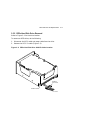
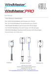
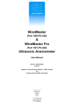
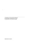
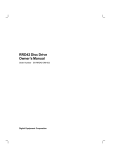
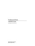
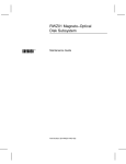
dt
BA46 Storage Expansion Box Service
Information
EK-VBA46-SV.001
Digital Equipment Corporation
Maynard, Massachusetts
First Edition, February 1992
The information in this document is subject to change without notice and should not
be construed as a commitment by Digital Equipment Corporation. Digital Equipment
Corporation assumes no responsibility for any errors that may appear in this document.
The software described in this document is furnished under a license and may be used or
copied only in accordance with the terms of such license.
No responsibility is assumed for the use or reliability of software on equipment that is not
supplied by Digital Equipment Corporation or its affiliated companies.
Restricted Rights: Use, duplication, or disclosure by the U. S. Government is subject to
restrictions as set forth in subparagraph ( c ) ( 1 ) ( ii ) of the Rights in Technical Data
and Computer Software clause at DFARS 252.227–7013.
Copyright © by Digital Equipment Corporation 1992
All Rights Reserved.
Printed in U.S.A.
The following are trademarks of Digital Equipment Corporation: DEC, Digital, VAX, VMS,
and the DIGITAL logo.
This document was prepared using VAX DOCUMENT, Version 2.0.
Contents
Preface
1
vii
BA46 Storage Expansion Box
1.1
Overview . . . . . . . . . . . . . . . . . . . . . . . . . . . . . . . . . . . . . . . .
1.1.1
Specifications . . . . . . . . . . . . . . . . . . . . . . . . . . . . . . . . . . .
1.2
SCSI ID Settings . . . . . . . . . . . . . . . . . . . . . . . . . . . . . . . . . .
2
Mass Storage Devices
2.1
2.1.1
2.2
2.2.1
2.3
2.3.1
2.4
2.4.1
2.5
2.5.1
3
1–1
1–4
1–5
RZ5x Hard Disk Drives . . . . . . . . . . . . . . . . . . . . . . . . . . . . . 2–2
SCSI ID Settings for RZ5x Hard Disk Drives . . . . . . . . . . 2–2
TLZ04 Cassette Tape Drive . . . . . . . . . . . . . . . . . . . . . . . . . . 2–4
SCSI ID Settings for the TLZ04 Tape Drive . . . . . . . . . . . . 2–4
TZ30 Cartridge Tape Drive . . . . . . . . . . . . . . . . . . . . . . . . . . 2–6
SCSI ID Settings for the TZ30 Cartridge Tape Drive . . . . . 2–6
TZK10 (QIC) Cartridge Tape Drive . . . . . . . . . . . . . . . . . . . . 2–8
SCSI ID Settings for the TZK10 Tape Drive . . . . . . . . . . . 2–8
RRD42 CDROM Disc Drive . . . . . . . . . . . . . . . . . . . . . . . . . . 2–10
SCSI ID Settings for the RRD42 CDROM Drive . . . . . . . . 2–10
FRU Removal and Replacement
3.1
3.2
3.3
3.4
3.4.1
3.4.2
3.5
3.5.1
3.5.2
3.5.3
Precautions . . . . . . . . . . . . . . . . . . . . . . . . . . . .
BA46 Expansion Box Part Numbers . . . . . . . . .
System Preparation . . . . . . . . . . . . . . . . . . . . . .
Front Bezel . . . . . . . . . . . . . . . . . . . . . . . . . . . .
Bezel Removal . . . . . . . . . . . . . . . . . . . . . . . .
Bezel Replacement . . . . . . . . . . . . . . . . . . . . .
Mass Storage Device Removal and Replacement
Getting Started . . . . . . . . . . . . . . . . . . . . . . .
RZ5x Hard Disk Drive Removal . . . . . . . . . . .
RZ5x Hard Disk Drive Replacement . . . . . . .
.
.
.
.
.
.
.
.
.
.
.
.
.
.
.
.
.
.
.
.
.
.
.
.
.
.
.
.
.
.
.
.
.
.
.
.
.
.
.
.
.
.
.
.
.
.
.
.
.
.
.
.
.
.
.
.
.
.
.
.
.
.
.
.
.
.
.
.
.
.
.
.
.
.
.
.
.
.
.
.
.
.
.
.
.
.
.
.
.
.
. 3–2
. 3–2
. 3–6
. 3–7
. 3–7
. 3–7
. 3–8
. 3–8
. 3–9
. 3–10
iii
iv Contents
3.5.4
RRD42 CDROM Drive Removal . . . . . . . . . . . . . . . . .
3.5.5
RRD42 CDROM Drive Replacement . . . . . . . . . . . . .
3.5.6
TZ30 Cartridge Tape Drive Removal . . . . . . . . . . . . .
3.5.7
TZ30 Cartridge Tape Drive Replacement . . . . . . . . . .
3.5.8
TLZ04 Cassette Tape Drive Removal . . . . . . . . . . . . .
3.5.9
TLZ04 Cassette Tape Drive Replacement . . . . . . . . . .
3.5.10 TZK10 (QIC) Cartridge Tape Drive Removal . . . . . . .
3.5.11 TZK10 (QIC) Cartridge Tape Drive Replacement . . . .
3.6
Power Supply . . . . . . . . . . . . . . . . . . . . . . . . . . . . . . . . .
3.6.1
Power Supply Removal . . . . . . . . . . . . . . . . . . . . . . .
3.6.2
Power Supply Replacement . . . . . . . . . . . . . . . . . . . .
3.7
Load Module . . . . . . . . . . . . . . . . . . . . . . . . . . . . . . . . .
3.7.1
Load Module Removal . . . . . . . . . . . . . . . . . . . . . . . .
3.7.2
Load Module Replacement . . . . . . . . . . . . . . . . . . . . .
3.8
Restoring the Expansion Box . . . . . . . . . . . . . . . . . . . . .
3.9
Testing the System and Expansion Box After Adding a
Device . . . . . . . . . . . . . . . . . . . . . . . . . . . . . . . . . . . . . .
4
.
.
.
.
.
.
.
.
.
.
.
.
.
.
.
.
.
.
.
.
.
.
.
.
.
.
.
.
.
.
.
.
.
.
.
.
.
.
.
.
.
.
.
.
.
.
.
.
.
.
.
.
.
.
.
.
.
.
.
.
3–12
3–13
3–13
3–14
3–15
3–16
3–17
3–17
3–18
3–18
3–18
3–19
3–19
3–19
3–20
. . . . 3–21
Preventive Maintenance and Problem Solving
4.1
TLZ04 Cassette Tape Drive Preventive Maintenance .
4.2
Problem Solving . . . . . . . . . . . . . . . . . . . . . . . . . . . . .
4.2.1
RZ5x Hard Disk Drives . . . . . . . . . . . . . . . . . . . . .
4.2.2
TLZ04 Cassette Tape Drive . . . . . . . . . . . . . . . . . .
4.2.3
TZ30 Cartridge Tape Drive . . . . . . . . . . . . . . . . . .
4.2.4
TZK10 Cartridge Tape Drive . . . . . . . . . . . . . . . . .
4.2.5
RRD42 Compact Disc Drive . . . . . . . . . . . . . . . . . .
4.2.6
Power Supply . . . . . . . . . . . . . . . . . . . . . . . . . . . . .
Index
.
.
.
.
.
.
.
.
.
.
.
.
.
.
.
.
.
.
.
.
.
.
.
.
.
.
.
.
.
.
.
.
.
.
.
.
.
.
.
.
.
.
.
.
.
.
.
.
4–2
4–3
4–3
4–4
4–5
4–6
4–7
4–7
Contents v
Figures
1–1
1–2
2–1
2–2
2–3
2–4
3–1
3–2
3–3
BA46 Storage Expansion Box . . . . . . . . . . . . . . .
SCSI Switch Location for RZ5x Disk Drives . . .
TLZ04 Tape Drive SCSI ID Switch Location . . .
TZ30 Tape Drive SCSI ID Switch Location . . . .
TZK10 SCSI ID Jumper Location . . . . . . . . . . .
RRD42 SCSI ID Jumper Location . . . . . . . . . . .
Expansion Box FRUs . . . . . . . . . . . . . . . . . . . . .
RZ5x Hard Disk Drive SCSI ID Cable Location .
RZ5x Disk Drive SCSI ID Jumper Location . . . .
.
.
.
.
.
.
.
.
.
.
.
.
.
.
.
.
.
.
.
.
.
.
.
.
.
.
.
.
.
.
.
.
.
.
.
.
.
.
.
.
.
.
.
.
.
.
.
.
.
.
.
.
.
.
.
.
.
.
.
.
.
.
.
.
.
.
.
.
.
.
.
.
.
.
.
.
.
.
.
.
.
. 1–2
. 1–7
. 2–4
. 2–6
. 2–9
. 2–11
. 3–5
. 3–9
. 3–11
Optional Drives . . . . . . . . . . . . . . . . . . . . . . . . . . . . .
Electrical Requirements . . . . . . . . . . . . . . . . . . . . . . .
Operating Environment . . . . . . . . . . . . . . . . . . . . . . .
Physical Dimensions . . . . . . . . . . . . . . . . . . . . . . . . .
Device IDs for SCSI Devices . . . . . . . . . . . . . . . . . . .
RZ5x Hard Disk Drive SCSI ID Switch Settings . . . .
TLZ04 Cassette Tape Drive SCSI ID Switch Settings
Setting the TZ30 Tape Cartridge Drive SCSI ID . . . .
RRD42 CDROM Drive Jumper Settings . . . . . . . . . . .
FRUs and Part Numbers . . . . . . . . . . . . . . . . . . . . . .
Cables and Part Numbers . . . . . . . . . . . . . . . . . . . . .
Miscellaneous Hardware and Part Numbers . . . . . . .
RZ5x Hard Disk Drive Problem Solving . . . . . . . . . . .
TLZ04 Cassette Tape Drive Problem Solving . . . . . . .
TZ30 Cartridge Tape Drive Problem Solving . . . . . . .
TZK10 Cartridge Tape Drive Problem Solving . . . . . .
RRD42 Compact Disc Drive Problem Solving . . . . . . .
Power Supply Problem Solving . . . . . . . . . . . . . . . . .
.
.
.
.
.
.
.
.
.
.
.
.
.
.
.
.
.
.
.
.
.
.
.
.
.
.
.
.
.
.
.
.
.
.
.
.
.
.
.
.
.
.
.
.
.
.
.
.
.
.
.
.
.
.
.
.
.
.
.
.
.
.
.
.
.
.
.
.
.
.
.
.
.
.
.
.
.
.
.
.
.
.
.
.
.
.
.
.
.
.
. 1–3
. 1–4
. 1–4
. 1–5
. 1–6
. 2–3
. 2–5
. 2–7
. 2–11
. 3–3
. 3–4
. 3–4
. 4–3
. 4–4
. 4–5
. 4–6
. 4–7
. 4–7
Tables
1–1
1–2
1–3
1–4
1–5
2–1
2–2
2–3
2–4
3–1
3–2
3–3
4–1
4–2
4–3
4–4
4–5
4–6
Preface
This manual is a support and reference document for Digital Services
personnel who perform maintenance work on Digital workstations. It is
also for Digital customers who have a self-maintenance agreement with
Digital.
Manual Organization
The contents of this manual are organized as follows:
•
Chapter 1 provides an overview of the BA46 Storage Expansion
Box and describes the box’s mass storage areas and operating
requirements.
•
Chapter 2 describes mass storage devices that can be configured in
the expansion box, and provides SCSI ID settings for the devices.
•
Chapter 3 provides information for removing and replacing field
replaceable units (FRUs).
•
Chapter 4 provides information about maintaining and
troubleshooting the expansion box.
Related Documentation
The following documents provide additional information about the
expansion box and the VAXstation 4000 Model 60 workstation, which
uses the BA46 Storage Expansion Box as its system box.
Document
Part Number
BA46 Storage Expansion Box
Owner’s Guide
EK-STEXP-IG
VAXstation 4000 Service
Information Kit Guide
EK-V466H-SV-001
VAXstation 4000 Model 60 Quick
Installation Guide
EK-PMARI-IN
VAXstation 4000 Model 60 Owner’s
and System Installation Guide
EK-PMARI-OM
vii
viii Preface
Document
Part Number
VAXstation 4000 Model 60 Service
Information
EK-V466B-SV-001
VAXstation 4000 Model 60 Pocket
Service Information
EK-V466H-PS-001
VAXstation 4000 Model 60 Optional
Devices Service Information
EK-V4066-SV-001
Conventions
The following conventions are used in this guide.
Convention
Description
WARNING
Contains important information that relate to personal safety.
CAUTION
Contains information to prevent damage to the equipment.
NOTE
Contains general information.
PN
Part number
1
BA46 Storage Expansion Box
This chapter describes the BA46 Storage Expansion Box, its
configurations, and operating requirements, and SCSI ID settings
for mass storage devices. This chapter is organized into the following
sections:
Section 1.1
Overview
Section 1.1.1
Specifications
Section 1.2
SCSI ID Settings
1.1 Overview
The BA46 Storage Expansion Box is an external box that connects to a
system unit to provide additional disks or other small computer system
interface (SCSI) devices. Figure 1–1 shows an exploded view of the
expansion box and its components.
1–1
1–2 BA46 Storage Expansion Box
Figure 1–1 BA46 Storage Expansion Box
The expansion box has two mounting areas for configuring optional drives.
Mounting area A is located in the box to the left of the bezel. Mounting
area B/C is located in the box directly behind the bezel.
The box has an H7819-AA power supply that provides dc power to the
drives.
Table 1–1 lists the devices available for the expansion box and gives their
storage capabilities.
BA46 Storage Expansion Box 1–3
Table 1–1 Optional Drives
Drive Type
Size
Storage Capacity
RZ55 Hard disk
5.25 in
332 Mbyte
RZ56/57 Hard disk
5.25 in
600 Mbyte
TLZ04 Cassette tape
5.25 in
1.2 Gbyte
TZ30 Cartridge tape
3.5 in
95 Mbyte
TZK10 (QIC) Cartridge tape
3.5 in
525 Mbyte
RRD42 CDROM Compact
disc
3.5 in
600 Mbyte
The expansion box can be configured with two full-height storage devices
or with one full-height storage device and two half-height storage devices.
Mounting areas A and B/C can be individually configured with the drives
listed in the following sections.
Mounting Area A Configuration
Mounting area A does not allow external access and is used to mount
full-height drives only. The mounting area could also be empty.
•
RZ55 Full-Height hard disk drive
•
RZ56/57 Full-Height hard disk drive
Mounting Area B/C Configuration
Mounting area B/C allows for external access and can be used to mount
one or two half-height drives or one full-height drive.
•
RZ56/57 Full-Height hard disk drive
•
TLZ04 Full-Height cassette tape drive
•
RRD42 Half-Height compact disc drive
•
TZ30 Half-Height cartridge tape drive
•
TZK10 Half-Height cartridge tape drive
1–4 BA46 Storage Expansion Box
1.1.1 Specifications
The expansion box specifications for electrical requirements and the
operating environment, and its physical dimensions are given in the
following tables.
Table 1–2 Electrical Requirements
Input voltage
100 Vac to 120 Vac, auto voltage select
220 Vac to 240 Vac, auto voltage select
Frequency range
47 to 63 Hz
Table 1–3 Operating Environment
Temperature range
15° C to 32° C (59° F to 90° F)
Maximum rate of
temperature change
11° C to 20° C (20° F) per hour
Relative humidity
20% to 80% (with tape)
Altitude
0 to 2400 m (0 to 8000 ft)
Maximum wet bulb
temperature
28° C (82° F)
Minimum dew
point
2° C (36° F)
BA46 Storage Expansion Box 1–5
Table 1–4 Physical Dimensions
Height
Width
Depth
Weight1
1.7 cm
(4.3 in)
7.4 cm
(19.0 in)
6.0 cm
(15.5 in)
15.9 kg
(35 lb)
1 Includes
two RZ5x drives in the expansion box.
For additional information about the expansion box, refer to the BA46
Storage Expansion Box Owner’s Guide (EK-STEXP-IG).
1.2 SCSI ID Settings
The small computer systems interface (SCSI) connects disk drives and
other peripheral devices to computer systems. As many as eight SCSI
devices can share a SCSI bus. All data is sent between the system and
the devices on the cable. Each of the eight SCSI devices is identified by a
number from 0 to 7, called a SCSI ID. Each device looks at all the data on
the bus, but takes only the data that has the correct SCSI identification.
SCSI ID 6 is reserved for the host controller, leaving seven SCSI ID
numbers available to identify SCSI devices.
SCSI default settings for each expansion box are listed in Table 1–5.
The settings listed give optimal performance on most systems. However,
for most applications, SCSI IDs can be set arbitrarily as long as no two
devices have the same ID.
1–6 BA46 Storage Expansion Box
Each device has either a set of switches or a set of jumpers (removable
electrical connectors) that can be set for a specific ID. The RZ5x disk
drives use external switches on the back of the expansion box (see
Figure 1–2 ).
Use the following rules when setting SCSI IDs:
•
As many as seven devices can be connected on one bus.
•
As many as three expansion boxes can be connected on one bus.
•
Each device must have a unique SCSI ID.
•
The length of the SCSI bus cannot be more than 4 meters (13 ft).
Table 1–5 lists the recommended SCSI ID numbers for the drives.
Table 1–5 Device IDs for SCSI Devices
ID Number
Type of SCSI Device
7
Open number, may be used for any drive
6
Reserved as the system controller ID
5
Tape/Floppy drives, factory configured
4
CDROM drive, factory configured
3
Hard disk drive, factory configured first disk
2
Hard disk drive, factory configured second disk
1
Hard disk drive, factory configured third disk
0
Hard disk drive, factory configured fourth disk
Each expansion box with an RZ56/RZ57 disk drive ships from the factory
with the SCSI switches (Figure 1–2) set for one or two of these devices.
Verify the switch settings when you install the expansion box.
BA46 Storage Expansion Box 1–7
Figure 1–2 SCSI Switch Location for RZ5x Disk Drives
SCSI ID
Switches
MLO-005139
Chapter 2 describes each of the mass storage devices in further detail and
lists the SCSI ID settings for each one.
2
Mass Storage Devices
This chapter describes the optional mass storage devices that can be
installed in the BA46 expansion box, and provides the SCSI ID settings
that should be used for each device. The chapter is organized into the
following sections:
Section 2.1
RZ5x Hard Disk Drives
Section 2.2
TLZ04 Cassette Tape Drive
Section 2.3
TZ30 Cartridge Tape Drive
Section 2.4
TZK10 (QIC) Cartridge Tape Drive
Section 2.5
RRD42 CDROM Compact Disc Drive
Refer to Chapter 3 for removal and replacement procedures for the
devices.
2–1
2–2 Mass Storage Devices
2.1 RZ5x Hard Disk Drives
The RZ55 whole disk drive is a full-height drive with a storage capacity of
332 Mbytes.
The RZ56/RZ57 hard disk drives are full-height drives with a storage
capacity of 600 Mbytes. These drives store information on a nonremovable disk.
2.1.1 SCSI ID Settings for RZ5x Hard Disk Drives
To verify the SCSI ID switch setting for the RZ5x drives, turn the
expansion box with the back of the unit facing you. The switches
(Figure 1–2) are red and white, and surrounded by a label (do not remove
the label).
If there is one RZ5x installed in the expansion box, the right three SCSI
ID switches on the back of the box determine the SCSI ID switch setting
for that drive. If there are two RZ5x disk drives installed in the expansion
box, the left three SCSI ID switches on the back of the box determine the
SCSI ID switch setting for the second RZ5x disk drive.
Verify the SCSI switch settings for the RZ5x drives before you install the
drive.
1. Verify that the switches are in the following positions (left to right):
DOWN, UP, UP1 . The RZ5x disk drive ships from the factory with a
default SCSI ID of 3.
2. Check the SCSI ID settings of all devices connected to the system and
choose an unused ID for the new drive. If a drive is being replaced,
the SCSI ID from the drive it is replacing should be used.
Table 2–1 lists the SCSI ID switch settings for the RZ5x disk drives.
1
UP = on, DOWN = off
Mass Storage Devices 2–3
Table 2–1 RZ5x Hard Disk Drive SCSI ID Switch Settings
SCSI ID on
SCSI-B Bus
1
2
3
0
DOWN
DOWN
DOWN
1
DOWN
DOWN
UP
2
DOWN
UP
DOWN
3
DOWN
UP
UP
4
UP
DOWN
DOWN
5
UP
DOWN
UP
6
UP
UP
DOWN
7
UP
UP
UP
2–4 Mass Storage Devices
2.2 TLZ04 Cassette Tape Drive
The TLZ04 cassette tape drive can be used for software backup. The
TLZ04 drive is a full-height drive and uses cassettes with a storage
capacity of 1.2 Gbytes.
2.2.1 SCSI ID Settings for the TLZ04 Tape Drive
Verify the SCSI ID switch settings for the TLZ04 drive before you install
the drive (Figure 2–1).
1. Turn the TLZ04 drive so that the rear of the drive is facing you. The
SCSI ID switches P, 4, 2, 1 are located on the top right corner of the
drive.
Figure 2–1 TLZ04 Tape Drive SCSI ID Switch Location
Parity 4
2
1
MLO-005776
Mass Storage Devices 2–5
2. Make sure the switches are set to the following positions (right to left)
for SCSI ID 5:
Switch 1 = Up (attached)
Switch 2 = Down (removed)
Switch 4 = Up (attached)
Parity = Down (removed)
NOTE
Save any switches you remove for future use.
Table 2–2 lists the SCSI ID switch settings1 for the TLZ04 tape drive.
Table 2–2 TLZ04 Cassette Tape Drive SCSI ID Switch Settings
SCSI ID
P
4
2
1
0
Down2
Down
Down
Down
1
Down
Down
Down
Up
2
Down
Down
Up
Down
3
Down
Down
Up
Up
4
Down
Up
Down
Down
3
Down
Up
Down
Up
4
Down
Up
Up
Down
Down
Up
Up
Up
5
6
7
2 P=Parity
switch is always set to 0 (Up)
3 Recommended
4 Reserved
1
ID for the TLZ04 cassette tape drive
ID for SCSI controller
Down=0; Up=1
2–6 Mass Storage Devices
2.3 TZ30 Cartridge Tape Drive
The TZ30 cartridge tape drive is a half-height drive that can be used
for software backups. The TZ30 tape drive has a storage capacity of 95
Mbytes.
2.3.1 SCSI ID Settings for the TZ30 Cartridge Tape Drive
When installing a TZ30 tape drive in the expansion box, verify the drive’s
SCSI ID switch setting.
1. Locate the SCSI ID switches 1, 2, 3, and 4 on the drive (Figure 2–2).
Figure 2–2 TZ30 Tape Drive SCSI ID Switch Location
TZ30 TOP
RIGHT SIDE
FRONT
ON
SCSI ID BIT:0
SCSI ID BIT:1
SCSI ID BIT:2
SCSI PARITY
ENABLE/
DISABLE
OFF
4
3
2
1
ON
OFF
EXAMPLE OF SCSI ID SET TO 5 WITH PARITY ON.
MA-X1084-88
2. Use a pen or a small pointed object to move the switches to the ON or
OFF position.
Mass Storage Devices 2–7
Digital recommends that the TZ30 SCSI ID be set to 5 (Figure 2–2 ):
Switch
Switch
Switch
Switch
4
3
2
1
=
=
=
=
ON (left position)
OFF (right position)
ON (left position)
ON (left position)
Table 2–3 lists the switch settings for the TZ30 tape drive.
Table 2–3 Setting the TZ30 Tape Cartridge Drive SCSI ID
SCSI ID
1
2
3
4
0
OFF
OFF
OFF
OFF
1
OFF
OFF
OFF
ON
2
OFF
OFF
ON
OFF
3
OFF
OFF
ON
ON
4
OFF
ON
OFF
OFF
5
OFF
ON
OFF
ON
6
OFF
ON
ON
OFF
7
OFF
ON
ON
ON
2–8 Mass Storage Devices
2.4 TZK10 (QIC) Cartridge Tape Drive
The TZK10 tape drive is a half-height, 5.25 inch, streaming tape drive.
It uses a standard quarter-inch cartridge (QIC). The TZK10 tape drive
provides archival storage/retrieval and data collection capabilities. It is
also SCSI compatible.
The TZK10 drive’s only main component is the drive. The controller logic
is located within the drive itself.
2.4.1 SCSI ID Settings for the TZK10 Tape Drive
When installing the TZK10 tape drive in the BA46 expansion box, verify
the drive SCSI ID jumper settings. The SCSI ID jumpers are located on
the rear of the drive, as shown in Figure 2–3.
Digital recommends that you set the TZK10 SCSI ID to 5. The jumpers
should be set as follows for SCSI ID 5:
Jumper 0 = IN (attached)
Jumper 1 = Out (removed)
Jumper 2 = In (attached)
Parity = In (attached)
Mass Storage Devices 2–9
Figure 2–3 TZK10 SCSI ID Jumper Location
Parity 2
1
0
MLO-006156
2–10 Mass Storage Devices
2.5 RRD42 CDROM Disc Drive
The RRD42 compact disc drive is a 600-Mbyte optical drive that allows
you to install the VMS operating system and other software onto the
system. The RRD42 drive also allows access to read-only databases, such
as online documentation sets, and it has audio playback capabilities.
2.5.1 SCSI ID Settings for the RRD42 CDROM Drive
When installing an RRD42 CDROM compact disc drive in the expansion
box, be sure to verify the SCSI ID settings on the drive.
To verify the SCSI ID setting:
1. Turn the drive so that the back of the drive is facing you. Locate the
SCSI ID jumpers 0, 1, and 2, on the left side of the drive (Figure 2–4).
2. Verify that the jumpers are set to the following positions (left to right)
for SCSI ID 4:
Mode = In (attached)
0 = In (attached)
1 = Off (removed)
2 = Off (removed)
To set the jumper to the OFF position, remove a jumper from its
seating. To set a jumper to the ON position, leave it in place.
NOTE
Save any jumpers you remove for future use.
Mass Storage Devices 2–11
Figure 2–4 RRD42 SCSI ID Jumper Location
L
GND
5V+5%
R
AUDIO OUT
MODE
0 1
GND 12V+10%
DC INPUT
2
ID SELECT
FRAME
GROUND
TAB
SCSI BUS
INTERFACE
CONNECTOR
POWER−IN
CONNECTOR
SHR−XR0064−90
Table 2–4 lists the jumper settings for the RRD42 CDROM disc drive.
Table 2–4 RRD42 CDROM Drive Jumper Settings
SCSI ID
Mode
0
1
2
0
ON
OFF
OFF
OFF
1
ON
OFF
OFF
ON
2
ON
OFF
ON
OFF
3
ON
OFF
ON
ON
4
ON
ON
OFF
OFF
5
ON
ON
OFF
ON
6
ON
ON
ON
OFF
7
ON
ON
ON
ON
3
FRU Removal and Replacement
This chapter describes how to remove and replace the field replaceable
units (FRUs) in the BA46 expansion box. Only qualified Digital Services
personnel or technicians trained by Digital should remove or install FRUs.
This chapter is organized into the following sections:
Section 3.1
Precautions
Section 3.2
BA46 Expansion Box Part Numbers
Section 3.3
System Preparation
Section 3.4
Front Bezel Removal and Replacement
Section 3.5
Mass Storage Device Removal and Replacement
Section 3.6
Power Supply Removal and Replacement
Section 3.7
Load Module Removal and Replacement
Section 3.8
Restoring the Expansion Box
3–1
3–2 FRU Removal and Replacement
3.1 Precautions
NOTE
It is the customer’s responsibility to back up the software before
Digital Services personnel arrive at the customer’s site. This
is important to ensure that data is not lost during the service
process. The customer should also shut down the workstation
software. Before performing any maintenance work, confirm that
both of these tasks have been completed.
CAUTION
Static electricity can damage integrated circuits. Always use
a grounded wrist strap (part number 29-11762-00) and a worksurface-to-earth ground when working with the internal parts of
the workstation.
3.2 BA46 Expansion Box Part Numbers
The following tables provide part numbers for the FRUs, cables, and
miscellaneous hardware for the BA46 expansion box.
FRU Removal and Replacement 3–3
Table 3–1 FRUs and Part Numbers
FRU
Part Number
Power supply
H-7819-AA
Expansion Box SCSI ID
Select Switch Module
54-19325-02
Expansion Box Load Board
54-20422-01
Front Bezel for 5.25 in
Drive
70-28099-02
Front Bezel for 3.5 in Drive
70-28099-03
Front Bezel, Blank
70-28099-01
RRD42 CD ROM Reader
RRD42-AA
RZ55 Whole Disk Drive
RZ55-E
RZ56 PCB
29-27889-01
RZ56 HDA
29-27890-01
RZ57 PCB
29-28159-01
RZ57 HDA
70-28158-01
TLZ04 Cassette Tape Drive
TLZ04-GG
TZ30 Cartridge Tape Drive
TZ30-AX
TZK10 QIC Cartridge Tape
Drive
TZK10-AA
3.5 in Half-Height Plastic
Mounting Bracket
74-40429-01
5.25 in Half-Height Plastic
Mounting Bracket
74-40430-01
Dual Half-Height Metal
Mounting Bracket
74-40431-01
3–4 FRU Removal and Replacement
Table 3–2 Cables and Part Numbers
Cable
Part Number
Expansion Box SCSI ID
Select Cable
17-02445-01
Expansion Box Wire
Harness Power Cable
17-02876-02
Expansion Box Internal
SCSI Data Cable
70-28109-01
Table 3–3 Miscellaneous Hardware and Part Numbers
Item
Part Number
Diagnostic Port Cover
74-42419-01
Rear Opening RFI Shield
Filler
74-41473-01
Filler Plate
74-41472-01
Figure 3–1 shows an exploded view of the expansion box and its FRUs.
FRU Removal and Replacement 3–5
Figure 3–1 Expansion Box FRUs
3–6 FRU Removal and Replacement
3.3 System Preparation
Do the following to prepare the system for removing or replacing FRUs:
1. Enter console mode by pressing the halt button. Refer to the system
manual for the halt button location.
2. Review the current expansion box configuration before replacing a
device. After replacing the device, compare the new configuration
with the previous one to help verify that all devices are present and
functioning correctly. Record the new expansion box configuration
information for reference.
3. Turn power off (0) to the expansion box, printer or other equipment,
and the system box.
4. Disconnect the system power cord and the expansion box power cord
from the wall outlet.
5. Disconnect the SCSI cable from the expansion box.
6. Release the two latches and remove the expansion box cover from its
hinges. Pull with sufficient force to release the retention tabs on the
middle of the front and rear edges of the cover, being careful not to
break the cover.
CAUTION
When removing the cover, do not touch the sharp plastic teeth
on the top edge of the bezel or touch the metal shielding under
the front edge of the cover.
FRU Removal and Replacement 3–7
3.4 Front Bezel
A front bezel for the expansion box comes with each removable media
device you order. Most bezels, except those for the RZ5x hard disk drives,
allow access to removable media devices inside the expansion box.
3.4.1 Bezel Removal
You need to change the bezel if you are adding a removable media device.
To remove a front bezel from the expansion box, do the following:
1. Grip the upper half of the bezel and push it upward and out of the
grooves, along the bezel opening.
3.4.2 Bezel Replacement
To install a new bezel, follow these steps:
1. Facing the expansion box, align the bezel’s right-side rib with the
corresponding expansion box opening groove.
2. Align the bezel’s left-side groove with the corresponding expansion box
opening rib.
3. Push the bezel down into the opening until it is firmly seated in place
on the expansion box.
3–8 FRU Removal and Replacement
3.5 Mass Storage Device Removal and
Replacement
This section describes how to remove and replace mass storage devices.
The following list outlines the general procedure for replacing a storage
device. Specific instructions for removing and replacing individual devices
follow this section.
3.5.1 Getting Started
1. You need a Phillips screwdriver to install a drive.
2. Unpack the device.
Each drive kit has the following components:
•
Drive
•
Mounting bracket
•
Front bezel
3. Select the correct SCSI ID. Refer to your diagnostic or user manual
for the procedure for obtaining SCSI bus configuration information.
Table 1–5 in this manual lists SCSI device IDs.
4. Set the desired SCSI ID for the device.
5. Mount the device with the appropriate hardware.
6. Connect the boxes.
7. Verify the installation.
a. Turn on power to the system.
b. Enter the commands you used to determine the SCSI
configuration information.
If the device doesn’t appear in the configuration table, review the
installation procedures and then review the diagnostic tests in the
system owner’s manual.
NOTE
If needed, change the SCSI ID to the same ID as the drive being
replaced. Refer to Table 1–5 for a list of device IDs.
FRU Removal and Replacement 3–9
3.5.2 RZ5x Hard Disk Drive Removal
Refer to Figure 3–1 for the drive location.
To remove an RZ5x drive, do the following:
1. Disconnect the SCSI cable and power cable from the drive.
2. Remove the SCSI ID cable (Figure 3–2).
Figure 3–2 RZ5x Hard Disk Drive SCSI ID Cable Location
SCSI ID
Connector
SCSI ID Port
MLO-005760
3–10 FRU Removal and Replacement
3. Remove the drive bracket (with drive) from the system by removing
the screw that secures the bracket to the bottom of the expansion box.
4. Slide the bracket toward the back of the box and lift the bracket from
the box.
5. Remove the RZ5x drive from the bracket by removing the screws that
secure the drive on each side of the bracket.
3.5.3 RZ5x Hard Disk Drive Replacement
Before installing the new RZ5x drive, verify the SCSI ID setting on the
drive. The ID switches are located on the back of the expansion box. The
new drive ID will be the same as the old drive ID when you connect the
ID cable to the new drive. If you want to change the SCSI ID, use the
switch on the back of the expansion box. Refer to Table 2–1 for the SCSI
ID settings for the RZ5x drive.
The SCSI jumpers allow you to select a distinct ID number for each SCSI
device. It is essential that each device have a unique number.
Figure 3–3 shows the location of the RZ5x drive SCSI ID jumpers.
To install a new RZ5x drive, follow these steps:
1. Mount the RZ5x drive inside the metal bracket as follows.
If you have a 1.5 inch bracket:
a. Place the RZ5x drive inside the bracket so that the front of the
drive faces the bracket shielding.
b. Align the screw holes on the bracket with those on the drive.
Insert and secure the screws.
If you have a 3 inch bracket:
a. Place the RZ5x drive inside the bracket so that the front of the
drive faces the bracket shielding.
b. On either side of the metal bracket, find the RZ5x screw holes
marked with the letter C.
FRU Removal and Replacement 3–11
Figure 3–3 RZ5x Disk Drive SCSI ID Jumper Location
SCSI ID Jumpers
Internal Power
Connector
E3
Off/Out
E2
On/In
E1
On/In
Jumpers
SCSI ID 3
E4
SCSI Signal
Connector
E3
E2
E1
MLO-002895
c.
Align the front-most screw hole on each side of the RZ5x with
screw hole C on each side of the metal bracket. Insert and tighten
the first screw into hole C on each side. Then insert and tighten
the remaining screws in the corresponding hole on each side.
A plastic removable media bracket (RMB) already may be in your
expansion box. The RMB is used for mounting half-height drives
in the box. If you are installing two RZ5x drives in your expansion
box, first remove the RMB by pushing the white cantilever catch
on the bracket outward. Then pull the RMB up and set it aside
for future use.
2. Mount the RZ5x disk drive inside the expansion box as follows:
a. Snap the plastic carry strap over the drive on either side of the
metal bracket.
b. Find the following:
— The mounts on the bottom of the metal bracket
— The mount openings on the bottom of the expansion box
3–12 FRU Removal and Replacement
c.
Holding the carry strap, place the RZ5x disk drive into the
expansion box.
— Position the RZ5x disk drive so that the front of the drive
faces the front bezel; then lower the drive into the mounts
on the bottom of the expansion box. Slide the drive forward
toward the front bezel until it locks into place.
d. Secure the captive screw on the metal bracket to the bottom of the
expansion box.
e.
Reconnect the SCSI cable for the RZ5x drive.
f.
Reconnect the dc power cable.
3.5.4 RRD42 CDROM Drive Removal
Figure 3–1 shows the location of the RRD42 disc drive.
To remove the RRD42 drive, do the following:
1. Disconnect the SCSI cable and dc power cable from the drive.
2. Remove the half-height bracket (with drive) from the system by lifting
it from the enclosure key slots.
3. Remove the RRD42 drive from the bracket by releasing the latch on
each side of the bracket.
4. If the drive is in a full-height bracket, do the following:
a. Remove the mounting screw that secures the bracket to the box
and lift the bracket from the box.
b. Remove the screws that secure the drive to bracket. The screws
are located to the side of the bracket.
c.
Lift the drive from the bracket.
FRU Removal and Replacement 3–13
3.5.5 RRD42 CDROM Drive Replacement
To install a new RRD42 drive, follow these steps:
1. Insert the RRD42 disc drive in the top half of the metal bracket.
NOTE
Always mount an RRD42 disc drive on top when you also
install any other drive.
2. Align the front-most screw hole on the RRD42 with screw hole A on
each side of the metal bracket.
3. Insert the first screw into each hole marked A.
4. Insert the remaining screws in the corresponding holes. Tighten all
the screws.
5. Reconnect the SCSI cable for the RRD42 disc drive.
6. Reconnect the dc power cable.
3.5.6 TZ30 Cartridge Tape Drive Removal
Figure 3–1 shows the location for the TZ30 drive in the expansion box.
To remove the TZ30 drive, do the following:
1. Disconnect the SCSI cable and dc power cable from the drive.
2. Remove the full-height bracket (with drive) from the system by
removing the screws that secure the bracket to the bottom of the box.
3. Lift the bracket and drive from the box.
4. Remove the TZ30 tape drive from the bracket by removing the screws
that secure the drive to the bracket. The screws are located to the
side of the bracket.
5. Lift the drive from the bracket.
3–14 FRU Removal and Replacement
3.5.7 TZ30 Cartridge Tape Drive Replacement
To replace the TZ30 tape drive, do the following:
1. If the TZ30 drive is the only half-height drive:
a. Position the Electromagnetic Interface/Radio Frequency Interface
(EMI/RFI) metal gasket shield inside the metal bracket by
dropping it into place along the bracket groove. This shield
comes with the TZ30.
b. Place the TZ30 drive inside the metal bracket so that the front of
the drive faces the bracket shielding. The drive must be placed on
top of the EMR/RFI shield.
c.
On the right side of the metal bracket, find the TZ30 screw hole
marked with the letter B.
d. Align the front-most screw hole on each side of the TZ30 with
screw hole B on each side of the metal bracket. Insert the first
screw into hole B. Then insert the remaining screws into the
corresponding holes and tighten all of them.
If the TZ30 drive is being installed with an RRD42 compact
disc drive:
a. Insert the TZ30 drive into the bottom half of the metal bracket.
Align the front-most screw hole on the TZ30 with screw hole E on
each side of the metal bracket. Insert the first screw into hole E.
Then insert the remaining screws in the corresponding holes and
tighten them all.
b. Place the metal electromagnetic pulse (EMP) strap across the top
of the TZ30.
NOTE
When any disc is installed with an RRD42 disc drive, the
RRD42 drive must always be mounted on top.
FRU Removal and Replacement 3–15
2. Mount the metal bracket containing the TZ30 tape drive inside the
expansion box as follows:
a. Snap the plastic carry strap over the drive on either side of the
metal bracket.
b. Find the following:
— The mounts on the bottom of the drive bracket
— The mount openings on the bottom of the expansion box
c.
Holding the carry strap, place the TZ30 drive into the expansion
drive.
— Position the TZ30 drive so that the front of the drive faces
the front of the expansion box; then lower the drive into the
mounts on the bottom of the expansion box. Slide the drive
forward as far as it will go.
— Secure the mounting screw on the metal bracket to the bottom
of the expansion box.
3. Reconnect the SCSI cable for the TZ30 drive inside the expansion box.
4. Reconnect the dc power cable.
3.5.8 TLZ04 Cassette Tape Drive Removal
This section describes how to remove the TLZ04 tape drive. Figure 3–1
shows the drive location.
To remove the drive, do the following:
1. Disconnect the SCSI cable and dc power cable from the drive.
2. Remove the screws that secure the drive bracket to the bottom of the
box.
3. Lift the bracket and drive from the box.
4. Remove the drive from the bracket by removing the screws that
secure the drive to the bracket. The screws are located to the side of
the bracket.
5. Lift the drive from the bracket.
3–16 FRU Removal and Replacement
3.5.9 TLZ04 Cassette Tape Drive Replacement
To replace the TLZ04 tape drive in the expansion box:
1. Mount the TLZ04 drive inside the bracket as follows:
a. Place the TLZ04 drive inside the bracket so that the front of the
drive faces the bracket shielding.
b. Find the TLZ04 screw hole marked with the letter D, on the right
side of the metal bracket,
c.
Align the front-most screw hole on each side of the TLZ04 with
screw hole D on the side of the metal bracket. Insert and tighten
the first screw into hole D. Then insert and tighten the remaining
screw in the corresponding hole.
2. Mount the TLZ04 drive inside the expansion box as follows:
a. Snap the plastic carry strap over the drive on either side of the
metal bracket.
b. Find the following:
— The mounts on the bottom of the drive bracket
— The mount openings on the bottom of the expansion box
c.
Holding the carry strap, place the TLZ04 drive into the expansion
box.
— Position the TLZ04 drive so that the front of the drive faces
the front bezel; then lower the drive into the mounts on the
bottom of the expansion box. Slide the drive forward toward
the front bezel until it locks into place.
d. Secure the captive screw on the metal bracket to the bottom of the
expansion box.
3. Reconnect the SCSI cable for the TLZ04 drive inside the expansion
box.
4. Reconnect the dc power cable.
FRU Removal and Replacement 3–17
3.5.10 TZK10 (QIC) Cartridge Tape Drive Removal
To remove the TZ10 drive, do the following:
1. Disconnect the SCSI cable and dc power cable from the drive.
2. Remove the full-height bracket (with drive) from the system by
removing the screws that secure the bracket to the bottom of the box.
3. Lift the bracket and drive from the box.
4. Remove the TZ10 tape drive from the bracket by removing the screws
that secure the drive to the bracket. The screws are located to the
side of the bracket.
5. Lift the drive from the bracket.
3.5.11 TZK10 (QIC) Cartridge Tape Drive Replacement
Replace the TZK10 tape drive by doing the following:
1. Place the TZK10 drive into the removable media bracket (RMB) inside
the expansion box.
2. If the TZK10 drive is being installed with the RRD42 compact disc
drive, mount the drives inside the metal bracket as follows:
a. Insert the TZK10 drive into the bottom half of the metal bracket.
Align the front-most screw hole on the TZ10 with screw hole F
on each side of the metal bracket. Insert the first screw hole into
hole F on each side. Then insert the remaining screws in the
corresponding holes and tighten them all.
b. Place the metal electromagnetic pulse (EMP) strap across the top
of the TZK10.
NOTE
When any disc is installed with an RRD42 disc drive, the
RRD42 drive must always be mounted on top.
3. Replace the RRD42 disc drive in the top half of the metal bracket, if
applicable (refer to Section 3.5.5).
4. Reconnect the SCSI cable for the TZK10.
5. Reconnect the dc power cable for the expansion box.
3–18 FRU Removal and Replacement
3.6 Power Supply
This section describes how to remove and replace the power supply
Figure 3–1 shows the location of the power supply in the expansion box.
3.6.1 Power Supply Removal
To remove the power supply, do the following:
1. Disconnect the power cords (if not already disconnected) from the two
ac connectors at the rear of the unit.
2. Release the wire latch on the left of the expansion box that secures
the power supply to the box.
3. Push the blue plastic latch under the power supply (on the right)
forward and lift the power supply up from the enclosure guide ribs.
Set it aside.
3.6.2 Power Supply Replacement
When replacing the power supply, make sure that you install the H-7819AA power supply.
WARNING
Use care when handling the power supply. Do not attempt to open
the power supply; it contains dangerous voltages and does not
have any user-serviceable parts.
To install a power supply, follow these steps:
1. Align the two guides (one on the right front of the supply and one on
the right rear) with the slots on the expansion box.
2. Push the power supply down into place.
FRU Removal and Replacement 3–19
3.7 Load Module
This section describes how to remove and replace the load module from
the expansion box.
3.7.1 Load Module Removal
The load module is located beneath the power supply. To remove the
module, remove the power supply first (Section 3.6.1), and then do the
following:
1. Disconnect the internal power cable on the right rear of the module
board.
2. Remove the two screws on the right side of the board.
3. Lift the front of the board, slide the board forward, and then lift it
out.
3.7.2 Load Module Replacement
To replace the load module, do the following:
1. Align the slots and slide the module toward the back of the expansion
box.
2. Replace the two mounting screws on the right side of the board.
3. Re-connect the internal power cable at the right-rear of the board.
4. Replace the power supply (refer to Section 3.6.2).
3–20 FRU Removal and Replacement
3.8 Restoring the Expansion Box
After removing and replacing options, follow these procedures for
restoring the expansion box to its previous operating state:
1. Replace the expansion box cover.
WARNING
Failure to replace the expansion box cover before turning on
the unit can result in a fire hazard.
When removing and replacing the cover, do not touch the
sharp plastic teeth on the top edge of the bezel or touch the
metal shielding under the front edge of the cover.
a. Mesh the teeth of the cover with the teeth on the left side of the
expansion box.
Engage the hinges and lower the cover until the cover clicks into
place in the depressions in the right side of the expansion box.
Press firmly on the middle of the front and rear edges of the cover
until you hear the retention tabs click.
2. Reconnect the expansion box power cable and the SCSI cable to the
rear of the box.
3. Plug the power cord into the wall outlet.
4. Turn the expansion box on.
5. Turn the printer and modem on (if present).
6. Turn the monitor on.
7. Turn the system box on.
8. Verify that you have added and replaced the drives correctly (See
Section 3.9).
FRU Removal and Replacement 3–21
3.9 Testing the System and Expansion Box After
Adding a Device
1. Note any power-up error or status messages and write them down.
Refer to your system owner’s manual for an explanation of common
errors.
2. Display the system device configuration by using the SHOW CONFIG
command in console mode. Compare the latest configuration display
with the configuration display you viewed when you prepared the
system before adding a device. You should see the new device and all
the devices present in the system before you made the addition. If the
new device is not in the list, it has not been installed properly.
3. Verify that devices are set to the correct SCSI IDs by using the SHOW
CONFIG command.
4. Verify that no error messages appear. Two question marks identify an
error in the device. If any error messages appear, write them down.
5. Verify that devices are interacting correctly by using the TEST 100
command to run the system exerciser.
Refer to your system owner’s manual for more information about the
system exerciser.
6. If you have problems, ensure that:
•
All cables inside and outside the expansion box are properly
connected.
•
SCSI IDs are set correctly. For example, there should be no
devices with duplicate SCSI IDs.
4
Preventive Maintenance and Problem
Solving
This chapter is organized into the following sections:
Section 4.1
TLZ04 Cassette Tape Drive Preventive Maintenance
Section 4.2
Problem Solving
4–1
4–2 Preventive Maintenance and Problem Solving
4.1 TLZ04 Cassette Tape Drive Preventive
Maintenance
Preventive maintenance for the TLZ04 drive involves periodic cleaning
of the read/write heads. The heads physically read data from and write
data to the cassette tape. Digital strongly recommends that you handle
cassette tapes as described in the BA46 Storage Expansion Box Owner’s
Guide (PN EK-STEXP-IG-001) and clean the heads as described in this
section.
CAUTION
Using any other procedure to clean the drive heads will void the
product warranty.
Digital recommends that you perform the head-cleaning procedure about
every two weeks, or after every 25 hours of drive usage.
Clean the drive heads as follows:
1. Turn the on/off switch to the on position.
2. Ensure that the busy indicator LED is on.
3. Insert the head-cleaning cassette that came with your tape drive (PN
TLZ04-HA) into the drive.
The head-cleaning cassette automatically starts the head cleaning
process. The drive ejects the head-cleaning cassette after
approximately 30 seconds.
4. Place a check mark on the head cleaning cassette in the space
provided, every time you clean the drives.
Under normal conditions, the head-cleaning cassette is good for 25
cleanings. Additional cassettes are available from your Digital sales
representative or through DECdirect (Telephone: 1-800-DIGITAL).
Preventive Maintenance and Problem Solving 4–3
4.2 Problem Solving
The following tables describe possible problems, their symptoms, causes,
and suggested solutions for each expansion box storage device. Follow
these steps to use the tables:
1. Note the symptoms.
2. Find the appropriate table and check the symptom column for a
match.
3. Check the conditions and suggested solutions for that symptom. If
more than one possible cause or solution is given, proceed in the order
listed.
4.2.1 RZ5x Hard Disk Drives
Table 4–1 describes RZ5x problems, possible causes, and suggested
solutions.
Table 4–1 RZ5x Hard Disk Drive Problem Solving
Symptom
Possible Cause
Suggested Solution
Power LED does not
come on.
Power cable is not
connected or is loose.
Ensure that power cable
connections are secure at
both ends.
RZ5x fails system
exerciser test and
self-test.
There is no ac power.
Ensure that all cables
connections are secure. Be
sure that the activity LED is
on or that the fan is working.
Disk drive assembly
is faulty.
Replace the disk drive
assembly.
Cabling is faulty.
Remove the defective RZ5x
expansion box from the system.
SCSI ID is not set,
or is set to the same
ID as another device
on the system.
Set the SCSI ID (Table 1–5).
Ensure that no two SCSI
devices are set to the same ID.
4–4 Preventive Maintenance and Problem Solving
4.2.2 TLZ04 Cassette Tape Drive
Table 4–2 describes TLZ04 problems, possible causes, and suggested
solutions.
Table 4–2 TLZ04 Cassette Tape Drive Problem Solving
Symptom
Possible Cause
Suggested Solution
Backups are
unsuccessful; data
does not copy to the
cassette tape.
Cassette is write
protected.
Set the write-protect switch
on the cassette to not write
protected.
No cassette tape in
the drive
Insert a cassette tape into the
drive.
Tape indicator LED
flashes green or
yellow, indicating
excessive errors.
Heads need cleaning,
or the tape is worn.
Clean the heads (Section 4.1).
If the error recurs, try another
tape.
TLZ04 is not
available to the
system.
SCSI ID switches
are set to the wrong
address.
Ensure that all SCSI IDs are
set correctly (Table 2–2).
SCSI cable is
defective.
Replace the SCSI cable.
Tape indicator and
drive indicator are
both yellow at the
same time.
Humidity is too high.
Adjust the climate of the room.
Tape indicator
flashes one to three
times and the drive
indicator is yellow.
Self-test has failed.
Disconnect the cable to the
system unit, then reexecute
the self-test.
Preventive Maintenance and Problem Solving 4–5
4.2.3 TZ30 Cartridge Tape Drive
Table 4–3 describes TZ30 problems, possible causes, and suggested
solutions.
Table 4–3 TZ30 Cartridge Tape Drive Problem Solving
Symptom
Possible Cause
Suggested Solution
TZ30 tape drive
green LED flashes
rapidly and tape
does not complete
loading.
Drive mechanism
is faulty, or the
tape cartridge is
damaged.
Run the system ROM-based
diagnostics for SCSI devices
(refer to the VAXstation 4000
Model 60 Service Information
document). Replace the drive.
TZ30 passes the test
but does not operate.
No cartridge in the
drive.
Insert the cartridge and slide
the lever to the lock position.
Cartridge release
lever does not slide
Cartridge in use.
Wait for the green light to
come on and try again. If the
problem persists, do not use
the drive.
Cartridge release
lever does not lock
Cartridge is not
inserted properly.
Reinsert the cartridge. If the
problem persists, do not use
the drive.
All three LEDs on
the front of the drive
are flashing.
Drive detected a
fatal error.
Press and release the unload
button to clear the fault. If
the condition persists, do not
attempt to remove the tape
cartridge or use the tape drive.
Tape cartridge
cannot be inserted.
The cartridge lever
is not fully unlocked
or is locked.
Move the cartridge lever to the
lock position and then back to
the unlock position.
Do not push a tape cartridge
into the drive while moving
the cartridge lever. The drive
interprets this movement
as the insertion of a tape
cartridge.
4–6 Preventive Maintenance and Problem Solving
4.2.4 TZK10 Cartridge Tape Drive
Table 4–4 describes TZK10 problems, possible causes, and suggested
solutions.
Table 4–4 TZK10 Cartridge Tape Drive Problem Solving
Symptom
Possible Cause
Suggested Solution
Drive error occurs
during an operation.
Media error, dirty
tape heads, or faulty
drive.
Remove the tape and try
another one. See the next
symptom in this table.
Amber LED comes
on when cartridge is
inserted.
Media error, dirty
tape heads, or faulty
drive.
Remove the tape and try
another one. Clean the tape
heads (Section 4.1).
Amber LED goes out
when cartridge is
removed.
Media error, dirty
tape heads, or faulty
drive.
Try another cartridge
and clean the tape heads
(Section 4.1). If problem
persists, replace the drive.
Amber LED stays
on when cartridge is
removed.
Hardware failure.
Replace the drive.
Preventive Maintenance and Problem Solving 4–7
4.2.5 RRD42 Compact Disc Drive
Table 4–5 RRD42 Compact Disc Drive Problem Solving
Symptom
Possible Cause
Suggested Solution
Disc errors.
Dirty disc.
Clean the disc with a clean, lintfree cloth. Wipe the disc from the
center out. Do not use solvents such
as benzene, thinner, commercial
cleaners, or antistatic sprays.
Eject button
does not work.
Eject function
disabled by software
or power to the drive
has been turned off
For manual ejection of disc caddy,
turn off power to the drive. Insert a
metal rod, about 1.2 mm in diameter
and 35 mm (1.37 in) long, and
push into the emergency eject hole
(located on the front, bottom right of
the drive). The rod could be made by
straightening a large paper clip.
4.2.6 Power Supply
Table 4–6 Power Supply Problem Solving
Symptom
Possible Cause
Suggested Solution
Expansion box
fan is off.
Power cord is not
connected.
Ensure that the power cord is
securely connected.
Faulty power cord.
Replace power cord.
Power supply fan
has failed.
Replace power supply.
Power cord is not
connected.
Ensure that the power cord is
securely connected.
Wall socket may not
be operative.
Try a different wall socket, or try
an electrical device that you know
works in the wall socket.
Defective power
supply.
Replace the power supply.
Power light is
off.
Index
B
BA46 expansion box
cover removal, 3–20
part numbers, 3–4
restoring, 3–20
BA46 Storage Expansion Box
mounting areas, 1–2 to 1–3
Overview, 1–1
part numbers, 3–2
specifications, 1–4 to 1–5
C
Cables
part numbers, 3–4
D
Drive removal
RRD42 CDROM disc drive, 3–12
RZ5x hard disk drive, 3–9
TLZ04 cassette tape drive, 3–15
TZ30 cartridge tape drive, 3–13
TZK10 (QIC) cartridge tape drive,
3–17
Drive replacement
RRD42 CDROM disc drive, 3–13
RZ5x hard disk drive, 3–10
TLZ04 cassette tape drive, 3–16
TZ30 cartridge tape drive, 3–14
TZK10 (QIC) cartridge tape drive,
3–17
F
Field replaceable units, 3–1
part numbers, 3–2 to 3–3
Front bezel, 3–7
removal, 3–7
replacement, 3–7
H
Hardware
part numbers, 3–4
L
Load module
removal, 3–19
replacement, 3–19
M
Mass storage devices, 2–1
Mounting areas, 1–2 to 1–3
P
Part numbers, 3–2 to 3–4
Power supply, 1–2
problem solving, 4–7
removal, 3–18
replacement, 3–18
Index 1
2 Index
R
Removal and replacement, 3–1
mass storage devices, 3–8
precautions, 3–2
procedures, 3–8
system preparation, 3–6
testing after adding devices, 3–21
RRD42 CDROM disc drive, 2–10
installing with another drive,
3–14
problem solving, 4–7
removal, 3–12
replacement, 3–13
SCSI ID settings, 2–10 to 3–1
RZ5x hard disk drive
problem solving, 4–3
removal, 3–9
replacement, 3–10 to 3–12
SCSI ID settings, 2–2 to 2–3
SCSI switch location, 1–6
S
SCSI devices
ID numbers, 1–6
SCSI ID settings, 1–5
Specifications, 1–4 to 1–5
Storage expansion box
see BA46 Storage Expansion Box
T
Testing after adding devices, 3–21
TLZ04 cassette tape drive, 2–4
head cleaning, 4–2
preventive maintenance, 4–2
problem solving, 4–4
removal, 3–15
replacement, 3–16
SCSI ID settings, 2–4 to 2–6
Troubleshooting, 4–3
TZ30 cartridge tape drive, 2–6
problem solving, 4–5
removal, 3–13
replacement, 3–14
SCSI ID settings, 2–6 to 2–7
TZK10 (QIC) cartridge tape drive,
2–8
installing with another drive,
3–17
problem solving, 4–6
removal, 3–17
replacement, 3–17
SCSI ID settings, 2–8