1
3.7 Duty Cycle Measurement
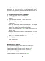
The Duty cycle is defined by the following formula, and with its results
from 0 to 1:
Duty Cycle = (Positive Pulse Width)/Period
The dutycycle mode is only available to apply on Channel 1. Moreover,
auto triggering is enabled by default for duty cycle measurement, and
the trigger levels are set to the 50% points of each signal. One may
manually disable the auto triggering and change the trigger levels and
slopes settings (refer to Ch.4.8).
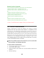
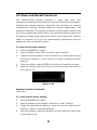
To measure Duty Cycle
1.
Connect your signal source to channel 1.
2.
Press OTHER MEAS button.
3.
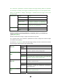
Use the first row softkey under DUTY CYC1 to select duty cycle
measurement function.
4.
Optional settings:
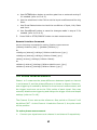
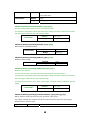
a. Use GATE&ExtArm button to set the auto or external gate time if it’s
needed (refer to Ch.4.3).
b. Use Scale&Offset button to set the scaling and offset parameters if
it’s needed (refer to Ch.4.4).
c. Use Limit Modes button set the OnFail, OUT*, Upper and Lower
limits if it’s needed (refer to Ch.4.5).
d. Use Stats button to set up the statistics function and limit filtering if
it’s needed (refer to Ch.4.6).
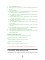
e. Use the selections in the CH1 to set the input conditions and the trig
Sens.
f. Use Show Status button to check the conditions of Input, Volt, Stats
and Limit.
g. Use Save&Recall button to save your settings (i.e., changes made in
steps a-d) if it’s needed (refer to Ch.4.9).
5.
Press RUN button to make continuous measurements.
6.
Press STOP/SINGLE button to make single measurement or to stop
continuous measurements.
25