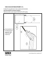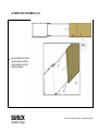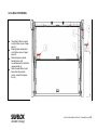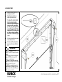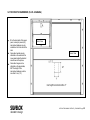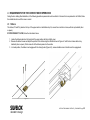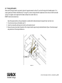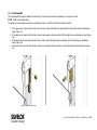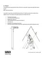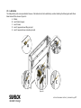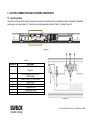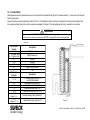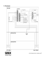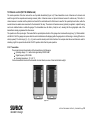
1
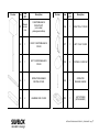
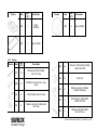
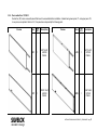
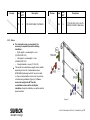
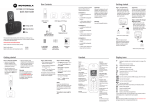
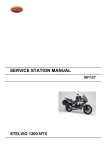
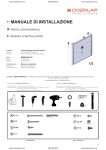
550
071
7
Silve
lox
Qual
ity
Syst
em
Rev.
06
(Sep
t
201
3)
INSTALLATION
MANUAL
Product:
door
Trento Collection - Overlap sectional garage
Model:
OVERLAP 2.0
Operation:
Manual and automatic
For Residential Use Only
Manufacturer: SILVELOX S.p.A.
I - 38050 Castelnuovo (Trento) - Viale Venezia, 37
Tel. +39 0461 755 755 Fax +39 0461 752 466
www.silvelox.com - [email protected]
TRENTO COLLECTION
©2013US
This page is intentionally left blank
INSTALLATION MANUAL OVERLAP 2_1 ENG AMARR pag.
2
TABLE OF CONTENTS
1
2
3
4
5
6
7
8
PREFACE.......................................................................................................................................................................................................................................... 4
PRELIMINARY CHECKS .................................................................................................................................................................................................................. 4
2.1
Documentation and label inventory ........................................................................................................................................................................................ 4
2.2
Box inventory .......................................................................................................................................................................................................................... 5
2.3
Tools needed ........................................................................................................................................................................................................................ 11
INSTALLATION .............................................................................................................................................................................................................................. 12
REQUIREMENTS FOR THE CORRECT DOOR OPERATION ..................................................................................................................................................... 43
4.1
Strikers.................................................................................................................................................................................................................................. 43
4.2
Closing limit switch ............................................................................................................................................................................................................... 44
4.3
Counterweights ..................................................................................................................................................................................................................... 45
4.4
Lifting arm ............................................................................................................................................................................................................................. 46
4.5
Lubrication ............................................................................................................................................................................................................................ 47
4.6
Operator ................................................................................................................................................................................................................................ 48
4.7
Current control ...................................................................................................................................................................................................................... 48
4.8
Photoeyes ............................................................................................................................................................................................................................. 48
4.9
Diagnostic LED ..................................................................................................................................................................................................................... 48
ELECTRIC CONNECTIONS AND ELECTRONIC COMPONENTS............................................................................................................................................... 49
5.1
General overview .................................................................................................................................................................................................................. 49
5.2
Terminal Block ...................................................................................................................................................................................................................... 50
5.3
Wiring Diagram ..................................................................................................................................................................................................................... 51
5.4
Door control .......................................................................................................................................................................................................................... 52
5.5
Timer-to-Close (TTC) adjustment ......................................................................................................................................................................................... 53
5.6
LEDs description .................................................................................................................................................................................................................. 53
5.7
Internal buzzer ...................................................................................................................................................................................................................... 53
5.8
Home automation contacts ................................................................................................................................................................................................... 54
5.9
Optional device prerequisites ............................................................................................................................................................................................... 54
5.10 Remote control (NOT for US&Canada) ................................................................................................................................................................................ 55
5.11 Remote control (for US&Canada)......................................................................................................................................................................................... 61
MAINTENANCE .............................................................................................................................................................................................................................. 62
DISMANTLING ................................................................................................................................................................................................................................ 62
ASSISTANCE AND ACCESSORIES ............................................................................................................................................................................................. 62
INSTALLATION MANUAL OVERLAP 2_1 ENG AMARR pag.
3
1 PREFACE
Dear customer, we want to inform you about the installation and safety procedures for a correct set-up of the Overlap garage door
designed by Silvelox. If you correctly follow all the instructions, the product will work as expected. The garage door is typically the largest
moving object in the house. Improper installation, operation or maintenance of a garage door can create a hazardous condition that can
cause serious injury or even death.
WARNING
In the interest of safety this symbol means WARNING or CAUTION. Injury to people
and/or property damage may occur unless instructions are followed correctly.
WARNING
In the interest of safety this symbol means WARNING. Injury to people and/or
property damage may occur from electrocution or fire unless instructions are
followed correctly.
2 PRELIMINARY CHECKS
Your garage door is packaged in a single crate which contains the documentation and all parts listed below. If anything is missing, carefully
check the packing material as parts may be stuck in the foam. Tools needed are also listed below.
2.1 Documentation and label inventory
Warnings labels for handling the packaging: follow the handling instructions listed on the packaging label.
Acceptance report attached to the packaging lists the contents.
Owner’s manual includes operations and maintenance instructions. Please give Owner’s Manual to the homeowner.
Installation manual instructs technicians how to install a door.
ID label describes the technical characteristics of the door and is placed on the interior side of the upper panel.
General warning label includes safety instructions for the garage door operation and is placed on the interior side of the upper panel.
Release handle warning label is placed on right counterbalance cover, just behind the release handle.
Wall control button warning label must be placed close to wall control, at least 5 feet above floor.
Electric hazard warning label indicates the danger from accidental electrocution and is placed in the proximity of the cover containing
the electric motor.
INSTALLATION MANUAL OVERLAP 2_1 ENG AMARR pag.
4
2.2 Box inventory
2.2.1
Main parts
Preview
Item
Item
QTY
Description
Item
Item
QTY
Description
U1
1
RIGHT
UPRIGHT
C1
1
OPERATOR/
HEADBAR
U2
1
LEFT
UPRIGHT
P1
1
LOWER
PANEL
Preview
INSTALLATION MANUAL OVERLAP 2_1 ENG AMARR pag.
5
Preview
Item
P2
2.2.2
Item
QTY
Description
1
UPPER
PANEL (may
include cut
out area, if
door includes
optional
decorative
hardware)
Secondary parts
Preview
Item
Item
QTY
Description
Item
Item
QTY
Description
B1
1
RIGHT NARROW
COUNTERBALANCE BOX
(color code: green)
B3
1
RIGHT LARGE
COUNTERBALANCE BOX
(color code: blue)
B2
1
LEFT NARROW
COUNTERBALANCE BOX
(color code: yellow)
B4
1
LEFT NARROW
COUNTERBALANCE BOX
(color code: red)
Preview
INSTALLATION MANUAL OVERLAP 2_1 ENG AMARR pag.
6
Preview
Item
Item
QTY
Description
Item
Item
QTY
Description
W1
Based
on door
size
COUNTERBALANCE
WEIGHT UNIT
(color coded:
yellow/green/red/blue)
C6
1
RIGHT PULLY COVER
C2
1
RIGHT COUNTERBALANCE
COVER
C7
1
LEFT PULLY COVER
C3
1
LEFT COUNTERBALANCE
COVER
C8
2
CENTRAL COVER CAP
C4
1
OPERATOR/HEADBAR
CENTRAL COVER
C9
1
OPERATOR
RELEASE HANDLE
C5
2
HEADBAR SIDE COVER
P3
1
LEFT STRIKER
(WITH MAGNET)
Preview
INSTALLATION MANUAL OVERLAP 2_1 ENG AMARR pag.
7
Preview
2.2.3
Item
Item
QTY
Description
P4
1
RIGHT
STRIKER
D1
1
50mm SPACER
Preview
Item
Item
QTY
Description
D2
4
30mm SPACER
Screws
Preview
Item
S1
S10
S2
S3
Item
QTY
Description
19
TEB AB 6,3x60 ZNG SCREW,
HEX CAP 10mm
17
8
4
S4
34
TB 5x30 C15 ZNG WOOD SCREW,
CROSS SLOTTED
S5
32
STILE CAP
S6
8
TBEI AB 6.3x16 ZN N SCREW,
SOCKET HEAD 4mm
S7
4
TB ST5,5x58-C-H ZN SCREW,
CROSS SLOTTED
S8
2
TEB AB 6,3x50 ZNG SCREW,
HEX CAP 10mm
FISCHER WALL ANCHOR, 10mm x
60mm
CONE SCREW, HEX CAP 10mm
TEB AB 6,3x16 ZNG SCREW, HEX
CAP 10mm
INSTALLATION MANUAL OVERLAP 2_1 ENG AMARR pag.
8
2.2.4
Doors wider than 10’ ONLY
Double Car (DC) doors come with panels that have to be assembled before installation. Instead having lower panel, P1, and upper panel, P2,
in one piece, as reported in Section 2.2.1, the panels are composed by the following parts:
Preview
Item
Item
QTY
Description
LP1
1
LEFT HALF
LOWER
PANEL
1
RIGHT HALF
LOWER
PANEL
RP1
Preview
Item
Item
QTY
Description
LP2
1
LEFT HALF
UPPER
PANEL
1
RIGHT HALF
UPPER
PANEL
RP2
INSTALLATION MANUAL OVERLAP 2_1 ENG AMARR pag.
9
Preview
2.2.5
Item
Item
QTY
Description
P5
4
DC DOOR PANEL TIGHTENER
Preview
Item
Item
QTY
Description
S9
8
TCEI ISO 4762 - M10 x 60 ZN
SCREW, SOCKET HEAD 8mm
Notes
The listed parts come pre-assembled; it is
necessary to separate them before starting
installation:
o Right upright + counterweights + cover
(U1+B1+B3+W1+C2)
o Left upright + counterweights + cover
(U2+B2+B4+W1+C3)
o Operator/headbar + covers (C1+C4+C5)
The quantity of counterbalance weight units is variable
depending on door size. Counterbalance boxes
(B1,B2,B3,B4) and weight units W1 are color coded,
i.e. they are marked with a common color to avoid any
confusion during installation (Figure 2-1). Please
remove the weight units W1 from the
counterbalance boxes before starting the
installation. During the installation you will be asked to
place them back.
Figure 2-1
INSTALLATION MANUAL OVERLAP 2_1 ENG AMARR pag.
10
2.3 Tools needed
Before starting the door installation, be sure to have at hand all
the tools listed below:
1.
Knife/Boxcutter
2.
4 mm Allen wrench
3.
8mm Allen wrench (for Double Car doors only)
4.
13 mm wrench
5.
10 mm spark plug wrench, 200 mm long
6.
Phillips head screwdrivers
7.
8.
9.
10.
11.
Drill, with a 3/8’’x10’’ drill bit
Tape measure
Rubber hammer
6’ ladder
Level - 24’’ or 48’’
INSTALLATION MANUAL OVERLAP 2_1 ENG AMARR pag.
11
3 INSTALLATION
IMPORTANT INSTALLATION INSTRUCTIONS
WARNING: To reduce the risk of severe injury or death
1.
2.
READ AND FOLLOW ALL INSTALLATION WARNINGS AND
INSTRUCTIONS before to install, operate, perform
maintenance or repair the garage door.
7.
Install wall-mounted garage door control:
within sight of the garage door.
out of reach of children at minimum height of 5 feet (1.5 m).
Install garage door opener ONLY on properly balanced and
lubricated garage door. An improperly balanced door may not
reverse when required and could result in SEVERE INJURY or
DEATH.
8.
Place entrapment warning label on wall next to garage door
control.
3.
Disable ALL locks and remove ALL ropes connected to garage
door BEFORE installing opener to avoid entanglement.
9.
Place manual release/safety reverse test label in plain view on
inside of garage door.
4.
Mount emergency release handle 6 feet (1.8 m) above floor.
5.
NEVER connect garage door opener to power source until
instructed to do so.
10. Upon completion of installation, test safety reversal system.
Door MUST reverse on contact with a 1-1/2" (3.8 cm) high
object (or a 2x4 laid flat) on the floor.
6.
NEVER wear watches, rings or loose clothing while installing
or servicing garage door. They could be caught in garage door
or opener mechanisms.
11. To avoid SERIOUS PERSONAL INJURY or DEATH from
electrocution, disconnect ALL electric and battery power
BEFORE performing ANY service or maintenance.
away from ALL moving parts of the door.
INSTALLATION MANUAL OVERLAP 2_1 ENG AMARR pag.
12
DOUBLE CAR (DC) DOOR PANEL SUPPLEMENT (1 of 3)
If installing a DC door (door width larger than 10’ wide), assemble the panels before installation.
Upper panel assembly ONLY is presented in this supplement.
Repeat the same steps for lower panel, replacing LP2 and RP2 with LP1 and RP1 respectively.
Screw the two tighteners, P5, in
the threaded holes of left half
upper panel LP2. Detailed
ilustration shows upper
threaded hole only.
INSTALLATION MANUAL OVERLAP 2_1 ENG AMARR pag.
13
DC DOOR PANEL SUPPLEMENT (2 of 3)
Insert the tighteners P5 into the
right half upper panel, RP2 by
carefully sliding the right half
and left half together.
INSTALLATION MANUAL OVERLAP 2_1 ENG AMARR pag.
14
DC DOOR PANEL SUPPLEMENT (3 of 3)
LP2
RP2
Secure the panel using four S9
screws.
NOTE: Fasten the S9 screws
tightly.
Repeat the same steps of the
supplement for lower panel,
replacing LP2 and RP2 with LP1
and RP1 respectively.
INSTALLATION MANUAL OVERLAP 2_1 ENG AMARR pag.
15
3.1 WALL OPENING
Wood door jambs and 2X6
center pad must frame the door
opening (#2 grade or better).
Measure opening width, X.
Check that floor is level.
NOTE: Wood door jambs are
ONLY shown in this installation
step. Assume jambs are
present in all successive steps.
In case of a concrete or brick
wall, see page 18 for
installation instructions.
INSTALLATION MANUAL OVERLAP 2_1 ENG AMARR pag.
16
3.2 RIGHT UPRIGHT
Place the first upright, starting
from the highest side of the
floor.
Determine the width of the
external frame, reference Y
according the following rule:
Y=(Z-X)/2
where Z is the width of the
external frame plus the opening
width (approximately 11’’ to
nominal door width), and X is
the door opening width.
E.g.: if installing an 8’ wide
door, Z = 8’11’’
INSTALLATION MANUAL OVERLAP 2_1 ENG AMARR pag.
17
3.3 RIGHT UPRIGHT SECURING
Secure the upright using the
horizontal shaped hole as in
the picture.
Attach upright to wall using
screw S1.
In case of a concrete or brick
wall installation, insert a
Fisher anchor, S10, in the
wall hole.
Final attachment + adjustment
will come later.
INSTALLATION MANUAL OVERLAP 2_1 ENG AMARR pag.
18
3.4 LOWER PANEL
Place panel P1 in the opening.
Use spacer D1 to level the
panel
Attach P1 to upright using two
S2 fasteners, starting with the
top hole.
INSTALLATION MANUAL OVERLAP 2_1 ENG AMARR pag.
19
3.5 UPPER PANEL
Before placing the panel, P2,
put the spacers D2 above the
lower panel 12” from each end.
Place panel P2 on top of P1
and the spacers.
Fasten P2 to the upright with
two S2 fasteners.
P1
NOTE: If your door will use outside
decorative handles, then the upper
panel will have a box on the interior
(not shown).
INSTALLATION MANUAL OVERLAP 2_1 ENG AMARR pag.
20
3.6 STRIKERS ON UPPER PANEL
Place the strikers, P3 and P4,
in the positions indicated by the
pre drilled holes located on top
of the upper panel.
Fasten the strikers with S7
screws
NOTE: P3 on the left side has
a magnet.
NOTE: Screws S7 are 58 mm
long. Do not confuse with
screws S4, which are 30 mm
long.
INSTALLATION MANUAL OVERLAP 2_1 ENG AMARR pag.
21
3.7 OPERATOR/HEADBAR
Place the operator/headbar C1
on top of the upper panel.
Attach C1 to one of the uprights
with two screws S3.
NOTE: Be sure the headbar
latches are aligned with the
panel strikers, P3 and P4, and
the pin placed in the middle of
the upper panel P2 is centered.
INSTALLATION MANUAL OVERLAP 2_1 ENG AMARR pag.
22
3.8 PHOTOEYE, OPERATOR RELEASE AND STRAP CONNECTION
Plug in the photo-eye cable (A):
purple wire in slot 16 (dot), grey
wire in slot 13 (square), pink
wire in slot 16 (cross), and blue
wire in slot 12 (triangle) of the
CN1 terminal block.
Attach the release handle cable
(B) to the latch (C)
Pull the strap in the middle of
the operator/headbar and
attach it to the upper panel by
pushing it through the screws
present on the upper side of
the panel (D). Additional screw
tightening may be necessary.
NOTE: See Section 6.2 for
connection details.
INSTALLATION MANUAL OVERLAP 2_1 ENG AMARR pag.
23
3.9 LEFT UPRIGHT
Put the remaining upright U2 in
place.
In the case of an uneven floor,
add spacers below the upright
base (A), to level this upright
with respect to the other
upright.
Attach the upright using the
vertical shaped hole with screw
S1.
In case of a concrete or brick
wall installation, use a Fisher
anchor, S10.
INSTALLATION MANUAL OVERLAP 2_1 ENG AMARR pag.
24
3.10 PANEL AND OPERATOR/HEADBAR ATTACHMENT
Secure the upper and lower
panels to the second upright by
fastening two S2 screws in the
upper panel P2 and in the
lower panel P1, in the same
manner as step 3.5
Secure the headbar to the
upright with two S3 fasteners in
the same manner as step 3.7
INSTALLATION MANUAL OVERLAP 2_1 ENG AMARR pag.
25
3.11 PHOTOEYE AND LIMIT SWITCH CONNECTION
Connect the photo-eye cable
(A): plug the two wires in slot 15
and 14 of the CN1 terminal
block (dots).
NOTE for US & Canada: If
provided, connect and install an
external receiver. Plug the
power wires in slot 13 and 12 of
the CN2 terminal block
(crosses). Plug the Channel1
wires in slot 8 and 2 of the CN1
terminal block (triangles). See
Sections 6.9 and 6.11 for
additional information.
NOTE: See Section 6.2 for
additional details about the
terminal block.
INSTALLATION MANUAL OVERLAP 2_1 ENG AMARR pag.
26
3.12 SPACER REMOVAL
Remove the spacers between
the panels and any spacers on
the floor.
INSTALLATION MANUAL OVERLAP 2_1 ENG AMARR pag.
27
3.13 LEVEL THE OPERATOR/HEADBAR
Check operator/headbar level.
To level, adjust the second
installed upright fixed through
the vertical shaped hole.
INSTALLATION MANUAL OVERLAP 2_1 ENG AMARR pag.
28
3.14 SECURING THE OPERATOR/HEADBAR
Once level, attach the
operator/headbar to the wall
with three S1 screws.
In case of a concrete or brick
wall installation, use a Fisher
anchor, S10.
INSTALLATION MANUAL OVERLAP 2_1 ENG AMARR pag.
29
3.15 UPRIGHT LEVEL AND ATTACHMENT
Check the level of the upright
and secure to the wall with five
S1 screws each.
Repeat for other upright.
In case of a concrete or brick
wall installation, use a Fisher
anchor, S10
INSTALLATION MANUAL OVERLAP 2_1 ENG AMARR pag.
30
3.16 NARROW COUNTERBALANCE BOXES
Place the narrow
counterbalance boxes (without
the weights in them): B1(green)
on the right and B2 (yellow) on
the left .
Hang the counterbalance boxes
on to the two cables ending with
a sphere (solid black in the
zoomed detail).
NOTE: There are no screws to
fasten. The cable spheres
simply go in their housing
placed in the upper part of the
counterweight boxes.
NOTE: Make sure to follow the
color code.
The open side of the box will
face the side of the garage, as
shown in the picture (see also
installation step 3.17).
INSTALLATION MANUAL OVERLAP 2_1 ENG AMARR pag.
31
3.17 WEIGHT LOADING – NARROW BOXES
Load the narrow counterbalance
boxes with the weight units W1.
NOTE: Make sure to follow the
color code: green W1 for right
counterbalance box, B1; yellow
W1 for left counterbalance box,
B2.
INSTALLATION MANUAL OVERLAP 2_1 ENG AMARR pag.
32
3.18 LARGE COUNTERBALANCE BOXES AND CABLES
Place the two cables attached
to the lower panel around the
pulleys (as indicated by the
arrows: in the right side, the
cable is shown still wrapped; in
the left side, the cable is shown
in the installed configuration).
Hang the large counterbalance
boxes, B3 (blue) and B4 (red),
without the weights, to the
sphere extremities of the
cables, in the same way done
for boxes B1 and B2.
NOTE: Make sure to follow the
color code.
INSTALLATION MANUAL OVERLAP 2_1 ENG AMARR pag.
33
3.19 WEIGHT LOADING – LARGE BOXES
Load the counterbalance boxes
with the weight units W1.
NOTE: Make sure to follow the
color code: blue W1 for right
counterbalance box, B3; red
W1 for left counterbalance box,
B4.
.
INSTALLATION MANUAL OVERLAP 2_1 ENG AMARR pag.
34
3.20 OPERATOR DRIVE SHAFTS
The drive shafts are already
present in the headbar
assembly.
Plug them in the appropriate
upright joint (both sides).
NOTE: In the zoomed detail,
the left side is depicted. The
arrow shows where to insert
the drive shaft. The upright joint
has to be pushed back to allow
the insertion of the drive shaft;
the spring of the joint will
restore its position after the
engagement.
INSTALLATION MANUAL OVERLAP 2_1 ENG AMARR pag.
35
3.21 PANEL ADDITIONAL SECURING
Using screws S4, attach the
panels to the frame.
There are 16 screws for each
side.
Remember to fasten both
sides.
INSTALLATION MANUAL OVERLAP 2_1 ENG AMARR pag.
36
3.22 STILE CAPS
Cover the screws placed in
step 3.21 with 16 stile caps, S5,
on each side.
INSTALLATION MANUAL OVERLAP 2_1 ENG AMARR pag.
37
3.23 COVERS AND RELEASE HANDLE
Put the covers in place
following this order:
C3
LEFT COUNTERBALANCE
COVER
C7
LEFT PULLY COVER
C2
C9
RIGHT COUNTERBALANCE
COVER
OPERATOR
RELEASE HANDLE – Attach
to the tab coming out from
the pulley box (A).
C6
RIGHT PULLY COVER
C5
HEADBAR SIDE COVER
C4
OPERATOR/HEADBAR
CENTRAL COVER
C8
CENTRAL COVER CAP
INSTALLATION MANUAL OVERLAP 2_1 ENG AMARR pag.
38
3.24 COVER SECURING AND PHOTO-EYE HANGING
Using six screws S6, fix the
operator/headbar covers to the
frame.
Hang the photo-eyes on the
counterbalance boxes; details
(A) shows the left side. Do the
same for right side too.
NOTE: Photo-eyes are included in
the upright assemblies, U1 and U2.
Hang them on to the circular slots
of counterbalance boxes, C2 and
C3.
INSTALLATION MANUAL OVERLAP 2_1 ENG AMARR pag.
39
3.25 LABEL POSITIONING
Check that ID label is in place
on right bottom corner of upper
panel (1).
Attach general warning label
on left bottom corner of upper
panel (2).
Attach emergency release
handle label on right
counterbalance box, behind the
release handle (3).
Attach the wall station control
button label close to wall
control, at least 5 feet above
floor (4).
INSTALLATION MANUAL OVERLAP 2_1 ENG AMARR pag.
40
3.26 DOOR TEST
Remove the two blocks, D2, by
releasing screws S8.
Plug the power cable in a
properly grounded outlet.
To reduce the risk of electric
shock, your garage door
opener has a grounding type
plug with a third grounding
pin. This plug will only fit into
a grounding type outlet. If the
plug doesn’t fit into the outlet
you have, contact a qualified
electrician to install the proper
outlet.
Test door manually (see owner’s
manual, Section 3.1).
Test door with the transmitter
(see owner’s manual, Section
3.2).
WARNING
To prevent possible SERIOUS
INJURY or DEATH from electrocution
or fire:
• Disconnect ALL electric and battery
power BEFORE performing ANY
service or maintenance.
• Garage door installation and wiring
MUST be in compliance with ALL local
electrical and building codes.
• NEVER use an extension cord, 2wire adapter, or change plug in ANY
way to make it fit the outlet. Be sure
the opener is grounded.
INSTALLATION MANUAL OVERLAP 2_1 ENG AMARR pag.
41
3.27 DECORATIVE HARDWARE (for US & CANADA)
If on the back side of the upper
panel, a cavity is present (A),
decorative hardware may be
installed on the front side of the
door.
Decorative handles can be
attached on the outside of the
lower panel inside the dashed
area shown in the picture.
Decorative hinges can be
attached on the panel sides,
BUT the height of the
decorative hardware must be
less than 7 mm (1.5”).
Interior View
Exterior View
INSTALLATION MANUAL OVERLAP 2_1 ENG AMARR pag.
42
4 REQUIREMENTS FOR THE CORRECT DOOR OPERATION
During the door testing after installation, all the following operation requirements must be verified. In the case that a requirement is not fulfilled, follow
the related instruction until the issue is solved.
4.1 Strikers
The strikers, P3 and P4, placed on the top of the upper section in installation step 3.6, ensure the correct door closure, without any backlash (door
re-opens).
IF DOOR DOES NOT CLOSE, follow the instructions below:
1. Locate the strikers placed on the top side of the upper section with door slightly open;
2. Release the striker screws and adjust the position of the striker along the direction shown in Figure 4-1 until the door closes without any
backlash (door re-opens). Do the same for all the strikers present on the section.
3. In closed position, the strikers must engage with the closing hooks (Figure 4-2); remove headbar covers to better see the engagement.
Figure 4-1
Figure 4-2
INSTALLATION MANUAL OVERLAP 2_1 ENG AMARR pag.
43
4.2 Closing limit switch
Make sure the closing limit switch, composed by the pair of magnates mounted on striker, P3, and on left closing latch of headbar/operator, C1, is
properly placed (see P3 detail of installation step 3.7 on page 22). In case of closing limit switch misplacement, the door does not start the automatic
opening. The magnets must be aligned and the distance between them smaller than 6 mm.
IF NOT, follow the instructions below:
Adjust the magnets positions until a good alignment is reached and the distances between the magnets faces is less than 6 mm.
1. Close the door and remove left headbar cover C5.
2. Locate the closing limit switch placed on the latch near the electronic board.
3. Release the screw (A) and adjust the position of the closing limit switch magnet along the indicated direction (Figure 4-3) and align magnet
along dashed line. Check magnet distance too.
Figure 4-3
INSTALLATION MANUAL OVERLAP 2_1 ENG AMARR pag.
44
4.3 Counterweights
The counterweights are properly balanced from the factory. This results in a smooth door operation, nor too slow nor too fast.
IF NOT, follow the instructions below:
To balance the counterweights, remove the counterbalance covers, C2 and C3, and follow the instructions below:
1. If the upper section in open position tends to drop: with door closed, add weight units symmetrically to left and right narrow counterbalance
boxes (Figure 4-4)
2. If the upper section opens too fast: with door closed, remove weight units symmetrically to left and right narrow counterbalance boxes (Figure
4-4)
3. If the lower section in open position tends to drop: with door closed, add weight units symmetrically to left and right large counterbalance
boxes (Figure 4-5)
4. If the lower section opens too fast: with door closed, remove weight units symmetrically to left and right large counterbalance boxes (Figure
4-5)
Figure 4-4 Right side only shown
Figure 4-5 Right side only shown
INSTALLATION MANUAL OVERLAP 2_1 ENG AMARR pag.
45
4.4 Lifting arm
The lifting-arm upper joint is properly located from the factory. When the door is in open position, the upper section is slightly tilted as showed in
Figure 4-6..
IF NOT, follow the instructions below:
In open position, the upper section must be slightly tilted as showed in Figure 4-6. To adjust the upper section incline, the position of the pin
highlighted in Figure 4-7 with a dashed line must be adjusted. Adjust the pin on both sides with door closed.
1.
2.
3.
4.
5.
6.
7.
Close the door and unplug opener;
Locate the lifting arm pin on the headbar corner;
Release the pin nut, A (Figure 4-7);
Tighten the adjustment screw, B, to create more incline (Figure 4-7);
Secure the pin nut, A;
Repeat steps 3 to 5 for the pin placed on the other side;
Open the door and check the inclination of the upper section; repeat these steps until a slightly tilted configuration is reached.
Figure 4-6
Figure 4-7
INSTALLATION MANUAL OVERLAP 2_1 ENG AMARR pag.
46
4.5 Lubrication
The sliding/rotation parts come pre-lubricated. However, if lubrication should not be satisfactory, consider lubricating the following parts with Lithium
Base Grease EP2 as shown in Figure 4-8:
A. Strikers;
B. L and R cable hangers;
C. L and R rollers;
D. L and R, upper and lower lifting arm joint;
E. L and R, upper and lower connecting arm joint.
Figure 4-8
INSTALLATION MANUAL OVERLAP 2_1 ENG AMARR pag.
47
4.6 Operator
Operator control parameters are set correctly which results in a smooth door operation.
IF NOT, see adjustments instructions of Section 5.4.
4.7 Current control
The "Amperostop" current control system works by blocking and reversing the door in presence of obstacles. To test this device, with the door fully
open, place a 1-1/2" thick piece of wood (a 2" X 4" laid flat) on the floor in the center of the door. Push the transmitter or wall button to close the
door. The door must reverse when it strikes the obstruction. Reset maneuver will follow (see user manual Section 3.4).
IF NOT, contact Silvelox Customare Care.
4.8 Photo-eyes
The photo-eyes work by blocking and reversing the door in presence of obstacles between them. To test this system, standing inside the garage, but
safely away from the path of the door, use the remote control or wall button to close the door. As the door is closing, wave an object in the path of
the photoelectric eye beam. If door stops and reverses, the system works correctly. Reset maneuver will follow (see user manual Section 3.4).
IF NOT, contact Silvelox Customare Care.
4.9 Diagnostic LED
The Diagnostic LED (Figure 5-2 on page 49, referenced as number 4) works without signaling any anomalies, i.e. it does not blink.
IF NOT, contact Silvelox Customare Care.
INSTALLATION MANUAL OVERLAP 2_1 ENG AMARR pag.
48
5 ELECTRIC CONNECTIONS AND ELECTRONIC COMPONENTS
5.1 General overview
The electric connections and the electronic components are located in the operator control box, immediately visible on the headbar, if the headbar
central cover is not in place (Figure 5-1). The electric connections/components are listed in Table 5-1, referring to Figure 5-2.
Figure 5-1
Table 5-1
Reference
1
Description
Terminal Block (see
Figure 5-3)
2
3
4
5
6
7
/
Built-in Receiver Controls (NOT for
USA&Canada)
Timer-to-Close (TTC) Control Button
Diagnostic LED
Voltage LED
Configuration Port
Courtesy Light LEDs
Internal Buzzer (not visible)
Figure 5-2
INSTALLATION MANUAL OVERLAP 2_1 ENG AMARR pag.
49
5.2 Terminal Block
Safety appliances and/or optional devices have to be connected to the terminal blocks (Figure 5-2 reference number 1). A close view of the terminal
blocks is presented in
Figure 5-3 and the contact descriptions are listed in Table 5-2. To facilitate the cable connections it is possible to remove the terminal blocks from
their sockets and place them back once the connections are placed. In Section 5.3 the wiring diagram can help to visualize the connections.
WARNING
To prevent possible SERIOUS INJURY or DEATH from electrocution or fire:
• Disconnect ALL electric and battery power BEFORE connecting ANY cable to the terminal block.
Table 5-2
CN1 Contacts
(Inputs)
15 - 14
16 – 13 (purple - grey)
16 – 12 (pink - blue)
8-7
8-5
8-4
8-2
8-1
CN2 Contacts
(Outputs)
Description
Left Photoeye (tx)
Right Photoeye (rx)
Close NO
Stop NC
Open NO
Open / Stop / Close NO
NC
Description
nd
11 - 10
9-8
7-6
7-5
13 -12
13 – 1
bridge 12 - 2
13 – 3
bridge 12 – 4
2 Channel Built-in Receiver FC
(not for USA&Canada)
External Buzzer (Optional) FC
Home Automation output 1 FC
Home Automation output 2 FC
Power 24 Vdc (max 500 mA, 12 W)
External Flashing Light (Optional) FC
Supplementary Light (Optional) FC
Figure 5-3
INSTALLATION MANUAL OVERLAP 2_1 ENG AMARR pag.
50
5.3 Wiring Diagram
INSTALLATION MANUAL OVERLAP 2_1 ENG AMARR pag.
51
5.4 Door control
The operator parameters listed in Table 5-3 can be controlled using a control kit, composed by a Bluetooth key and a dedicated iOS App, available
only to qualified technicians.
With door closed and connected to the power network, plug the Bluetooth key in the configuration port visible in Figure 5-2, referenced as
number 6;
Start the App from your portable device and follow the instructions provided within the control kit.
Table 5-3
Operator parameters controlled by the dedicated iOS App
Current absorption during operation phases (opening start, opening finish, closing start, closing finish, latch release, panel engagement, cruise)
Current phase timing
Opening/Closing cycle duration
Strap pulley timing
Drive shaft pulley timing
Photoeye timing
TTC setting
Courtesy light setting
External flashing light setting
External buzzer setting
INSTALLATION MANUAL OVERLAP 2_1 ENG AMARR pag.
52
5.5 Timer-to-Close (TTC) adjustment
By default, TTC is set to off. TTC can be set to automatically close your garage door from the fully open position after a specified period of time
(1,3,5 or 10 minute intervals). The garage door opener will Beep and the courtesy light will Flash before closing the door.
To set TTC, please follow the instructions below:
With door closed and connected to the power, remove the headbar central cover;
Keep pressed for 3 seconds the TTC Control Button (Figure 5-2 on page 49, referenced as number 3); the Diagnostic LED (Figure 5-2 on page
49, referenced as number 4) will blink 2 times;
Press the TTC Control Button to set 1 minute closing interval; the Diagnostic LED will blink 1 time;
Press the TTC Control Button, within 10 seconds from the last operation, to set 3 minutes closing interval; the Diagnostic LED will blink 2 times;
Press the TTC Control Button, within 10 seconds from the last operation, to set 5 minutes closing interval; the Diagnostic LED will blink 3 times;
Press the TTC Control Button, within 10 seconds from the last operation, to set 10 minutes closing interval; the Diagnostic LED will blink 4 times;
Press the TTC Control Button, within 10 seconds from the last operation, to set to off the TTC; the Diagnostic LED will blink 5 times;
After 10 seconds from the last selection made, the TTC is set.
WARNING
In case of a voltage interruption during opening or closing, once the voltage is restored, the
door remains in the actual position. Close the door manually or perform the reset maneuver
(see user manual Section 3.4).
5.6 LEDs description
A total of six LEDs are present in the operator control unit box:
The Diagnostic LED (Figure 5-2 on page 49, referenced as number 4): it starts to blink (red color) in case of electronic anomalies;
The Voltage LED (Figure 5-2, referenced as number 5): it turns ON (green color) once the door is plugged to the power network;
The Courtesy Light LEDs (Figure 5-2, referenced as number 7): it is a group of four white LEDs; once the door is activated, they turn ON and stay
ON for 1 minute after that the door operation is completed.
5.7 Internal buzzer
The operator control box is equipped also with an internal buzzer. When the door performs a reset maneuver (see user manual Section 3.4), the
internal buzzer will beep for the whole maneuver signaling that the current control is set to a higher, potentially dangerous level and to allow the
door to re-define its reference positions.
INSTALLATION MANUAL OVERLAP 2_1 ENG AMARR pag.
53
5.8 Home automation contacts
Two home automation free contacts (FCs) are present on the terminal block CN2 (Figure 5-3 on page 50). Use these contacts to connect the door to
home automation system.
Home automation 1 is active when the door is opening;
Home automation 2 is active when the door is closing;
When the door is operated manually or during a reset operation, the contacts are open.
5.9 Optional device prerequisites
The following optional devices can be installed by the dealer:
External buzzer
External flashing light
Supplementary light
External receiver
These accessories have to be connected on the relays of the terminal block CN2 (see Table 5-2 and Wiring diagram of Section 6.3).
The specifics of the relays are:
Max 1 A @ 125 Vac (resistive load)
Max 1 A @ 30 Vdc (resistive load)
Max 500 mA @ 230 Vac (resistive load)
Max 500 mA @ 125 Vac (inductive load)
Max 250 mA @ 230 Vac (inductive load)
Minimum load: 5 V, 10 mA
In the Wiring diagram of Section 6.3, the flashing light and the supplementary light are powered by the contacts 13-12.This is only a possibility; in
this case the absorption of the connected devices cannot exceed the capacity of the power contacts 13-12, which is: 24 Vdc, max 500 mA (12 W).
An external source of power might be preferable.
INSTALLATION MANUAL OVERLAP 2_1 ENG AMARR pag.
54
5.10 Remote control (NOT for US&Canada)
The remote operation of the door involves the use of portable transmitters (Figure 5-4). These transmitters can be 2-channels or 4-channels and
send the signal to the respective auto-learning receivers (built-in 2-channel receiver or optional 4-channel receiver for outdoor use). The built-in 2channel receiver is mounted onto the printed circuit board of the motorization and its first channel is used for the open/stop/close function, while the
second channel is useable when connected to the terminals of the relay. The external 4-channels receiver (optional) is supplied in a plastic housing
and can be installed inside or outside the garage. The transmitters leave the factory “ready for use”, meaning that the cryptographic code of the
transmitter is already programmed into the receiver.
The operation is of the impulse type. This means that the open/stop/close function of the garage door is made with a single key (1) of the transmitter:
with the first “click” the garage door opens while the next click determines the stopping (while the garage door is still moving) or closing (if the door is
entirely opened). The other keys ((2) – (3) – (4)) can be used to remotely control other functions. For example when the second channel is used for
activating a light it is required to activate the ON-OFF operation rather than the pulse operation.
5.10.1 Transmitters
The principal technical characteristics of the transmitters are the followings:
Operating voltage: 3 V = with a button type battery CR2032 LiMn
Signal frequency: 433.92 MHz
Operating temperature: -10 / +55 ° C
It is recommended to not submit the transmitter to violent shocks, sources of heat and to direct sunlight.
Figure 5-4
INSTALLATION MANUAL OVERLAP 2_1 ENG AMARR pag.
55
5.10.2 Built-in 2-channel receiver
The 2-channel receiver controls are accessible through the hole in the control unit box (Figure 5-2 referenced numbers 2 and 3). A closer
view of them is presented in Figure 5-5, with their description in Table 5-4. The receiver can support 150 transmitters maximum.
To activate the 2nd channel, connect the external device cables to slot 11-10 of the CN2 terminal block (Figure 5-3).
Table 5-4
Reference
i
ii
A
B
C
D
Description
Jumper to assign the button (1) of the
transmitter (operation already performed at
the factory)
Jumper to assign the button (2) of the
transmitter (operation already performed at
the factory)
Jumper to entirely cancel all and functions
of the receiver (Reset)
Jumper to block all functions
Jumper to indicate how many transmitters
are memorized
Self-learning button
Figure 5-5
INSTALLATION MANUAL OVERLAP 2_1 ENG AMARR pag.
56
5.10.3 4-channel receiver (OPTIONAL)
The external 4-channels receiver is mounted in an ABS plastic housing for an optimal protection against atmospheric agents. It can
work together with the 2-channels receiver present on the door, to offer the maximum number of remotely controlled devices. Please
refer to Figure 5-6, Table 5-5 and Table 6-6 for a detailed view and description of the receiver components.
It is possible to fasten the receiver to a wall or on a pole (or a suitable bracket); ensure that the supply voltage is either 12 or 24V DC.
If problems are encountered with signals reception, it is necessary to install an external antenna which is available on request. The
antenna must be installed at the highest point possible and in an area which is free of obstacles. The optimal efficiency is obtained when it
is installed on a metal pole or concrete, avoiding materials such as wood or plastic. When the length of the included cable is insufficient, it
is recommended to replace it entirely with a low losses coaxial cable with an impedance of 52 Ohm (type RG58/U) and to not exceed a
length of 10 meters.
Table 5-5
Reference
1 to 12
13 - 14
i
ii
iii
iv
A
B
C
D
E
Description
Receiver terminal block
Output terminals for antenna connection
(see Table 5-6, page 58)
Jumper to assign a button of the
transmitter to the relay 1
Jumper to assign a button of the
transmitter to the relay 2
Jumper to assign a button of the
transmitter to the relay 3
Jumper to assign a button of the
transmitter to the relay 4
Jumper to entirely cancel all and
functions of the receiver (Reset)
Jumper to block all functions
Jumper to indicate how many
transmitters are memorized
Self-learning button
Red LED
Figure 5-6
NOTE: The buttons (1) and (2) of the transmitter are assigned respectively to the first and second channel of the built-in 2-channel
receiver.
INSTALLATION MANUAL OVERLAP 2_1 ENG AMARR pag.
57
In Table 5-6 please find the description of the 4-channel receiver terminal block.
Table 5-6
CONTACTS
DESCRIPTION
1 -2
Power input 12 / 24 Vdc/Vac; terminal 1= (-) ; terminal 2= (+)
When 12V power is used, it is necessary to insert the jumper close to the terminal
3 -4
NO relay 1
4 -5
NC relay 1
6 -7
NO relay2
7 -8
NC relay 2
9 -10
NO relay 3
11 -12
NO relay 4
13
Coaxial antenna – shield
14
Coaxial antenna – core
WARNING
Devices connections must be carried by an accredited technician.
The wiring must be done using cable of 2 x 1 mm2 / max 40 W (relay 1-2-3) or 100 W (relay 4).
INSTALLATION MANUAL OVERLAP 2_1 ENG AMARR pag.
58
5.10.4 Operation of the receivers (2- and 4-channels)
ON/OFF Mode
The standard operating mode of the transmitter-receiver system is of the impulse type. In other words, when one of the keys of the
transmitter is pressed, the corresponding relay on the receiver is closed and when the key is released, the relay is opened again.
In some situations, however, it may be preferable to activate the relay when the key is pressed for the first time, and that it stays activated
until the key is pressed again, especially when it is used to activate lighting.
This mode of operation is called “ON-OFF”. To activate this mode it is required to install a permanent bridge on the jumper of the
corresponding relay (see Figure 5-5 and Figure 5-6).
WARNING! Never leave a permanent bridge on jumper referenced as “i” in Figure 5-5 of the 2-channel receiver.
Blocking mode
This mode is activated when a permanent bridge is inserted in jumper B of the receiver (see Figure 5-5 and Figure 5-6). In this mode it is no
longer possible to insert a code from a distance, activate the ON-OFF mode, or cancel a code.
De-activation of a pushbutton of a transmitter
If necessary it is possible to de-activate the function attributed to a key of a transmitter.
To de-activate the function, proceed as follows:
Remove the bridges that may be present on the jumpers of the receiver.
Press the self-learning button of the receiver and keep it pressed.
Press the pushbutton of the transmitter that must be cancelled.
Keep the pushbutton pressed until the red LED on the receiver illuminates.
Release the pushbutton of the transmitter and then the self-learning button.
De-activation of all transmitters (Reset)
In case of theft or disappearance of a transmitter, it is recommended to de-activate the functions of all transmitters in order to avoid
unpleasant consequences, by following the steps below:
Insert the bridge on jumper A of the receiver.
Press the self-learning button of the receiver for at least 7 seconds.
Release the self-learning button.
Wait until the red LED on the receiver is illuminated.
Remove the bridge of jumper A and place it on the adjacent free pin of the jumper.
NOTE: this operation must be performed both for the internal 2- and 4- channel receivers.
INSTALLATION MANUAL OVERLAP 2_1 ENG AMARR pag.
59
Restoring the functions of the transmitter keys and restoring another code (2-channel receiver)
Verify that the garage door is connected to the mains.
Insert the bridge on jumper “i” (see Figure 5-5).
Press the self-learning key, D, and keep it pressed.
Press key (1) of the transmitter and keep it pressed.
Wait until the red LED illuminates, then first release the key of the transmitter followed by releasing the self-learning button.
Remove the bridge of jumper “i” of the 2-channel receiver.
When the second channel is used, repeat the operations from point 2 to 6 for jumper “ii” and key (2).
Put the bridge on the adjacent free pin of the jumper.
Restoring the functions of the transmitter keys and restoring another code (4-channel receiver)
Verify that the 4-channels receiver has power on the terminals 1-2 (12-24V DC/AC).
Insert the bridge on jumper “i” (see Figure 5-6).
Press the self-learning key, D, and keep it pressed.
Press the free key on the transmitter which will control relay 1 and keep it pressed.
Wait until the red LED, E, lluminates, then first release the key of the transmitter followed by releasing the self-learning button D.
Remove the bridge of jumper “1” of the 4-channels receiver.
Repeat, if necessary, operations from point 2 to 6 for the next jumpers and free keys on the transmitter.
When the assignment of all functions and keys is accomplished, put the bridge on the adjacent free pin of the jumper.
To re-program other transmitters, refer to the instructions in the next paragraph “Activating a new transmitter”.
Activating a new transmitter
It is necessary to have a transmitter that is already functioning and programmed (named “original transmitter”).
De-activate eventual other receivers installed in the vicinity, by temporarily cutting power.
Stand within 15 feet from the garage door.
Press (1) and (2) together of the original transmitter.
Within 5 seconds, press a key of the transmitter to be activated.
For eventual other transmitters, repeat the steps described above.
INSTALLATION MANUAL OVERLAP 2_1 ENG AMARR pag.
60
5.11 Remote control (for US & Canada)
The operator is compatible with the Liftmaster 3-Channel Universal Receiver 850 LM which can be connected inside the headbar. The main features
of the 850LM are:
Three channels provide expanded remote control capacity: Channel 1 - 50 remotes, Channel 2 - 20 remotes, Channel 3 - 20 remotes
Multiple remote control options available to provide secure access from the safety and convenience of a vehicle
Compact design fits most gate and commercial door operators
Compatible with 811LM and all MAX remote controls
Power: 12-24VDC or 12-24VAC
Narrow-band on 310 MHz, 315 MHz, and 390 MHz Security+ 2.0™ Rolling Code and Encrypted DIP
Operational temperature from -35 to 65 degrees C; Storage temperature from -40 to 85 degrees C
Compliant with FCC Part 15
INSTALLATION MANUAL OVERLAP 2_1 ENG AMARR pag.
61
6 MAINTENANCE
For any further detail on the maintenance procedures, read the user manual.
7 DISMANTLING
In case of dismantling, it is necessary to lock the door and disconnect some components to make the door unusable, as: counterweights
boxes, pulleys and power plug. To discard, please contact an accredited company following local laws and regulations.
8 ASSISTANCE AND ACCESSORIES
Dear Customer, Silvelox is available for any further explanation. We remind you that in case you will need the assistance of a qualified
technician or you will consider to install new accessories for your garage door, you can contact the Silvelox Customer Care. With the purpose
to speed up the handling of your inquiry, please provide the serial number of your door (placed in the label above the inner door handle) and
fill the suitable form available at www.silvelox.com, in the Customer Service page.
SILVELOX S.p.A.
Italy-38050 Castelnuovo (Trento) - Viale Venezia, 37
Tel. +39 0461 755 755 - Fax +39 0461 752 466
[email protected]
INSTALLATION MANUAL – MD.75.1.XX
ISSUED BY SILVELOX TECHNICAL OFFICE
APPROVED BY
INSTALLATION MANUAL OVERLAP 2_1 ENG AMARR pag.
62
This page is intentionally left blank
INSTALLATION MANUAL OVERLAP 2_1 ENG AMARR pag.
63
Although the commitment for the accuracy of all the
information included in the present manual, Silvelox
declines any responsibility for any possible errors,
imprecisions and omissions. Information in this
document is subject to change without notice.
All rights reserved. No part of this manual can be
reproduced, copied and transmitted for any purposes
without the express prior written consent of Silvelox.
SILVELOX S.p.A.
Italy-38050 Castelnuovo (Trento) - Viale Venezia, 37
Tel. +39 0461 755 755 - Fax +39 0461 752 466
[email protected]