1
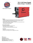
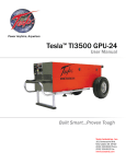
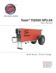
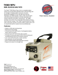
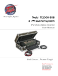
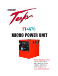
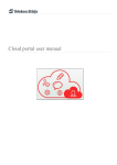
Power Anytime, Anywhere Tesla™ TI50A DC Power Supply User Manual Built Smart...Proven Tough Tesla Industries, Inc. 101 Centerpoint Blvd. New Castle, DE 19720 (302) 324-8910 Phone (302) 324-8912 Fax www.teslaind.com NOTE: All users must read this entire manual prior to operating the TI50A DC Power Supply. The TI50A DC Power Supply is a limited maintenance-free and sealed unit. No repairs are authorized. Warranty will be voided if unit is tampered with in any way, or if unauthorized repairs are made. For technical support please contact: TESLA™ INDUSTRIES INCORPORATED 101 CENTERPOINT BLVD. CENTERPOINT INDUSTRIAL PARK NEW CASTLE, DELAWARE 19720 PHONE: (302) 324-8910 FAX: (302) 324-8912 WEBSITE: www.teslaind.com EMAIL: [email protected] CAUTION Shock Hazard Potential Improper use or failure to follow instructions in this user manual can result in unit damage and/or injury or death by electrical shock. Any attempts to open or examine the inside of the TI50A DC Power Supply via a tool or device (borescope, probe, etc.) can result in unit failure and/or injury by electrical shock. This unit is maintenance free and should not be opened or disassembled for any reason. Always protect the unit from short circuit. Shipping Hazards: None. No part of this manual may be reproduced or transmitted in any form or by any means, electronic or mechanical, including photocopying, recording, or any information storage and retrieval system, without prior written permission from Tesla™ Industries, Inc. ! NOTE Unit is not rated for engine starting. It is to be used for ground maintenance only. Copyright © 2014 by Tesla™ Industries, Incorporated. All rights reserved. 02-11-15 Table of Contents Section 1 – Safety Review 1.1 – Safety Notices 1.2 – Symbols 1.3 – Hazards 1.4 – Important Safety Precautions 1.5 – Extreme Environments 1 1 1 2 3 3 Section 2 – Product Overview 2.1 – Introduction 2.2 – Indication of Terms: Shall, Should, and May 2.3 – Front Panel Overview 2.4 – General Specifications 2.5 – Physical Dimensions 2.6 – Airflow Ports 2.7 – Operating Position 2.8 – AC Input Circuit Breakers 2.9 – 24 Vdc Output Connector 2.10 – DC Output Circuit Breaker 2.11 – Input Voltage Selector Switch 2.12 – AC Input Receptacle 2.13 – “Available Power” LED Indicator 4 4 4 5 6 7 7 8 9 9 9 10 11 11 Section 3 – Operating Procedures 3.1 – Operating Procedures 3.1 – General 3.2 – Operating Limits and Restrictions 3.4 – Environmental 3.5 – Normal Functional Test Procedures 3.6 – Pre-Operation 3.7 – Transporting Unit 3.8 – Regulated 28.5 Vdc Ground Power 12 12 12 12 13 14-15 16 16 18 TI50A DC Power Supply Section 4 – Post Operation 4.1 – General 4.2 – After Use 18 18 18 Section 5 – Unit Care and Maintenance 5.1 – Unit Care 5.2 – Unit Servicing 5.3 – Packaging and Shipping 19 19 20 20 Section 6 – Troubleshooting and FAQ 6.1 – Frequently Asked Questions 6.2 – Basic Usage/Operation Questions 6.3 – Basic Troubleshooting 21 21-22 22 23 Section 7 – Optional Accessories 7.1 – Shipping Case 7.2 – Protective Covers 7.3 – Tesla™ AC Line Cords 7.4 – Cobra™ DC Replacement Contacts and Tools 7.5 – Transport Dolly 24 24 24 24 25 25 Appendix A 26-30 Repair Request Form 31 TI50A DC Power Supply Abbreviations and Symbols Abbreviations that may be used within the text, headings and titles of this manual. LIST OF ABBREVIATIONS Abbreviation ac AFT AWG amp or A cont °C °F dc EFF ft FWD GPU Hr Hz kg kHz kW LED max MΩ min MPU NEMA Ω PF PFC rms THD TMDE UAV Vac Vdc W Definition Alternating Current Airflow Technology American Wire Gauge Ampere Continuous Degree Celsius Degree Fahrenheit Direct Current Efficiency Feet Forward Ground Power Unit Hour Hertz Kilograms Kilohertz Kilowatts Light Emitting Diode Maximum megaohm Minimum Micro Power Unit National Electrical Manufacturers Association ohm power factor power factor correction root-mean-square Total Harmonic Distortion Test, Measurement, & Diagnostic Equipment Unmanned aerial vehicle Volts, Alternating Current Volts, Direct Current watts TI50A DC Power Supply Section 1 – Safety Review 1.1 - Safety Notices Safety notices appear throughout this manual to alert the user to important information regarding proper installation, operation, maintenance and storage of the unit. These notices, as illustrated below, contain a key word that indicates the level of hazard and a triangular icon that indicates the specific type of hazard. ! WARNING Indicates a condition, operating procedure or practice, which if not adhered to could result in serious injury or death. ! CAUTION Indicates a condition or operating procedure, which if not strictly adhered to could result in damage or destruction of equipment. ! NOTE Indicates a condition, operating procedure or practice, which is essential to highlight. 1.2 - Symbols The following symbols will appear within the warning triangles to alert the user to the specific type of danger or hazard. ! General Warning Electrical Hazard Battery Warning Explosion Hazard Fire Hazard Guard from Moisture Figure 1.2.1 – Different types of hazard and caution symbols TI50A DC Power Supply 1 1 Safety Review 1.3 – Hazards WARNING Shock Hazard Potential Severe injury or death from electrical shock may occur if either the user or the unit is wet while the operating unit is connected to a power source. Be sure to disconnect ac power from the ac source if the unit has come into contact with water. If AC Input Circuit Breaker has tripped due to water infiltration, DO NOT try to reset it with the ac line voltage attached. WARNING Shock Hazard Potential Severe injury or death from electrical shock can occur when damp electrical plugs are connected to the unit. Make sure the unit is turned off before making any connections. Failure to use proper grounding can cause potential shock hazard! In different countries, the power cord may require the use of a plug adapter to achieve plug style compatibility for operation. Use only adapters with proper grounding mechanism. Figure 1.3.1 – Proper Ground Grounded Plug with Grounding Pin CAUTION Figure 1.3.2 – Proper Ground Adapter with Grounding Mechanism (Secured to Outlet) Figure 1.3.3 – Improper Ground Plug with No Grounding Pin Unit Damage Potential The unit will be damaged if unapproved ac power is applied. Check the Input Voltage Selector Switch window (outlined in blue) to ensure the switch setting (115V or 230V) matches the ac power source (hangar wall, flight line ac power) prior to connecting the unit for recharging. Figure 1.3.4 – TI50A DC Power Supply Input Voltage Selector Switch 2 TI50A DC Power Supply Safety Review 1 1.4 – Important Safety Precautions WARNING Fire/Explosion Hazard Potential Severe injury or death from fire or explosion can occur if electrical sparks are produced near fuel vapors. DO NOT CONNECT ac power supply WHILE FUELING. AC power functions of unit shall not be operated during any fuel handling operation. Power output is restricted to dc power only. 1.5 – Extreme Environments CAUTION Unit Damage Potential The unit is equipped with a charger temperature switch that automatically disables the unit when the internal temperature exceeds 150°F (65°C). This protects the unit from overheating and damage. If the unit shuts down, move the unit into a cooler environment such as shade or air conditioning when possible. Perform a full function test after the unit has been allowed to cool prior to use. TI50A DC Power Supply 3 Section 2 – Product Overview 2.1 – Introduction Thank you and congratulations on the purchase of your new TI50A DC Power Supply. The TI50A DC Power Supply is intended to provide dc electrical ground power for aircraft flight line and maintenance ground support operations. The unit is designed to provide 28.5 volts dc electrical support for ground maintenance, avionics/electrical troubleshooting and testing. The observance of procedures, limitations and performance criteria is essential to ensure peak operating efficiency and to maximize operational capabilities and life of the TI50A DC Power Supply. This manual contains the complete operating instructions and procedures for the TI50A DC Power Supply that the end user will need to safely and efficiently operate this DC Power Supply. Figure 2.1.1 – TI50A DC Power Supply 2.2 – Indication of Terms: Shall, Should, and May Within this technical manual the word “shall” is used to indicate a mandatory requirement for proper operation and warranty purposes. The word “should” is used to indicate a non-mandatory but preferred method of accomplishment. The word “may” is used to indicate an acceptable method of accomplishment. 4 TI50A DC Power Supply Product Overview 2 2.3 – Front Panel Overview 5 6 1 2 7 8 3 4 9 1. 24 Vdc Output Connector – Provides 50 amps continuous @ 28.5 Vdc (when plugged into ac power) 2. Output Connector Protective Cover Protects Output Connector from dust and foreign materials. 3. Air Intake Ports – Provide airflow for cooling internal electronics. 4. Carrying Handle – Allows for easy transport of unit. TI50A DC Power Supply 5. AC Input Circuit Breakers – Trip if overcurrent fault condition occurs. 6. “Available Power” Meter – Displays status of power output. 7. AC Input Connector – Connects to Single Phase 100-260 Vac line voltage. 8. Input Voltage Selector Switch – Allows unit to operate within voltage range of either 100-130 Vac or 200-260 Vac. 9. DC Output Breakers - Trips if an overcurrent condition occurs. 5 2 Product Overview 2.4 – General Specifications Electrical AC Input Power: • Operates from Single Phase 100-260 Vac, 50/60 Hz • 20 amps @ 120 Vac 60 Hz - 2400 Watts • 10 amps @ 240 Vac 60 Hz - 2400 Watts DC Output Power: • 50 amps continuous @ 28.5 Vdc - 1425 Watts Size: • 21.25” long x 5.2” wide x 10.56” high • 539.7mm x 132.1mm x 268.25mm Weight • 15.85 lbs (7.19 kg) Operating Temperature: • -40°C to +55°C (-40°F to 131°F) with AC power Storage Temperature: • -65°C to +105°C (-85°F to 221°F) 6 TI50A DC Power Supply Product Overview 2 2.5 – Physical Dimensions 21.25 [539.7] 10.20 [259.0] 5.20 [132.1] 18.75 [476.2] FRONT VIEW SIDE VIEW Figure 2.5.1 – TI50A DC Power Supply Physical Dimensions 2.6 – Airflow Ports Damage may occur if the TI50A DC Power Supply’s air intake or outlet ports are obstructed. Ensure that ports are clear at all times. CAUTION When the TI50A DC Power Supply is plugged into ac power, the internal cooling system will efficiently regulate unit temperature regardless of load. At room temperature (+77°F) the exhaust air will not exceed the ambient temperature by more than 5°F. In more extreme temperatures (greater than 90°F) the exhaust air will not exceed the ambient temperature by more than 10°F. Figure 2.6.1 – Air intake, exhaust ports and internal air circulation TI50A DC Power Supply 7 2 Product Overview 2.7 – Operating Positions The TI50A DC Power Supply can be operated in both the horizontal and vertical positions as shown. Make sure that the airflow is not obstructed from air intake and outlet. Front Inlet Rear Outlet Horizontal Position Vertical Position 8 TI50A DC Power Supply Product Overview 2 2.8 – AC Input Circuit Breaker The AC input circuit breaker is located above the ac Input Connector. When the circuit breaker has been tripped, the red button will pop out. In the event that the breaker trips: 1. Disconnect the ac and dc connectors. (Unplug ac line cord on military unit.) 2. Wait for a minimum of 60 seconds. 3. Reset breaker by pressing red button. 4. Reconnect ac and dc connections to the unit. (Plug in ac line cord on military unit.) The unit should power up automatically. If the breaker continues to trip, return the unit to Tesla™ Industries for repair. Figure 2.8.1 - AC Input Circuit Breaker (outlined in blue) 2.9 – 24 Vdc Output Connector The 24 Vdc Output Connector will provide 50 amps continuous @ 28.5 Vdc (when plugged into ac power). When the Output Connector is not in use, cover the receptacle with the Protective Cover (see Figure 2.9.1). This will protect the Output Connector from dust and foreign matter. Open Closed Figure 2.9.1 - 24 Vdc Output Connector Protective Cover 2.10 – DC Output Circuit Breaker The DC Output Circuit Breaker is located on the bottom section on the front panel. Both Circuit Breakers on together provides 70 Amps max. When the circuit breaker has been tripped, the rocker switch will flip off. If the Circuit Breakers trip, it has exceeded the 70 amps max limit. If the breaker has tripped: 1. Lower the amperage the unit is pulling below 70 amps. 2. If you are certain your load is below 70 amps and the Circuit Breakers continue to trip, return the unit to Tesla™ for repair. TI50A DC Power Supply 9 2 Product Overview 2.11 – Input Voltage Selector Switch The Input Voltage Selector Switch allows the unit to operate safely within the expected voltage range of either 100 - 130 Vac or 200 - 260 Vac. Figure 2.11.1 Input Voltage Selector Switch (outlined in blue) Changing Input Voltage Selector Switch To change the input voltage from 115 Vac to 230 Vac, simply follow these steps: 1. With cross tip screwdriver, remove one screw and rotate the clear protective cover to one side. (see figure2.11.2) 2. Flip the switch to read 230V. (see figure 2.11.3) 3. Rotate cover back into place. Replace and tighten screw. ! CAUTION Do not plug unit into 230 Vac when Input Voltage Selector Switch is set on 115 Vac. ! NOTE The 115 Vac setting accommodates the voltage range of 100-130 Vac. The 230 Vac setting accommodates the voltage range of 200-260 Vac. Figure 2.11.2 - Unscrew Protective Cover ! 10 NOTE Figure 2.11.3 - Select Voltage Do not overtighten Selector Shield screws. Be sure star locks are on screws and snug the screw. Overtightening will damage the Selector Shield. TI50A DC Power Supply Product Overview 2 2.12 – AC Input Receptacle The AC Input Receptacle is designed to plug into either a standard 120 or 240 Vac outlet with the supplied line cord (see Figure 2.10.2. and see also Section 8.3 for the proper line cord for your country and region). Please ensure that the unit is properly grounded at all times (see Section 1.3 for proper grounding techniques). Figure 2.12.1 - AC Input Receptacle location (outlined in blue) Figure 2.12.2 AC North American Line Cord 2.13 – “Available Power” LED Indicator The “Available Power” LED Indicator provides a way for the user to visually see the amount of current load that the TI50A is supplying. This lets the operator know if the maximum current load is being exceeded. Current loads up to 50 amps will show one or two green bars. If the red bars are illuminated, the unit is supplying less than 24 Vdc. Reduce current load to prevent damage to the unit. Figure 2.13.1 - “Available Power” LED Indicator location (outlined in blue) AVAILABLE POWER AVAILABLE POWER AVAILABLE POWER AVAILABLE POWER AVAILABLE POWER AVAILABLE POWER Full Power No Power Figure 2.13.2 - “Available Power” LED Indicating power status TI50A DC Power Supply 11 Section 3 – Operating Procedures 3.1 – Operating Procedures Section 3 – Operating Procedures This section deals with normal procedures, and includes all steps necessary to ensure safe and efficient operation of the unit. 3.1 – Operating Procedures When the unit is not in use, it should always remain plugged into a suitable ac This! sectionNOTE deals with normal procedures, and includes all steps necessary to ensure safe and efficient power source to ensure operational readiness at all times. operation of the unit. When the unit is not in use, it should always remain plugged into a suitable ac 25 amps,readiness converter voltage below Ifpower current demand exceeds 50 power supply will will dropdrop below source to ensure operational atoutput allvoltage times. allLED 28.5 Vdc and two or more LED status indicator bars will illuminate. IfIfall LED status indicator illuminate, both the converter and cells are status indicator bars bars illuminate, the converter is supplying 24power Vdc power If current demand exceeds 25 amps, converter output voltage will drop below supplying 24 Vdc power output. output. NOTE ! 28.5 Vdc and two or more LED status indicator bars will illuminate. If all LED status indicator bars illuminate, both the converter and power cells are 3.2 – General supplying 24 Vdc power output. Correct operation of the unit includes both pre-use and operational checks of the unit. Knowledge of the operating limits, restrictions, performance, unit capabilities and functions is fundamental to correct and safe 3.2 – General operation. The operator shall ensure compliance with the instructions in this manual that affect operational Correct operation of theofunit both pre-use and operational checks of the unit. Knowledge of the safety and the warranty theincludes unit. operating limits, restrictions, performance, unit capabilities and functions is fundamental to correct and safe 3.3 – Operating Limits and Restrictions operation. The operator shall ensure compliance with the instructions in this manual that affect operational safety and the warranty of the unit. The minimum, maximum and normal operating ranges result from careful engineering and evaluation of test data. These limitations must be adhered to during all phases of operation. ! ! NOTE NOTE 3.3 – Operating Limits and Restrictions 3.4 – Performance The minimum, maximum and normal operating ranges result from careful engineering and evaluation of test data. These limitations must be adhered during allthe phases of operation. Refer to Section 7, PERFORMANCE DATA totodetermine capability of the unit. Consideration must be given to changes in performance resulting from variations in ambient temperature, mode of operation, state of 3.4 – Performance charge (with or without ac power), and aircraft dc bus system inefficiency (voltage drops). Refer to Section 7, PERFORMANCE DATA to determine the capability of the unit. Consideration must be given 3.5 – Engine Starting Power to changes in performance resulting from variations in ambient temperature, mode of operation, state of charge (with or without ac power), andunit aircraft dc bus system ineffiprior ciencyto(voltage Operators should always ensure the is charged above 80% ground drops). support engine starting. However, circumstances may exist during use where unit recharge is not readily available and immediate 3.5 – Engine Starting Power external engine starting power is required. The following provides minimum states of charge necessary to Operators should always ensure theengine unit isstart charged prior load to ground support engine starting. provide ample power for an efficient underabove specifi80% c current demands. However, circumstances may exist during use where unit recharge is not readily available and immediate external ENGINE engine starting powerCURRENT is required. The following provides minimum states of charge necessary to START PEAK Requirements MINIMUM CHARGE provide ample power for an efficient engine start under specific current load demands. Under 650 peak starting amps 0-50% charged 650 - 850 peak starting amps 50-60% charged ENGINE850 START PEAK CURRENT MINIMUM CHARGE - 1000 peak startingRequirements amps 60-70% charged Under- 1200 650 peak 0-50% charged 1000 peakstarting startingamps amps 70-80% charged 650 - 850 50-60% charged 1200 1500peak peakstarting startingamps amps 80-100% charged 850 - 1000 peak starting amps 60-70% charged 1000 - 1200 peak starting amps 70-80% charged ENGINE START PEAK CURRENT Requirements MINIMUM 1200 - 1500 peak starting amps 80-100% CHARGE charged Under 1200 peak starting amps 0-40% charged 1200 - 1500 peak starting amps 40-50% charged ENGINE START PEAKpeak CURRENT Requirements MINIMUM CHARGE 1500 - 1800 starting amps 50-60% charged Under- 1200 0-40% charged 1800 2100 peak peak starting starting amps amps 60-70% charged 1200 1500 peak starting amps 40-50% 2100 2400 70-80% charged 1500 1800 peak starting amps 50-60% charged 2400 - 3000 80-100% charged 1800 - 2100 peak starting amps 60-70% charged TI50A DC Power Supply 12 2100 - 2400 peak starting amps 70-80% charged 2400 - 3000 peak starting amps 80-100% charged Operating Procedures 3 3.4 – Environmental 3.7 WARNING Operating any electrical equipment in the presence of moisture creates possible safety hazards and/or potential for equipment damage. Every effort has been made, within the scope of existing technology to prevent foreseeable safety hazards and make the unit moisture resistant to prevent damage or failure. If the unit is exposed to moisture, preventive measures and precautions shall be taken to: A. Prevent accumulation of moisture on ac and dc connectors/receptacles B. Minimize moisture entering forward inlet and aft outlet cooling fan vent ports Unit inlet and outlet vent ports shall be covered from exposure. Unit shall be kept horizontal. It is recommended that the Tesla™ Protective Rain Cover be fitted onto the unit to guard it from moisture (see Section 8). The limits and operational constraints listed below shall apply for the following environmental (weather) conditions: Conditions Heavy or steady rain: With Raincover OK OPERATION NOT RECOMMENDED OK DC OPERATIONS ONLY OK OPERATION NOT RECOMMENDED OK DC OPERATIONS ONLY OK OK Without Raincover Precipitation falling with an intensity in excess of 0.30 inch (0.76 cm) or continuously between 0.30 and 0.10 inch per hour. Light rain, drizzle or sleet: Precipitation falling on a continuous basis between 0.10 inch and less than 1/50 inch (0.5 mm) per hour Heavy or steady snow: Generally meaning an accumulation between 4 inches and less than 1 inch in a 12 hour period. Light snow: Snow falling intermediately with little or no accumulation. Fog: Figure 3.4.1 – Unit with raincover. Ordering info on page 24. TI50A DC Power Supply 13 3 Operating Procedures 3.5 – Normal Function Test Procedures This section deals with “normal function” test procedures, and includes all steps necessary to ensure that the unit is operating within specified parameters prior to use. A digital multimeter (an example is shown in Figure 3.5.1) capable of measuring dc and ac voltage and resistance will be required to perform some of the tests. These functional test procedures should become routine. Figure 3.5.1 – Digital Multimeter Check Unit for Evidence of Damage Check for dents, punctures, case distortion or misalignment, and cracked or loose connectors. If no damage is evident, proceed to the next step. If damage is evident, contact Tesla™ Industries, Inc. Check DC Voltage Reading at DC Receptacle Terminals To verify that the power supply is functioning normally, set the digital multimeter to measure dc voltage. Turn the unit on. Turn on both DC Output Circuit Breakers (Figure 3.6.2). As shown in Figure 3.6.3, place the positive probe (red) on the positive post of the dc output connector and the negative probe on the negative post. The multimeter display should read approximately 28.5 Vdc (± 0.5 Vdc). NOTE: To test each Circuit Breaker individually, turn only one of the Circuit Breakers on at a time when testing. As in the previous test, the multimeter display should read approximately 28.5 Vdc (± 0.5 Vdc). Figure 3.5.2 – DC Output Circuit Breakers has a 70 amps max 14 Figure 3.5.3 – Testing DC Receptacle TI50A DC Power Supply Operating Procedures 3 Check Unit Internal Resistance (Test for Shorts) ! NOTE Unit should be disconnected from any ac power sources prior to testing. 1.Set multimeter to Ohms. 2. Turn on both DC Circuit Breakers before testing. 4. Move the positive probe to the dc negative post. Multimeter should read greater than 10 MΩ. 5. Move the positive probe to the fastener screw on the dc receptacle. Multimeter should read less than 1Ω. 1.Set multimeter to Volts. TI50A DC Power Supply 2. Place the positive probe to the fastener screw on the dc receptacle. Move the negative probe to the dc negative post. Multimeter should read 0 Volts. 3. Place the negative probe on the ac ground post and the positive probe to the dc positive post. Multimeter should read greater than 10 MΩ. 3. Place the negative probe to the fastener screw on the dc receptacle. Move the positive probe to the dc positive post. Multimeter should read 0 Volts. 15 3 Operating Procedures 3.6 – Pre-Operation 1. 2. 3. 4. 5. Be sure to check that all input and output cables are not damaged. (See Section 5.1) Check unit carefully for any evidence of damage. Make sure that airflow is not obstructed from air intake and outlet. (See Section 2.6) Check that all connections are secure and free from water. Prior to connecting the TI50A to an ac power source, be sure that the charger is at least 20 feet away from any fuel source to avoid a potential explosion due to sparking. Figure 3.6.1 - TI50A DC Power Supply The TI50A DC Power Supply is engineered to provide continuous output power. Thus, the charger can be left connected to a battery until it is ready for use. This is due to the intelligent recharging system that prevents the TI50A from overcharging the battery. 3.7 – Transporting Unit The TI50A DC Power Supply can be carried for short distances by hand, but if the area of operation is further than 45 meters (150 feet) it is recommended that the TI50A DC Power Supply should be transported on a vehicle or in the TI7000-184 Transport Dolly (see Section 7 Optional Accessories). TI7000-184 Transport Dolly Dimensions: 16.87” L x 14.5” W x 49.25” H 428.50 mm x 368.30 mm x 1250.95 mm Weight: 18.5 lbs (8.39 kg) Figure 3.8.1 TI7000-184 Transport Dolly 16 TI50A DC Power Supply Operating Procedures ! 3 Unit is not rated for engine starting. It is to be used for ground maintenance only. NOTE 3.8 – Regulated 28.5 Vdc Ground Power ! Turn off DC Circuit Breakers before attaching cable to unit. Turn on DC Circuit Breakers after both ends of the DC Power Cable has been connected. NOTE Connecting DC Power Cable To Unit Line up the dc plug with the receptacle. Push forward while rotating the T-handle one full turn clockwise. Ensure dc power cable plug is fully seated into the unit’s DC Battery Receptacle. The unit is now ready to safely transfer power. Figure 3.8.1 Attaching DC Power Cable to TI50A DC Power Supply Connecting DC Power Cable To Vehicle or Aircraft Line up the NATO plug or Aviation dc plug pins and push it in. DC bus power should come on and aircraft voltmeter should indicate 24 Vdc to 23.5 Vdc (23 Vdc minimum). Ensure DC power cable plug is fully seated into the vehicle or aircraft’s dc receptacle. Figure 3.8.2 Attaching NATO DC Power Cable to vehicle Figure 3.8.3 Attaching an Aviation DC Power Cable to aircraft Low Power Demand Low power demand is defined by a requirement of 50 amps or less. Connect dc power to vehicle or aircraft ground power receptacle. DC bus power should come on and vehicle or aircraft voltmeter should indicate 28.5 Vdc to 27 Vdc (26.5 Vdc minimum). If vehicle or aircraft power demand is less than 50 amps converter output will remain at 28.5 Vdc (only one GREEN LED status indicator bar will illuminate). If vehicle or aircraft power demand exceeds 50 amps converter voltage output will decrease and two or more LED status indicator bars will illuminate. TI50A DC Power Supply 17 Section 4 – Post Operation 4.1 – General Although the TI50A DC Power Supply has been ruggedized and made weather resistant within the scope of unit’s intended use, it is essential that good general care be taken to maintain unit in good operating condition and to maximize unit’s operational life. 4.2 – After Use Unit should be protected from environmental elements and man made hazards. Ideally unit should be secured in a building or shed. Most importantly, unit shall be fully covered if stored while exposed to environmental elements. Do not expose to wet or dusty environments (rain, snow, sand, etc.) as this may damage internal circuitry. See Section 3.4 for more information concerning water infiltration. 18 TI50A DC Power Supply Section 5 – Unit Care and Maintenance WARNING Severe injury or death from electrical shock may occur if either the user or the unit is wet while operating the unit with an ac power source attached. CAUTION Damage may occur if an unapproved or modified ac line cable or input plug is attached to the unit. Do not use any type of ac voltage converter. 5.1 - Unit Care Avoid Prolonged Exposure to Extremely Damp Environments Be sure to disconnect ac power from the ac source if the unit has come into contact with water. If the AC Input Circuit Breaker has tripped due to water infiltration, allow the unit to dry out before attempting to reset circuit breaker. Cover the unit to prevent water seepage. If the unit is operated in extremely damp conditions, it should be stored in an environmentally controlled building when not in use. Wipe unit clean periodically with a soft cloth to remove dust, dirt, etc. Protect Cables from Damage Do not cut, crush, or drag the input or output power cables when handling the unit. Always inspect cables prior to use. If no damage is evident, proceed to the next step. If damage is evident, contact Tesla™ Customer Service. Do not attempt to use any other type of power cables other than the Tesla™ cables included with the unit. Figure 5.1.1 – Damaged cable TI50A DC Power Supply 19 5 Unit Care and Maintenance 5.2 – Unit Servicing The TI50A DC Power Supply is a maintenance-free, sealed unit. No repairs outside of Tesla™ are authorized. Warranty will be voided if unit is tampered with in any way including any damage to the WARRANTY VOID stickers located on the case (see Figure 5.2.1 below). If the unit requires maintenance, please contact Tesla™ Customer Service at (302) 324-8910. A Repair Request Form can be found in the back of this manual. Figure 5.2.1 – Warranty Void stickers Front and Back on the TI50A DC Power Supply 5.3 – Packaging and Shipping When returning the DC Power Supply, please ensure that it is properly packaged. The only method for transport is in a sturdy shipping crate or Tesla™ Shipping Case (be sure to enclose the Repair Request Form located on the last page of this manual). Seal the crate on all sides and return it to Tesla™ at the address listed below. Please contact Tesla™ Customer Service at (302) 324-8910 with any questions or concerns. TESLA™ INDUSTRIES, INCORPORATED 101 CENTERPOINT BLVD. CENTERPOINT INDUSTRIAL PARK NEW CASTLE, DELAWARE 19720 PHONE: (302) 324-8910 FAX: (302) 324-8912 Website: www.teslaind.com Email: [email protected] Figure 5.3.1 – Tesla Industries Shipping Case 20 TI50A DC Power Supply Section 6 – Troubleshooting and FAQ 6.1 – Frequently Asked Questions 1. How does a Tesla™ TI50A DC Power Supply work? The Tesla™ TI50A DC Power Supply incorporates an intelligent charging system with a pure dc output that allows it to rapidly charge and condition a battery without overcharging or damaging it. 2. How much DC power will the TI50A DC Power Supply provide? The TI50A DC Power Supply will provide up to 50 continuous amps @ 28.5 Vdc. 3. How long will it take to charge my battery? Battery charge time can be determined by taking the battery’s rated amp hours and dividing this number by the TI50A’s maximum output current. For example, a 24 V / 50 Ah battery will take one hour to charge using a TI50A DC Power Supply. 4. What is included with my TI50A DC Power Supply? The DC Power Supply comes with a Tesla™ approved 8ft. DC Aviation Cable Assembly or a 15ft. DC NATO Cable Assembly, a North American line cord, a user manual, and a limited two-year warranty. 5. Is the TI50A Series DC Power Supply waterproof? The TI50A DC Power Supply is NOT waterproof. See Section 5.1 for further information regarding safe operation in damp environments. 6. Are there any HAZMAT or disposal issues? No. Contact Tesla™ for more information. 7. Are Tesla™ DC Power Supply used in shop maintenance and testing? Tesla systems are gaining popularity throughout maintenance facilities, instructional facilities, laboratories, manufacturing plants, aircraft hangars and many other locations. The reason is due to the precise flat line dc power, the small, portable and quiet nature of our systems and the maintenance free aspect of our DC Power Supply’s. We can custom tailor ground power systems to fit your individual requirements. 8. Can one person transport it? The TI50A is designed to be handled by one person. The TI50A DC Power Supply system weighs 15.85 lbs. 9. How do I get my DC Power Supply serviced? Contact Tesla. We can be reached at (302) 324-8910. Ask for customer service. You can also email us at [email protected]. Once we receive the unit at our facility, we will examine it. Systems that are protected under warranty will be repaired at no charge. If the warranty has expired, you will receive a quote for necessary repairs prior to work being done. Our turnaround time is 48 hours once repairs are authorized. TI50A DC Power Supply 21 6 Troubleshooting & FAQ 10. Can I make my own repairs to unit? During the warranty period, the unit can only be repaired by Tesla Industries for the warranty to remain in effect. Regardless, we strongly recommend allowing Tesla to repair any unit as we will analyze the complete system and re-calibrate it. 11. What type of maintenance does the DC Power Supply require? Although the systems are maintenance free, please keep the vent areas clean and free of debris. Keep units in a well ventilated area. Keep the unit in a protected environment when not in use (maintenance facility, shed). 6.2 - Basic Usage/Operation Questions 1. What’s the best position to place the unit for use vertical or horizontal? Preferred position is horizontal for stability and airflow considerations. 2. How do I check the status of the Available Power? The “Available Power” LED Indicator provides a way for the user to visually see the amount of available power that the TI50A can supply. This lets the operator know if there is enough power to perform ground maintenance. For more information see Section 2.12. 3. Why is the cooling fan always running when I am plugged into AC power? Constant cooling fan operation ensures proper and consistent ventilation of the unit. 4. Why does the cooling fan slow down? Cooling fan rpm varies for better temperature regulation. 5. What do I do if a circuit breaker trips? The AC input circuit breakers are located above the AC Input Connector. When the circuit breaker has been tripped, either of the red buttons will pop out. In the event that the breaker trips: 1. Disconnect the ac and dc connectors. (Unplug ac line cord on military unit.) 2. Wait for a minimum of 60 seconds. 3. Reset breaker(s) by pressing red button(s). 4. Reconnect ac and dc connections to the unit. (Plug in ac line cord on military unit.) The unit should power up automatically. If the breaker continues to trip, return the unit to Tesla Industries for repair. 22 TI50A DC Power Supply Troubleshooting & FAQ 6 6.3 - Basic Unit Troubleshooting Fault 1. Output Capacity LED does not come on. Possible Cause A. Circuit Breaker has tripped. B. No outlet power. Remedy A. Plug the unit in to the appropriate ac power outlet. B. If LEDs still do not illuminate, 2. Unit will not power from ac outlet. A. AC line cord is damaged or bad. B. Is ac line cord fully plugged into unit and wall outlet. C. AC circuit breaker has been tripped. C. Please contact Tesla™ Customer Service at (302) 324-8910 A. Do a continuity test on the ac line cord B. Check if line cord is properly secured. C. Check to make sure ac circuit breaker is placed in the “ON” position. 3. Unit failed function test. D. No ac power at outlet. A. Internal failure. 4. Unit emits sparks when plugged into power source. A. Water or moisture has seeped in unit A. Move unit to dry warm air and allow to dry for over 48 hours. B. Internal failure. B. Do Not Use Unit. Please contact Tesla™ Customer Service at (302) 324-8910 A. Unit is overheating. A. Move the unit to an area 10°-20° less than ambient temperature. 5. Unit works then shuts down. B. Cooling fans and vents are obstructed or inoperable. 6. Circuit breaker continuously trips A. Unit is overheating. B. Internal Short A. Please contact Tesla™ Customer Service at (302) 324-8910 B. Clean and clear cooling vents, turn on unit and inspect if air is flowing through unit. If no airflow please contact Tesla™ Customer Service at (302) 324-8910. A. Disconnect unit from ac input and dc output. B. Switch breaker to ON position. C. Reconnect unit to cables and run. D. If LEDs still do not illuminate, E. Please contact Tesla™ Customer Service at (302) 324-8910 TI50A DC Power Supply 23 Section 7 – Optional Accessories 8.1 Tesla™ ACCase Line Cords 7.1 –– Shipping AC cordsShipping come in Case several lengths or way can to betransport custom-ordered to DC fit your needs. Tesla™ in Theline optional is the safest the TI50A Power Supply. Thisspecializes custom case outfi tting cables with a variety of connectors and junction boxes. Contact Tesla™ customer service to fi nd out weighs 23 lbs and comes equipped with side handles and locking latches. more about our selection of cords. TI7000-024 Universal Line Cords NSN: 8145-01-445-3666 TI25000-111 North American Line Cord Vac 60 Hz 6.50 amps max Length: 24” 105-125 (609.60 mm) NSN: 5935-01-576-4422 (CL IX) Width: 8.50”Italian (215.90 mm) TI25000-112 Line Cord Height: 19.50” (495.30 mm) 10A/250V Weight: 23 Lbs (10.5 TI25000-113 European Linekg) Cord 10A/250V-210-250 Vac 50/60 Hz 3.25 amps max Old British Line Cord 7.2 – Protective Covers 210-250 Vac 50/60 Hz 3.25 amps max TI25000-115 England Line Cord Protects unit from moisture, sand and other damaging elements. 10A/250210/250 50/60 Hz 3.25 amps max Custom fit for the TI50A DC PowerVac Supply. TI25000-120 Israel Line Cord TI7000-046 6/10A/250V TI25000-114 8.2 Tesla™ AC AC Line Line Cords Cords 7.3 –– Tesla™ These power cables come in several lengths or can be custom-ordered to fit your needs. Tesla™ specializes in outfitting cables with a variety of connectors and junction boxes. Contact Tesla™ Customer Service to find out more about our selection of cables. Line Cords Regular Line Cords For units with a fuse and old-style receptacle. TI25000-001 North American Line Cord TI25000-002 Italian Line Cord TI25000-003 Continental European Line Cord TI25000-004 Old British Line Cord TI25000-005 England / UK Line Cord TI25000-006 Swiss Line Cord TI25000-011 Australian Line Cord TI25000-200 Israel Line Cord TI25000-300 Denmark Line Cord For units with a circuit breaker and new-style receptacle. TI25000-211 North American Line Cord TI25000-212 Italian Line Cord TI25000-213 Continental European Line Cord TI25000-214 Old British Line Cord TI25000-215 England / UK Line Cord TI25000-216 Swiss Line Cord TI25000-201 Australian Line Cord TI25000-203 Israel Line Cord TI25000-304 Denmark Line Cord TI25000-032 North American Commercial Line Cord *To be used for TI3000 Commercial Unit only. 24 NEMA 515P Italian Continental European Old British England/UK Swiss Australian Israel Denmark NEMA 520P TI50A DC Power Supply Optional Accessories 7 8.3 –– Cobra™ 7.4 Cobra™ DC Replacement Replacement Contacts Contacts andand Tools Tools Cobra™ DC Plugs are designed to provide reliable high-power connections up to 3000 amps — even in the harshest conditions. Each plug is constructed from a rugged combination of advanced composite materials and corrosion-resistant alloys to maximize durability and connectivity. To extend the life of the Cobra™ Connector included with your unit, replacement contacts, posts, noses and tools can be ordered through the Tesla™ Customer Service. TI2005-238 TI2005-078 Cobra™ Aviation Plug Cobra™ NATO Connector NSN: 6130-01-523-1270 (CL IX) TI2005-251 TI2005-654 DC Aviation Plug Positive/Negative Contact DC 400Hz Aviation Plug Positive/Negative Contact TI2005-250 TI2005-239 DC Aviation Plug 3-slotted Connector Aviation Insertion/ Extraction Tool TI2004-341 TI2004-340 Replacement Nose for Aviation Plug Replacement Nose for 400Hz Aviation Plug TI2004-444 NATO Replacement Post For newer NATO plugs with new style post, indicated by the black tip. Replacement plug uses standard 3/4” deep well socket for installation. TI2005-121 TI2005-117 NATO Negative Contact NATO Positive Post TI2005-126 TI27000-082 NATO Negative Contact Insertion/Extraction Tool NATO Positive Contact Insertion/Extraction Tool NSN: 5999-01-525-0582 (CL IX) NSN: 5120-01-523-8761 (CL II) NSN: 5935-01-523-8914 (CL IX) NSN: 5120-01-527-7729 (CL II) 7.5 – Transport Dolly The Tesla™ TI7000-184 is a custom aluminum dolly designed especially to transport the Tesla™ TI50A DC Power Supply. The TI7000-184 is the safest and easiest way to support and transport the TI50A models out in the field and through hangars and flight lines. Tesla™ stands behind the Transport Dolly with a team of customer service professionals and a 2-year warranty. TI7000-184 Transport Dolly Dimensions: 16.87” L x 14.5” W x 49.25” H 428.50 mm x 368.30 mm x 1250.95 mm Weight: 18.5 lbs (8.39 kg) TI50A DC Power Supply 25 APPENDIX A OPTIONAL LINE CORDS FOR WORLDWIDE OPERATIONS COUNTRY VOLTS HZ 50 50 60 50 50 60 50 60 50 50 50 TI25000-004 Old British Line Cord TI25000-004 Old British Line Cord TI25000-011 Australian Line Cord TI25000-003 Continental European Line Cord TI25000-005 United Kingdom Line Cord TI25000-005 United Kingdom Line Cord TI25000-011 Australian Line Cord TI25000-001 North American Line Cord TI25000-011 Australian Line Cord TI25000-003 Continental European Line Cord TI25000-004 Old British Line Cord Bahamas Bahrain Bangladesh Barbados Belgium Belize (Br. Hond.) Benin Bermuda Bolivia Botswana Brazil Bulgaria Burkina Faso Burma (Now Myanmar) Burundi 120 220 220 115 220 110 220 120 220 220 110 220 220 230 220 60 50 50 50 50 60 50 60 50 50 60 50 50 50 50 TI25000-001 North American Line Cord TI25000-005 United Kingdom Line Cord TI25000-004 Old British Line Cord TI25000-001 North American Line Cord TI25000-003 Continental European Line Cord TI25000-001 North American Line Cord TI25000-004 Old British Line Cord TI25000-005 United Kingdom Line Cord TI25000-003 Continental European Line Cord TI25000-005 United Kingdom Line Cord TI25000-001 North American Line Cord TI25000-003 Continental European Line Cord TI25000-003 Continental European Line Cord TI25000-005 United Kingdom Line Cord TI25000-003 Continental European Line Cord Cambodia Cameroon Canada Canary Islands (Spain) Cape Verde, Rep. of Cayman Islands Central African Republic Chad Channel Islands Chile China, Peoples Republic of Christmas Island (Australia) Cocos Islands (Australia) Columbia Congo, Republic of Cook Island (New Zealand) Costa Rica Curacao Islands Cyprus Czech, Republic of 220 230 120 220 220 120 220 220 240 220 220 240 240 220 220 240 120 110 240 220 50 50 60 50 50 60 50 50 50 50 50 50 50 60 50 50 60 60 50 50 TI25000-003 Continental European Line Cord TI25000-003 Continental European Line Cord TI25000-001 North American Line Cord TI25000-003 Continental European Line Cord TI25000-003 Continental European Line Cord TI25000-001 North American Line Cord TI25000-003 Continental European Line Cord TI25000-003 Continental European Line Cord TI25000-005 United Kingdom Line Cord TI25000-002 Italian Line Cord TI25000-011 Australian Line Cord TI25000-011 Australian Line Cord TI25000-011 Australian Line Cord TI25000-003 Continental European Line Cord TI25000-003 Continental European Line Cord TI25000-011 Australian Line Cord TI25000-001 North American Line Cord TI25000-001 North American Line Cord TI25000-005 United Kingdom Line Cord TI25000-003 Continental European Line Cord Denmark Djibouti, Republic of Dominica Dominican Republic 220 220 230 110 50 50 50 60 TI25000-300 Denmark Line Cord TI25000-003 Continental European Line Cord TI25000-005 United Kingdom Line Cord TI25000-001 North American Line Cord Afghanistan Algeria American Samoa Angola Anguilla (U.K.) Antigua Argentina Aruba Australia Austria Azores (Portugal) 26 220 220 240 220 240 230 220 115 240 220 220 TESLA™ PART # TI50A DC Power Supply APPENDIX A (Cont.) OPTIONAL LINE CORDS FOR WORLDWIDE OPERATIONS COUNTRY VOLTS HZ 60 50 60 50 50 50 50 TI25000-001 North American Line Cord TI25000-003 Continental European Line Cord TI25000-001 North American Line Cord TI25000-005 United Kingdom Line Cord TI25000-003 Continental European Line Cord TI25000-003 Continental European Line Cord TI25000-003 003 Continental European Line Cord Fiji Finland France French Guiana 240 220 220 220 50 50 50 50 TI25000-011 Australian Line Cord TI25000-003 Continental European Line Cord TI25000-003 Continental European Line Cord TI25000-003 Continental European Line Cord Gabon Gambia Georgia Germany Ghana Gibraltar Greece Greenland (Denmark) Grenada Guadeloupe Guam Guatemala Guinea Guinea-Bissau Guyana 220 220 220 220 220 240 220 220 230 220 110-120 120 220 220 110 50 50 50 50 50 50 50 50 50 50 60 60 50 50 50/60 TI25000-003 Continental European Line Cord TI25000-005 United Kingdom Line Cord TI25000-003 Continental European Line Cord TI25000-003 Continental European Line Cord TI25000-005 United Kingdom Line Cord TI25000-005 United Kingdom Line Cord TI25000-003 Continental European Line Cord TI25000-300 Denmark Line Cord TI25000-005 United Kingdom Line Cord TI25000-003 Continental European Line Cord TI25000-001 North American Line Cord TI25000-001 North American Line Cord TI25000-003 Continental European Line Cord TI25000-003 Continental European Line Cord TI25000-001 North American Line Cord Haiti Honduras Hong Kong Hungary 110-120 110 220 220 50-60 60 50 50 TI25000-001 North American Line Cord TI25000-001 North American Line Cord TI25000-005 United Kingdom Line Cord TI25000-003 Continental European Line Cord Iceland India Indonesia Iran Iraq Ireland, Republic of Isle of Man Israel Italy Ivory Coast 220 220-250 220 220 220 220 240 230 220 220 50 50 50 50 50 50 50 50 50 50 TI25000-003 Continental European Line Cord TI25000-004 Old British Line Cord TI25000-003 Continental European Line Cord TI25000-003 Continental European Line Cord TI25000-005 United Kingdom Line Cord TI25000-005 United Kingdom Line Cord TI25000-005 United Kingdom Line Cord TI25000-200 Israel Line Cord TI25000-002 Italian Line Cord TI25000-003 Continental European Line Cord Jamaica Japan Jordan 110 110 220 50 50/60 50 TI25000-001 North American Line Cord TI25000-001 North American Line Cord TI25000-005 United Kingdom Line Cord Kenya Korea, South Kuwait 240 220 240 50 60 50 TI25000-005 United Kingdom Line Cord TI25000-003 Continental European Line Cord TI25000-005 United Kingdom Line Cord Ecuador Egypt El Salvador England Equatorial Guinea Estonia Ethiopia TI50A DC Power Supply 120 220 115 240 220 220 220 TESLA™ PART # 27 APPENDIX A (Cont.) OPTIONAL LINE CORDS FOR WORLDWIDE OPERATIONS COUNTRY VOLTS HZ Macao Madagascar Maderia (Portugal) Majorca Malawi Malaysia Maldives Mali, Republic of Malta Martinique Mauritania Mauritius Mexico Monaco Mongolia Montseurrat Morocco Mozambique 220 220 220 220 230 240 230 220 240 220 220 230 127 220 220 230 220 220 50 50 50 50 50 50 50 50 50 50 50 50 60 50 50 60 50 50 TI25000-004 Old British Line Cord TI25000-003 Continental European Line Cord TI25000-004 Old British Line Cord TI25000-003 Continental European Line Cord TI25000-005 United Kingdom Line Cord TI25000-005 United Kingdom Line Cord TI25000-004 Old British Line Cord TI25000-003 Continental European Line Cord TI25000-005 United Kingdom Line Cord TI25000-003 Continental European Line Cord TI25000-003 Continental European Line Cord TI25000-005 United Kingdom Line Cord TI25000-001 North American Line Cord TI25000-003 Continental European Line Cord TI25000-003 Continental European Line Cord TI25000-005 United Kingdom Line Cord TI25000-003 Continental European Line Cord TI25000-003 Continental European Line Cord Namibia (W.S. Africa) Nepal Neth. Antilles Netherlands New Caledonia New Zealand Nicaragua Niger Nigeria Norfolk Islands (Australia) North Ireland North Mariana Islands (U.S.) Norway 220-250 220 220 220 220 230 120 220 230 240 220 115 220 50 50 50/60 50 50 50 60 50 50 50 50 60 50 TI25000-004 Old British Line Cord TI25000-004 Old British Line Cord TI25000-003 Continental European Line Cord TI25000-003 Continental European Line Cord TI25000-003 Continental European Line Cord TI25000-011 Australian Line Cord TI25000-001 North American Line Cord TI25000-003 Continental European Line Cord TI25000-005 United Kingdom Line Cord TI25000-011 Australian Line Cord TI25000-005 United Kingdom Line Cord TI25000-001 North American Line Cord TI25000-003 Continental European Line Cord Okinawa Oman 100-120 240 60 50 TI25000-001 North American Line Cord TI25000-005 United Kingdom Line Cord Pakistan Panama Papua New Guinea Paraguay Peru Philippines Piccairn Islands (U.K.) Poland Portugal Puerto Rico 230 110 240 220 110 115 240 220 220 120 50 60 50 50 50/60 60 50 50 50 60 TI25000-004 Old British Line Cord TI25000-001 North American Line Cord TI25000-011 Australian Line Cord TI25000-003 Continental European Line Cord TI25000-001 North American Line Cord TI25000-001 North American Line Cord TI25000-004 Old British Line Cord TI25000-003 Continental European Line Cord TI25000-003 Continental European Line Cord TI25000-001 North American Line Cord Laos Latvia Lebanon Lesotho Liberia Liechtenstein Lithuania Luxembourg Libya 28 220 220 220 240 120 220 220 220 230 50 50 50 50 60 50 50 50 50 TESLA™ PART # TI25000-001 North American Line Cord TI25000-003 Continental European Line Cord TI25000-003 Continental European Line Cord TI25000-004 Old British Line Cord TI25000-005 United Kingdom Line Cord TI25000-006 Switzerland Line Cord TI25000-003 Continental European Line Cord TI25000-003 Continental European Line Cord TI25000-002 Italian Line Cord TI50A DC Power Supply APPENDIX A (Cont.) OPTIONAL LINE CORDS FOR WORLDWIDE OPERATIONS COUNTRY Romania Russia Rwanda VOLTS HZ TESLA™ PART # 220 220 220 50 50 50 TI25000-003 Continental European Line Cord TI25000-003 Continental European Line Cord TI25000-003 Continental European Line Cord Saudi Arabia Scotland Senegal Seychelles Sierra Leone Singapore Slovakia Somalia South Africa Spain Sri Lanka St. Pierre & Miquelon (France) St. Kitts & Nevis St. Lucia St. Vincent Sudan Surinam Svalbard (Norway) Swaziland Sweden Switzerland Syria 220 220 220 240 230 230 220 220 220-250 220 230 115 230 240 230 240 115 220 230 220 220 220 50/60 50 50 50 50 50 50 50 50 50 50 60 60 50 50 50 60 50 50 50 50 50 TI25000-003 Continental European Line Cord TI25000-005 United Kingdom Line Cord TI25000-003 Continental European Line Cord TI25000-005 United Kingdom Line Cord TI25000-005 United Kingdom Line Cord TI25000-005 United Kingdom Line Cord TI25000-003 Continental European Line Cord TI25000-003 Continental European Line Cord TI25000-004 Old British Line Cord TI25000-003 Continental European Line Cord TI25000-004 Old British Line Cord TI25000-001 North American Line Cord TI25000-005 United Kingdom Line Cord TI25000-005 United Kingdom Line Cord TI25000-005 United Kingdom Line Cord TI25000-005 United Kingdom Line Cord TI25000-003 Continental European Line Cord TI25000-003 Continental European Line Cord TI25000-004 Old British Line Cord TI25000-003 Continental European Line Cord TI25000-006 Switzerland Line Cord TI25000-003 Continental European Line Cord Tahiti Taiwan Tanzania Thailand Togo Tonga Trinidad & Tobago Tunisia Turkey 220 110 230 220 220 115 230 220 220 50 60 50 50 50 60 60 50 50 TI25000-003 Continental European Line Cord TI25000-001 North American Line Cord TI25000-005 United Kingdom Line Cord TI25000-003 Continental European Line Cord TI25000-003 Continental European Line Cord TI25000-004 Old British Line Cord TI25000-005 United Kingdom Line Cord TI25000-003 Continental European Line Cord TI25000-003 Continental European Line Cord Uganda United Arab Emir. United Kingdom & Ireland United States Uruguay 220 220 240 120 220 50 50 50 60 50 TI25000-004 Old British Line Cord TI25000-005 United Kingdom Line Cord TI25000-005 United Kingdom Line Cord TI25000-001 North American Line Cord TI25000-011 Australian Line Cord Venezuela Vietnam Virgin Islands 120 220 120 60 50 60 TI25000-001 North American Line Cord TI25000-003 Continental European Line Cord TI25000-001 North American Line Cord Wales Western Samoa 220 230 50 50 TI25000-005 United Kingdom Line Cord TI25000-005 United Kingdom Line Cord Yemen Yugoslavia 220 220 50 50 TI25000-005 United Kingdom Line Cord TI25000-003 Continental European Line Cord Zaire, Republic of Zambia Zimbabwe 220 220 220 50 50 50 TI25000-003 Continental European Line Cord TI25000-005 United Kingdom Line Cord TI25000-005 United Kingdom Line Cord TI50A DC Power Supply 29 APPENDIX A (Cont.) UNIVERSAL LINE CORD KIT FOR WORLDWIDE OPERATIONS NOTE: TESLA™ UNIVERSAL AC LINE CORD KIT, P/N: TI25000-U00, IS FOR UNITS ORIGINALLY BUILT WITH THE UNIVERSAL AC LINE CORD OPTION ONLY. THE AC ADAPTER OPTION IS TESLA™ P/N TI16000-19 AND MUST BE ORDERED WITH THE ORIGINAL PROCUREMENT OF UNIT(S). UNIT(S) MAY BE RETURNED TO TESLA™ INDUSTRIES, FOR A NOMINAL COST, AND MODIFIED TO ALLOW OPERATION WITH THE UNIVERSAL AC LINE CORD KIT. TESLA™ UNIVERSAL AC LINE CORD KIT, P/N: TI25000-U00, IS COMPRISED OF THE FOLLOWING FIVE PART NUMBERS: TI25000-111 NORTH AMERICAN LINE CORD TI25000-113 EUROPEAN 10A/250V TI25000-114 OLD BRITISH LINE CORD TI25000-115 ENGLAND 10A/250V TI7000-131 LINE CORD POUCH 30 TI50A DC Power Supply Repair Request Form Please complete the information below to ensure prompt and accurate service. Include this form with the unit you are returning. Thank you. Date of return: ________________________ Company name & ____________________________________________________________________ ____________________________________________________________________ ____________________________________________________________________ Billing address: ____________________________________________________________________ ____________________________________________________________________ ____________________________________________________________________ Contact person: ________________________________________________________________________________ Phone #: _____________________________________ Email: _______________________________________________________________________________________ Purchase Order #: Fax #: ______________________________________ ______________________________________________________________________________ Model #: ____________________________________ Serial #: ________________________________________ Model #: ____________________________________ Serial #: ________________________________________ Shipping method to Tesla™: ______________________________________________________________________ Description of shipping package: Description of problem: ________________________________________________________________ _________________________________________________________________________ _________________________________________________________________________________________________ _________________________________________________________________________________________________ _________________________________________________________________________________________________ Return to Tesla™ Industries, Inc. 101 Centerpoint Boulevard, New Castle, DE 19720 Attention: Repair Department TI50A DC Power Supply 31 Tesla™ Industries, Inc. 101 Centerpoint Blvd. New Castle, DE 19720 USA Tel: 302-324-8910 Fax: 302-324-8912 9475 Double R Blvd., Suite 2 Reno, NV 89521 Tel: 775-622-8801 Fax: 775-622-8810 www.teslaind.com TESLA