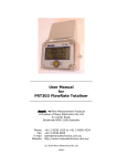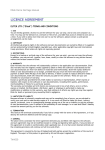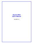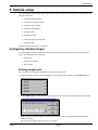
1
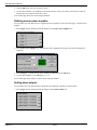
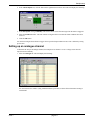
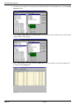
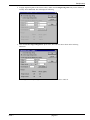
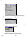
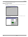
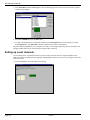
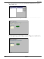
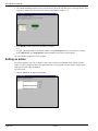
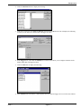
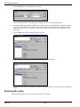
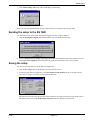
Sample setup
6 Sample setup
This section guides you through a sample logger setup in order to illustrate the procedure you would normally use.
The steps covered are:
• configuring standard ranges
• setting up an analogue channel
• setting up a pulse channel
• setting up event channels
• setting an action
• checking the setup
• sending the setup to the SQ 1600
• saving the setup.
To begin the setup, open Setwise for Windows.
Configuring standard ranges
You can configure a number of standard ranges and items that will be applied to channels during setup. In this
sample, the following will be configured:
• sample rates
• sensor power supplies
• alarm outputs.
Defining sample rates
You can define up to four different sampling rates. To define sample rates:
1. In the main Setwise window, click the Logger tab. This will display the following in the Sample rates area:
2. In the Sample rates area, click the button at the right-hand end of the A field. This will display the following:
3. In the seconds area (which currently shows 01) and use the up arrow (at the right-hand end of the field) to
change the setting
to 5. This sets the sample rate to once every five seconds.
issue 1
page 6-1
SQ 1600 User’s Manual
4. Click the OK button. The new rate will be shown.
5. Use the same technique to set the B rate to one minute and C to 100 ms (note that you will need to reduce the
seconds entry from 1 to 0 in each of these cases).
You can then apply these rates when setting up channels.
Defining sensor power supplies
You can define up to four different power supplies that can be applied to sensors from the logger. To define power
supplies:
1. In the Logger tab, the following should be displayed in the Sensor power supplies area:
2. In the Sensor power supplies area, click the button at the right-hand end of the A field. This will display the
following:
3. In the Voltage area (which currently shows 1.50) enter 2.25 and click the OK button.
4. Use the same technique to set the B supply to 1.75 V.
You can then apply these voltages to sensors when setting up channels.
Setting alarm outputs
You can define up to four different alarm outputs that can be applied to channels. To define alarms:
1. In the Logger tab, the following should be displayed in the Alarm outputs area:
page 6-2
issue 1
Sample setup
2. In the Alarm outputs area, click the button at the right-hand end of the A field. This will display the following:
3. In the Description field type Humidity. This will be shown as the alarm message when the alarm is triggered.
4. Select the Latched checkbox. This will continue to flag the alarm even when the alarm conditions have been
removed.
5. Click the OK button.
You can then configure these alarms to trigger when a specified input condition occurs. This is defined by setting
up an action.
Setting up an analogue channel
To illustrate the setup of an analogue channel, this sample will set channel 1 to use a voltage sensor that will
represent relative humidity.
1. Select the Analogue tab. This will display the following:
You can maximise this window (using standard Windows procedures) to show all the information relating to
each channel.
issue 1
page 6-3
SQ 1600 User’s Manual
2. The sensor type for channel 1 is currently shown as Not Set. Double-click this Not Set entry to open the Range
Selection window:
3. Select Voltage - Differential from the Sensor type list. The available ranges for this sensor type will be shown,
together with the wiring diagram:
4. Select -1.25 to 1.25 V as the range and click the OK button to close the window. Your selections should now
be reflected in the Analogue tab:
page 6-4
issue 1
Sample setup
5. To apply engineering units to the metered values, double-click the Engineering Units entry for the channel (it
currently shows Not Used). This will display the following:
6. Select the Use EU range settings below option button, then make the entries shown in the following
illustration:
This will generate an output range of 0 to 1 V which will be shown as 0 to 100% rh.
issue 1
page 6-5
SQ 1600 User’s Manual
7. To apply a sample rate, double-click the Log method column entry for the channel. This will display the
following:
8. From the Sample interval list, select Sample Rate B, a one minute rate that was set up when configuring
standard ranges.
9. Click the OK button. The new sample rate will be shown.
10. To select a power supply for the sensor, double-click the Not Used entry in the Sensor Power column for the
channel. This will display the following:
11. Select the B option button to apply a sensor supply of 1.75 V, then click the OK button. The new power supply
will be shown.
12. To set a stabilisation time that will be left after the input relay is turned on, click the Default entry in the Input
stabilisation column for the channel. This will display the following:
13. Change the indicated time to 100 ms then click the OK button.
14. To apply a meaningful name to the channel, double-click the Description entry for the channel (it currently
shows Channel 1). Type Humidity log, and this should be shown as the new description.
page 6-6
issue 1
Sample setup
The analogue channel configuration is now complete.
Setting up a pulse channel
Pulse channel setup is similar to the procedure above. This sample will configure a channel to measure pule rates
up to 32 kHz.
1. Select the Pulse tab. This will display the following:
2. The sensor type for channel 27 is currently shown as Not Set. Double-click this Not Set entry to open the
Range Selection window:
issue 1
page 6-7
SQ 1600 User’s Manual
3. Select Pulse Rate from the Sensor type list. The available ranges for this sensor type will be shown, together
with the wiring diagram:
4. Select 0 to 32000 Hz and click the OK button.
5. To apply a meaningful name to the channel, double-click the Description entry for the channel (it currently
shows Channel 27). Type Pulse Rate, and this should be shown as the new description.
The pulse channel configuration is now complete. Note that you could apply engineering units as described for the
analogue channel, but this was not done because the procedure is identical.
Setting up event channels
You can configure the event channel either to represent a single 256 state input or as eight independent event
inputs. This sample will adopt the latter approach, configuring four inputs to represent a fan, a hopper, a motor and
a side door sensor.
1. Select the Event tab. This will display the following:
page 6-8
issue 1
Sample setup
2. The sensor type for channel 29 is currently shown as Not Set. Double-click this Not Set entry to open the
Range Selection window:
3. Select State Event from the Sensor type list and click the OK button. This selection will be reflected in the
Event tab:
4. In the Description column of the State Settings area, enter Fan for Input 1 (double-click Input 1 and then
type Fan), Hopper for Input 2, Motor for Input 3 and Side door for Input 4. The tab should now look like
this:
issue 1
page 6-9
SQ 1600 User’s Manual
5. The 1 Text and 0 Text columns show the text that will be displayed when this input is in the high and low states
respectively. Make entries as shown in the following illustration for inputs 1 to 4:
6. In the Display column, deselect the checkboxes for inputs 5
to 8.
7. To apply a meaningful name to the channel, double-click the Description entry for the channel (it currently
shows Channel 29). Type Input monitor, and this should be shown as the new description.
The event channel configuration is now complete.
Setting an action
The actions capability of Setwise for Windows allows you to maximise the potential of the SQ 1600. For this
sample, we will set a high level alarm. You should note that you can program complex actions to trigger alarms
under only the exact required conditions.
To set the action:
1. click the Actions tab to display the following:
page 6-10
issue 1
Sample setup
2. Click the Add action button to display the following:
3. From the list of actions, select Turn on Alarm A (1) and click the OK button. This will display the following,
in which you can define the conditions that will trigger the action:
4. In the Triggers area, ensure that the Channel tab is selected. This allows you to configure conditions on the
channel inputs that will trigger the alarm.
5. Click the Add button to display the following:
6. Select Channel 1 A. Note that the A and B options allow two different triggers to be set for the same channel.
issue 1
page 6-11
SQ 1600 User’s Manual
7. Click the OK button. This will display the following:
As we calibrated channel 1 to measure relative humidity, this can be used to trigger the alarm.
8. Enter 65 in the Set field and 40 in the Reset field. Click the button at the right-hand side of the Set time field,
and set the time to 10 minutes (as described earlier in this sample) The alarm will then be triggered if relative
humidity rises above 65% for 10 minutes, and the alarm will be removed when the relative humidity drops to
below 40%.
9. Click the OK button. This will show the trigger conditions:
10. Click the Add selected trigger button to add the trigger to the action equation:
You will appreciate that you could build an expression combining a number of conditions that would trigger the
alarm.
Checking the setup
Before implementing the setup, you can check its consistency. To do this:
page 6-12
issue 1
Sample setup
1. Select Check settings (File menu). This should display the following:
2. Click the OK button to close the window.
If there are any errors indicated, these must be corrected before you send the setup to the SQ 1600.
Sending the setup to the SQ 1600
You can send the setup to the logger and begin the logging run using a single command:
1. Click the Start Squirrel logging button on the toolbar. This will display the following:
2. Click the Send the setwise settings to the logger then start a new run button. When the setup has been sent,
the message Start completed will be displayed in the status bar at the bottom of the Setwise window.
Saving the setup
You can save the setup both on your PC and in the logger itself:
1. Click the Save setup button on the toolbar to save the setup on your PC.
2. To store the setup in the SQ 1600 itself, select Store Squirrel setup (Squirrel menu). As the SQ 1600 can
store up to five setups, you will be presented with the following:
Note that as the setup saved by this operation is that currently in the logger itself, this will only be the same as
that on the Setwise screen if the Send setup to Squirrel function has already been performed.
issue 1
page 6-13
SQ 1600 User’s Manual
3. Select the Store 2 option button and click the OK button. On completion, the following will be displayed:
4. Click the OK button.
The logger is now running using your sample setup.
page 6-14
issue 1