1
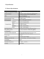
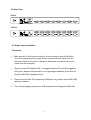
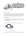
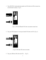
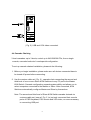
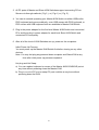
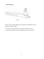
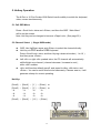
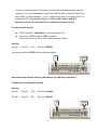
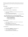
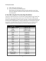
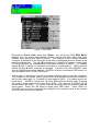
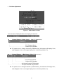
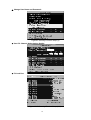
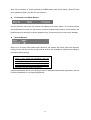
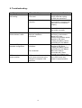
User Manual
Index
1. INTRODUCTION .............................................................................................................. 3
1.1 FEATURES .........................................................................................................................3
1.2 PACKAGE CONTENTS ..........................................................................................................3
2. SPECIFICATIONS ............................................................................................................ 4
2.1 GENERAL SPECIFICATION… ..… … … … … … … … … … … … … … … … … … … … … … … … ...4
3. SYSTEM REQUIREMENTS.............................................................................................. 5
4. INSTALLATION................................................................................................................. 5
4.1 FRONT VIEW ...................................................................................................................5
4.2 REAR VIEW ...................................................................................................................6
4.3 SINGLE STAGE INSTALLATION ...................................................................................6
4.4 CASCADE CHAINING....................................................................................................9
4.5 RACK MOUNTING.......................................................................................................12
5. HOTKEY OPERATION.....................................................................................................13
5.1 CALL OSD MENU .......................................................................................................13
5.2 CHANNEL SELECT......................................................................................................13
5.3 AUTO-SCAN FUNCTION .............................................................................................14
5.4 BUZZER SOUND DISABLE / ENABLE.......................................................................14
5.5 SETUP MODE..............................................................................................................15
5.6 CASCADE CHAIN LAYER CHANGE ..........................................................................15
5.7 HOT-KEY SELECT .......................................................................................................15
5.8 CONSOLE LOCK .........................................................................................................15
5.9 CONSOLE UNLOCK ....................................................................................................16
6. SUN MICRO SYSTEMS FUNCTION KEY EMULATION...................................................16
7. OSD OPERATION ...........................................................................................................17
7.1 OSD MAIN MENU .......................................................................................................17
7.2 FUNCTION CONTROL MENU.....................................................................................17
8. TROUBLESHOOTING .....................................................................................................22
2
1. Introduction
Thank you for purchasing our Combo KVM Switch! You now have a high
quality, durable system that will enable you to control 8 or 16 Host computers
and/or servers by using PS/2 and/or USB Connectors from one console (PS/2
& USB Mouse, PS/2 & USB Keyboard, and one Monitor).
1.1 Features
1. Console your Keyboard/Mouse via either way of PS/2 and/or USB arbitrarily.
2.
3.
Complex connections with PCs via either way of PS/2 and/or USB arbitrarily.
Controls 8 or16 computers from a single console (Keyboard/Mouse) over PS/2
and/or USB connections.
4. Supports Windows, Linux, Mac OS9/OSX, Sun Microsystems.
5. On-Screen-Display (OSD) & Cascade Chain functions.
- OSD is intuitive menus driven for quick and efficient navigation.
- 3 level cascades: up to 3 levels; control up to 64/256/4096 PCs, from a single
console; cascaded units don’
t need special configuration.
6. Emulates PS/2 or USB keyboard on each PC to allow your computers to boot
normally without a keyboard error.
7. Supports hot-pluggable. All devices connected to the KVM can be added or
removed at any time, without shutting the unit down.
8. Supports 3 types of switching:
(1) Hardware Push Button, (2) Hot-Keys on PS/2 and/or USB of keyboard,
(3) Menu driven OSD ( On Screen Display).
9. Supports Auto-Scan function to switch video automatically among computers in
preset intervals sequentially by OSD menu driven.
10. Supports LED display for PC and/or server status monitoring.
11. Supports VGA resolutions up to 2048 x 1536 @ 85HZ.
12. Supports Beeper during Switching enabled.
13. Powered with external power adaptor connection.
14. Fully compliant with the USB 1.1/ 2.0 specification.
15. Rack Mountable in 19”system tack ( 1U ).
1.2 Package Contents
The product you purchased should contain the following equipment and
accessories:
1 8-Port or 16-Port Combo KVM Switch .
1
User Manual.
1
Power adaptor
1
Rack Mount Kit
3
2. Specifications
2.1 General Specifications
Specification
Number Of Computers Controlled
8 or 16
Selection Method
Push Button, Hot-Key (PS/2 and/or USB Keyboard)
or On-Screen-Display (OSD) & Cascade Chain
LEDs
Red for PC Selection
Green for PC On-Line ready
Video
( PS/2 & USB signal combined )
PC Connectors
Console Ports
1 x HDB-15 male
Keyboard
1 x 6 pin mini-DIN female
Mouse
1 x 6 pin mini-DIN female
Video
1 x HDB-15 female
Keyboard
1 x USB – A type female
Mouse
1 x USB – A type female
Auto-Scan Interval
Adjustable time setting by OSD menu driven
DDC, DDC2 monitor
Yes ( Max. Resolution: 2048x1536 )@85Hz
Hot Swappable
Yes
Operating systems supported
Windows 98SE/ME/2000/XP/2003 Server, Linux
Mac OS9/OSX and Sun Micro Systems
Device driver
No Need
Power
By external power adaptor
Dimensions (L X W X H)
44 x 15.7 x 4.5 cm (17.3 x 6.1 x 1.5 inch )
Unit Weight
1900 g
Housing material
Metal
Operating Temperature
32~ 122°F (0~ 50°C )
Humidity
0%~80%RH
4
3. System Requirements
Console
A VGA, SVGA, Multisync monitor capable of the highest resolution.
PS/2 and/or USB Keyboard/Mouse
Computer or Server
The following equipment must be equipped with each computer or server.
- VGA, SVGA or Multisync card.
- Type A USB port or PS/2 6 pin mini-DIN for Keyboard and Mouse.
Cables
The Combo KVM Switch must be used specific custom 3-in-1 cables.
To purchase the specific cable sets, please contact your dealer.
4. Installation
4.1 Front View
8-Port
16-Port
LED Indicators:
Selected : RED LED indicates that the KVM Switch is selected to the corresponding PC.
On-Line : GREEN LED indicates that the KVM Switch is ready to the corresponding PC.
Reset Switch :
Press this switch for a system reset. This switch must be pushed with a thin object,
for example, such as the end of a paper clip, or a ball point pen.
5
4.2 Rear View
8-Port
16-Port
4.3 Single stage installation
Precaution:
1.
Make sure all of devices are turning off as connecting up with KVM Switch.
You must unplug the power cords of any computers which might have the
Keyboard Power On function in advance. Otherwise, the switch will receive
power from the computer.
2.
Running under OS Windows 98 , we suggest that the PC must be plugged to
PS/2 ports, because Windows 98 is not supporting installation at first time as
through USB H2D installation driver.
3.
There are some older PCs supporting USB ports only, please open BIOS USB
setting in advance.
4.
The console plugging supports no USB keyboard with integrated USB HUB.
6
( Fig. 1 )
Console connecting:
Plug either your USB keyboard, mouse or PS/2 keyboard, mouse arbitrarily and
VGA video into the Console ports located on the KVM Switch’
s rear panel. ( Fig.1)
( Note: No matter what you plugged even thought USB mouse with PS/2 keyboard
or PS/2 mouse with USB keyboard are working with the KVM Switch unit.)
System connecting:
Use KVM custom cable sets to connect any available PC ports to the video and
either USB or PS/2 ports, or even USB & PS/2 all connected of the computers
you are connecting up.
To purchase the custom KVM cable sets, please contact with your dealer.
( Fig 2 ) custom combo 3-in-1 cable
This KVM Switch with custom specific cable set provide three connectiing methods.
7
1. Plug USB, PS/2 ( keyboard/mouse) ports and VGA video into PCs at same time,
recommended in priority. ( Fig. 3 )
( Fig. 3 ) PS/2 & USB and VGA video connected at same time.
2. Plug only PS/2 (keyboard / mouse) ports and VGA video into PCs ( Fig. 4 ).
( Fig. 4 ) PS/2 and VGA video connected.
3. Plug only USB and VGA video into PCs.
8
( Fig. 5 ).
( Fig. 5 ) USB and VGA video connected.
4.4 Cascade Chaining
3 level cascades: up to 3 levels; control up to 64/256/4096 PCs, from a single
console; cascaded units don’
t need special configuration.
To set up cascade chained installation, please do the following:
1. Before you begin installation, please make sure all devices connected have to
be turned off power before connecting.
2. Use the custom cable set ( Fig. 2 ), cascade chain connecting the second and
third level of one or more Slave KVM Switches to any PC port to the Master
KVM Switch. Cascade configuration expands system ability and allows you to
select computers connected to the Master or Slave. After connected, KVM
Switches automatically configure Master and Slave by themselves.
Note: The second and third level of Slave KVM Switch cascade chained via
custome cable set ( see ref. Fig. 2 ) is just only connected their console
ports of PS/2 Keyboard, PS/2 mouse and VGA video, no more necessary
to connecting USB port.
9
3. All PC ports of Master and Slave KVM Switches support connecting PCs or
Servers via through methods ( Fig 3 ), or ( Fig.4 ) or ( Fig. 5 ).
4. You can do console operating your Master KVM Switch via either USB and/or
PS/2 keyboard and mouse arbitrarily, even USB mouse with PS/2 keyboard, or
PS/2 mouse with USB keyboard both are available to Master KVM Switch.
5. Plug in the power adapter for the first level Master KVM Switch and connected
PCs, and then plug in power adapter for each level Slave KVM Switch and
connected PCs sequently.
6. After all of the level of KVM Switches are up, power on the computers.
Initial Power-Up Process:
You must power up the Master KVM Switch first before turning on any other
devices.
Note: You may hot plug any powered-down computer and Slave KVM at any
time after initial power up process completed.
Hot plug and Hot Swap:
a) You can replace keyboard or mouse of the Master KVM CONSOLE port at
any time without powering down the Master KVM.
b) Plug in or out of PC port or swap PC port could be at any time without
powering down the KVM.
10
( Fig. 6 )
11
4.5 Rack Mounting
( Fig.7 )
Figure 7 shows you how to attach mounting brackets to the KVM Switch unit for
standard 19-inch rack cabinet.
1. Screw the mounting brackets into the sides of the KVM Switch unit.
2. Slide the KVM Switch unit into the rack cabinet and secure it to the rack.
12
5. Hotkey Operation
The 8-Port or 16-Port Combo KVM Switch has the ability to switch the keyboard,
video, mouse simultaneously
5.1 Call OSD Menu
Press < Scroll lock> twice and <Enter>, and then the OSD “Main Menu”
will be on the screen.
Note: Hot-Key can be changed to become <Caps Lock>. (See page 20 )
5.2 Channel Select
( Single KVM mode )
l
OSD: Use Up/Down arrow and <Enter> to select the channel directly.
l
Hot-Key via PS/2 and/or USB Keyboard
Press <Scroll Lock> twice, and then Keying a channel number ( 1 to 16 )
And then press <Enter>.
Left <Alt> or right <Alt> pushed twice, the PC channel will automatically
l
l
shift left/right one channel ( channel decrease / increase to next ),
while <Alt> enables.
<Alt> shift function default was off, and press Hot-Key <Alt> twice, and
<Enter>. You can be on/off this function alternately. If buzzer was on, it will
generate a beep for correct operating.
Hot Key:
[Scroll] → [Scroll] → [ 1 ] → [Enter] or
[Scroll] → [Scroll] → [ 2 ] → [Enter] or
-à
-à
-à
[Scroll] →
-à
-à
-à
[Scroll] →
-à
-à
-à
-à
-à
-à
[ 16 ] → [Enter]
13
You can synchronize the PC selection, by using the following two-step Hot Key
sequence. To send commands to the Combo KVM Switch, press the [Scroll] key
twice (Step 1), then press key ( 1 to 16 ) and [Enter] (step 2) to assign the PC to
a particular PC. (If you press key [ 1 to 16 ] on the number pad, the
keyboard, mouse & video will also be switched synchronously.)
5.3 Auto-Scan Function
l
OSD: Call OSD “Main Menu”, and then press <F2>.
l
Hot-Key via PS/2 and/or USB Keyboard
Press <Scroll Lock> twice, <S> and then press <Enter>.
Hot Key:
[Scroll] → [Scroll] → [S] → [Enter] to BEGIN.
Any key pushed will STOP the Auto-Scan operation.
Auto-Scan time interval setting is adjustable via OSD menu operation.
5.4 Buzzer sound Disable / Enable
Hot Key:
[Scroll] → [Scroll] → [B] → [Enter] to Disable
[Scroll] → [Scroll] → [B] → [Enter] to Enable
.
14
The Buzzer sound default setting is “Enable”. While the switching connections are
activated and Buzzer sound is in “Enable”status, the beeper has a short beeping
sound.
5.5 Setup Mode
l
l
OSD: Call OSD “Main Menu”, and then press <F1>.
No Hot-Key operating.
5.6 Cascade Chain Layer Select
(Channel Select )
l
OSD: Call OSD “Main Menu”, select channel and then press <Enter>
layer by layer.
l
Hot-Key via PS/2 and/or USB Keyboard
Press <Scroll Lock> twice, <D>, number (1,2,3… … 16), and Press <Enter>.
Note: With cascading 3 layers, you can select last layer directly;
Example : press <Scroll Lock> twice, then D2D5D7, and <Enter>:
D2 : layer 1 channel 2 links to
D5 : layer 2 channel 5 links to
D7 : layer 3 channel 7 selected
5.7 Hot-Key Select
l
OSD: Call OSD “Main Menu”, and then press <F1>, and then select
Hot-Key change.
l
Hot-Key via PS/2 and/or USB Keyboard
Press current Hot-Key twice, <K> and then press <Enter>.
The Hot-Key will change to another one.( <Scroll Lock> or <Caps Lock>).
5.8 Console Lock
l
OSD: Call OSD “Main Menu”, and then press <F3>
( <F5>: Security mode must be turn on first.)
l
Hot-Key via PS/2 and/or USB Keyboard
Press <Scroll Lock> twice, <H>, and Press <Enter>.
15
5.9 Console unlock
l
l
OSD: Display the message only.
Hot-Key via PS/2 and/or USB Keyboard
Press any key into the Unlock window, and then enter the correct User
Name and Password. KVM and console device will unlock and be back to
normal operation.
6. Sun Micro System Function Key Emulation:
There are 16 special functions on the Sun Micro system keyboard, the Combo Free
KVM Switch can emulate these function keys via the PS/2 and/or USB keyboard.
Here is the mapping table for these functions operation. To active these emulation on
the PS/2 and/or USB keyboard, you have to press the LEFT Window KEY first (this
key usually is located between the left [Ctrl] and left [Alt]), do not release the lift
Window key choice the second relative key, and then release the two keys.
Sun Micro System
Function Key
Stop
PS/2 Keyboard
Props
L_Win & L_Ctrl
Compose
L_Win & L_Shift
Front
L_Win & F1
Open
L_Win & F2
Find
L_Win & F3
Again
L_Win & F4
Undo
L_Win & F5
Copy
L_Win & F6
Paste
L_Win & F7
Cut
L_Win & F8
Help
L_Win & F11
Power
L_Win & F12
Mute
L_Win & 1
Volume Down
L_Win & 2
Volume UP
L_Win & 3
L_Win & L_Alt
16
7. OSD Operation
OSD (On-Screen-Display) Operation
l
OSD Main Menu for Administrator
1
2
3
4
5
6
Figure 8: Administrator OSD
7.1 OSD Main Menu
1. KVM layer number: 1st, 2nd, 3rd
2. PC name (defined by user): 31 characters (Max.)
3. PC Status: (Status: STA, See sabove figure 8)
s
X Buzzer sound on
Buzzer sound off
L Locked port indication, and normal is blank
¿ Indicating the computer is powered on
s Indicating the channel scan function is on
4. Current channel number
5. Cascade channel number: only display cascade 2nd,
connected channel number; if it’
s in 1st layer, it will show blank.
3rd
layer
6. Page down-up indicator: (to next page) while connecting 16 port OSD KVM, it
will show up & down arrows alternatively to select previous/next page’
s port
number. (Only for 16-port KVM only.)
7.2 Function Control Menu
F1:
F2:
F3:
F4:
F5:
F6:
Set up: basic set up menu
Scan: autoscan function
Lock: setup lock/unlock, and available when F5 Security is set ‘
ON’
Rename: rename selected port name.
Security: security function and user priority setting
Lock Port: PC port lock function (administrator only)
17
●
OSD Main Menu for Other User (1, 2, 3)
Figure 9 : User OSD
By pressing <Scroll Lock> twice and <Enter>, you will see an OSD 'Main Menu'
popped up in the screen with channel number, names and other status and other
function keys, please see figure 8 above. The channel of the currently selected
computer is displayed in the top right corner and a highlighted pink bar shown in the
selected channel row. The sign ¿ is displayed if computer has power on and ready
for being selected (its corresponding front panel indicator is green). If it doesn’
t
appear ¿ sign, it means no computer connected or no powered up. OSD menu will
update the sign ¿ when computer is activated. Use the <UP> and <DOWN> arrow
keys to highlight a computer and the <ENTER> to select it and leave OSD menu. Or,
you can press <ESC> to exit OSD menu.
A plus mark (+) showing in the left of a name indicates that the port has cascades.
The number at the up-left corner (below KVM layer number) shows the number of
port for the upper layer, i.e. 8 means link from upper KVM 8. If in master layer it will
show blank. <ENTER> brings you one level down and the screen pops up listing
the names of the computers on the Slave KVM. The name of the Slave will be
shown at the OSD menu. It is useful to group computers and still be able to see the
group name. Press <R> will return to upper layer OSD menu. Press <ESC> to
exit OSD and to return to the selected computer; the computer name is also shown
on the screen with a left-up banner.
18
● F1: Setup Mode
Figure 10:
OSD Setup
All changes are enabled by left/right arrow key (← →) to select it.
■Scan Mode: Select – Scan selected channels in ‘
STA’column with ‘
s’on OSD
main menu.
PC ON – Scan all powered-on PC channels only.
■Scan Time: 5 sec(Default) to 90 sec., 5 sec. a select step
■Banner Display Time: 5 sec. (Default), 10 sec., 15 sec, and always on (∞).
■Display Position: Menu – use four arrow keys to move the OSD main menu to the
desired position.
Banner – use four arrow keys to move the channel banner to the
desired position.
■Hot-Key: Scroll Lock – Scroll Lock becomes the Hot-Key.
Caps Lock – Caps Lock becomes the Hot-Key.
Ctrl – Ctrl is a defaulted Hot-Key.
Note: Scroll and Caps Lock are alternative. While Scroll Lock is enabled, if you want
to alter the Hot-Key to Caps Lock, you just press ‘
Scroll Lock’twice, K, and <enter>,
and vice versa.
■Sound: ON – Buzzer sound enabled. (Turn on)
OFF – Buzzer sound disabled. (Turn off)
■Language: English (En) / Deutsch (De) / Francais (Fr), 3 languages.
19
Position Adjustment
●
Figure 11: Select Items to Setup
Into the banner Display Position, the display will become:
l
Channel Banner ( Single Layer )
┬
(Max. 22 characters)
────┬──────
│
└PC (Channel) Name
└───────────── Channel (PC) Number
n PC powers on or change channel by OSD/Hot-Key, this banner will display 5 sec,
and disappear. User can change display time in the Setup Mode (F1).
l
Channel Banner
( Multi-Layer ) (Max. 22 characters)
┬
┬
┬
────┬──────
│
│
│
│
│
└─────── Channel (PC) Number
│
└─────── 2nd Layer Channel (PC) Number
└ PC (Channel) Name
└───────────1st Layer Channel (PC) Number
n PC powers on or changes channel by OSD/Hot-Key, this banner will display 5sec.,
and disappear. User can change display time in the Setup Mode (F1).
20
Channel Banner (Scan Mode)
l
─┬──
│
│
┬
──┬──────
│
└─PC (Channel) Name
└──────── Channel (PC) Number
└───────────── Scan Mode
n Stop scan: press any key.
n Banner will disappear when the scan stops.
l
F4: Rename (New Name: 31 characters Max)
Figure 12: F4 Function Setup
21
l
F5: Security Mode
Entry Password:
(Default User Name: admin, Password: 123456)
After entering correct password, Security function is enabled.
Figure 13: Security Function Setup (1)
After the Security mode is ‘
ON’status, and F3 Lock Mode will be enabled automatically (it
will display on the Main Menu).
Also the Hot-Key Lock function (H) will be available.
After security mode is on, you can actively lock Hot-Key function (F3 or <H> Hot-Key), until
keyin a password, the console will be locked as log-out status. (Hot-Key twice, <H>, and
<Enter>) Only administrator can keyin password to unlock the console, but according to the
limit of authority setting, different user will have different access computers.
●
Change Administrator Password:
Figure14: Security Function Setup (2)
22
● Change User Name and Password:
Figure15: Security Function Setup (3)
● User PC Channel Authorization Setting
● F6 Lock Port
Figure16-17: Security Function Setup (4-5)
23
After PC port locked, “L”mark will show in its STA column until unlock status. (Select F6 and
keyin password again, and the PC port unlocks.)
l
F3 Console Lock Mode Banner:
Into the Security lock mode, this banner will display until Unlock status. The console device
and KVM button will lock (no any function could be enabled while back to unlock status); the
keyboard will just accept the correct password only. (Press any key into the unlock window.)
l
Unlock Window:
After key in a correct User Name and Password, the system will unlock (leave the Security
mode), screen will be into the normal and all devices are available to operate (according to
the authorization setting).
Note: If you forget the password, the only
way to permanently disable the security
function is to key in a universal password to
unlock KVM. You need to key in this unlock
password to release your device and KVM,
and then you can restart everything.
Universal password will let your KVM go back to defaulted administrator password, ask the
Universal password to your agency/distributor.
24
8. Troubleshooting :
Symptom
Keyboard and/or Mouse
not working.
Possible Cause
Keyboard and/or Mouse need
to be reset
Failed connection to the
computer.
Recommended Solution
To unplug from console
port(s), and then replug
it / them into console in.
Check the cable connected
from switch to computer and
make sure it is connected
properly.
KVM Switch needs to be reset
Power off all of devices and
then power up again.
Master/ Slave daisy
chained doesn’
t work
Incorrect configuration or
improper installation
procedures
Double OSD images at
cascade configuration
Improper slave connection
procedure.
Make sure the console of
the Slave’
s connected to
Master’
s PC port.
Remove any possible power
supplies to the slave
( unplug all cables), before
connecting it to the Master.
Remove any possible power
supplies to the Slave
( unplug all cables), before
connecting it to the Master.
Make sure cable is
connected well, Slave
console link to Master port.
Use <F1>: Set/Position to
move OSD menu and
banner to proper position.
Fail connection
OSD menu is not at the
proper position
OSD menu has fixed resolution
and its size varies due to the
changes of computer VGA
resolution
25
FCC Statement
This device generates and uses radio frequency and may cause interference to radio and television reception if not installed
and used properly. This has been tested and found to comply with the limits of a Class B computing device in accordance with
the specifications in Part 15 of the FCC Rules. These specifications are designed to provide reasonable protection against such
interference in a residential installation. However, there is no guarantee that interference will not occur in a particular installation.
If this device does cause harmful interference to radio or television reception, which can be determined by plugging the device
in and out, the user can try to correct the interference by one or more of the following measures:
l
Reorient or relocate the receiving antenna.
l
Increase the separation between the device and receiver.
l
Connect the computer into an outlet on a circuit different from that to which the receiver is connected.
l
Consult the dealer or an experienced radio/TV technician for help.
Safety Information:
This device may only be operated in enclosed, dry rooms. To prevent the risk of fire or electrical shock, the device must be
protected from moisture. In the event of a defective power plug, please contact an authorized retailer. In the event of damage to
the housing or the power plug, do not operate. Do not open the device. Repairs may only be performed by an authorized
retailer.
Note:
In the event of incorrect installation and improper use in a residential area, the device may cause disruptions in radio devices
and other electronic devices. Proper use means that the device is operated with shielded connector cables as far as possible,
for network products also with shielded cables of category 5e and higher. The device was tested and lies within the limits for
computer accessories of class A according to the requirements of EN 55022.
Warning:
This is a class A device. This device can cause radio interference in residential areas; in this case, the operator may be
required to perform and bear the costs for appropriate measures.
Conformity Declaration:
The device fulfils the EMC requirements of EN 55022 class A for ITE and EN 55024. Devices with external or built-in power
supply also fulfil the requirements of EN 61000-3-2 and EN 61000-3-3. The basic protection requirements of the “EMC
Directive”89/336/EEC are therefore fulfilled. The CE conformity has been certified. The corresponding declarations are
available from the manufacturer.
Trademarks:
All company, brand and product names used in these instructions are trademarks or registered marks of the corresponding
companies.
26