1
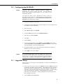
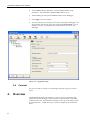
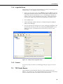
User Manual 7.2.4 LoggerNet Setup The next step is to run LoggerNet and configure it to connect to the datalogger via the Ethernet port. (See example in Figure 7-2 below.) In the LoggerNet Setup screen, press Add Root and choose IPPort. Input the datalogger’s IP address and port number. The IP address and port number are input on the same line separated by a colon. (The datalogger’s default port number is 6785. It can be changed using DevConfig. Unless firewall issues exist, the port number does not need to be changed from its default value.) Add a PakBus® Port. Add the datalogger (CR800, CR1000, or CR3000) and input the PakBus® address of the datalogger. You can verify that your settings are correct by selecting the datalogger in the Network Map, selecting the Clock tab, and pressing Check Clocks. If your settings are correct, you should see the current clock of your server and datalogger. Figure 7-2. Bridge mode LoggerNet setup 7.2.5 Connect You are now ready to connect to your datalogger using the LoggerNet Connect screen. 7.3 TCP Serial Server The NL200/201 can tunnel RS-232 and CS I/O serial communications over Ethernet. Any packet sent to the configured Ethernet IP port will have the IP layer removed, and the serial data is then directed to the serial connection. 15