1
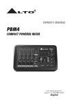
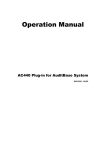
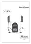
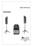
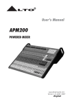
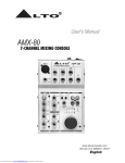
R
LTO
User's Manual
PBM4 SISTEMA
PORTABLE PA SYSTEM
www.altoproaudio.com
Version 2.0 SEP. 2007
English
IMPORTANT SAFETY INSTRUCTION
CAUTION
RISK OF ELECTRIC SHOCK
DO NOT OPEN
TO REDUCE THE RISK OF ELECTRIC SHOCK
PLEASE DO NOT REMOVE THE COVER OR
THE BACK PANEL OF THIS EQUIPMENT.
THERE ARE NO PARTS NEEDED BY USER
INSIDE THE EQUIPMENT. FOR SERVICE,
PLEASE CONTACT QUALIFIED SERVICE
CENTERS.
WARNING
To reduce the risk of electric shock
and fire, do not expose this equipment
to moisture or rain.
Dispose of this product should
not be placed in municipal waste
and should be separate collection.
11. Move this Equipment only with a cart,
stand, tripod, or bracket,
This symbol, wherever used, alerts you to the
specified by the
presence of un-insulated and dangerous voltages
manufacturer, or
within the product enclosure. These are voltages that
sold with the
may be sufficient to constitute the risk of electric
Equipment. When
shock or death.
a cart is used, use
This symbol, wherever used, alerts you to
caution when
important operating and maintenance instructions.
moving the cart /
Please read.
equipment
Protective Ground Terminal
combination to
AC mains (Alternating Current)
avoid possible
Hazardous Live Terminal
injury from tip-over.
ON: Denotes the product is turned on.
12. Permanent hearing loss may be caused by
OFF: Denotes the product is turned off.
exposure to \ extremely high noise levels.
CAUTION
The US. Government's Occupational Safety
Describes precautions that should be observed to
and Health Administration (OSHA) has
prevent damage to the product.
specified the permissible exposure to noise
1. Read this Manual carefully before operation.
level.
2. Keep this Manual in a safe place.
These are shown in the following chart:
3. Be aware of all warnings reported
with this symbol.
HOURS X DAY SPL EXAMPLE
4. Keep this Equipment away from water and
90 Small gig
8
moisture.
92 train
6
5. Clean it only with dry cloth. Do not use
95 Subway train
4
solvent or other chemicals.
97 High level desktop monitors
3
6. Do not damp or cover any cooling opening.
100 Classic music concert
2
Install the equipment only in accordance with
102
1,5
the Manufacturer's instructions.
105
1
7. Power Cords are designed for your safety. Do
110
0,5
not remove Ground connections! If the plug
0,25 or less 115 Rock concert
does not fit your AC outlet, seek advice from
a qualified electrician. Protect the power
According to OSHA, an exposure to high SPL in
cord and plug from any physical stress to
excess of these limits may result in the loss of
avoid risk of electric shock. Do not place
heat. To avoid the potential damage of heat, it is
heavy objects on the power cord. This could
cause electric shock or fire.
recommended that Personnel exposed to
equipment capable of generating high SPL use
8. Unplug this equipment when unused for long
hearing protection while such equipment is
periods of time or during a storm.
under operation.
9. Refer all service to qualified service personnel
The apparatus shall be connected to a mains
only. Do not perform any servicing other than
those instructions contained within the
socket outlet with a protective earthing
User's Manual.
connection.
10. To prevent fire and damage to the product,
use only the recommended fuse type as
indicated in this manual. Do not short-circuit
the fuse holder. Before replacing the fuse,
make sure that the product is OFF and
disconnected from the AC outlet.
The mains plug or an appliance coupler is used
as the disconnect device, the disconnect device
shall remain readily operable.
IN THIS MANUAL:
1.
2.
3.
4.
5.
6.
7.
8.
INTRODUCTION................................................................................1
FEATURES.......................................................................................1
QUICK START..................................................................................4
CONTROL ELEMENTS......................................................................5
INSTALLATION & CONNECTION........................................................8
BLOCK DIAGRAM..........................................................................10
TECHNICAL SPECIFICATIONS...........................................................11
WARRANTY..................................................................................12
1. INTRODUCTION
Thank you for purchasing the amazing portable PA system PBM4 SISTEMA.
This system is small enough to fit into any airplane's overhead storage
compartment yet being flexible and powerful enough to be used for small gigs
and professional multimedia presentations. PBM4 SISTEMA includes a 45+45
watt stereo amplifier, a 5-channel mixer, and 2x5" full range speakers. The chassis
is made by moulded polypropylene for shock and moisture protection.
Your PBM4 SISTEMA is the ideal tool for: Multimedia Presentations, Weddings,
Small Church Functions, Gym, Music Rehearsal, Small Gigs, School Functions,
and more .
Enjoy your PBM4 SISTEMA and make sure to read this Manual carefully before
operation!
2. FEATURES
Compact moulded polypropylene case
Modern design & Lightweight
2x5" full range speakers
3-band equalizer on input channels
5 Input channels with individual Volume control and 2 bands EQ
3 bands Master EQ
3 XLR microphone Inputs with phantom power(+15V)
2 RCA Line Inputs
2 RCA Line Outputs
Monitor/Headphone output
Monitor/Headphone level control
2 powered output (45+45 watt) for optional external speakers
1
HIGH
12KHz
0
0 +15dB
HIGH
12KHz
-15dB
LOW
80Hz
-15dB
0
R
0 +15dB
0
HIGH
+15dB
MIDDLE
-15dB
0
+10dB
LINE IN (bal.)
LEVEL
RE
A
+15dB -
0 +15dB
0
+15dB
BASS
-15dB
0
+15dB
0
HIGH
12KHz
-15dB
LOW
80Hz
-15dB
1
LOW NOISE P
2
3
M
M
M
P
P
P
CH 3
MIC IN (bal.)
0
0 +15dB
10
0
-10
-30
0
OPERATING
OFF
PHANTOM
ON
MONITOR OUT
MAIN POWER OUT
+10dB
MONITOR
-
0
+10dB
IN
OUT
TAPE
LEVEL
CH 4
+15dB -
8
MAIN
0
dB
+10dB
LEVEL
80Hz
LOW
-15dB
12KHz
HIGH
-
8
-15dB
8
0
-15dB
+10dB
LINE IN (bal.)
LEVEL
RE
A
+15dB -
1
LOW NOISE P
2
3
8
CH 2
MIC IN (bal.)
8
LTO
0
LINE IN (bal.)
LEVEL
RE
A
+15dB +10dB
PBM4 SISTEMA
-15dB
LOW
80Hz
-15dB
1
LOW NOISE P
2
3
8
CH 1
MIC IN (bal.)
2
HT
IG
OT
L
SP
3. QUICK START
This is the fastest way to get something out from your PBM4 SISTEMA, if you have
a keyboard and a microphone.
a. Well, there is not really much to say before starting to operate the PBM4 SISTEMA.
It includes Mixer, Amplifiers and Speakers, so just put it on a clean table first and
make sure that the Power switch on the back panel is on OFF position.
b. Turn down the Input Channel Gain Controls and the MAIN and MONITOR controls.
c. Keep Input Channel EQ and Master EQ controls in center position.
d. Only at this point you can connect the AC cable into an AC socket and you can
switch the system ON.
e. Now connect a microphone into Channel 1-3 or a Line Instrument into Channel 4.
f. Slowly turn up the Input Channel LEVEL Control and then the MAIN Control.
g. For an optimal sound reproduction make sure that the -10 and 0 LEDs on the
Master LED Meter are blinking.
Here you are. It is your first gig with your PBM4 SISTEMA..
3
HOOK
MULTIMEDIA PRESENTATION
UP
MAIN
R
LTO
BASS
MIDDLE
HIGH
0
0
0
MONITOR
OPERATING
10
0
dB
0
0
-10
PBM4 SISTEMA
PHANTOM
-30
ON
+15dB
-15dB
-
-
+10dB
OFF
+10dB
8
+15dB
-15dB
8
+15dB
-15dB
LEVEL
0
0
HIGH
12KHz
12KHz
0 +15dB
-15dB
LOW NOISE P
8
+10dB
LEVEL
LOW NOISE P
RE
A
+10dB
LOW NOISE P
RE
A
+15dB -
-15dB
MAIN POWER OUT
+10dB
LEVEL
RE
A
M
2
1
3
LINE IN (bal.)
MONITOR OUT
IN
P
P
1
3
+10dB
LEVEL
M
2
LINE IN (bal.)
0
80Hz
+15dB -
-15dB
LEVEL
P
1
3
0 +15dB
-15dB
LOW
80Hz
+15dB -
-15dB
M
2
12KHz
0
LOW
80Hz
+15dB -
-15dB
0 +15dB
-15dB
0
LOW
80Hz
HIGH
12KHz
0 +15dB
-15dB
0
LOW
0
HIGH
8
0
HIGH
8
MIC1
8
MIC2
TAPE
LINE IN (bal.)
OUT
MIC IN (bal.)
MIC IN (bal.)
CH 1
MIC IN (bal.)
CH 2
CH 3
CH 4
Headphone
Laptop Computer
Wireless MIC System
Tape Recorder
iPOD ,CD Player. MP3
This will be typical setting for a Business Presentation making use of PowerPoint slides
and background music/effects generated by CD player, iPOD or other sources such as
Mp3 Players. The Presenter has up to 2 microphones available and a wireless microphone
can also be connected for the use of the audience. The entire presentation can be
recorder via Tape or DAT Recorder.
HOOK
SMALL GIG WITH EXTERNAL SPEAKERS
UP
Passive Speakers
MAIN
R
LTO
BASS
MIDDLE
HIGH
0
0
0
MONITOR
0
0
-10
PBM4 SISTEMA
PHANTOM
-30
ON
+15dB
-15dB
+15dB
-15dB
+15dB
-
-
+10dB
OFF
+10dB
8
-15dB
8
MIC
OPERATING
10
0
dB
LEVEL
0
12KHz
0 +15dB
-15dB
0
-15dB
0
80Hz
LOW NOISE P
+10dB
+15dB -
-15dB
LEVEL
LOW NOISE P
RE
A
LEVEL
12KHz
0 +15dB
0
MAIN POWER OUT
80Hz
LOW NOISE P
+10dB
LEVEL
-15dB
+15dB -
+10dB
LEVEL
RE
A
M
IN
P
1
3
0 +15dB
LOW
+15dB -
-15dB
P
2
LINE IN (bal.)
-15dB
0
M
P
1
3
+10dB
RE
A
M
2
8
LOW
80Hz
8
LOW
80Hz
+15dB -
HIGH
12KHz
0 +15dB
LOW
-15dB
0
HIGH
8
12KHz
-15dB
0
HIGH
8
0
HIGH
2
LINE IN (bal.)
1
3
MONITOR OUT
TAPE
LINE IN (bal.)
OUT
MIC IN (bal.)
CH 1
MIC IN (bal.)
CH 2
MIC IN (bal.)
CH 3
CH 4
Powered Stage Monitor
DAT Recorder
Guitar
Keyboard
Drum Machine
In this case up to three Musicians (Vocalist, Guitar Player and Keyboard Player) can
hookup to the PBM4 SISTEMA and an additional Drum Machine can also be connected
to the Stereo Channel. Two external passive speakers can be connected (the internal
speakers will be automatically be disconnected) as well as a powered stage Monitor.
4
OT
L
IG
4.
3. CONTROL ELEMENTS
HT
1 THE MONO INPUT CHANNELS
0
HIGH
12KHz
-15dB
0 +15dB
6
0
LOW
5
80Hz
+15dB -
-15dB
LOW NOISE P
+10dB
LEVEL
RE
A
M
P
These are marked CH1 to CH3 and include a
balanced XLR socket (MIC IN) and a balanced
1/4" socket (LINE IN). Use the XLR socket to
connect a low impedance balanced dynamic
microphone or a low level signal. You can also
connect a Condenser microphone into the XLR
socket (See following about Phantom Power).
Use the LINE IN socket to connect a Line Level
Instrument such as a keyboard or a drum machine.
You can also connect an electric guitar or bass
through an option DI Box (Direct Injection Box)
8
SP
2
1
3
LINE IN (bal.)
1
MIC IN (bal.)
2 PHANTOM POWER SWITCH
CH 1
When the (2) switch is at ON position, a +15V
phantom power will be applied to CH1 through
CH3. Only Condenser microphones need Phantom
Power, so switch it OFF when you use dynamic
microphones.
PHANTOM
3 TAPE IN
Here you can connect a stereo Line Level via RCA
sockets. Usually this stereo channel will be used to
connect into the PBM4 SISTEMA with the audio output
of a Computer, or a CD Player, iPOD, MP3 player, etc.
4 TAPE OUT
2
ON
OFF
LEVEL
Via these two RCA sockets you can route out the
Main Stereo signal usually to a Tape Recorder or
DAT Recorder.
IN
3
TAPE
OUT
4
CH 4
5 LEVEL CONTROL
It adjusts the LEVEL of individual channels with a range from
to +10dB.
6 CHANNEL EQ
Each Input channel has its own 2 bands equalizer with an adjustable range of
+/-15 dB. The HIGH control creates a shelving filter that will boost/cut all
frequencies above 12 kHz. You can use it to eliminate high frequency noise and
hiss (such as those produced by Tape Recorders) or to boost and make crispier
the cymbals or certain harmonics of the human voice. The LOW control will
create a shelving filter that will boost/cut frequencies below 80 Hz. Use the
LOW control to put in evidence Kick Drum or enhance male voice.
5
SP
OT
L
IG
4.
3. CONTROL ELEMENTS
HT
THREE BANDS MASTER EQ
This equalization circuit is inserted before the MAIN level control. You have available
3 controls: BASS, MIDDLE and HIGH.
7 HIGH
Use it as a further boost to the overall MIX
to get more colour from your program or
turn the control down if you want to avoid
high frequency noise.
9
8
7
8 MIDDLE
This is a unique control designed for a wide variation of middle frequencies. Turn
the control down (from center position) and you will make the human voice more
warm and smooth while turning the control up will enhance vocal intelligibility. Be
careful not to boost these frequencies too much to avoid feedback on microphone
inputs.
9 LOW
Turn the control down (from center position) if you experience rumble or low
frequency noise or turn it up to make the PBM4 SISTEMA sound much bigger
than what it is.
10 MONITOR OUT
Connect a powered Monitor to this socket or
an external Amplifier + Monitor Speaker. You
can also use it to connect a pair of Headphones.
11 MAIN POWER OUT
You can connect a pair of passive speakers to
these Output sockets. In this case, the internal
speakers will be disconnected and the 45W x 2
internal amplifier signal will be assigned to these
sockets.
11
MAIN POWER OUT
MONITOR OUT
10
6
SP
OT
L
IG
4. CONTROL
CONTROL ELEMENTS
ELEMENTS
3.
HT
12 MAIN
There is the Main Mix Control adjusting the overall volume assigned to the 2
internal speakers or to the MAIN POWER OUT speakers.
13 MAIN LED METER
This 4 segments LED Meter will monitor the volume assigned by the MAIN level
control. If the +10 LED flashes, you have reached the limit of the internal
45+45W amplifier and the outgoing signal is approaching distortion. +10 LED
should flash only occasionally. If no LED is blinking, it means that the output
level is too low, so either you do not hear any music or the signal is too low to
the noise level. For optimal functioning LEDs marked -10 and 0 should always
be blinking.
14 MONITOR
Via this Control, you can adjust the signal
Level applied to the MONITOR OUT sockets.
15 OPERATING
This LED will blink when your PBM4 SISTEMA
is switched ON.
REAR PANEL
12
13
14
15
2
16 POWER ON/OFF
This switch is used to turn the main power ON/OFF.
17 AC INLET
Use it to connect your PBM4 to the main AC with the supplied AC cord. Please
check the voltage available in your country and how the voltage for your PBM4
SISTEMA is configured before attempting to connect your PBM4 SISTEMA to
the main AC.
POWER
ON
OFF
16
FUSE 2A
AC~230V
50/60Hz
17
7
5. INSTALLATION AND CONNECTION
Ok, you have got to this point and you are now in the position to successfully operate
your PBM4 SISTEMA. However, we advise you to read carefully the following section to
be the real master of your own mix. Not paying enough attention to the input signal
level, to the routing of the signal and the assignment of the signal will result in
unwanted distortion, a corrupted signal or no sound at all. So you should follow this
procedure for every single channel:
1. Turn down all Input and output gain controls.
2. Connect phantom powered microphones before switching on the +15Volt phantom
power switch.
3. Set the output level of your PBM4 SISTEMA or the connected power amplifier at
no more than 75%.
4. Now, set the MONITOR level at no more than 50%. In this way you will be able to
hear later what you are doing connecting a pair of headphones or a pair of powered
studio monitor speakers.
5. Position EQ controls on middle position.
6. Increase the input gain properly for maintaining the good headroom and ideal dynamic
range.
7. Depending on the actual application, turn slowly the input and output level controls
for obtaining the maximum gain before distortion.
8. Now repeat the same sequence for all input channels. The main LED meter could
move up into the red section. In this case you can adjust the overall output level
through the MAIN MIX control.
Audio Connections
You can connect unbalanced equipment to balanced inputs and outputs. Simply follow
these schematics.
Sleeve
Tip
Ring
Ring=Right Signal
Strain Clamp
Tip=Left Signal
Sleeve=Ground/Screen
Use for Headphone
1/4" Stereo (TRS) Jack Plug
Sleeve
Tip
Tip=Signal
Strain Clamp
Sleeve=Ground/Screen
Use for Mono Line In, Mono 1/4"Jack Plugs
1/4" Mono (TS) Jack Plug
8
5.
AND CONNECTION
3. INSTALLATION
CONTROL ELEMENTS
Sleeve
Ring=Return Signal
Tip
Ring
Strain Clamp
Tip=Send Signal
Sleeve=Ground/Screen
Use for Insert Points
1/4" Stereo (TRS) Jack Plug
2=Hot(+)
2
3
1
1=Ground/Screen
2
2=Hot(+)
3
1
1=Ground/Screen
3=Cold(-)
3=Cold(-)
Use for Balanced Mic Inputs
(For unbalanced use, connect pin 1 to 3)
Use for Main output
(For unbalanced use, leave pin3 unconnected)
3-pin XLR Male Plug
3-pin XLR Line Socket
(seen from soldering side)
(seen from soldering side)
MAIN SPEAKERS CONNECTION
Please use only the power connectors to make connections with other signal
source equipment for the passive speaker cabinets. The power connector has
four terminals: 1+, 1-, 2+, 2-.
1-
2-
1+
2+
Speakon connector
9
A
B
C
1
2
3
1
CH INPUT
(CH1-3)
[-30/-10dB]
HI-Z
[-40/-20dB]
LOW-Z
PHANTOM
+15V
ON
OFF
2
[10dB]
HI
2-STAGE EQ
LOW
3
HA
3
[0dB]
LEVEL
[-10dB]
4
4
MAIN BUS
MAIN BUS
5
5
6
3-BAND EQ
MONITORLEVEL
LOW
D
2
MID
MAIN-BUS
MAIN BUS
10
6
HI
1
2TK IN
LEVEL
MAIN LEVEL
( 4 POINT )
8
7
R
T
S
S
2
R
T
S
MONITOR OUT
8
TAPE OUT
OUTPUT
1
2-TRACK
TAPE IN
POWER AMPLIFIER
ALTO PBM4 SISTEMA
7
A
B
C
D
6. BLOCK DIAGRAM
6.
7. TECHNICAL
TECHNICALSPECIFICATIONS
SPECIFICATION
Input channels
Microphone Input
Frequency response
Distortion(THD&N)
Gain
SNR(Signal to Noise Ratio)
Line input
Frequency response
Distortion(THD&N)
Gain
Impedances
Microphone Input
Channel Insert return
All other inputs
Tape out
All other outputs
Equalization
Hi shelving
Low shelving
Main Mix Section
Noise(Bus noise)
Monitor max out
Amplifier Section
Output Power
Frequency Response
Output Impedance
Power supply
Main voltage
Power Consumption
Fuse
Physical
Dimension
Net Weight
Gross
Weight
Noise
(Bus
noise)
Electronically balanced, discrete input configuration
10 Hz to 55 kHz, +/- 3 dB
0.05% at +4 dBu, 1 kHz
30 dB
>94 dB
Electronically balanced
10 Hz to 55 kHz, +/- 3 dB
0.05% at +4 dBu, 1 kHz
10 dB
1.4 kOhm
2.5 kOhm
10 kOhm or greater
1 kOhm
120 Ohm
+/-15 dB@12 kHz
+/-15 dB@80 Hz
Fader 0 dB, channels muted: -85 dBr (ref.: +4 dBu)
Fader 0 dB, all input channels assigned and set to
UNITY gain: -81 dBr(ref.: +4 dBu)
+22 dBu unbalanced, 1/4"jacks
45W x 2 RMS (Nominal power)
25 Hz-20 kHz
8 ohm
66W x 2(EIAJ)
USA/Canada
100 120V~, 60 Hz
Europe
210 240V~, 50 Hz
U.K./Australia
240V~, 50Hz
133 watts
100-120V~: T4A
21 0-240V~: T2A
318x194x160 mm(LxWxH)(12.5"x7.6"x6.3")
6.23 Kg
8.0 KgFader 0 dB, channels muted: 85dBr (ref.:+4dBu)
11
8. WARRANTY
1. WARRANTY REGISTRATION CARD
To obtain Warranty Service, the buyer should first fill out and return the enclosed
Warranty Registration Card within 10 days of the Purchase Date.
All the information presented in this Warranty Registration Card gives the
manufacturer a better understanding of the sales status, so as to provide a
more effective and efficient after-sales warranty service. Please fill out all the
information carefully and genuinely, miswriting or absence of this card will void
your warranty service.
2. RETURN NOTICE
2.1 In case of return for any warranty service, please make sure that the
product is well packed in its original shipping carton, and it can protect your
unit from any other extra damage.
2.2 Please provide a copy of your sales receipt or other proof of purchase with
the returned machine, and give detail information about your return address
and contact telephone number.
2.3 A brief description of the defect will be appreciated.
2.4 Please prepay all the costs involved in the return shipping, handling and
insurance.
3. TERMS AND CONDITIONS
3.1 LTO warrants that this product will be free from any defects in materials
and/or workmanship for a period of 1 year from the purchase date if you
have completed the Warranty Registration Card in time.
3.2 The warranty service is only available to the original consumer, who purchased
this product directly from the retail dealer, and it can not be transferred.
3.3 During the warranty service, LTO may repair or replace this product at its
own option at no charge to you for parts or for labor in accordance with the
right side of this limited warranty.
3.4 This warranty does not apply to the damages to this product that occurred
as the following conditions:
Instead of operating in accordance with the user's manual thoroughly, any abuse
or misuse of this product.
Normal tear and wear.
The product has been altered or modified in any way.
Damage which may have been caused either directly or indirectly by another
product / force / etc.
Abnormal service or repairing by anyone other than the qualified personnel or
technician.
And in such cases, all the expenses will be charged to the buyer.
3.5 In no event shall LTO be liable for any incidental or consequential damages.
Some states do not allow the exclusion or limitation of incidental or
consequential damages, so the above exclusion or limitation may not apply to
you.
3.6 This warranty gives you the specific rights, and these rights are compatible
with the state laws, you may also have other statutory rights that may vary
from state to state.
12
SEIKAKU TECHNICAL GROUP LIMITED
NO. 1, Lane 17, Sec. 2, Han Shi West Road, Taichung 40151, Taiwan
http://www.altoproaudio.com Tel: 886-4-22313737
email: [email protected] Fax: 886-4-22346757
All rights reserved to ALTO. All features and content might be changed
without prior notice. Any photocopy, translation, or reproduction of part of this
manual without written permission is forbidden. Copyright c 2007 Seikaku Group
NF02337-1.1