1
MSL-3S79
3-Slot Gigabit Modular L2 Managed Switch
User Manual
V1.0
I
FCC Warning
This Equipment has been tested and found to comply with the limits for a Class-A
digital device, pursuant to Part 15 of the FCC rules. These limits are designed to
provide reasonable protection against harmful interference in a residential installation.
This equipment generates uses and can radiate radio frequency energy and, if not
installed and used in accordance with the instructions, may cause harmful interference
to radio communications. However, there is no guarantee that interference will not
occur in a particular installation. If this equipment does cause harmful interference to
radio or television reception, which can be determined by turning the equipment off
and on, the user is encouraged to try to correct the interference by one or more of the
following measures:
Reorient or relocate the receiving antenna.
Increase the separation between the equipment and receiver.
Connect the equipment into an outlet on a circuit different from that to which the
receiver is connected.
Consult the dealer or an experienced radio/TV technician for help.
CE Mark Warning
This is a Class-A product. In a domestic environment this product may cause radio
interference in which case the user may be required to take adequate measures.
II
Content
0 hapter 1 Introduction ............................................................................................... 1
BC
8B1.1 Hardware Features ................................................................................................. 2
9B1.2 Software Feature .................................................................................................... 4
10B1.3 Package Contents .................................................................................................. 6
1BChapter 2 Hardware Description ...................................................................................... 8
1B2.1 Physical Dimension ................................................................................................ 8
12B2.2 LED Indicators ........................................................................................................ 8
13B2.3 Rear Panel ............................................................................................................ 10
2BChapter 3 Hardware Installation ..................................................................................... 11
14B3.1 Desktop Installation .............................................................................................. 11
15B3.2 Rack-mounted Installation .................................................................................... 11
16B3.3 Power On .............................................................................................................. 12
3BChapter 4 Network Application....................................................................................... 13
17B4.1 Desktop Application .............................................................................................. 13
18B4.2 Segment Application ............................................................................................. 13
4BChapter 5 Console Management .................................................................................... 15
19B5.1 Connecting to the Console Port ............................................................................ 15
20B5.2 Login in the Console Interface .............................................................................. 15
21B5.3 CLI Management .................................................................................................. 16
5BChapter 6 Web-Based Management ............................................................................... 17
2B6.1 About Web-based Management ........................................................................... 17
23B6.2 Preparing for Web Management ........................................................................... 17
24B6.3 System Login ........................................................................................................ 18
25B6.4 System .................................................................................................................. 18
51B6.4.1 System Information ..................................................................................... 18
52B6.4.2 Switch Information ...................................................................................... 19
75B6.4.2.1 Main Board ....................................................................................... 19
76B6.4.2.2 Management Software ..................................................................... 19
53B6.4.3 IP Configuration .......................................................................................... 20
54B6.4.4 DHCP Configuration ................................................................................... 20
5B6.4.5 Firmware Update ........................................................................................ 22
7B6.4.5.1 TFTP Download Firmware ................................................................ 22
78B6.4.5.2 TFTP Backup Configuration ............................................................. 22
III
79B6.4.5.3 TFTP Restore Configuration ............................................................. 23
56B6.4.6 System Event Log ...................................................................................... 23
80B6.4.6.1 LOG Configuration............................................................................ 23
81B6.4.6.2 Logging Events Level ....................................................................... 25
82B6.4.6.3 Logging RAM Table .......................................................................... 26
83B6.4.6.4 Logging Flash Table ......................................................................... 27
57B6.4.7 Security Manager ....................................................................................... 27
26B6.5 Port ....................................................................................................................... 28
58B6.5.1 Port Statistics.............................................................................................. 28
59B6.5.2 Port Information .......................................................................................... 28
60B6.5.3 Port Control ................................................................................................ 29
61B6.5.4 Port Trunk ................................................................................................... 30
84B6.5.4.1 Trunk Configuration .......................................................................... 30
85B6.5.4.2 Trunk Information ............................................................................. 31
86B6.5.4.3 Port Activity ...................................................................................... 31
62B6.5.5 Port Mirror................................................................................................... 32
63B6.5.6 Rate Limiting............................................................................................... 34
27B6.6 Protocol ................................................................................................................ 34
64B6.6.1 VLAN .......................................................................................................... 34
87B6.6.1.1 VLAN Mode Configuration ................................................................ 35
8B6.6.1.2 Port VLAN Id Configuration .............................................................. 35
89B6.6.1.3 VLAN Entry ....................................................................................... 36
65B6.6.2 Rapid Spanning Tree .................................................................................. 37
90B6.6.2.1 STP System Configuration ............................................................... 37
91B6.6.2.2 STP Port Configuration..................................................................... 39
6B6.6.3 SNMP ......................................................................................................... 40
67B6.6.4 QoS ............................................................................................................ 41
92B6.6.4.1 QoS Configuration ............................................................................ 42
93B6.6.4.2 Port-bace Configuration.................................................................... 42
94B6.6.4.3 COS Configuration ........................................................................... 43
95B6.6.4.4 DSCP Configuration ......................................................................... 43
68B6.6.5 SNTP .......................................................................................................... 44
69B6.6.6 IGMP .......................................................................................................... 45
96B6.6.6.1 IGMP Configuration .......................................................................... 45
IV
97B6.6.6.2 IGMP Static Configuration ................................................................ 46
70B6.6.7 LLDP........................................................................................................... 47
98B6.6.7.1 LLDP Configuration .......................................................................... 47
9B6.6.7.2 LLDP Neighbor Table ....................................................................... 48
28B6.7 Security ................................................................................................................. 48
71B6.7.1 802.1x/ RADIAS ......................................................................................... 48
10B6.7.1.1Misc Configuration ............................................................................. 48
10B6.7.1.2 Port Configuration............................................................................. 50
102B6.7.1.3Radius Client Configuration ............................................................... 50
72B6.7.2 Port Security ............................................................................................... 51
103B6.7.2.1 Static MAC Address Table ............................................................... 51
104B6.7.2.2 Filter MAC Address Table ................................................................ 52
105B6.7.2.3 MAC Address Table Aging ............................................................... 53
73B6.7.3 IP Security .................................................................................................. 53
74B6.7.4 ACL ............................................................................................................ 54
29B6.8 Factory Default ..................................................................................................... 55
30B6.9 Save Configuration ............................................................................................... 55
31B6.10 System Reboot ................................................................................................... 56
6BTroubleshooting .............................................................................................................. 57
7BAppendix A- Command Sets ........................................................................................... 59
32BCommands Set List .................................................................................................... 59
3BSystem Commands Set .............................................................................................. 60
34BPort Commands Set ................................................................................................... 61
35BMac / Filter Table Commands Set .............................................................................. 63
36BPort Mirroring Commands Set .................................................................................... 65
37BTFTP Commands Set ................................................................................................. 65
38BQOS Commands Set .................................................................................................. 66
39BSpanning Tree Commands Set .................................................................................. 67
40BVLAN Commands Set................................................................................................. 69
41BSystem log Commands Set ........................................................................................ 71
42BSNTP Commands Set ................................................................................................ 73
43BIGMP Commands Set ................................................................................................. 74
4BTRUNK Commands Set.............................................................................................. 75
45BSNMP Commands Set................................................................................................ 76
V
46BDHCP Server Commands Set .................................................................................... 77
47BSecurity IP Commands Set......................................................................................... 78
48B802.1X Commands Set............................................................................................... 78
49BLLDP Commands Set ................................................................................................. 79
50BACL Commands Set ................................................................................................... 80
VI
Chapter 1 Introduction
0B
The MSL-3S79 is a modular switch that can be used to build high-performance
switched workgroup networks. This switch is a store-and-forward device that offers low
latency for high-speed networking. The Switch is targeted at workgroup, department or
backbone computing environment.
The MSL-3S79 features a “store-and-forward” switching scheme. This allows the
switch to auto-learn and store source address in an 16K-entry MAC address table.
MDI (Medium Dependent Interface) Port is also called an "uplink port". The MDI port
does not cross transmit and receive lines, which is done by the regular ports (MDI-X
ports) that connect to end stations. In general, MDI means connecting to another Hub
or Switch while MDIX means connecting to a workstation or PC. Therefore, Auto
MDI/MDIX means that you can connect to another Switch or workstation without
changing non-crossover or crossover cabling.
The MSL-3S79 has 3-module slot. User can purchase the modules in accordance with
their needs as well as giving elasticity on network application.
1
1.1 Hardware Features
8B
IEEE 802.3 10BASE-T
IEEE 802.3u 100BASE-TX
IEEE 802.3z Gigabit fiber
IEEE 802.3ab 1000Base-T
IEEE 802.3x Flow control and Back pressure
Standards
IEEE 802.3ad Port trunk with LACP
IEEE 802.1d Spanning tree protocol
IEEE 802.1w Rapid spanning tree
IEEE 802.1p Class of service
IEEE 802.1q VLAN Tagging
IEEE 802.1x User authentication
IEEE 802.1ab LLDP
System Power
10/100/1000TX module: Link/Activity, 1000/100/10Mbps
speed
LED Indicators
8 Port Gigabit Fiber module: Link/Activity
8 Port MINI GBIC: Link/Activity
4 Port Gigabit copper + 4 Port MINI GBIC module: RJ-45
(Link/Activity, 1000/100/10Mbps speed), MINI GBIC
(Link/Activity)
RS-232 console: Female DB-9
Gigabit copper module: 8 x RJ-45
Connector
MINI GBIC module: 8 x MINI GBIC socket
Gigabit Fiber module: 8 x SC for Gigabit SX or LX
4 Gigabit Copper & 4 MINI GBIC module: 4 x RJ-45 + 4 x
3.3v MINI GBIC Socket
Switch architecture
Store and forward switch architecture with Back-plane up to
2
48Gbps.
Packet buffer
6Mbits
Dimensions
440mm(W) x 280mm(D) x 44mm(H)
MAC Address
16K
Storage Temp.
-40℃~70℃, 5%~95%RH
Operational Temp.
0℃~45℃, 5%~95%RH
Power Supply
Power
Consumption
AC 100~240V 50/60Hz,
Redundant Power: DC 12~48V
35 Watts
Ventilation
2 fan at the rear
EMI
Compliance with FCC Class A, CE
Safety
Compliance with UL, cUL, CE/EN60950-1
3
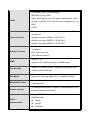
1.2 Software Feature
9B
Management
SNMP v1/v2c, Telnet, RMON1, CLI and Web management.
RFC 2863 Interface Group MIB,
RFC 1213 MIBII,
RFC 1493 Bridge MIB,
MIB
RFC 2674 VLAN MIB,
RFC 1643 Ethernet Like MIB,
RFC 1215 Trap MIB,
RFC 1757 RMON MIB,
Private MIB
Cold start/Warm start trap,
SNMP Trap
Link down/Link up trap,
Authentication fail trap,
Firmware Upgrade
TFTP
Configuration
upload and
System quick installation and backup by TFTP
download
Support IEEE802.3ad with LACP function.
Port Trunk
Up to 7 trunk groups with failover feature and the member
up to 8 ports.
Spanning Tree
IEEE802.1w Rapid spanning tree (Compatible with STP)
4
Port based VLAN, up to 24 groups
IEEE802.1Q Tag VLAN
VLAN
Static VLAN groups up to 256 entries and dynamic VLAN
groups up to 2048, the VLAN ID can be assigned from 1 to
4094.
GVRP
Per port 8 priority queues and support strict and WRR
priority rule.
Class of Service
Weight round ratio (WRR):1:2:3:4:5:6:7:8
Weight round ratio (WRR):1:1:2:2:3:3:4:4
Weight round ratio (WRR):1:1:2:2:4:4:8:8
Port based,
Quality of service
Tag based,
IPv4 Type of service,
IPv4 Different service.
IGMP
Port Security
Port Mirror
Bandwidth Control
Access security
IGMP v1, v2
Supports 256 multicast groups and IGMP query
Support 128 entries of MAC address for static MAC and
another 128 for MAC filter
Supports 3 mirroring types: “RX, TX and Both packet”.
Per port support ingress rate limiting and egress rate
shaping control.
IP Management Security: Support IP addresses security to
prevent unauthorized intruder.
Support IEEE802.1x User-Authentication and can report to
802.1x
Authentication
RADIUS server.
Reject
Accept
Authorize
5
Access Control List
DHCP
DNS
Disable
The system provides control list on Source IP & Destination
IP.
DHCP Client and DHCP Server
Provide DNS client feature and support Primary and
Secondary DNS server.
1000 records (Maximum)
System log
Provide remote storage ability and also can view the log by
Web/Telnet/SNMP interface.
SNTP
Support RFC 2030 SNTP client.
System supports 5 mail accounts and 2 Mail servers for
Primary and Secondary.
SMTP
The SMTP will auto send event message to supervisor
whom is pre-defined in the SMTP system through the
pre-defined mail server.
Packet filter
Broadcast storm control
LLDP
Support IEEE 802.1ab Link Layer Discovery Protocol
1.3 Package Contents
10B
Unpack the contents of the MSL-3S79 and verify them against the checklist
below.
One MSL-3S79
Four Rubber Feet
6
Power Cord
Rack-mounted kit
RS-232 Cable
CD Manual
Compare the contents of your MSL-3S79 package with the standard checklist above.
IF any item is missing or damaged, please contact your local dealer for service.
7
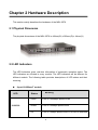
Chapter 2 Hardware Description
1B
This section mainly describes the hardware of the MSL-3S79.
2.1 Physical Dimension
1B
The physical dimensions of the MSL-3S79 is 440mm(W) x 280mm(D) x 44mm(H)
2.2 LED Indicators
12B
The LED Indicators gives real-time information of systematic operation status. The
LED indicators are located in every module. The LED indicators will be different for
different module. The following table provides descriptions of LED status and their
meaning.
8-port 1000Base-T module
LED
106B
1000/100
Status
Meaning
107B
Green
Link on 1000Mbps speed mode
Amber
Link on 100Mbps speed mode
Off
Link on 10Mbps speed mode or No device attached
8
LK/ACT
Green
Ethernet Link connected
Blink
The port is receiving or transmitting data.
Off
No device attached or Link is disconnected
4-port 1000Base-T + 4-port Mini GBIC module
LED
108B
Status
Meaning
109B
Gigabit Copper
1000/100
LK/ACT
Green
Link on 1000Mbps mode
Amber
Link on 100Mbps speed mode
Off
Link on 10Mbps speed mode or No device attached
Green
Ethernet Link is connected
Blink
The port is receiving or transmitting data.
Off
No device attached or Link is disconnected
Mini GBIC
LK/ACT
Green
Link is connected
Blink
The port is receiving or transmitting data.
Off
No device attached or Link is disconnected
9
8-port Mini GBIC module
LED
Meaning
Status
12B
LNK/ACT
Green
Link connected
Blink
The port is receiving or transmitting data.
Off
No device attached or Link is disconnected
2.3 Rear Panel
13B
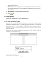
The 3-pronged power plug is located at the Rear Panel of the MSL-3S79 as shown in
figure. The Switches will work with AC in the range 100-240V AC, 50-60Hz. The DC
redundant power jack is optional.
Rear Panel of the MSL-3S79
10
Chapter 3 Hardware Installation
2B
3.1 Desktop Installation
14B
Set the switch on a sufficiently large flat space with a power outlet nearby. The surface
where you put your Switch should be clean, smooth, level, and sturdy. Make sure
there is enough clearance around the Switch to allow attachment of cables, power
cord and air circulation.
Attaching Rubber Feet
1.
Make sure mounting surface on the bottom of the Switch is grease and dust free.
2.
Remove adhesive backing from your Rubber Feet.
3.
Apply the Rubber Feet to each corner on the bottom of the Switch. These
footpads can prevent the Switch from shock/vibration.
3.2 Rack-mounted Installation
15B
The switch come with a rack-mounted kid and can be mounted in an EIA standard size,
19-inch Rack. The Switch can be placed in a wiring closet with other equipment.
Perform the following steps to rack mount the switch:
A.
Position one bracket to align with the holes on one side of the switch and secure it
with the smaller bracket screws. Then attach the remaining bracket to the other
side of the Switch.
B.
After attaching both mounting brackets, position the switch in the rack by lining up
the holes in the brackets with the appropriate holes on the rack. Secure the
Switch to the rack with a screwdriver and the rack-mounting screws.
Note: For proper ventilation, allow about at least 4 inches (10 cm) of clearance on
the front and 3.4 inches (8 cm) on the back of the Switch. This is especially
important for enclosed rack installation.
11
3.3 Power On
16B
Connect the power cord to the power socket at the rear panel of the Switch. The other
side of power cord connects to the power outlet. The internal power can work with AC
in the voltage range of 100-240VAC/ frequency 50~60Hz or 12-48VDC (It’s optional).
Besides, The AC and DC input can be used for redundant power supply. When one
fails, another one is able to keep providing power to the switch. Check the power
indicator on the front panel to see if power is properly supplied.
12
Chapter 4 Network Application
3B
This section provides you a few samples of network topology in which the switch is
used. In general, the MSL-3S79 is designed as a segment switch. That is, with its
large address table (16K MAC address) and high performance, it is ideal for
interconnecting networking segments.
PC, workstations, and servers can communicate each other by directly connecting
with MSL-3S79. The switch automatically learns nodes address, which are
subsequently used to filter and forward all traffic based on the destination address.
.
By using Gigabit or Gigabit Fiber, the switch can connect with another switch or hub to
interconnect other small-switched workgroups to form a larger switched network.
Meanwhile, you can also use Ethernet or Gigabit fiber ports to connect switches.
4.1 Desktop Application
17B
The MSL-3S79 is designed to be a switch that is an ideal solution for small
workgroup. The Switch can be used as a standalone switch to which personal
computers, server, printer server are directly connected to form small
workgroup.
4.2 Segment Application
18B
For enterprise networks where large data broadcast are constantly processed, this
switch is suitable for department user to connect to the corporate backbone.
You can use the MSL-3S79 to connect PCs, workstations, and servers to each other.
All the devices in this network can communicate with each other by connecting directly
to the Switch. Connecting servers to the backbone switch allow other users to access
the server’s data.
13
The switch automatically learns node address, which are subsequently used to filter
and forward all traffic based on the destination address. You can use any of the RJ-45
port of the MSL-3S79 to connect with another Switch or Hub to interconnect each of
your small-switched workgroups to form a larger switched network.
14
Chapter 5 Console Management
4B
5.1 Connecting to the Console Port
19B
The Console port is a female DB-9 connector that enables a connection to a PC or
terminal for monitoring and configuring the Switch. Use the supplied RS-232 cable
with a male DB-9 connector to connect a terminal or PC to the Console port.
Connecting the switch to a terminal via RS-232 cable
5.2 Login in the Console Interface
20B
When the connection between Switch and PC is ready, turn on the PC and run a
terminal emulation program or Hyper Terminal and configure its communication
parameters to match the following default characteristics of the console port:
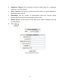
Baud Rate: 9600 bps
Data Bits: 8
Parity: none
Stop Bit: 1
Flow control: None
15
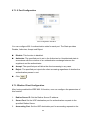
The settings of communication parameters
After finishing the parameter settings, click “OK“. When the blank screen shows up,
press Enter key to get into command line mode. Please see below figure for login
screen.
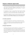
5.3 CLI Management
21B
The system supports console management (CLI command). After you login to the
system, you will see a command prompt. To enter CLI management interface, enter
“enable” or “e” command.
CLI command interface
16
Chapter 6 Web-Based Management
5B
This section introduces the configuration and functions of the Web-Based
management.
6.1 About Web-based Management
2B
On CPU board of the switch there is an embedded HTML web site residing in flash
memory, which offers advanced management features and allow users to manage the
switch from anywhere on the network through a standard browser such as Microsoft
Internet Explorer.
The Web-Based Management supports Internet Explorer 5.0 or later. And, it is applied
for Java Applets for reducing network bandwidth consumption, enhance access speed
and present an easy viewing screen.
[NOTE] By default, IE5.0 or later version does not allow Java Applets to activate
sockets. In fact, the user has to explicitly modify the browser setting to enable Java
Applets to operate network ports.
6.2 Preparing for Web Management
23B
Before using web management, install the industrial switch on the network and make
sure that any one of PC on the network can connect with the industrial switch through
the web browser. The switch default value of IP, subnet mask, username and
password is as below:
IP Address: 192.168.1.1
Subnet Mask: 255.255.255.0
Default Gateway: 192.168.1.254
User Name: admin
Password: admin
17
6.3 System Login
24B
1.
Launch the Internet Explorer on the PC
2.
Key in “http:// “+” the IP address of the switch”, and then Press “Enter”.
3.
The login screen will appear right after
4.
Key in the user name and password. The default user name and password are
the same as “admin”
5.
Press “Enter” or ”OK”, and then the home screen of the Web-based management
appears
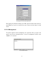
6.4 System
25B
6.4.1 System Information
51B
Assigning the system name, location and view the system information
System Name: Assign the name of switch. The maximum length is 31 bytes
Description: Display the description of switch. The maximum length is 31 bytes
Location: Assign the switch physical location. The maximum length is 31 bytes
Contact: Enter the name of contact person or organization
Object ID: object ID. The most common OIDs seen "in the wild" usually belong to
the private enterprise numbers allocated by IANA under the 1.3.6.1.4.1
(iso.org.dod.internet.private.enterprise) arc. In computer networking, an OID, in
the context of the Simple Network Management Protocol (SNMP), consists of the
object identifier for an object in a Management Information Base (MIB).
18
System information interface
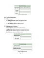
6.4.2 Switch Information
52B
6.4.2.1 Main Board
75B
Hardware Version: display the hardware version
Fan 1 Status: display the status of Fan 1
Fan 2 Status: display the status of Fan 2
6.4.2.2 Management Software
76B
Firmware Version: display the firmware version
Configure Data version: display the configure data version
Command Line Version: display the command line version
Web UI Version: display the Web UI version
Switch information interface
19
6.4.3 IP Configuration
53B
User can configure the IP Settings.
IP Address Mode:
Static: It means the IP address of this switch will be assigned by user.
DHCP: It means the IP address of this switch will be assigned by the network
DHCP server.
IP Address: Assign the IP address that the network is using. If IP Address Mode
function is set in DHCP mode, user needn’t assign the IP address manually. And,
the network DHCP server will assign the IP address which is going to be
displayed in this column for the switch. The default IP is 192.168.1.1
Subnet Mask: Assign the subnet mask of the IP address. If IP Address Mode
function is in DHCP mode, user need not assign the subnet mask manually.
Gateway IP Address: Assign the network gateway for the switch. The default
gateway is 192.168.1.254
DNS1: Assign the IP address of DNS server1 that the network is using.
DNS2: Assign the IP address of DNS server2 that the network is using.
MAC Address: Display the unique hardware address assigned by manufacturer
(default)
And then, click Apply
IP configuration interface
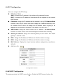
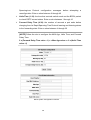
6.4.4 DHCP Configuration
54B
The system provides the DHCP server function. Enable the DHCP server function, the
20
switch system will be a DHCP server.
DHCP Server Settings
1.
DHCP Server: Enable or disable the DHCP Server function. Enable – the switch
will be a DHCP server on your local network.
2.
DHCP IP Address Pool: User has to set a range of IP addresses for the DHCP
server assigning an IP address to the DHCP client by giving the starting IP
address and how many IP addresses within this address pool. For instance, user
can set 192.168.1.100 to be the beginning IP address and 50 (can’t be greater
than 253) to be the maximum number. The range of the address pool should be
from 192.168.1.100 to 192.168.1.49.
3.
Netmask: the dynamic IP assign range subnet mask.
4.
Default Gateway: the gateway in your network.
5.
DNS Servers: Domain Name Server IP Address in your network.
6.
Lease Duration(hours): Assign the lease duration time in hours
7.
And then, click Apply
21
DHCP Server Configuration interface
DHCP Client Information
Display the DHCP Client information which has gotten an IP address from the DHCP
server.
6.4.5 Firmware Update
5B
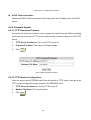
6.4.5.1 TFTP Download Firmware
7B
It provides the functions to allow a user to update the switch firmware. Before updating,
make sure you have your TFTP server ready and the firmware image is on the TFTP
server.
1.
TFTP Server IP Address: Fill in your TFTP server IP.
2.
Firmware File Name: The name of firmware image.
3.
Click Apply .
TFTP-Update Firmware interface
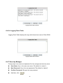
6.4.5.2 TFTP Backup Configuration
78B
User can save current EEPROM value from the switch to TFTP server, then go to the
TFTP restore configuration page to restore the EEPROM value.
1.
TFTP Server IP Address: Fill in the TFTP server IP
2.
Backup File Name: Fill in the file name
3.
Click Apply .
22
TFTP-Configuration Backup interface
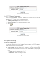
6.4.5.3 TFTP Restore Configuration
79B
User can restore EEPROM value from TFTP server, but user must put back the
backup file in TFTP server, switch will download it back.
1.
TFTP Server IP Address: Fill in the TFTP server IP.
2.
Restore File Name: Fill in the correct restore file name.
3.
Click Apply .
TFTP-Configuration Restore interface
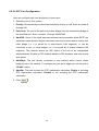
6.4.6 System Event Log
56B
6.4.6.1 LOG Configuration
80B
You can mark the check box of Local Logging, Remote Logging, and SMTP Logging to
enable the functions of LOG Configuration.
Local Logging: Mark this check box for enabling to set Flash Level and RAM
Level. Set Flash Level to send event log to flash ROM or RAM by assigning the
level.
Flash Level: Set the level range of 0 to 7.
RAM Level: Set the level range of 0 to 7.
23
Remote Logging: Mark this check box for enabling to set Facility Level, Trap
Level, Log Server IP 1, and Log Server IP 2.
Facility Level: Set the level range of 16 to 23.
Trap Level: Set the level range of 0 to 7.
Log Server IP 1: Assign a remote log server IP address.
Log Server IP 2: Assign a remote log server IP address.
24
LOG Configuration interface
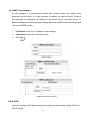
6.4.6.2 Logging Events Level
81B
User can select the system log events and SMTP events. When selected events occur,
the system will send out the log information. The range of Logging Event Level is from
level 0 to level 7. When the level value is the same as the one among Local Logging,
25
Remote Logging, and SMTP Logging, the system will issue a log record to location
where user has designated. After configuring, click Apply .
Logging Event Level: 4 events – Cold Start Event, Warm Start Event, Auth
Failure Event, and Port Link Change Event. Pull down the right side item menu to
select the event level. When selected events occur, the system will issue the logs.
Cold Start Event: when the device executes cold start action, the system will
issue a log event.
Warm Start Event: when the device executes warm start, the system will
issue a log event.
Auth Failure Event: You get this trap if a network management system
(NMS) polls the device with the wrong community string.
Port Link Change Event: when the port link has changed, the system will
issue a log event.
Logging Events Level interface
6.4.6.3 Logging RAM Table
82B
Logging RAM Table displays the logs which have been sent to RAM.
26
Logging RAM Table interface.
6.4.6.4 Logging Flash Table
83B
Logging Flash Table displays the logs which have been sent to Flash ROM.
Logging ROM Table interface
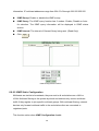
6.4.7 Security Manager
57B
Change login user name and password for the management security issue
User Name: Key in the new user name (The default is “admin”)
New Password: Key in the new password (The default is “admin”)
Confirm Password: Re-type the new password
And then, click Apply
27
6.5 Port
26B
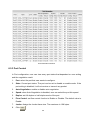
6.5.1 Port Statistics
58B
Display the port statistic information.
Port Statistic interface
6.5.2 Port Information
59B
The following information provides the current port statistic information
28
Port Information interface
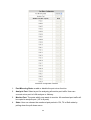
6.5.3 Port Control
60B
In Port configuration, user can view every port status that depended on user setting
and the negotiation result.
1.
Port: select the port that user wants to configure.
2.
State: Current port status. The port can be set to disable or enable mode. If the
port setting is disabled, it will not receive or transmit any packet.
3.
Auto Negotiation: enable or disable auto negotiation
4.
Speed: when Auto Negotiation is disabled, user can select the port link speed.
5.
Duplex: set full-duplex or half-duplex mode of the port.
6.
Flow Control: set flow control function is Enable or Disable. The default value is
Enable.
7.
Jumbo: Assign the Jumbo frame size. The maximum is 10K bytes.
8.
Click Apply .
29
Port Configuration interface
6.5.4 Port Trunk
61B
The Link Aggregation Control Protocol (LACP) provides a standardized means for
exchanging information between Partner Systems on a link to allow their Link
Aggregation Control instances to reach agreement on the identity of the Link
Aggregation Group to which the link belongs, move the link to that Link Aggregation
Group, and enable its transmission and reception functions in an orderly manner. Link
aggregation lets you group up to eight ports into two dedicated connections. This
feature can expand bandwidth between 2 (or more) devices. LACP operation requires
full-duplex mode, more detail information refers to IEEE 802.3ad.
6.5.4.1 Trunk Configuration
84B
1.
Group ID: list the Trunk group ID.
2.
Type: Static and LACP for selecting
3.
select the port number from the right column list and then click Add
add the port into a trunk group
30
button to
4.
Click Remove
button to remove the port from a trunk group
5.
To delete Trunk Group, select the Group Id and click
Delete
button.
Trunk Configuration interface
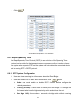
6.5.4.2 Trunk Information
85B
After setting up the trunk group, user will see the related information as below.
Trunk Information interface
6.5.4.3 Port Activity
86B
User will see the related information of LACP Port Activity State as below.
31
Port Activity interface
6.5.5 Port Mirror
62B
The port mirror is a method for monitor traffic in switched networks. Traffic through
ports can be monitored by specific port. That means traffic goes in or out monitored
ports will be duplicated into analysis port.
32
Port Mirror Configuration interface
1.
Port Mirroring State: enable or disable the port mirror function
2.
Analysis Port: Select a port for analyzing all monitor port traffic. User can
connect mirror port to LAN analyzer or Netxray.
3.
Monitor Port: The ports which user wants to monitor. All monitored port traffic will
be copied to analysis port. (UP to 8 ports)
4.
State: User can choose the monitored port packet in RX, TX or Both state by
pulling down the pull-down menu.
33
5.
Click Apply .
6.5.6 Rate Limiting
63B
User can set up the bandwidth rate and packet limitation type of each port.
Input
State: There are 4 check boxes of Bc, Mc, UnkUc, KnownUc for selecting.
Rate (1~1526)(Rate*655Kbps): Type in the input rate limit in number
between 1~1526.
Output
State: Enable or disable the output rate limit.
Rate (Rate*312Kbps): Type in the output rate limit which is a multiple of 312.
Port Configuration interface
6.6 Protocol
27B
6.6.1 VLAN
64B
A Virtual LAN (VLAN) is a logical network grouping that limits the broadcast domain,
which would allow you to isolate network traffic, so only the members of the VLAN will
receive traffic from the same members of VLAN. Basically, creating a VLAN from a
switch is logically equivalent of reconnecting a group of network devices to another
Layer 2 switch. However, all the network devices are still plugged into the same switch
34
physically.
6.6.1.1 VLAN Mode Configuration
87B
The switch supports port-based and 802.1Q (tagged-based) VLAN. The default
configuration of VLAN operation mode is “802.1Q”.
VLAN Mode Configuration interface
6.6.1.2 Port VLAN Id Configuration
8B
1.
Port: Select the port number in the table list.
2.
VLAN ID: Key in the VLAN ID.
3.
Ingress Filter: Enable or Disable the ingress filter.
4.
Acceptable Frame Type: Choose Tag only or All type.
5.
Click
Apply
Port VLAN Id Configuration interface
35
6.6.1.3 VLAN Entry
89B
Edit the existing VLAN Group.
1.
Select the VLAN group in the table list.
2.
Click
Edit
VLAN Table Configuration interface
3.
User can add/ remove the ports from a VLAN group.
4.
Click Next .
VLAN Table Configuration - Edit interface
5.
Mark the check box to tag the ports of a VLAN group.
36
6.
Click Apply .
VLAN Table Configuration - Edit interface
6.6.2 Rapid Spanning Tree
65B
The Rapid Spanning Tree Protocol (RSTP) is an evolution of the Spanning Tree
Protocol and provides for faster spanning tree convergence after a topology change.
The system also supports STP and the system will auto detect the connected device
that is running STP or RSTP protocol.
6.6.2.1 STP System Configuration
90B
User can view spanning tree information about the Root Bridge
User can modify RSTP state. After modification, click
Apply
button
Mode: user must enable or disable RSTP function before configure the
related parameters
Priority (0-61440): a value used to identify the root bridge. The bridge with
the lowest value has the highest priority and is selected as the root.
Max Age (6-40): the number of seconds a bridge waits without receiving
37
Spanning-tree Protocol configuration messages before attempting a
reconfiguration. Enter a value between 6 through 40
Hello Time (1-10): the time that controls switch sends out the BPDU packet
to check RSTP current status. Enter a value between 1 through 10
Forward Delay Time (4-30): the number of seconds a port waits before
changing from its Rapid Spanning-Tree Protocol learning and listening states
to the forwarding state. Enter a value between 4 through 30
[NOTE] Follow the rule to configure the MAX Age, Hello Time, and Forward
Delay Time.
2 x (Forward Delay Time value –1) > = Max Age value >= 2 x (Hello Time
value +1)
RSTP System Configuration interface
38
6.6.2.2 STP Port Configuration
91B
User can configure path cost and priority of every port.
1. Select the port in Port column.
1. Priority: Decide which port should be blocked by priority in LAN. Enter a number 0
through 240.
2. Path Cost: The cost of the path to the other bridge from this transmitting bridge at
the specified port. Enter a number 1 through 200000000.
3. AdmP2P: Some of the rapid state transactions that are possible within RSTP are
dependent upon whether the port concerned can only be connected to exactly one
other bridge (i.e. it is served by a point-to-point LAN segment), or can be
connected to two or more bridges (i.e. it is served by a shared medium LAN
segment). This function allows the P2P status of the link to be manipulated
administratively. Enable is P2P enabled; disable is P2P disabled; and auto means
auto-sense.
4. AdmEdge: The port directly connected to end stations which cannot create
bridging loop in the network. To configure the port as an edge port, set the port to
“Enable” status.
5. AdmStp: The port includes the STP mathematic calculation. Enable is including
STP mathematic calculation. Disable is not including the STP mathematic
calculation.
6. Click Apply .
39
RSTP Port Configuration interface
6.6.3 SNMP
6B
Simple Network Management Protocol (SNMP) is the protocol developed to manage
nodes (servers, workstations, routers, switches and hubs etc.) on an IP network.
SNMP enables network administrators to manage network performance, find and
solve network problems, and plan for network growth. Network management systems
learn of problems by receiving traps or change notices from network devices
implementing SNMP.
SNMP Information
Enter the system name, contact and location information.
Name: Assign a name for the switch.
Location: Type the location of the switch.
Contact: Type the name of contact person or organization.
SNMP Community String
User can define new community string set and remove unwanted community string.
RO: Read only. Enable requests accompanied by this string to display MIB-object
information.
RW: Read write. Enable requests accompanied by this string to display
MIB-object information and to set MIB objects.
40
SNMP Trap managers
A trap manager is a management station that receives traps, the system alerts
generated by the switch. If no trap manager is defined, no traps will issue. Create a
trap manager by entering the IP address of the station and a community string. To
define management stations as trap manager and enter SNMP community strings and
selects the SNMP version.
IP Address: enter the IP address of trap manager.
Community: enter the community string.
Click Add .
SNMP Configuration interface
6.6.4 QoS
67B
User can configure QoS policy and priority setting, per port priority setting, COS and
DSCP setting.
41
6.6.4.1 QoS Configuration
92B
Queue Profile: Select the queue profile from the column list.
Priority Precedence: There are 4 priority precedence selections available.
Click Adpply .
QoS Configuration interface
6.6.4.2 Port-bace Configuration
93B
Port: Select the number port from the column list.
Default Port Priority (0-7): Assign the priority level.
Click Adpply .
Port-base Configuration interface
42
6.6.4.3 COS Configuration
94B
Set up the COS priority level.
COS priority: Set up the COS priority level 0~7, 7 is the highest priority.
Click Apply .
COS Configuration interface
6.6.4.4 DSCP Configuration
95B
Set up the DSCP priority.
Mapping DSCP priority: The system provides 0~63 DSCP priority level. Each
level has 8 types of priority – 0~7, 7 is the highest priority. When the IP packet is
received, the system will check the DSCP level value in the IP packet that has been
received. For example: user set the DSCP level 25 as high. When the packet received,
the system will check the DSCP value of the received IP packet. If the DSCP value of
received IP packet is 25(priority = high), and then the packet priority will have highest
priority.
Click Apply .
43
DSCP Configuration interface
6.6.5 SNTP
68B
User can configure the SNTP (Simple Network Time Protocol) settings. The SNTP
allows user to synchronize switch clocks in the Internet.
1.
SNTP Server Link Status: Display the link status of SNTP server.
2.
Switch Current Time: Display the current time of the switch.
3.
SNTP Client: Enable or disable SNTP function. When it is enabled, user can
assign the domain name or IP address of SNTP server for getting the time from
SNTP server.
4.
UTC Timezone: Set the switch location time zone.
5.
SNTP Period: The SNTP period is used for sending synchronizing packets
periodically.
6.
SNTP Sever IP Address: Assign the SNTP server IP address.
7.
Click Apply .
44
SNTP Configuration interface
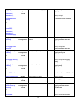
6.6.6 IGMP
69B
The Internet Group Management Protocol (IGMP) is an internal protocol of the Internet
Protocol (IP) suite. IP manages multicast traffic by using switches, routers, and hosts
that support IGMP. Enabling IGMP allows the ports to detect IGMP queries and report
packets and manage IP multicast traffic through the switch. IGMP have three
fundamental types of message as follows:
Message
Query
Description
A message sent from the querier (IGMP router or switch)
asking for a response from each host belonging to the
multicast group.
A message sent by a host to the querier to indicate that the
Join Group
host wants to be or is a member of a given group indicated in
the report message.
A message sent by a host to the querier to indicate that the
Leave Group
host has quit being a member of a specific multicast group.
6.6.6.1 IGMP Configuration
96B
The switch support IP multicast, user can enable IGMP protocol on web
management’s switch setting advanced page, then display the IGMP snooping
45
information. IP multicast addresses range from 224.0.0.0 through 239.255.255.255.
IGMP Snoop: Enable or disable the IGMP snoop.
IGMP Query: The IGMP query function has 3 modes - Enable, Disable or Auto for selection. The IGMP query information will be displayed in IGMP status
section.
IGMP interval: The interval of General Query being sent. (Read Only)
Click Apply .
IGMP Configuration interface
6.6.6.2 IGMP Static Configuration
97B
Multicasts are similar to broadcasts, they are sent to all end stations on a LAN or
VLAN. Multicast filtering is the system by which end stations only receive multicast
traffic if they register to join specific multicast groups. With multicast filtering, network
devices only forward multicast traffic to the end stations that are connected to
registered ports.
This function action when IGMP Configuration disable.
46
Port ID: Select the port number in the specific multicast group IP address.
VLAN ID: Input the value of VLAN ID.
IP Address: Assign a multicast group IP address in the range of 224.0.0.0 ~
239.255.255.255.
Click "Add".
If you want to delete an entry from table, select the entry and click "Delete".
IGMP Static Configuration interface
6.6.7 LLDP
70B
The Link Layer Discovery Protocol (LLDP) specified in this standard allows stations
attached to an IEEE 802 LAN to advertise, to other stations attached to the same IEEE
802 LAN, the major capabilities provided by the system incorporating that station, the
management address or addresses of the entity or entities that provide management
of those capabilities, and the identification of the station’s point of attachment to the
IEEE 802 LAN required by those management entity or entities.
6.6.7.1 LLDP Configuration
98B
Mode Configuration: Enable or disable the LLDP function.
Port Configuration: Enable or disable the LLDP state of the number port.
47
LLDP Configuration interface
6.6.7.2 LLDP Neighbor Table
9B
User will see all information of port by LLDP enable.
LLDP Neighbor Table interface
6.7 Security
28B
6.7.1 802.1x/ RADIAS
71B
802.1x is an IEEE authentication specification that allows a client to connect to a
wireless access point or wired switch but prevents the client from gaining access to the
port until it provides authority, like a user name and password that are verified by a
separate server.
6.7.1.1Misc Configuration
10B
1.
Mode: Enable or disable 802.1 x protocols.
2.
Quiet Period: Set the period during which the port doesn’t try to acquire a
supplicant.
3.
TX Period: Set the period the port waits for retransmit next EAPOL PDU during
an authentication session.
48
4.
Supplicant Timeout: Set the period of time the switch waits for a supplicant
response to an EAP request.
5.
Server Timeout: Set the period of time the switch waits for a server response to
an authentication request.
6.
ReAuthMax: Set the number of authentication that must time-out before
authentication fails and the authentication session ends.
7.
Reauth period: set the period of time after which clients connected must be
re-authenticated.
8.
Click Apply .
MISC Configuration interface
49
6.7.1.2 Port Configuration
10B
Port Configuration interface
You can configure 802.1x authentication state for each port. The State provides
Disable, Authorize, Accept and Reject.
Disable: This function is disabled.
Authorize: The specified port is set to the Authorized or Unauthorized state in
accordance with the outcome of an authentication exchange between the
supplicant and the authenticator.
Accept: The specified port will allow the client accessing in any case.
Reject: The specified port rejects the client accessing regardless of whether the
authentication passed or not.
Click Apply .
6.7.1.3Radius Client Configuration
102B
After having enabled the IEEE 802.1X function, user can configure the parameters of
this function.
1.
Radius Server IP: Set the Radius Server IP address.
2.
Server Port: Set the UDP destination port for authentication requests to the
specified Radius Server.
3.
Accounting Port: Set the UDP destination port for accounting requests to the
50
specified Radius Server.
4.
Shared Key: Set an encryption key for using during authentication sessions with
the specified radius server. This key must match the encryption key used on the
Radius Server.
5.
NAS Identifier: A string used to identify this switch.
6.
Click Apply .
6.7.2 Port Security
72B
Use the MAC address table to ensure the port security.
6.7.2.1 Static MAC Address Table
103B
User can add a static MAC address; it remains in the switch's address table,
regardless of whether the device is physically connected to the switch. This saves the
switch from having to re-learn a device's MAC address when the disconnected or
powered-off device is active on the network again. User can add / modify / delete a
static MAC address.
Packets with the specified destination address received in the specified VLAN are
forwarded to the specified interface.
Static MAC Addresses interface
Add the Static MAC Address
51
User can add static MAC address in switch MAC table.
1.
MAC Address Port VLAN ID: list the MAC Address Port. VLAN ID
2.
MAC Address: Specify the destination MAC address to add to the address table.
3.
Port.No: pull down the selection menu to select the port number.
4.
Vid: enter the Vid of the MAC address, it has to be between 1 to 4094.
5.
Click
6.
If user wants to delete the MAC address from filtering table, select the MAC
Add
.
address and click Delete .
6.7.2.2 Filter MAC Address Table
104B
MAC address filtering allows the switch to drop unwanted traffic. Traffic is filtered
based on the destination addresses. For example, if your network is congested
because of high utilization from one MAC address, you can filter all traffic transmitted
to that MAC address, restoring network flow while you troubleshoot the problem.
MAC Filtering interface
1.
MAC Address: Enter the MAC address that user wants to filter.
2.
Vid: enter the Vid of the MAC address, it has to be between 1 to 4094.
3.
Click
Add
.
52
4.
If user wants to delete the MAC address from filtering table, select the MAC
address and click Delete .
6.7.2.3 MAC Address Table Aging
105B
Aging Status: Pull-down menu to enable MAC address table aging function.
Aging Time (20~620): Assign the aging time in second.
Address Aging interface
6.7.3 IP Security
73B
User can assign up to 10 security IP addresses for accessing the switch via HTTP,
TELNET or both, any other IPs which are not included will be restricted.
IP Security interface
1.
Mode: When mode is set at ON, user can assign up to 10 Security IP addresses.
53
2.
HTTP: mark the check box to enable the access via HTTP for the assigned IP
3.
TELNET: mark the check box to enable the access via TELNET for the assigned
IP.
4.
Click
5.
And then, click Apply
Clear
button to clear IP address and all the check box.
6.7.4 ACL
74B
An ACL is a sequential list of permit or deny conditions that apply to IP addresses.
This switch tests ingress or egress packets against the conditions in an ACL one by
one. A packet will be accepted as soon as it matches a permit rule, or dropped as soon
as it matches a deny rule. If no rules match for a list of all permit rules, the packet is
dropped; and if no rules matches for a list of all deny rules, the packet is accepted.
The following restrictions apply to ACLs:
The ACL only support single port and not support trunk group.
The maximum number of ACLs is also 5 for each port.
Command Attributes
Enable: An ACL can be enable per port.
Default Action: The action if no rules matched.
Action: An ACL can be permit or deny rule.
IP Address and Prefix Length: Include destination and source IP address.
Ex: source 192.168.16.1/24 means all frames that source IP address is 192.168.16.x
matched.
54
Access Control Configuration Interface
6.8 Factory Default
29B
Reset switch to default configuration. Click ALL
default value or PART
to reset all configurations to the
to reset all configuration except reserved IP, user name and
password.
Factory Default interface
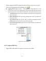
6.9 Save Configuration
30B
Save all configurations that user has made in the system. To ensure the all
configuration will be saved. Click Save Flash to save the all configuration to the flash
memory.
Please be noted, it is recommend to do the “save configuration” once changes has
been made on system.
Save Configuration interface
55
6.10 System Reboot
31B
Reboot the switch in software reset. Click
Reboot
to reboot the system.
System Reboot interface
56
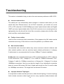
Troubleshooting
6B
This section is intended to help you solve the most common problems on MSL-3S79.
Incorrect connections
The switch port can automatically detect straight or crossover cable when you link
switch with other Ethernet device. As for RJ-45 connection, you should use correct
UTP or STP cable that 10/100/1000Mbps port uses 2-pairs twisted cable and Gigabit
1000T port uses 4 pairs twisted cable. If the RJ-45 connector is not correctly pinned on
right position then the link will fail. As for fiber connection, please notice the fiber cable
mode and fiber module should match.
Faulty or loose cables
Look for loose or obviously faulty connections. If they appear to be OK, make sure the
connections are snug. If that does not correct the problem, try a different cable.
Non-standard cables
Non-standard and miss-wired cables may cause numerous network collisions and
other network problem, and can seriously impair network performance. A category
5-cable tester is a recommended tool for every 100Base-T network installation.
RJ-45 ports: Use unshielded twisted-pair (UTP) or shield twisted-pair ( STP ) cable for
RJ-45 connections: 100Ω Category 3, 4 or 5 cable for 10Mbps connections, 100Ω
Category 5 cable for 100Mbps connections or Category-5e / Category-6 for above
1000Mbps connections. Also be sure that the length of any twisted-pair connection
does not exceed 100 meters (328 feet). Gigabit port should use Cat-5 or cat-5e cable
for 1000Mbps connections. The length does not exceed 100 meters.
Improper Network Topologies
It is important to make sure that you have a valid network topology. Common topology
faults include excessive cable length and too many repeaters (hubs) between end
57
nodes. In addition, you should make sure that your network topology contains no data
path loops. Between any two ends nodes, there should be only one active cabling path
at any time. Data path loops will cause broadcast storms that will severely impact your
network performance.
Diagnosing LED Indicators
The Switch can be easily monitored through panel indicators, which describes
common problems you may encounter and where you can find possible solutions to
assist in identifying problems.
If the power indicator is not lighted when the power cord is plugged in, you may have a
problem with power outlet, or power cord. However, if the switch powers off after
running for a while check for loose power connections, power losses or surges at
power outlet. If you still cannot resolve the problem, contact your local dealer for
assistance.
58
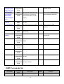
Appendix A- Command Sets
7B
Commands Set List
32B
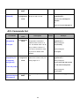
Modes
Access Method
Prompt
Exit Method
About This Model
The user commands
available at the user level
are a subset of those
User EXEC
Begin a session with
your switch.
switch>
Enter logout or
quit.
available at the privileged
level.
Use this mode to
• Perform basic tests.
• Display system
information.
The privileged command
Privileged
EXEC
is advance mode
Enter the enable
command while in
switch#
user EXEC mode.
Enter disable to
Privileged this mode to
exit.
• Display advance
function status
• save configures
Global
configuration
VLAN
database
Enter the configure
command while in
switch(config)#
privileged EXEC mode.
Enter the vlan database
command while in
switch(vlan)#
privileged EXEC mode.
To exit to
Use this mode to
privileged
configure
EXEC mode,
Parameters that apply to
enter exit or end
your switch as a whole.
To exit to user
Use this mode to
EXEC mode,
configure
enter
VLAN-specific
Exit.
parameters.
To exit to global
Interface
configuration
Enter the interface
Configuration
command (with a
mode, enter exit.
specific interface) while
switch(config-if)#
To exist to
in global configuration
privileged
mode
EXEC mode or
end.
59
Use this mode to
configure
Parameters for the switch
and Ethernet ports.
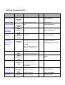
System Commands Set
3B
Commands
Command
Description
Defaults
Example
Level
system name
[system name]
Global
Set switch system name string
switch(config)#
system name xxx
configuration
mode
system location
[system Location]
Global
Set switch system location
switch(config)#
system location xxx
configuration string
mode
system
description
[description]
system contact
[contact]
Global
Set switch system description
switch(config)#
system description xxx
configuration string
mode
Global
Set switch system contact
switch(config)#
system contact xxx
configuration window string
mode
ip address
[ip-address]
[subnet-mask]
Global
Use the ip address interface
configuration configuration command to set
an IP address for a switch. Use
mode
[gateway]
switch(config)#
ip address 192.168.1.1
255.255.255.0 192.168.1.254
the no form
of this command to remove an
IP address or to disable IP
processing.
write memory
reload
Privileged
Save user configuration into
EXEC
permanent memory(flash rom)
Global
Halt and perform a cold restart
switch#write memory
switch(config)#
reload
configuration
mode
default
Global
Restore to default
switch(config)#default
configuration no: restore all to default.
yes: reserved ip, username
mode
and password.
admin username
[Username]
Global
Changes a login username.
configuration (maximum 32 words)
switch(config)#admin
username xxxxxx
mode
admin password
[Username]
Global
Specifies a password
configuration (maximum 32 words)
60
switch(config)#admin
password xxxxxx
mode
console-timeout
[time(sec)]
Global
Set console timeout. The range 180 sec
configuration of timeout is 30 sec ~ 600 sec.
switch(config)#console-timeout
30
mode
show system-info
Privileged
Show system information
switch#show system-info
Show ip information of switch
switch#show ip
Show username & password
switch#show admin
Privileged
Use the show version user
switch# show version
EXEC
EXEC command to display
EXEC
show ip
Privileged
EXEC
show admin
Privileged
EXEC
show version
version information for the
hardware and firmware.
show terminal
Privileged
EXEC
Use the show terminal
switch#show terminal
command to display console
information for the switch
show fan-status
Privileged
EXEC
Use the show fan-status
switch(config)#
command to display fan status
show fan-status
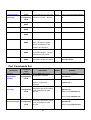
Port Commands Set
34B
Commands
interface
gigaethernet
[port ID]
Command
Level
Interface
configuration
mode
Description
Default
Example
Use the Ethernet interface
configuration command
switch(config)#interface
Use the module Ethernet
switch(config)#interface
interface configuration
gigaethernet 1
gigaethernet 1
command
duplex
[full | half]
Interface
Use the duplex configuration
configuration command to specify the duplex
mode of operation for Fast
mode
Ethernet.
Auto
switch(config)#interface
gigaethernet 1
switch(config-if)#duplex full
or
switch(config-if)#duplex half
speed
[10|100|1000|auto]
Interface
Use the speed configuration
configuration command to specify the speed
mode of operation for Fast
mode
Ethernet.
switch(config)#interface
gigaethernet 1
switch(config-if)#speed 1000
or
61
switch(config-if)#speed 100
or
switch(config-if)#speed 10
or
switch(config-if)#speed auto
flowcontrol
Interface
[enable|disable]
jumbo [size]
Use the flowcontrol
configuration configuration command on
Ethernet ports to control traffic
mode
rates during congestion.
Use the no form of this
command to disable security on
the port.
Configure flow control
Disable flow control of interface
Interface
Set jumbo frame size.
configuration Use the no form of this
mode
command to default value.
Off
switch(config)#interface
gigaethernet 1
switch(config-if)#flowcontrol
enable
or
switch(config-if)#flowcontrol
disable
1522
switch(config)#interface
gigaethernet 1
switch(config-if)# jumbo 1524
or
[Jumbo size must be even and
switch(config-if)# jumbo 10240
between 1522~10240]
rate-limit
Interface
input-mode
Set rate-limit input mode.
configuration You can enable rate-limit for
{bc|mc|unkuc|kno
mode
Disable switch(config)#interface
gigaethernet 1
specific packets such as
switch(config-if)#
wnuc}
broadcast, multicast, unknown
rate-limit input-mode bc
or
unicast and known unicast.
or
no rate-limit
Use the no form of this
switch(config-if)#
input-mode
command to disable for that
no rate-limit input-mode bc
{bc|mc|unkuc|kno
packets
or
wnuc}
switch(config-if)#
rate-limit input-mode mc
or
switch(config-if)#
no rate-limit input-mode mc
rate-limit
input-rate
Interface
Set rate-limit input rate value.
[value] configuration
mode
rate-limit
output-mode
or
Interface
gigaethernet 1
Input rate limit must be
switch(config-if)#
between 1~1526
rate-limit input-rate 1000
Set rate-limit output mode.
configuration You can enable output
mode
Disable switch(config)#interface
Disable switch(config)#interface
gigaethernet 1
rate-limit.
switch (config-if)#
no rate-limit
Use the no form of this
rate-limit output-mode
output-mode
command to disable output rate
switch (config-if)#
62
no rate-limit output-mode
limit.
rate-limit
output-rate
[value]
Interface
Set rate-limit output rate
Disable switch (config)#interface
configuration value.
mode
gigaethernet 1
Range is 1~3130 for 312Kbps
switch (config-if)#
unit on the port.
rate-limit output-rate 1000
Output rate limit must be
between 1~3130
shutdown
Interface
Use the shutdown
Enable
configuration Interface configuration
or
no shutdown
show interfaces
status
mode
Privileged
EXEC
switch (config)#interface
gigaethernet 1
command to disable the port.
switch(config-if)#
Use the no shutdown form of
shutdown
this command to enable the
switch(config-if)#
port.
no shutdown
Show interface configuration
switch #
status and configuration.
show interfaces status
[gigaethernet|port-
gigaethernet 1
channel|vlan]
or
[if-num]
switch #
show interfaces status portchannel 1
or
switch #
show interfaces status vlan 1
show interfaces
counters
Privileged
EXEC
Show interface statistic
switch #
counter.
show interfaces counters
[gigaethernet|port-
gigaethernet 1
channel] [if-num]
or
switch #
show interfaces counters
port-channel 1
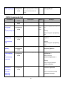
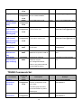
Mac / Filter Table Commands Set
35B
Commands
mac-address-table
aging-time [sec.]
or
Command
Level
Global
Description
Use the mactbl aging-time
configuration global configuration command
mode
to set the length of time that a
63
Default
Example
300 secs (Enable)
switch(config)#
mac-address-table aging-time
no
dynamic entry remains in the
150
mac-address-table
MAC address table after the
(Disable)
aging-time
entry is used or updated.
switch(config)#
Range: 0-300 seconds; 0 to
mac-address-table aging-time
disable aging)
0
(Default)
Use the no form of this
switch(config)#
command to use the default
no mac-address-table
aging-time interval. The aging
aging-time
time applies to all VLANs.
time must be 20~620 and in
steps of 20 seconds
mac-address-table
static hwaddr
Interface
Configure MAC address table
configuration
of interface (static)
mode
[MAC] vlan
witch (config)#interface
gigaethernet 1
switch(config-if)#mac-address-t
[VLAN-ID]
Remove an entry of MAC
able static hwaddr
or
address table of interface
000012345678 vlan 1
no
(static)
or
mac-address-table
witch (config)#interface
static hwaddr
gigaethernet 1
[MAC] vlan
switch(config-if)#no
[VLAN-ID]
mac-address-table static
hwaddr 000012345678 vlan 1
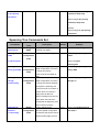
mac-address-table
filter hwaddr
Global
Configure MAC address
configuration
table(filter)
mode
[MAC] vlan
switch(config)#mac-address-ta
ble filter hwaddr 000012348678
vlan 1
[VLAN-ID]
Remove an entry of MAC
or
or
address table (filter)
switch(config)#no
no
mac-address-table filter
mac-address-table
hwaddr 000012348678 vlan 1
filter hwaddr
[MAC] vlan
[VLAN-ID]
show
mac-address-table
[static|filter|all]
or
show
mac-address-table
static
or
show
Privileged
EXEC mode
Show static MAC address table
Show filter MAC address table.
switch#show
mac-address-table static
or
Show all MAC address table
switch#show
mac-address-table filter
or
64
mac-address-table
filter
or
show
mac-address-table
all
show
mac-address-table
aging-time
switch#show
mac-address-table
Privileged
EXEC mode
all
switch#show
Show current aging time setup
mac-address-table aging-time
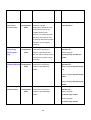
Port Mirroring Commands Set
36B
Commands
monitor
[port number]
[rx | tx | both]
Command
Description
Level
Default
Interface
Use the port monitor interface
configuration
configuration command to
mode
enable Switch Port Analyzer
Example
switch(config)#interface
gigaethernet 1
switch(config-if)#monitor 3 both
or
(SPAN) port
or
no monitor [port
monitoring on a port. Use the
switch(config-if)#no monitor 3
number| all]
no form of this command to
or
return the port to its default
(Disable)
value.
switch(config-if)#
no monitor all
show monitor
Privileged
Show port monitor information
switch#show monitor
EXEC
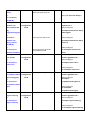
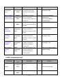
TFTP Commands Set
37B
Commands
backup
flash:backup_cfg
Command
Level
Global
Description
Save configuration to TFTP
configuration server and need to specify the
mode
Default
Example
switch(config)#backup
flash:backup_cfg
IP of TFTP server and the file
name of image.
restore
flash:restore_cfg
Global
Get configuration from TFTP
configuration
server and need to specify the
mode
IP of TFTP server and the file
name of image.
switch(config)#restore
flash:restore_cfg
TFTP server ip address
[192.168.16.2]:
Restore file name [restore.dat]:
*config success.*
65
upgrade
flash:upgrade_fw
Global
switch(config)#upgrade
Upgrade firmware by TFTP and
configuration need to specify the IP of TFTP
mode
lash:upgrade_fw
server and the file name of
image.
QOS Commands Set
38B
Commands
show qos
Command
Level
Privileged
Description
Default
Example
switch#show qos
Show QoS settings
EXEC
qos priority cos
[Cos] [Qid]
or
Global
Qid =
switch(config)#qos priority cos
configuration
Traffic
02
mode
Class
or
Configure COS Priority
no qos priority cos
(Default)
switch(config)# no qos priority
cos
qos priority dscp
[dscp] [Qid]
or
Global
switch(config)# qos priority
Set DSCP Map
configuration
dscp 61 5
mode
or
no qos priority
(Default)
dscp
switch(config)# no qos priority
dscp
qos priority profile
[profile]
Global
Set Qos Port Profile [0~3]
0
configuration
switch(config)#
qos priority profile 3
mode
qos priority
portbased[Qid]
or
Interface
Set Qos Port Priority [0~7]
configuration
0
witch(config)#interface
gigaethernet 1
mode
switch(config-if)#
no qos priority
qos priority portbased 3
portbased
or
(Default)
switch(config-if)# no qos
priority portbased
qos priority
Global
precedence
configuration
[port-base|
mode
Set Priority Precedence
Port-base switch(config)# qos priority
precedence port-base
or
cos-only|
switch(config)# qos priority
dscp-only|
precedence cos-only
dscp-first]
or
66
or
switch(config)# qos priority
no qos priority
precedence dscp-only
precedence
or
switch(config)# qos priority
precedence dscp-first
or
(Default)
switch(config)# no qos priority
precedence
Spanning Tree Commands Set
39B
Commands
show
Command
Level
Privileged
Description
EXEC
spanning-tree states.
spanning-tree
Global
Enable/disable spanning tree
or
Example
switch#show spanning-tree
Display a summary of the
spanning-tree
enable
Default
Disable switch(config)#spanning-tree
configuration
enable
mode
or
no spanning-tree
switch(config)#no
spanning-tree
spanning-tree
Global
spanning-tree
Use the spanning-tree priority
global configuration command
configuration
to change the priority.
mode
Priority must be a multiple of
4096
Global
Use the spanning-tree max-age
max-age
configuration global configuration command
priority [0~61440]
[6~40seconds]
mode
32768
switch(config)#spanning-tree
priority 4096
20 sec
switch(config)#spanning-tree
max-age 15
to change the interval between
messages the spanning tree
receives from the root switch. If
a switch does not receive a
bridge protocol data unit
(BPDU) message from the root
switch within this interval, it
recomputed the Spanning Tree
Protocol (STP) topology.
spanning-tree
hello-time
[1~10seconds]
Global
Use the spanning-tree
configuration hello-time global configuration
mode
command to specify the interval
between hello bridge protocol
67
2 sec.
switch(config)#spanning-tree
hello-time 3
data units (BPDUs).
spanning-tree
forward-time
[4~30seconds]
Global
Use the spanning-tree
15 sec. switch(config)#spanning-tree
configuration forward-time global
mode
forward-time 20
configuration command to set
the forwarding-time for the
specified spanning-tree
instances. The forwarding time
determines how long each of
the listening and learning states
last before the port begins
forwarding.
stp-port priority
[port priority]
pathcost [path
Interface
Use the stp-port interface
128
configuration configuration command to
mode
cost]
switch(config)#interface
gigaethernet 1
configure a port priority and
switch(config-if)#
path cost that is used when two
stp-port priority 16 pathcost
switches tie for position as the
200000
root switch.
stp-admin-p2p
Interface
Use the stp-admp2p interface
Enable
switch (config)#interface
[disable|enable|aut configuration configuration command to
gigaethernet 1
o]
configure a port AdmP2P
switch(config-if)# stp-admin-p2p
variable.
auto
mode
or
switch(config-if)# stp-admin-p2p
enable
or
switch(config-if)# stp-admin-p2p
disable
stp-admin-edge
[disable|enable]
Interface
Use the stp-admedge interface Enable
configuration configuration command to
mode
switch (config)#interface
gigaethernet 1
configure a port AdmEdge
switch(config-if)#
variable.
stp-admin-edge enable
or
switch(config-if)#
stp-admin-edge disable
68
stp-admin- stp
[disable|enable]
Interface
Use the stp-admstp interface
Enable
configuration configuration command to
mode
switch (config)#interface
gigaethernet 1
configure a port controlled by
switch(config-if)# stp-admin stp
stp protocol.
enable
VLAN Commands Set
40B
Commands
vlan database
Command
Level
Privileged
Description
Default
switch#vlan database
Enter VLAN configure mode
EXEC
vlanmode
switch(vlan)#
VLAN database To set switch VLAN mode.
[portbase| 802.1q|
Example
mode
8021q
switch(vlan)#vlanmode
portbase
gvrp ]
or
switch(vlan)#vlanmode 802.1q
or
switch(vlan)#vlanmode gvrp
show vlan
or
show vlan
[GroupName|
VLAN ID]
VLAN database Show VLAN information
mode
switch(vlan)#show vlan
or
switch(vlan)#show vlan 2
Port Base VLAN mode
no vlan group
[VLAN ID]
VLAN database Delete port base group ID
vlan port-based
VLAN database Add new port based VALN
grpname
switch(vlan)#no vlan group 2
mode
mode
switch(vlan)#vlan port-based
grpname test grpid 2 port 2-4
[Group Name]
or
grpid
switch(vlan)#vlan port-based
[VLAN ID]
grpname test grpid 2 port 2,3,4
port
[PortNumbers]
802.1Q | 802.1Q with GVRP VLAN mode*
vlan 8021q name
[GroupName] vid
[VLAN ID] media
VLAN database Change the name of VLAN
mode
switch(vlan)#
group, if the group didn’t exist,
vlan 8021q name RD vid 2
this command can’t be applied.
media gigaethernet state
69
gigaethernet state
or
active
active
Delete port base group ID
or
switch(vlan)#no vlan 8021q 2
or
no vlan 8021q
[VLAN ID]
switchport
allowed vlan
8021q add [VLAN
Interface
witch(config)#interface
Add port to the VLAN
configuration
gigaethernet 1
mode
switch(config-if)#
ID]
switchport allowed vlan 8021q
[tagged|untagged]
add 2 tagged
or
or
switchport
Remove port to the VLAN
switch(config-if)#
allowed vlan
switchport allowed vlan 8021q
8021q remove
remove 2
[VLAN ID]
or
or
switch(config-if)#
Remove port from all VLAN
except default VLAN
no switchport
no switchport allowed vlan
allowed vlan8021q
switchport native
vlan [PVID]
or
8021q
Interface
Set Port PVID
1
configuration
switch(config)#
interface gigaethernet 1
mode
switch(config-if)#
no switchport
switchport native vlan 2
native vlan
or
switch(config-if)#
no switchport native vlan
switchport
Interface
Set accept frame type
all
switch(config)#
acceptable-frame-t configuration
interface gigaethernet 1
ypes [all|tagged]
switch(config-if)#
switchport
mode
or
acceptable-frame-types all
no switchport
or
acceptable-frame-t
switch(config-if)#
no switchport
ypes
acceptable-frame-types
switchport
ingress-filtering
or
Interface
Set ingress filter
configuration
disable switch(config)#
interface gigaethernet 1
mode
switch(config-if)#
no switchport
switchport ingress-filtering
ingress-filtering
or
switch(config-if)#
no switchport ingress-filtering
70
show vlan
Privileged
[id|name]
EXEC
[VLAN ID | Name]
show interfaces
switchport
switch#show vlan id
Show VLAN of Group Name or
VLAN ID information
vlanid: 1 ~ 4094
Privileged
EXEC
show Port PVID and ingress
switch#
filter & accept frame type
show interfaces switchport
[gigaethernet|port-
gigaethernet 1
channel] [port]
*Future Release
System log Commands Set
41B
Commands
Command
Level
show logging
Privileged
[flash | ram |
EXEC
Description
Default
Example
Show system log information
switch# show logging flash
Enable logging mode for local,
Switch(config)#
sendmail | trap|
map]
logging-mode
{local|remote|smt
p}
Global
configuration remote and smtp
logging-mode local
mode
or
Switch(config)#
no logging-mode local
no logging-mode
{local|remote|smt
Switch(config)#
p}
logging-mode remote
logging-local
history [flash |
ram] [level]
Global
Set system log level
configuration
Flash:3(le Switch(config)#
vel 3-0)
mode
RAM:7(lev
or
el 7-0)
no logging-local
history [flash |
ram]
71
logging-local history flash 3
logging-events
[coldstart |
warmstart |
Global
Set the level of each logging
Level 7
configuration events.
Switch(config)#
logging-events coldstart 3
mode
authfailure |
Switch(config)#
portlinkchange]
no logging-events coldstart
[level]
or
no logging-events
[coldstart |
warmstart |
authfailure |
portlinkchange]
Logging-host
[server]
or
Global
Add or delete the remote server
Switch(config)#
configuration address
logging-host 192.168.16.5
mode
no logging-host
Switch(config)# no
[server]
logging-host 192.168.16.5
logging facility
[value]
or
Global
Set system log facility
23
configuration
Switch(config)#
logging facility 19
mode
Switch(config)# no logging
no logging facility
facility
logging trap
[value]
or
Global
Set system log trap
configuration
7
Switch(config)#
logging trap 4
mode
no logging trap
Switch(config)# no logging trap
4
clear logging-local
[flash | ram]
Global
Clear system log buffer
configuration
Switch(config)#
clear logging-local flash
mode
logging sendmail
{host-0|host-1}
[server]
Global
Set the SMTP server address
configuration
Switch(config)#
logging sendmail host-0
mode
192.168.16.5
or
no logging
Switch(config)# no logging
72
sendmail
sendmail host-0 192.168.16.5
{host-0|host-1}
logging sendmail
level [value]
Global
Set system log SMTP level
7
Switch(config)#
configuration
logging sendmail level 4
mode
or
no logging
Switch(config)# no logging
sendmail level
sendmail level 4
logging sendmail
{src-0|src-1}
[email addr]
Global
Set system log SMTP
Switch(config)#
configuration source-email address
logging sendmail src-0
mode
[email protected]
or
no logging
Switch(config)# no logging
sendmail
sendmail src-0
{src-0|src-1}
[email protected]
logging sendmail
{dst-0|dst-1}
[email addr]
Global
Add or delete system log SMTP
Switch(config)#
configuration destination-email address
logging sendmail dst-0
mode
[email protected]
or
no logging
Switch(config)# no logging
sendmail
sendmail dst-0
{dst-0|dst-1}
[email protected]
[email addr]
logging sendmail
service
Global
Enable or disable system log
Disable
configuration SMTP
Switch(config)#
logging sendmail service
mode
or
no logging
Switch(config)#
sendmail service
No logging sendmail service
SNTP Commands Set
42B
Commands
Command
Level
Description
73
Default
Example
calendar set
Global
[hour] [min] [sec]
configuration
[day] [mon] [year]
mode
sntp timezone
Global
hours [hours]
minute [min]
switch(config)# calendar set 15
Set system time
03 30 29 4 2006
switch(config)# sntp timezone
Set timezone index, use “show
hours 9 minute 0 after-UTC
configuration sntp timezone” command to
mode
[after-UTC|before-
get more information of index
number
UTC]
show sntp
Privileged
switch#show sntp timezone
Show index number of time
timezone
EXEC
zone list
no sntp timezone
Global
Set system time zone to default (GMT+08: switch(config)# no sntp
configuration
00)
timezone
mode
show sntp
sntp server
[ipaddr]
Privileged
switch# show sntp
Show system time
EXEC
configuration.
Global
Set SNTP server IP address.
switch(config)# sntp server
configuration
192.168.16.5
mode
no sntp server
Global
Set SNTP server IP address to NULL
switch(config)# no sntp server
configuration default.
mode
sntp enable
Global
Enable SNTP Client.
switch(config)#sntp enable
Disable SNTP Client.
switch(config)#no sntp
Set SNTP client polling interval 16
switch(config)# sntp poll 60
configuration
mode
no sntp
Global
configuration
mode
sntp poll [sec]
Global
configuration seconds.
mode
no sntp poll
Global
Set SNTP client polling interval
switch(config)# no sntp poll
configuration seconds to default.
mode
IGMP Commands Set
43B
Commands
igmp enable
Command
Level
Global
Description
Enable IP IGMP Snooping
74
Default
disable
Example
switch(config)#igmp enable
configuration service.
mode
no igmp
Global
switch(config)#no igmp
Disable IP IGMP Snooping
configuration service to default disable.
mode
igmp-query
{enable |disable
Global
mode
igmp vlan [vid]
Global
[gigaethernet|port-
disable
switch(config)#igmp-query auto
configuration
|auto}
static [ipaddr]
Set IP IGMP query mode.
Adds a static multicast group
configuration and its member port.
mode
switch(config)# igmp vlan 1
static 224.0.0.251 gigaethernet
1
channel] [port]
no igmp vlan [vid]
static [ipaddr]
[gigaethernet|port-
Global
Remove a static multicast
configuration group and its member port.
mode
switch(config)# no igmp vlan 1
static 224.0.0.251 gigaethernet
1
channel] [port]
show igmp
Privileged
configuration
EXEC
show mactbl
Privileged
multicast vlan
EXEC
Displays the details of an IGMP
switch#show igmp
configuration
configuration
Shows known multicast
switch#show mactbl multicast
addresses for specific VLAN Id.
vlan 1
Shows known multicast
switch#show mactbl multicast
addresses only the
user
[vid]
show mactbl
multicast [user |
Privileged
EXEC
igmp-snooping]
user-configured multicast
entries or only entries learned
through IGMP snooping.
TRUNK Commands Set
4B
Commands
interface
port-channel
[group id]
Command
Level
Global
Description
Configures a trunk and enters
configuration interface configuration mode
mode
Example
switch(config)# interface
port-channel 1
for the trunk.
If the trunk group isn’t exist,
you should create it by add a
member port
no interface
Global
port-channel
configuration
Delete the trucking group.
switch(config)# no interface
port-channel 1
75
[group id]
trunk mode
[lacp|static]
mode
Interface
Configure the mode of the
static
configuration trunk group.
port-channel 1
mode
or
switch(config)# interface
switch(config-if)#
no trunk mode
trunk mode static
or
switch(config-if)#
no trunk mode
channel-group
[group id]
Interface
switch(config)# interface
Adds a port to a trunk.
configuration If the trunk group doesn’t exist,
it will create the group.
mode
gigaethernet 1
switch(config-if)#
channel-group 1
no channel-group
Interface
switch(config)# interface
Remove a port from a trunk.
configuration
gigaethernet 1
mode
switch(config-if)#
no channel-group 1
show interfaces
status
Privileged
switch# show interfaces status
Shows trunk information
EXEC
port-channel 1
port-channel
[group id]
show port activity
Privileged
EXEC
port
Interface
{active|passive}
Show lacp port activity
active
switch#show port activity
information
switch(config)# interface
Set port active|passive
configuration
gigaethernet 1
mode
switch(config-if)# port passive
SNMP Commands Set
45B
Commands
snmp name
[station name]
Command
Level
Global
Description
Configure station name.
configuration
Default
Example
switch(config)# snmp name
station1
mode
snmp location
[station location]
Global
Configure station location.
configuration
switch(config)# snmp location
Taiwan
mode
snmp contact
[station contact]
Global
Configure station contact.
configuration
switch(config)# snmp
contact [email protected]
HU
mode
76
UH
snmp
community-string
s [Community]
Global
Add SNMP community string.
configuration
mode
public, switch(config)#snmp
private community-strings public
right rw
right [RO/RW]
no snmp
community-string
Global
configuration community.
s [Community]
mode
snmp-server host
Global
[IP address]
community
Remove the specified
switch(config)#no snmp
community-strings public
Configure SNMP trap manager
configuration information and community
switch(config)#snmp-server
host 192.168.1.50 community
mode
string
public
Global
Remove the SNMP server
switch(config)#no snmp-server
[Community-strin
g]
no snmp-server
host
[Host-address]
show snmp
configuration host.
host 192.168.1.50
mode
Privileged
Show snmp configuration
switch#show snmp
EXEC
DHCP Server Commands Set
46B
Commands
dhcpserver [ip
start] [ip number]
Command
Level
Global
Description
Enable dhcp server and add
configuration lease entry.
Example
switch(config)#dhcpserver
192.168.1.5 5
mode
Netmask [255.255.255.0]:
255.255.255.0
Gateway [192.168.16.254]:
192.168.16.254
DNS [192.168.16.254]:
192.168.16.254
Lease Duration [24](hours)
24
no dhcpserver
Global
Disable dhcp server.
switch(config)#no dhcpserver
Show configuration of dhcp
switch#show dhcpserver
configuration
mode
show dhcpserver
Privileged
EXEC
server and client status.
77
Security IP Commands Set
47B
Commands
security [entry id]
Command
Level
Global
Description
Default
switch(config)# security 1 ip
Enable and add security ip.
ip [ip address] http configuration Entry id: 1 - 10
[on/off] telnet
Example
192.168.16.5 http on telnet on
mode
[on/off]
no security
Global
Disable IP security function
switch(config)#no security
Show the information of IP
switch#show security
configuration
mode
show security
Privileged
EXEC
security
802.1X Commands Set
48B
Commands
8021x enable
Command
Level
Global
Description
Use the 802.1x global
Example
Disable switch(config)# 8021x enable
configuration configuration command to
8021x misc
quietperiod
[sec.]
mode
enable 802.1x protocols.
Global
Use the 802.1x misc quiet
60
configuration period global configuration
mode
switch(config)# 8021x misc
quietperiod 10
command to specify the quiet
period value of the switch.
8021x misc
txperiod
Global
Use the 802.1x misc TX period
configuration global configuration command
[sec.]
mode
to set the TX period.
8021x misc
Global
Use the 802.1x misc supp
supportimeout
[sec.]
30
txperiod 5
30
configuration timeout global configuration
mode
switch(config)# 8021x misc
switch(config)# 8021x misc
supportimeout 20
command to set the supplicant
timeout.
8021x misc
servertimeout
[sec.]
Global
Use the 802.1x misc server
30
configuration timeout global configuration
mode
switch(config)#8021x misc
servertimeout 20
command to set the server
timeout.
8021x misc
maxrequest
[number]
Global
Use the 802.1x misc max
configuration request global configuration
mode
command to set the MAX
78
2
switch(config)# 8021x misc
maxrequest 3
requests.
8021x misc
reauthperiod
[sec.]
Global
Use the 802.1x misc reauth
3600
configuration period global configuration
mode
switch(config)# 8021x misc
reauthperiod 3000
command to set the reauth
period.
8021x
portstate
[disable | reject |
accept | authorize]
show 8021x
Interface
Use the 802.1x port state
Disable switch(config)# interface
configuration interface configuration
mode
Privileged
EXEC
gigaethernet 1
command to set the state of the
switch(config-if)#8021x
selected port.
portstate accept
Displays a summary of the
switch#show 8021x
802.1x properties and also the
port status.
8021x system
Global
Use the 802.1x system radius
switch(config)# 8021x system
radiusip
configuration
IP global configuration
radiusip 192.168.1.1
[IP address]
mode
command to change the radius
server IP.
8021x system
Global
Use the 802.1x system server
switch(config)# 8021x system
serverport
configuration
port global configuration
serverport
[port ID]
mode
command to change the radius
1815
server port
8021x system
Global
Use the 802.1x system account
switch(config)# 8021x system
accountport
configuration
port global configuration
accountport
[port ID]
mode
command to change the
816
accounting port
8021x system
Global
Use the 802.1x system share
switch(config)# 8021x system
sharekey
configuration
key global configuration
sharekey 123456
[ID]
mode
command to change the
shared key value.
LLDP Commands Set
49B
Commands
lldp [enable]
or
no lldp
show lldp status
Command
Description
Level
Global
Enable or disable LLDP
configuration protocol.
Disable
Example
switch(config)# lldp enable
or
mode
Privileged
Default
switch(config)# no lldp
Show LLDP status.
EXEC
79
switch# show lldp status
show lldp remote
Privileged
switch# show lldp remote
Show LLDP remote table.
EXEC
lldp-port [disable
|rx|tx|both]
Interface
Use those commands to set
Disable
switch(config)# interface
configuration lldp port tx and rx mode.
gigaethernet 1
mode
switch(config-if)# lldp-port
disable
or
switch(config-if)# lldp-port rx
50B
ACL Commands Set
Commands
acl-port
[deny|permit]
or
Command
Description
Level
Interface
Use the acl-port interface
configuration
configuration command to
mode
enable Access Control on a
no acl-port
Defaults
Disable
Example
switch(config)# interface
gigaethernet 1
switch(config-if)#
port. The default action can be
acl-port deny
Deny or Permit. Use the no
or
form of this command to return
switch(config-if)#
the port to its default value
no acl-port
(disable).
acl-rule [index] dst
[dstIp/prefix] src
[srcIp/prefix]
Interface
Use those commands to add or N/A
configuration delete the acl rules of the port.
mode
switch(config)# interface
gigaethernet 1
switch(config-if)#
[index] range= 0~4
{deny|permit}
acl-rule 0 dst 192.168.16.1/32
or
src 192.168.16.2/32 permit
no acl-rule [index]
or
switch(config-if)#
no acl-rule 0
show acl
[gigaethernet|port-
Privileged
EXEC
Show acl configuration of the
N/A
switch# show acl gigaethernet
1
port.
channel][port]
80