1
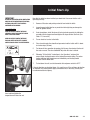
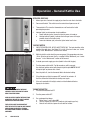
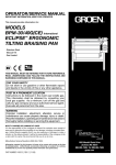
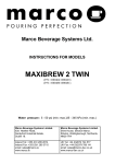
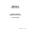
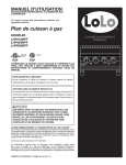
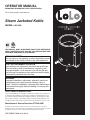
OPERATOR MANUAL
IMPORTANT INFORMATION, KEEP FOR OPERATOR
This manual provides information for:
Steam Jacketed Kettle
MODEL: LKS-45G
THIS MANUAL MUST BE RETAINED FOR FUTURE REFERENCE.
READ, UNDERSTAND AND FOLLOW THE INSTRUCTIONS AND
WARNINGS CONTAINED IN THIS MANUAL.
FOR YOUR SAFETY
Do not store or use gasoline or other flammable vapors
and liquids in the vicinity of this or any other appliance.
POST IN A PROMINENT LOCATION
Instructions to be followed in the event user smells gas.
This information shall be obtained by consulting your
local gas supplier. As a minimum, turn off the gas and
call your gas company and your authorized service agent.
Evacuate all personnel from the area.
WARNING
Improper installation, adjustment, alteration, service or
maintenance can cause property damage, injury or
death. Read the installation, operating and maintenance
instructions thoroughly before installing or servicing this
equipment.
NOTIFY CARRIER OF DAMAGE AT ONCE
It is the responsibility of the consignee to inspect the container upon receipt and
to determine the possibility of any damage, including concealed damage. LoLo
Commercial Foodservice Equipment suggests that if you are suspicious of damage to make a notation on the delivery receipt. It will be the responsibility of the
consignee to file a claim with the carrier. We recommend that you do so at once.
Manufacturer’s Service/Questions 877-246-5656
Information contained in this document is known to be current and accurate at the time of
printing/creation. LoLo Commercial Foodservice Equipment recommends referencing our product
line website, www.getLoLo.com, for current product information and specifications.
PART NUMBER 156698 Rev. B (08/13)
IMPORTANT - READ FIRST - IMPORTANT
IMPORTANT: BE SURE OPERATORS READ, UNDERSTAND AND FOLLOW THE OPERATING INSTRUCTIONS, CAUTIONS, AND SAFETY INSTRUCTIONS IN THIS MANUAL.
WARNING: THIS UNIT IS INTENDED FOR USE IN THE COMMERCIAL HEATING, COOKING AND HOLDING OF WATER AND FOOD PRODUCTS, PER THE INSTRUCTIONS CONTAINED IN THIS MANUAL. ANY OTHER USE COULD RESULT IN SERIOUS PERSONAL INJURY OR DAMAGE TO EQUIPMENT AND WILL
VOID WARRANTY.
WARNING: KETTLE MUST BE INSTALLED BY PERSONNEL QUALIFIED TO WORK WITH ELECTRICITY. IMPROPER INSTALLATION CAN RESULT IN INJURY TO PERSONNEL AND/OR DAMAGE TO EQUIPMENT.
WARNING: ELECTRICALLY GROUND THE UNIT AT THE TERMINAL PROVIDED. FAILURE TO GROUND UNIT COULD RESULT IN ELECTROCUTION AND DEATH.
CAUTION:
DO NOT CONNECT ANY PIPING TO THE POP SAFETY VALVE. THE VALVE MUST BE FREE TO VENT STEAM AS NEEDED. THE ELBOW ATTACHED TO THE SAFETY VALVE SHOULD POINT TO THE FLOOR. IMPROPER INSTALLATION WILL VOID WARRANTY.
CAUTION: AVOID ALL DIRECT CONTACT WITH HOT EQUIPMENT SURFACES. DIRECT SKIN CONTACT COULD RESULT IN SEVERE BURNS.
CAUTION: AVOID ALL DIRECT CONTACT WITH HOT FOOD OR WATER IN THE KETTLE. DIRECT CONTACT COULD RESULT IN SEVERE BURNS.
CAUTION: DO NOT OVER FILL THE KETTLE WHEN COOKING, HOLDING OR CLEANING. KEEP LIQUIDS A MINIMUM OF 2-3” (5-8 cm) BELOW THE KETTLE BODY RIM TO ALLOW CLEARANCE FOR STIRRING, BOILING AND SAFE PRODUCT TRANSFER.
CAUTION: TAKE SPECIAL CARE TO AVOID CONTACT WITH HOT KETTLE BODY OR HOT PRODUCT WHEN ADDING INGREDIENTS, STIRRING OR TRANSFERRING PRODUCT TO ANOTHER CONTAINER.
CAUTION:
WHEN TILTING KETTLE FOR PRODUCT TRANSFER:
1) USE CONTAINER DEEP ENOUGH TO CONTAIN AND MINIMIZE SPLASHING.
2) PLACE CONTAINER ON STABLE, FLAT SURFACE, AS CLOSE TO KETTLE AS POSSIBLE.
3) DO NOT OVER FILL CONTAINER. AVOID DIRECT SKIN CONTACT WITH HOT CONTAINER AND
ITS CONTENTS.
CAUTION: KEEP FLOORS IN FRONT OF KETTLE WORK AREA CLEAN AND DRY. IF SPILLS OCCUR, CLEAN
IMMEDIATELY, TO AVOID SLIPS OR FALLS.
WARNING: FAILURE TO CHECK PRESSURE RELIEF VALVE OPERATION PERIODICALLY COULD RESULT IN PERSONAL INJURY AND/OR DAMAGE TO EQUIPMENT.
CAUTION: WHEN TESTING, AVOID ANY EXPOSURE TO THE STEAM BLOWING OUT OF THE PRESSURE RELIEF VALVE. DIRECT CONTACT COULD RESULT IN SEVERE BURNS.
WARNING: BEFORE REPLACING ANY PARTS, DISCONNECT THE UNIT FROM THE ELECTRIC POWER SUPPLY AND CLOSE THE MAIN GAS VALVE. ALLOW FIVE MINUTES FOR UNBURNED GAS TO VENT.
WARNING: KEEP WATER AND SOLUTIONS OUT OF CONTROLS AND ELECTRICAL EQUIPMENT. NEVER USE A HIGH PRESSURE HOSE TO CLEAN KETTLE SURFACES.
CAUTION: 2
MOST CLEANERS ARE HARMFUL TO THE SKIN, EYES, MUCOUS MEMBRANES AND CLOTHING.
PRECAUTIONS SHOULD BE TAKEN. WEAR RUBBER GLOVES, GOGGLES OR FACE SHIELD AND
PROTECTIVE CLOTHING. CAREFULLY READ THE WARNINGS AND FOLLOW THE DIRECTIONS ON
THE LABEL OF THE CLEANER TO BE USED.
OM-LKS-45G
IMPORTANT - READ FIRST - IMPORTANT
CAUTION: USE OF ANY REPLACEMENT PARTS OTHER THAN THOSE SUPPLIED BY LoLo Commercial Foodservice Equipment OR THEIR AUTHORIZED DISTRIBUTORS CAN CAUSE OPERATOR INJURY AND DAMAGE TO THE EQUIPMENT, AND WILL VOID ALL WARRANTIES.
IMPORTANT: SERVICE PERFORMED BY OTHER THAN FACTORY AUTHORIZED PERSONNEL WILL VOID WARRANTIES.
SAFETY PRECAUTIONS
Before installing and operating this equipment be sure everyone involved in its
operation are fully trained and are aware of all precautions. Accidents and problems
can result from a failure to follow fundamental procedures and precautions.
The following words and symbols, found in this manual, alert you to potential hazards
to the operator, service personnel or the equipment. The words are defined as follows:
DANGER: This symbol warns of an imminent hazard which will result in serious
injury or death.
WARNING: This symbol refers to a potential hazard or unsafe practice, which could
result in serious injury or death.
CAUTION: This symbol refers to a potential hazard or unsafe practice, which could
result in minor or moderate injury, or product or property damage.
NOTICE:
This symbol refers to information that needs special attention or must be
fully understood even though not dangerous.
To avoid property damage, personal injury or death,
Shut off gas before servicing the unit.
TO AVOID PROPERTY DAMAGE, PERSONAL INJURY OR DEATH,
CHECK ALL JOINTS IN THE GAS SUPPLY LINE FOR LEAKS PRIOR
TO LIGHTING. Use soap and water solution (BUBBLES). Do
not use AN open flame.
A. Check all joints IN FRONT OF (BEFORE) the gas valve
before lighting unit.
B. Check all joints beyond the gas valve after the
unit is lit.
To avoid property damage, personal injury or death,
All gas joints disturbed during servicing must be
checked for leaks. Check with a soap and water
solution (bubbles). Do not use an open flame.
This product is intended for commercial use only. Not for household use.
Local codes regarding installation vary greatly from one area to another.
The National Fire Protection Association, Inc., states in its NFPA96 latest edition that
local codes are “Authority Having Jurisdiction” when it comes to requirements for
installation of equipment. Therefore, installation should comply with all local codes.
IMPORTANT FOR FUTURE REFERENCE
Please record this information and retain this manual for the life of the equipment. For Warranty Service
and/or parts, this information is required.
Model Number
Serial Number
Date Purchased
OM-LKS-45G 3
Table of Contents
Important Warnings & Safety Precautions ........................................... 2-3
References.............................................................................................. 4
Equipment Description........................................................................ 5-6
Inspect for Shipping Damage .................................................................. 7
Uncrating ................................................................................................ 7
Installation Instructions ..................................................................... 8-10
Initial Start-Up........................................................................................ 11
Operation – General Kettle Use....................................................... 12-14
Cleaning........................................................................................... 15-16
Maintenance..................................................................................... 16-17
Troubleshooting Guide..................................................................... 18-19
Parts Lists & Diagrams..................................................................... 20-24
Electrical Schematic.............................................................................. 25
References
NATIONAL FIRE PROTECTION ASSOCIATION
60 Batterymarch Park
Quincy, Massachusetts 02269
NFPA/70
The National Electrical Code
NFPA/54
The National Fuel Gas Code
NSF INTERNATIONAL
789 N. Dixboro Rd.
Ann Arbor, Michigan 48113-0140
INTERTEK (ETL)
1950 Evergreen Blvd, Suite 100
Duluth, GA 30096
AMERICAN NATIONAL STANDARDS INST., INC.
1430 Broadway
New York, New York 10018
4
OM-LKS-45G
Z223.1-1984 - National Fuel Gas Code
Z21.30 - Installation Gas Appliances & Piping
Equipment Description
Congratulations on your purchase of LoLo commercial cooking
equipment. LoLo takes pride in the design and quality of our products.
When used as intended and with proper care and maintenance, you will
experience years of reliable operation from this equipment. To ensure
best results, it is important that you read and follow the instructions in
this manual carefully.
The LoLo LKS-45G steam kettles are stainless steel, floor mounted kettles with a selfcontained steam source heated by gas. A closed steam jacket covers the lower 2/3 of
the kettle. Heat from the gas burner boils water in the jacket to produce steam under
pressure. To ignite the burner, the kettle uses electronic spark ignition.
The kettle body is welded into one piece. The interior of the kettle is polished to a 180
emery grit finish. The unit is ASME shop inspected and registered with the National
Board for working pressures up to 25 PSI.
The jacket is filled at the factory with water containing rust inhibitor. The kettle can
operate at steam pressures up to 25 PSI, which provides operating temperatures of
150ºF (65ºC) to approximately 267ºF (131ºC). This range allows warming, simmering,
boiling or braising.
These kettles are stationary (non-tilting). Liquids can be removed through the
tangent draw-off valve. The standard 2 inch tangent draw-off is a 316 stainless steel,
compression disc valve. All exposed surfaces are stainless steel. Insulated sheathing
covers the kettle body, and a housing encloses the controls. Tubular legs support the
unit, with adjustable bullet feet to level the kettle.
Controls provided include a power ON/OFF switch, to control electric power for the
unit, and a thermostat to set the cooking temperature. Automatic safety systems
include:
• Gas pressure regulator that protects the unit from high pressure in the gas
supply line
• Automatic gas valve that allows gas into the burners, as needed
• Pressure limit switch that turns off the burner when jacket pressure reaches 23
PSI and lights the burner when pressure drops to 20 PSI
• Safety valve that lets steam out of the jacket if the steam pressure exceeds 25 PSI
• Low-water cutoff that turns off the burner if the water level in the jacket gets too
low for safe operation
Kettle operating status systems include:
• Pressure/vacuum gauge that shows steam pressure and whether too much air
has entered the jacket
• Heating indicator light (amber) that indicates that the kettle is being heated
• Power ON indicator light (green) mounted in the power switch indicates when
electric power is turned on
• Low water indicator light (red) that shows when jacket water needs to be
replenished
OM-LKS-45G 5
Equipment Description
Optional equipment includes:
• Lift-off cover
• 1/8” or 1/4” perforated or solid disc strainer
• Tangent brush kit
• Flanged feet
• Propane gas/elevation conversion kit
KEY UNIT DIMENSIONS
Dimension
US/Metric
Performance Characteristics
Unit Width
33” 838 mm
Rim Height
42.2” 1072 mm
Temp. Range
Max. PSI
150 to 265° F
Unit Depth
48.3” 1227 mm
Rim Capacity
45 gal. 170 l
Ship. Weight
625 lbs 283 kg
Working Cap.
36 gal. 136 l
25
POWER REQUIREMENTS
Electric Service
Voltage
Phase
Hz
Amp Load
6
OM-LKS-45G
120
Gas Service (via ½” NPT Fitting )
TYPE
NATURAL
PROPANE
1
Firing Rate
96,000 BTU/hr
96,000 BTU/hr
60
Min. Pressure
4.5” W.C.
4.5” W.C.
5
Max. Pressure
11” W.C.
11” W.C.
Inspect for Shipping Damage
All containers should be examined for damage before and during unloading. The
freight carrier has assumed responsibility for its safe transit and delivery. If the
equipment is received damaged, either apparent or concealed, a claim must be made
with the delivering carrier.
1.
Apparent damage or loss must be noted on the freight bill at the time of
delivery. It must then be signed by the carrier representative (driver). If this is
not done, the carrier may reject the claim. The carrier can supply the necessary
claim forms.
2.
Concealed damage or loss if not apparent until after the equipment is uncrated,
can also be claimed. However, a request for inspection must be made to the
carrier within 15 days. The carrier should arrange an inspection. Be certain to
retain all contents and packaging material.
Uncrating
Use caution when uncrating LoLo
Equipment. Metal and plastic banding
is under tension and can snap back
when cut. Wood pallets or skids can
contain splinters and nails. Shipping
cartons can contain large staples.
Wear gloves and protective eyewear
when opening, moving and disposing
of shipping containers.
THIS UNIT IS VERY HEAVY. INSTALLER SHOULD
OBTAIN HELP OR USE MATERIALS HANDLING
EQUIPMENT AS NEEDED TO LIFT THIS WEIGHT
SAFELY.
1.
Cut strapping or banding that closes the top of the cardboard shipping carton
and secures it to the wood pallet.
2.
Lift carton straight up and off the kettle. Obtain help, if needed.
3.
Remove any Styrofoam blocking or wood bracing that protects unit from
shipping damage.
4.
Cut strapping or banding that secures kettle to the wood pallet or skid.
5.
This kettle weighs over 600 pounds (280 kg). Use material handling equipment
(forklift, pallet jacket, etc.) to lift the kettle off and clear of wood pallet.
IMPORTANT: Use caution to avoid damage to kettle jacket sheathing, the
tangent drawoff tube, jacket fill assembly or burner assembly parts underneath
the kettle, during the lift and movement. Lift the kettle at the reinforced ring
around the parameter, beneath the kettle outer sheathing.
6.
Pull off any grey/white plastic from stainless steel surfaces. This adhesivebacked plastic protects surfaces for scratches during fabrication and shipping.
7.
Dispose of cardboard carton, Styrofoam and wood pallet/skid by recycling.
OM-LKS-45G 7
Installation Instructions
General Installation – Code Requirements
INSTALLER MUST VERIFY THAT THE
INSTALLATION COMPLIES WITH THE
APPLICABLE LOCAL CODES AND
REGULATIONS. THE UNIT MUST BE
INSTALLED BY A LICENSED PLUMBER OR
GAS FITTER WHEN INSTALLED WITHIN THE
COMMONWEALTH OF MASSACHUSETTS.
INSTALLATION OF THE KETTLE MUST BE DONE
BY A LICENSED PLUMBER OR AUTHORIZED
REPRESENTATIVE QUALIFIED TO WORK WITH
GAS. IMPROPER INSTALLATION CAN RESULT
IN INJURY TO PERSONNEL AN/OR DAMAGE TO
EQUIPMENT.
THE AREA DIRECTLY AROUND THE APPLIANCE
MUST BE CLEARED OF ALL COMBUSTIBLE
MATERIAL. FAILURE TO FOLLOW THESE
INSTRUCTIONS CAN CAUSE BODILY INJURY
AND/OR PROPERTY DAMAGE.
INSTALLATION OF THE KETTLE MUST BE DONE
BY A CERTIFIED ELECTRICIAN OR AUTHORIZED
REPRESENTATIVE QUALIFIED TO WORK WITH
ELECTRICITY. IMPROPER INSTALLATION CAN
RESULT IN INJURY TO PERSONNEL AN/OR
DAMAGE TO EQUIPMENT.
Install the gas appliance in a well ventilated area. Adequate air must be supplied
to replenish the air used for combustion. Ventilation must employ a vent hood and
exhaust fan with no direct connection between the vent duct and the kettle flue.
Installation must conform with local codes and/or with the National Fuel Gas Code,
ANSI Z223.1/NFPA-54 (latest edition) or the Natural Gas and Propane Installation
Code CSA B149.1 as applicable. NOTE: Local codes may require that the kettle be
electrically interlocked to shut off the gas supply and prevent the operation of the unit
if the exhaust fan is not operating or if the fire suppression system is activated. Failure
to follow these instructions can cause bodily injury and/or property damage.
Site Selection & Requirements
The LoLo gas-heated floor-model stationary steam jacketed kettle must be:
1. Installed in a commercial kitchen with ready access to natural or propane gas,
plus 120 volt, single phase 60 cycle electric power;
2.
Positioned under a Type I commercial ventilation hood capable of full capture of
gas combustion byproducts, heat, grease and water vapor produced during the
operation and use (cooking) of the kettle;
3.
Provided with a level, sturdy, stable floor capable of supporting the weight of the
kettle (625 lbs/283 kg), plus up to 36 gallons/136 liters of product, which can
weigh over 300 pounds/140 kg.
4.
Provided with enough space to ensure easy cleaning and minimum clearances
from non-combustible surfaces of:
• 2” (51 mm) on both sides
• 6” (152 mm) in rear from gas flue
Kettle Positioning & Component Assembly
1. Position & Level the Kettle:
• Obtain sufficient help or use material handling equipment to lift the kettle
and position it on a floor area that meets the support criteria described
above. TIP: If possible, locate the kettle where a floor sink or drain is
available and positioned directly under the 2-inch tangent drawoff valve.
• Position the kettle with the tangent drawoff facing straight forward.
• Use a spirit level to check the level of the kettle from left-to-right and frontto-back. Lay the level on the top rim to check level.
• If the kettle is not level, rotate one or two of the three height-adjustable
feet on the kettle as needed and recheck level.
2.
8
OM-LKS-45G
Install the Tangent Drawoff Valve:
The LoLo LKS-45G Kettle comes with a front mounted 2” tangent drawoff valve
that can be used to transfer product (without large food solids) into pans or
containers; and to drain cleaning water into a floor drain or bucket. The tangent
valve stem and handle assembly ships loose.
• Remove the valve stem and handle assembly from protective packaging.
• Position the valve stem into the front-mounted tangent tube.
• Slide the large stainless steel nut over the threaded tube end and handtighten that big nut. (See Photo 11-1 on page 11)
Installation Instructions
•
ELECTRICALLY GROUND THE UNIT AT THE
TERMINAL PROVIDED. FAILURE TO GROUND
THE UNIT COULD RESULT IN ELECTROCUTION
AND DEATH.
DO NOT CONNECT ANY PIPING TO THE POP
SAFETY VALVE. THE VALVE MUST BE FREE
TO VENT STEAM AS NEEDED. IMPROPER
INSTALLATION WILL VOID THE WARRANTY!
Turn the black plastic handle clockwise to seal off the tangent valve. Turn
it counter-clockwise to open the valve. The valve should open and close
easily, without binding or major effort; and seal completely when closed.
3.
Install OPTIONAL Tangent Drain Strainer (If Ordered):
The LoLo LKS-45G Kettle can be ordered with tangent drain strainers that are
designed to keep food solids (cut carrots, potatoes, peas, etc.) from collecting in
and blocking the tangent drawoff valve. A drain strainer will allow liquids (stock,
etc.) to drain, while holding back food solids.
Three different optional Drain Strainers are available: a Solid Disk Strainer, a ¼”
(6 mm) Perforated Disk Strainer and a 1/8” (3 mm) Perforated Disk Strainer. To
install any of the three:
• Remove Disk Strainer from protective packaging.
• Position the heavy wire clip under the shield-shaped strainer, reach into
the kettle vessel interior and insert the centering clip into the tangent
drawoff tube opening.
• Center the shield-shaped strainer over the tangent opening, tight against
the kettle bottom.
4.
For OPTIONAL Flanged Feet:
• Obtain sufficient help or use material handling equipment to lift one side of
the kettle.
• Use a heavy screwdriver and hammer (or mallet) to tap the adjustable
bullet feet out of the frame support legs. They are a tight press fit.
• Position the optional flanged foot into the frame support leg and use the
hammer or mallet to seat the flanged foot. Don’t bend the floor flange
when seating the foot.
NOTE: Flanged feet are height adjustable and can be leveled by following the
Kettle Leveling Instructions on page 8. After the Kettle is positioned as desired
and leveled, the flanged feet can be secured with floor anchors, per local codes
and best practice.
Make Electric Power Connection
1.
Provide 120 VAC, 60 Hz, 1 Ph, 15 Amp electrical service for standard unit. Use
1/2 inch waterproof conduit and waterproof connections. A cutout is provided in
the back of the control panel enclosure, just above the gas pipe nipple.
IMPORTANT: Observe local codes and/or The National Electrical Code in
accordance with ANSI/NFPA-70 latest edition. In Canada, provide electrical
service in accordance with the Canadian Electrical Code CSA C22.1 Part 1 and/
or local codes.
2.
AN ELECTRICAL GROUND IS REQUIRED. The electrical schematic is located on
the inside of the service panel, and on page 25 of this manual.
OM-LKS-45G 9
Installation Instructions
PRESSURE TEST WARNING
1. During pressure testing of the gas supply
piping system at pressure exceeding 0.5 PSIG,
the kettle and its individual shutoff valve must
be disconnected from the gas supply piping
system.
2. During pressure testing of the gas supply
piping system at pressures equal to or less
than 0.5 PSIG (3.45 kPa), the kettle must be
isolated from the gas supply piping system by
closing its individual manual shutoff valve.
10
OM-LKS-45G
Make Gas Connection
1.
The internal gas lines of the unit were cleaned and closed off with a gas cock
before the unit was shipped from the factory. IMPORTANT: Free external gas
lines of lint, dirt, metal chips, sealant, grease, oil, and other contaminants before
you connect the lines to the kettle.
2.
Connect the gas cock of the kettle to the gas service main with 1/2 inch IPS line
or approved equivalent.
IMPORTANT: Installation must conform with local codes or with the American
National Standard Z223, latest edition, National Fuel Gas Code. In Canada,
installation must conform to CAN/CGA B149 Installation Codes for Gas Appliance
and Equipment and/or local codes. Do NOT obstruct the flue or vent duct after
installation.
3.
After the kettle has been connected to the gas supply, all gas line joints must be
checked for leaks. DO NOT USE A FLAME TO CHECK FOR LEAKS. A thick soap
solution or other suitable leak detector should be employed.
(1079.4)
(1409.7)
Kettle
Kettle
Overall
Front-toRim Height
42.5
61.5
ameter
11.5 (43.5) Back,
32 (813)
35 (889)
51 (1295.4)
AH/1E-100Depth100 (375) Width
Inches
(1079.4)
(1562.1)
nches
Inches
Inches
Inches
(Millimeters)
imeters) (Millimeters) (Millimeters) (Millimeters)
Inspection & Unpacking
36.75
508)
18 (457)
39 (990.6)
40 (1016)
(933.5)
WARNING
38.25
660)
22(559)
45 (1143)
42 (1066.8)
(971.55)
THIS UNIT MUST BE INSTALLED
BY PERSONNEL WHO ARE QUALIFIED TO WORK WITH ELECTRICITY
762)AND PLUMBING.
25 (635) IMPROPER
41 (1041.4)
49 (1244.6)CAN49CAUSE
(1244.6)
INSTALLATION
INJURY TO PERSONNEL AND/OR DAMAGE
42.5
55.5
TO
THE
EQUIPMENT.
THE
UNIT
MUST
BE
INSTALLED
IN
ACCORDANCE
WITH APPLICABLE CODES.
813)
29 (737)
51 (1295.4)
(1079.4)
(1409.7)
Now
IMPORTANT 42.5
61.5that the kettle has been installed, you should test it to ensure that the unit is
813)
35
(889) completely
51 (1295.4)
The unitBE
arrives
assembled,
except
for the (1562.1)
operating correctly.
SURE
ALL OPERATORS
READ, UNDERSTAND
CAUTION
(1079.4)
TDO valve
flue gas
which
are usually
SHIPPING STRAPS ARE UNDER TENSION AND
ANDand
FOLLOW
THEconverter,
OPERATING
INSTRUCTIONS,
packed separately and shipped inside the kettle..
The
CAN SNAP
BACK WHEN
TAKEmaterials
CARE TO from inside the kettle.
1. Remove
all literature
andCUT.
packing
CAUTIONS, AND SAFETY INSTRUCTIONS
tion
unit&is Unpacking
strapped on a skid in a heavy box. Inspect the
AVOID PERSONAL INJURY OR DAMAGE TO THE
CONTAINED
IN
THIS
MANUAL.
box carefully for damage. Open the container and
UNIT BY
STAPLES
LEFTtube
IN THE
OF THE which might clog or damage the
2. Inspect
tangent
outlet
forWALLS
any material
WARNING
check
the unit for hidden damage. Report shipping
CARTON.
draw-off (product outlet).
or shipment
errors WITH
to theELECTRICITY
delivery agent.
HOdamage
ARE QUALIFIED
TO WORK
CAUSE INJURY
TOALL
PERSONNEL
AND/ORWITH
DAMAGE
UNIT WEIGHS FROM 468 LBS. (212 KG) TO 1120
AVOID
DIRECT CONTACT
HOT
down the model
number,
serialCODES.
number, and
3. If not
draw-off
valve (packed separately) by sliding the
EDWrite
IN ACCORDANCE
WITH
APPLICABLE
LBS.already
(508 done,
KG). install
FOR the
SAFE
HANDLING,
SURFACES.
DIRECT
SKIN
CONTACT
COULD
installation date for your unit at the top of the
assembly
into
the
tangent
and
hand-tighten
the large stainless steel nut. (See
INSTALLER
SHOULD
OBTAIN
HELP
AS
NEEDED
RESULT
IN Service
SEVERELog
BURNS.
Maintenance
and
at the back of this
AND11-1,
USE MATERIAL
HANDLING EQUIPMENT TO
Photo
lower
left)
themanual. Keep the manual with theCAUTION
unit.
REMOVE THE UNIT FROM THE SKID AND MOVE
y
AVOIDSHIPPING
ALL DIRECT
CONTACT
WITH HOT
STRAPS
ARE
UNDER
TENSION
IT TO
PLACE OF
INSTALLATION.
To remove the kettle from the box, cut
any straps
fromAND3. Turn
onITS
electrical
service
to the kettle.
The
OR WATER
INthe
THE
KETTLE.
DIRECT
CAN
SNAP BACK
WHEN
CUT.
TAKE
Detach
box
sides
from
theCARE
skid. TO
around FOOD
the box.
he
AVOID
PERSONAL
INJURY
ORavoid
DAMAGE
TO THE
RESULT
IN
SEVERE
BURNS.
Pull theCONTACT
box up
offCOULD
the
unit,
taking
care
to
damage
Once the kettle is unpacked, the tangent draw-off
a bucket under the drawoff and pour water into the kettle until it is about
UNIT
STAPLES
IN box
THE walls.
WALLSWhen
OF THE 4. Place
or injury from
anyBY
staples
leftLEFT
in the
valve is easily attached, as shown below. The large
g
six
inches
deep (150
CARTON.
installation is to begin, cut the straps holding the kettle
nut which attaches
themm).
valve to the kettle should be
to the skid, and lift the kettle straight up off the skid.
hand tightened only.
WEIGHS
FROM
LBS.
(212
TO 1120
Examine the UNIT
packing
materials
to468
make
sure
noKG)
loose
5. Test draw-off valve operation by opening it all the way, then closing it before all
LBS. (508
KG).
FOR SAFE HANDLING,
parts are discarded
with the
materials.
the water runs out. The valve should NOT drip after the valve is closed.
INSTALLER SHOULD OBTAIN HELP AS NEEDED
AND USE MATERIAL HANDLING EQUIPMENT TO
REMOVE THE UNIT FROM THE SKID AND MOVE6. Following “To Start Kettle” instructions in the “Operation” section of this manual, begin heating the water at the highest thermostat setting. The amber
IT TO ITS PLACE OF INSTALLATION.
rom
heating indicator light should come on immediately, and heating should
kid.
age
continue until the water boils.
Once the kettle is unpacked, the tangent draw-off
hen
valve is easily attached, as shown below. The large
ettle
nut which attaches the valve to the kettle should
7. be To shut down the unit, turn the thermostat dial and power switch to “OFF”.
skid.
hand tightened only.
ose
Initial Start-Up
If the unit functions as described above, it is ready for use. If the unit does not function
as intended, first recheck power supply connections and, if necessary, contact your
LoLo Authorized Service Agency.
Assemble and attach the tangent draw-off valve after the kettle is unpacked.
5
5
lve after the kettle is unpacked.
5Insert and hand-tighten the
tangent draw-off valve stem nut.
5
OM-AH/1E
5
Photo 11-1
OM-AH/1E
5
OM-LKS-45G 11
Operation - General Kettle Use
operator controls
1.
Manual gas valve. Controls the supply of gas from the main line to the kettle.
2.
Power on/off switch. This switch turns the control circuit power on or off.
3.
Thermostat dial. This turns the thermostat on or off and sets the kettle operating temperature.
4.
Indicator lights, to alert operator of unit conditions:
a. Power indicator (green), shows that electric power is turned on.
b. Heating indicator (amber), indicates that main gas burner is firing to
produce steam in the kettle jacket.
c. Low water indicator (red), warns that jacket water level is low.
To Start Kettle
Photo 12-1
1. CHECK THE WATER LEVEL IN THE JACKET EVERY DAY. The level should be at the
middle of the sight glass. (See Photo 12-2 at left). If the level is low, see “Jacket
Filling” in the “Maintenance” section of this manual.
2. While the kettle is cold, check the pressure gauge. If the gauge does not show
-20 to -30 inches of vacuum (that is, a reading of 20 to 30 below 0), see “Jacket
Vacuum” in the “Maintenance” section of this manual.
Photo 12-2
AVOID ALL DIRECT CONTACT WITH HOT
SURFACES. DIRECT SKIN CONTACT COULD
RESULT IN SEVERE BURNS.
AVOID ALL DIRECT CONTACT WITH HOT FOOD
OR WATER IN THE KETTLE. DIRECT CONTACT
COULD RESULT IN SEVERE BURNS.
TAKE SPECIAL CARE TO AVOID CONTACT
WITH THE HOT KETTLE BODY OR HOT PRODUCT,
WHEN ADDING INGREDIENTS, STIRRING
OR TRANSFERRING PRODUCT TO ANOTHER
CONTAINER.
12
OM-LKS-45G
3.
If closed, open main supply gas valve (handle in line with the pipe).
4.
Turn the power switch to ON. For 90 seconds or until it succeeds, the electronic ignition control will attempt to light the pilot. NOTE: DO NOT
attempt to light any burner with a flame.
5.
Once the pilot is lit, turn the thermostat dial to the desired setting.
6.
If the pilot does not light, turn power OFF and wait five minutes. At that time, follow the instructions for starting once again.
7.
If the unit repeatedly fails to light, contact an LoLo Authorized Service Agency for assistance.
To SHUT OFF Kettle
1. Turn the thermostat dial to OFF.
2.
Turn the power switch OFF.
3.
For a prolonged shut-down:
a. Follow steps 1 and 2 above AND:
b. Turn the manual gas valve OFF (handle at right angle to gas line).
c. Shut off unit’s electrical power at wall outlet or breaker.
Operation - General Kettle Use
DO NOT ATTEMPT TO LIGHT ANY BURNER WITH
A FLAME.
HEATING AN EMPTY KETTLE MAY CAUSE THE
RELEASE OF STEAM FROM THE SAFETY VALVE.
KEEP FLOORS IN FRONT OF THE KETTLE WORK
AREA CLEAN AND DRY. IF SPILLS OCCUR,
CLEAN AT ONCE TO AVOID SLIPS OR FALLS.
DO NOT OVERFILL THE KETTLE WHEN COOKING,
HOLDING OR CLEANING. KEEP LIQUIDS AT
LEAST 2-3” (5-8 cm) BELOW THE KETTLE RIM
TO ALLOW CLEARANCE FOR STIRRING,
BOILING PRODUCT AND SAFE TRANSFER.
ALWAYS USE CAUTION WHEN TRANSFERRING
HOT FOODS OR WATER FROM THE KETTLE.
WEAR PROTECTIVE MITS AND CLOTHING TO
AVOID CONTACT WITH HOT SURFACES AND
HOT LIQUIDS. HOT LIQUIDS AND HOT KETTLE
SURFACES CAN CAUSE SERIOUS BURNS ON
CONTACT WITH EXPOSED SKIN.
CAUTION
CAUTION
To Relight Kettle
1.
Close main gas supply valve.
2.
3.
Set power switch to OFF.
4.
Wait five minutes then proceed as directed under “To Start Kettle,” on page 12.
Set thermostat to OFF.
Tips for Easier Product Transfer
1.
Always transfer food into clean containers designed to hold hot liquids.
2.
When transferring foods such as soups or sauces with food solids, someone may
need to stir the batch while transferring, to insure uniform suspension of floating
and sinking food solids. An alternative is to do a two-stage fill by transferring
all liquids into containers then ladling solids into each of the containers in equal
proportions.
3.
Use caution when opening the tangent drawoff valve to avoid splashing.
4.
The tangent valve nozzle is positioned 11-inches above floor level to
accommodate buckets and taller containers. If filling small/short or shallow
containers, place another (upside-down) container under the pan to raise it
closer to the valve nozzle. IMPORTANT: Use caution and wear hand and arm
protection to avoid burns from splashing hot liquids.
5.
If you want to restrict the flow of food solids through the tangent valve, you
will need an OPTIONAL tangent drain strainer. These stainless steel disks are
available in solid, 1/8” and ¼” perforated strainers. NOTE: If an optional tangent
strainer was not included with your kettle order, you can order them from your
authorized LoLo Foodservice Equipment Distributor.
OM-LKS-45G 13
Operation - General Kettle Use
AVOID ALL DIRECT CONTACT WITH HOT
SURFACES. DIRECT SKIN CONTACT COULD
RESULT IN SEVERE BURNS.
AVOID ALL DIRECT CONTACT WITH HOT FOOD
OR WATER IN THE KETTLE. DIRECT CONTACT
COULD RESULT IN SEVERE BURNS.
TAKE SPECIAL CARE TO AVOID CONTACT
WITH HOT KETTLE BODY OR HOT PRODUCT,
WHEN ADDING INGREDIENTS, STIRRING
OR TRANSFERRING PRODUCT TO ANOTHER
CONTAINER.
DO NOT OVERFILL THE KETTLE WHEN COOKING,
HOLDING OR CLEANING. KEEP LIQUIDS AT
LEAST 2-3” (5-8 cm) BELOW THE KETTLE BODY
RIM TO ALLOW CLEARANCE FOR STIRRING,
BOILING PRODUCT AND SAFE TRANSFER.
USE CAUTION WHEN LIFTING, POSITIONING
OR REMOVING THE LIFT-OFF COVER. AVOID
CONTACT WITH ALL HOT SURFACES AND
STEAM THAT MAY BE RELEASED WHEN THE
COVER IS OPENED-REMOVED, HOT LIQUIDS
OR HOT CONDENSATE THAT MAY ROLL OFF
THE COVER WHEN IT IS REMOVED. BARE SKIN
CONTACT WITH HOT SURFACES, STEAM, FOOD
OR CONDENSATE CAN CAUSE SERIOUS BURNS.
CAUTION
14
OM-LKS-45G
CAUTION
Use of OPTIONAL Lift-Off Cover
A stainless steel lift-off cover is available as an extra-cost option. This kettle cover can:
• Reduce cook times or the time to bring water or other liquids to a boil;
• Reduce heat and humidity loss into the kitchen;
• Reduce impact on air conditioning;
• Control product moisture loss during cooking.
To position/place cover:
1. Firmly grasp BOTH handles and place cover on top of the kettle rim. Slide cover
forward to engage cover locking clips. When the kettle is hot, wear protective
mitts and avoid contact with all hot kettle surfaces.
To remove cover:
1. Wearing protective mitts, grasp BOTH cover handles, slide cover back (away
from you) to clear locking clips and lift the rear edge of the cover to vent any
steam or water vapor that may be trapped under the cover.
2.
Tilt the cover edge higher to allow any condensate or liquids to drain back into
the kettle.
3.
Place the cover topside/outside-down on a clean, uncluttered surface, away from
the kettle and other employees. It may still be hot.
4.
If the bottom/product side of the cover is compromised or contaminated in any
way, clean and sanitize it before returning it to service on the kettle.
5.
Clean both sides of cover between each use.
Cleaning
OM-TD
Suggested Cleaning Supplies
OM-TD
KEEP WATER AND SOLUTIONS OUT OF
1. A high quality detergent and sanitizer, or a combination cleaning-
another
container,
being
sure to avoid
CONTROLS
AND
ELECTRICAL
EQUIPMENT.
sanitizing agent.
contact
product
andTO
hot basket2. Kettle brushes in good condition.
DO NOT
USE Awith
HIGHhot
PRESSURE
HOSE
or.THE
. . CONTROL CONSOLE, ELECTRICAL
CLEAN
3. OM-TD
Spray Degreaser (PN 156704) or equivalent.
CONNECTIONS, ETC.
4. De-limer/De-scaler (PN 156707) or equivalent.
f) Place
basketcontainer,
with food on
stable,
another
being
sureflat
to avoid
5. A high quality stainless steel cleaner.
surface,
setting
inside
a solidand
steamer
contact
withit hot
product
hot basket
or bake
to catch any remaining hot
or. . pan,
.
NEVER
LEAVE
A CHLORINE
SANITIZER
water
which
might drain
fromINproduct.
Precautions
CONTACT WITH STAINLESS STEEL SURFACES
f) Place basket with food on stable, flat
Before any cleaning operation, shut off the kettle by turning the powerswitch and
FOR LONGER THAN 30 MINUTES. LONGER
surface, setting it inside a solid steamer
thermostat dial to “OFF”; and shut off electric power to the unit at a remote switch,
CONTACTor
CAN
CAUSE
CORROSION.
bake pan, to catch any remainingsuch
hot as the circuit breaker.
water which might drain from product.
OM-TD
ning
MOST CLEANERS ARE HARMFUL TO THE SKIN,
c. Prepare
hot solutionAND
of the
detergent/ CLEANING ProcedureS
EYES,
MUCOUSaMEMBRANES
CLOTHING.
1. Clean food contact surfaces as soon as possible after use, preferably while the
cleaning SHOULD
compound
as instructed
BE TAKEN
TO WEARby the
eaningPRECAUTIONS
kettle is still warm. If the unit is in continuous use, clean and sanitize inside and
supplier.
RUBBER
GLOVES, GOGGLES OR FACE SHIELD
outside at least once every 12 hours.
AND PROTECTIVE CLOTHING. CAREFULLY
c. THEPrepare
a hot
the detergent/
READ
WARNINGS
ANDsolution
FOLLOWof
LABEL
2.the
Scrape and flush out large amounts of food residue. Be careful not to scratch the
cleaning
compound
as
instructed
by
DIRECTIONS.
kettle with metal implements. Close the draw-off.
supplier.
3. Prepare a solution of the detergent/cleaning compound as instructed by the supplier. Clean the unit thoroughly. A cloth moistened with cleaning solution can be
used to clean controls, their enclosures, electrical conduit, etc.
4. Rinse the kettle thoroughly with hot water, then drain completely.
Use brushes, sponges or cloth to clean your
kettles
Photo 15-1
5.
Disassemble the tangent draw-off valve. Clean the draw-off port (outlet) and
each valve part with a brush.
6.
Rinse the kettle and draw-off valve parts thoroughly with hot water, then drain
completely.
7.
When you reassemble the draw-off valve, hand-tighten the nut which holds it in
place. NOTE: Do not mix parts of different draw-off assemblies during washing. The
parts are not always interchangeable.
Use a brush, sponge, cloth, plastic or
rubber scraper, or plastic wool to clean.
Use brushes, sponges or cloth to clean your8.
kettles
As part of the daily cleaning program, clean soiled external surfaces. Remember
to check the sides of the unit and control housing.
9. To remove burned-on foods, use a brush, sponge, cloth, plastic or rubber scraper,
or plastic wool, along with the cleaning solution. To reduce effort required, let the
detergent solution sit in the kettle for a few minutes and soak into the residue.
Photo 15-2
Don’t use metal implements
or steel wool when cleaning.
Don’t scrape with tools, steel wool or other
abrasives.
d.
Clean the unit thoroughly, inside and
outside.
IMPORTANT: Do NOT use abrasive materials or metal tools that might scratch
the surface. Scratches make the surface harder to clean and provide places for
bacteria to grow. Do not use steel wool, which will leave particles in the surface
and cause eventual corrosion and pitting.
10. The outside of the unit can be cleaned with a warm water (100°F or less) spray.
Do not use a high pressure spray. The outside of the unit may be polished with
a stainless steel cleaner such as “Zepper” from Zep Manufacturing Co.
OM-LKS-45G 15
Cleaning
11. When the equipment needs to be sanitized, use a sanitizing solution equivalent
to one that supplies 200 parts per million chlorine. Obtain advice on the best
sanitizing agent from your supplier of sanitizing products. Following the suppliers instructions, apply the sanitizing agent after the unit has been cleaned and
drained. Rinse off the sanitizer thoroughly.
NOTE: It is recommended that the unit be sanitized just before use.
12. If there is difficulty removing mineral deposits or a film left by hard water or food
residues, use a de-liming agent such as LoLo De-limer De-Scaler (Part Number
156707), Lime- Away from ECOLAB or an equivalent, following manufacturer
directions. Rinse and drain the unit thoroughly before use.
13. If cleaning problems persist, contact your cleaning product supplier for assistance.
The supplier has a trained technical staff with laboratory facilities to serve you.
Maintenance
AVOID ANY EXPOSURE TO THE STEAM BLOWING
OUT OF THE PRESSURE RELIEF VALVE. SEVERE
BURNS CAN RESULT ON EXPOSED SKIN.
FAILURE TO CHECK PRESSURE RELIEF VALVE
OPERATION PERIODICALLY COULD RESULT
IN PERSONAL INJURY AND/OR DAMAGE TO
EQUIPMENT.
CAUTION
NOTE: Contact a LoLo Authorized Service Representative when repairs are required.
Periodic inspection will minimize equipment down time and increase the efficiency of
operation. The following should be checked:
1. Jacket Vacuum - Removing Air From Jacket (By Operator)
Every day, while the kettle is cold, check the pressure/vacuum gauge. A positive reading or a negative reading between zero and -20” of vacuum on the pressure/vacuum gauge indicates excess air in the jacket (See Photo 17-1 on page
17). Air in the jacket slows kettle heating and can prevent the kettle from reaching
operating temperature. To remove air:
a. Start the kettle. (See the Operation section).
b. IMPORTANT: Make sure the elbow on the outlet of the pressure relief valve is
turned so that escaping steam is directed down toward the floor (See Photo
17-2 on page 17). Be sure and follow the instructions on the attached pressure
relief valve tag.
c. When the pressure/vacuum gauge reaches a positive pressure reading of 5
PSI (above zero), release trapped air by lifting the pressure relief valve ring for
about one second. Repeat this step, then let the valve ring snap closed, so
the valve will seat properly and not leak.
2. Test Pressure Relief Valve (By Operator)
At least twice a month, test the pressure relief valve. Test the valve with
the kettle operating at 5 PSI (34.5 kPa), by pulling the test ring for at least five
seconds. Then release the ring and permit the valve to snap shut. If the ring
does not activate, if there is no discharge or if the valve leaks, stop using the
kettle immediately and contact an Authorized Service Representative.
16
OM-LKS-45G
Maintenance
USE OF ANY REPLACEMENT PARTS OTHER
THAN THOSE SUPPLIED BY LOLO COMMERCIAL
FOODSERVICE EQUIPMENT OR THEIR AUTHORIZED
DISTRIBUTORS CAN CAUSE INJURY TO THE
OPERATOR AND DAMAGE TO THE EQUIPMENT AND
WILL VOID ALL WARRANTIES.
SERVICE PERFORMED BY OTHER THAN FACTORYAUTHORIZED PERSONNEL WILL VOID ALL
WARRANTIES.
3. Jacket Filling
The jacket was charged at the factory with the proper amount of treated
water. You may need to restore this water because it was lost as steam during
venting. Every day, before you turn on the unit, make sure the water level is
approximately in the center of the water level sight glass.
a. If you are replacing water lost as steam, use distilled water. Do not use
tap water. If you are replacing treated water that was drained from the
jacket, contact LoLo Service Support at 877-246-5656.
b. Allow the kettle to cool completely. Remove the pipe plug from the jacket
fill assembly.
c.
d.
The pressure gauge should show a
vacuum of -20 to -30 inches when
the kettle is cold.
Photo 17-1
Open the gate valve and pour in the distilled water. TIP: Using a funnel will
help you in this process. Hold the pressure relief valve open while you pour,
to let air escape from the jacket.
NOTE: The low water limit alarm (red indicator lamp) comes on when the
level drops below the minimum line on the sight glass. Refill with distilled
water until the level returns to between the minimum and maximum marks
on the water sight glass.
Close the gate valve and replace the pipe plug.
e. Air that gets into the jacket during the filling operation must be removed,
because it will make heating less efficient. Follow the procedure in
Jacket Vacuum - Removing Air From Jacket to restore a negative pressure
(vacuum) reading.
IMPORTANT: If most or all of the jacket water is lost due to a leak, contact
LoLo at 877-246-5656 or your LoLo authorized service provider. The
source of the leak will need to be determined and repaired; and the kettle
jacket refilled with chemically treated water.
Photo 17-2
Make sure that the open end of
the elbow on the pressure relief valve
is directed downward.
OM-LKS-45G 17
Troubleshooting Guide
Your LoLo kettle is designed to operate smoothly and efficiently if properly maintained. However, the following is a list of checks to
make in the event of a problem. Wiring diagrams are furnished inside the service panel. CAUTION: USE OF ANY REPLACEMENT
PARTS OTHER THAN THOSE SUPPLIED BY LOLO COMMERCIAL FOODSERVICE EQUIPMENT OR THEIR AUTHORIZED DISTRIBUTORS CAN CAUSE INJURY TO THE OPERATOR AND DAMAGE TO THE EQUIPMENT AND WILL VOID ALL WARRANTIES.
SYMPTOM
WHO
Kettle continues heating after
it reaches desired temperature.
User
Kettle stops heating before it
reaches the desired temperature.
Safety Valve pops open.
WHAT TO CHECK OR DO
a. Thermostat dial setting.
Authorized
b. Thermostat calibration.
Service Rep Only c. Thermostat operation. The thermostat should click when the
dial is rotated to settings above and below the temperature of
the kettle.
User
a. Thermostat dial setting.
Authorized
b. Thermostat calibration.
Service Rep Only c. Thermostat operation. The thermostat should click when the
dial is rotated to settings above and below the temperature of
the kettle.
User
a. For air in the jacket. See “Jacket Vacuum” in the Maintenance
section.
b. Thermostat dial setting.
c. Is there water or product in the kettle?
Authorized
d. For defective thermostat. The thermostat should click when the
Service Rep Only
dial is rotated to settings above and below the temperature of
the kettle. If defective replace.
e. For defective safety valve. If the valve pops at pressures below
24 PSI, replace.
Burners will not light.
User
a. That the main gas supply valve is open. (Handle should be in
line with gas pipe).
b. Gas supply to the building.
c. Is power ON and thermostat ON?
Authorized
d. Thermostat operation. The thermostat should click when the dial
Service Rep Only
is rotated to settings above and below the temperature of the
kettle.
Ignition system does not produce a spark.
18
OM-LKS-45G
Authorized
a. Thermostat; Close the contacts if they are open.
Service Rep Only b. AC voltage between terminals on secondary side of transformer.
If it is not 24 Volts, replace the transformer.
c. That the high voltage cable is firmly attached and in good condition. If cracked or brittle, replace.
d. Pilot electric ceramic for crack or break.
e. Pilot spark gap. Regap as needed.
Troubleshooting Guide
SYMPTOM
WHO
WHAT TO CHECK OR DO
Spark is present but the pilot
will not light.
Authorized
a. That the pilot valve is securely connected to terminals.
Service Rep Only b. For 24 VAC at terminals PV and PV/MV. If 24VAC is not present,
replace the ignition control module.
c. That gas pressure is at least 3.5” W.C. (8.7818).
d. For gas at the pilot. If it is not flowing:
(1) Check the pilot gas line for kinks and obstructions.
(2) Clean orifice, if necessary.
(3) Check magnetic operator for pilot valve on gas valve. Repair
or replace as necessary.
e. That the pilot spark gap is located in the pilot gas stream. If not,
adjust or replace the pilot burner.
f. For drafts in kitchen. Shield the pilot burner, if necessary.
Pilot lights, but main burner
will not come on and spark
does not stay on.
Authorized
a. For 24 VAC between terminals PV and PV/MV. If 24 VAC is not
Service Rep Only
present, replace the ignition control module.
b. That gas pressure is at least 3.5” W.C. (8.7818).
c. Electrical connections for main valve to terminals, to assure that
they are securely attached. Check magnetic operator for pilot
valve on the gas valve. Repair or replace as necessary.
Pilot lights, but main burner
will not come on and the
spark stays on.
Authorized
a. Check for bad burner ground. If necessary, repair with high
Service Rep Only
temperature wire.
b. Pilot burner ceramic insulator for cracks.
c. That cable is not grounded out. If it is, correct the ground-out
condition or replace cable.
d. For proper gas pressure.
e. Clean pilot assembly, or replace if necessary.
f. Tighten all mechanical and electrical connections.
g. If the pilot flame is weak, increase pilot orifice size.
h. Replace ignition control module.
Main burner comes on but
will not stay on.
Authorized
a. Check burner ground for bad wire or connection. Replace if
Service Rep Only
necessary with high temperature wire.
b. Check for low gas supply pressure. If necessary, replace ignition
control module.
OM-LKS-45G 19
Parts List & Diagram
Kettle Body Assembly
Item
no.
20
Description
Part
number
1
KETTLE SHELL ASSY
156527
2
KETTLE BODY
ASSY, 25 PSIG, 304
INTERIOR
156099
3
PIPING WATER FILL
ASSEMBLY
097007
4
SIGHT GLASS
ASSEMBLY
139832B
5
COLLAR 1/2” PIPE
009143
6
NIPPLE 1/2” NPT X
CLOSE (QTY 2)
008877
7
BUSHING REDUCING,
HEXAGON 1/2” X 3/8”
007442
8
THERMOSTAT
009730
9
ELECTRODE, WATER
LEVEL
074665
10
COUPLING FULL 1/2”
NPT (QTY 2)
005684
11
NIPPLE 1/4” NPT X
SHOULDER
127330
12
TEE 1/4” NPT #XHVY
008539
13
COUPLING 1/4 NPT
070625
8
14
PRESSURE SWITCH
108559
15
PRESSURE GAUGE
156047
16
ELBOW 90 DEG
STREET 1/2” NPT
010108
17
VALVE SAFETY, 25 PSI
141362
18
PLATE/CHAIN ASM
156552
19
BOX INSULATION
BACK
156609
20
SIDE SEAL PLATE
(QTY 2)
156608
22
SCREW, TRS HEAD
10-32 X 3/8 (QTY 6)
004173
23
COLLAR TDO 2” ID X
22 GA
084264
24
FITTING
COMPRESSION (QTY 2)
064565
25
PRESSURE GAUGE
COPPER TUBING
156667
26
ARM COVER VENT
002377
27
NUT, DOME 1/4 - 20
090567
28
STUD WELD 1/4-20
X 1”
003617
29
SPACER
012733
30
COVER - VALVE
HOUSING
080793
31
SIGHT GLASS
INSULATION
156668
32
KNOB BLACK W/#1032
004112
OM-LKS-45G
15
13
14
24
11 12
24
9
7
10
25
27
4
26
31 30 32
ITEM NO. QTY. PART NO.
1
1 156527
2
1 156099
3
1 097007
4
1 139832B
5
1 009143
6
2 008877
7
1 007442
8
1 009730
9
1 074665
10
2 005684
11
1 127330
12
1 008539
13
1 070625
14
1 108559
15
1 156047
16
1 010108
17
1 141362
18
1 156552
19
1 156609
20
2 156608
21
1 156614
22
6 004173
23
1 084264
24
2 064565
25
1 156667
26
1 002377
27
1 090567
28
1 003617
29
1 012733
30
1 080793
31
1 156668
32
1 004112
DESCRIPTION
TILTING 45 GAL GAS KETTLE SHELL ASSY
KETTLE BODY ASSY, TILTING 25 PSIG, 304 INTERIOR, LKT-45G
PIPING WATER FILL ASSEMBLY
SIGHT GLASS ASSEMBLY LKT-45E
COLLAR, 1/2" PIPE, AH, EE KETTLES
NIPPLE 1/2" NPT X CLOSE
BUSHING REDUCING, HEXAGON 1/2" X 3/8"
THERMOSTAT
ELECTRODE, WATER LEVEL
COUPLING FULL 1/2" NPT
NIPPLE 1/4" NPT X SHOULDER
TEE 1/4" NPT #XHVY
COUPLING 1/4 NPT
PRESSURE SWITCH.
PRESSURE GAUGE
ELBOW 90 DEG STREET, 1/2" NPT
VALVE SAFETY, 25 PSI
PLATE/CHAIN ASM
BOX INSULATION BACK
SIDE SEAL PLATE
WELDMENT, FRONT WALL, KETTLE TILTING
SCREW, TRS HEAD 10-32 X 3/8
COLLAR TDO 2"ID X 22GA
FITTING COMPRESSION
PRESSURE GAGE COPPER TUBING
ARM COVER VENT
NUT, DOME 1/4-20
STUD WELD, 1/4-20 X 1"
SPACER
COVER -VALVE HOUSING
SIGHT GLASS INSULATION
KNOB BLACK W/#10-32
Parts List & Diagram
Water-Fill/Safety Relief
Item
no.
Description
Part
number
1
TEE 1/2” NPT
008772
2
NIPPLE 1/2” NPT X
CLOSE (QTY 3)
008877
3
ELBOW 90 DEG
STREET 1/2” NPT
(QTY 2)
004185
4
VALVE SWING CHECK
004187
5
VALVE GATE 1/2” NPT
HAMMOND
004180
6
PLUG PIPE 1/2 NPT
011146
7
VALVE SAFETY, 25 PSI
156046
8
ELBOW 1/2 NPT, 90
DEG STREET
096905
8
7
2
4
6
5
3
2
1
2
4
5
3
ITEM NO.
1
2
3
4
PART NUMBER
008772
008877
004185
004187
5
004180
6
7
8
9
011146
156046
096905
078938
DESCRIPTION
TEE 1/2" NPT
NIPPLE 1/2" NPT X CLOSE
ELBOW 90 DEG STREET 1/2" NPT
VALVE SWING CHECK
VALVE GATE 1/2" NPT
HAMMOND
PLUG PIPE 1/2 NPT
VALVE SAFETY, 25 PSI
ELBOW 1/2 NPT, 90 DEG STREET
PIPE DOPE
QTY.
1
3
2
1
1
1
1
1
1 OZ
OM-LKS-45G 21
Parts List & Diagram
Operating Controls
Item
no.
Description
Part
number
1
HONEYWELL
IGNITION
085153
2
LIGHT, INDICATOR
RED, 24V
116383
3
LIGHT, INDICATOR
AMBER
116384
4
KNOB, THERMOSTAT
156179
5
POWER SWITCH,
WITH GREEN
INDICATOR LIGHT
155548
6
PANEL, ELECTRICAL
156193
7
SCREW, TRS HEAD 10
- 32 X 3/8 (QTY 4)
004173
6
7
3
4
2
5
1
RIGHT SIDE VIEW
ITEM NO. QTY. PART NO.
1
1 085153
2
1 116383
3
1 116384
4
1 156179
5
1 155548
6
1 156193
7
4 004173
22
OM-LKS-45G
DESCRIPTION
HONEYWELL IGNITION
LIGHT, INDICATOR RED. 24V
LIGHT, INDICATOR AMBER
KNOB, TIMER
POWER SWITCH, WITH GREEN INDICATOR LIGHT
PANEL, ELETRICAL LKT/S-45G
SCREW, TRS HEAD 10-32 X 3/8
Parts List & Diagram
Electrical Panel
Item
no.
Description
Part
number
1
ASSEMBLY, PANEL
156194
4
STUD WELD, #10 X 32
X 3/4” (QTY 2)
002966
5
TERMINAL BLOCK 2P
003887
6
LUG, GROUND, 14-6
AWG
119829
7
SCREW ROUND HEAD
MACHINE
018384
8
FUSE HOLDER TYPE
3 AG
077854
9
FUSE 3.0 AMP TYPE
3 AG
077853
10
SCREW HEX SLOTTED
HD W/WASHER #8-32
X 3/8” (QTY 2)
069789
11
CONTROL BOARD
ASSEMBLY, WATER
LEVEL
122192
12
STANDOFF (QTY 3)
099292
13
40VA TRANSFORMER,
120VAC PRI, 24VAC
SEC
156504
14
SCREW ROUND HEAD
8-32 X 1-1/4”
005056
15
NUT HEXHEAD KEPS
10-32 (QTY 2)
071256
12
11
8
9
10
15
4
15
13
4
6
14
1
ITEM NO.
1
4
5
6
7
8
9
10
11
12
13
14
15
PART
NUMBER
156194
002966
5
DESCRIPTION
ASSEMBLY, PANEL LKT/S-45G
STUD WELD, #10 x 32 x 3/4"
003887
TERMINAL BLOCK 2P
119829
LUG, GROUND, 14-6 AWG
018384
SCREW ROUND HEAD MACHINE
077854
FUSE HOLDER TYPE 3 AG
077853
FUSE 3.0 AMP TYPE 3 AG
069789
SCREW HEX SLOTTED HD W/WASHER #8-32 X 3/8"
122192
CONTROL BOARD ASSEMBLY, WATER LEVEL
099292
STANDOFF
156504
40VA TRANSFORMER, 120VAC PRI, 24VAC SEC
005056
SCREW ROUND HEAD 8-32 1 1/4"
071256
NUT HEXHEAD KEPS 10-32
QTY.
1
2
1
1
1
1
1
2
1
3
1
1
2
ITEM NO.
OM-LKS-45G 23 1
4
Parts List & Diagram
Gas Heating System
Item
no.
Description
Part
number
1
VALVE, GAS
123815
2
ELBOW 90 DEG 1/2”
NPT (QTY 2)
008747
3
UNION 1/2” NPT
004186
4
NIPPLE 1/2” BPT X
9-1/2” (QTY 2)
144360
5
FITTING
COMPRESSION 90
004584
6
NIPPLE 1/2” NPT X
CLOSE
008877
7
NIPPLE 1/2” NPT X 5”
LONG
005555
8
BRACKET, 1/2” NPT,
GAS PIPE LINE
156211
9
NUT, 1/4-20 KEPS ZP
(QTY 2)
080749
10
BURNER MANIFOLD
ASSEMBLY, .038
ORIFICE
156697
11
SCREW PAN HEAD
MACHINE (QTY 2)
003254
12a
PILOT BURNER
ASSEMBLY NATURAL
102258
12b
PILOT BURNER
ASSEMBLY PROPANE
104392
13
PILOT BRACKET
139181
14
SCREW HEX HEAD
1/4-20 X 3/8 (QTY 2)
085199
15
PILOT TUBE
156536
16
SHIELD ASSY
RADIATION
156538
17
NIPPLE 1/2” NPT X
3-1/2” BLK
009816
18
HANGER CONDUIT
1/2” (QTY 2)
012852
19
BURNER
ATTACHMENT
BRACKET (QTY 2)
156673
20
SPACER (QTY 2)
156701
21
U BOLT, 3/4” PIPE
(QTY 3)
N87786
22
SCREW ROUND HEAD
MACHINE 1/4”-20 X 1”
(QTY 2)
012847
23
SCREW, HEX HEAD
CAP, 1/4-20 X 5/8”
(QTY 6)
078546
24
SCREW, TRS HEAD
10-32 X 3/8 (QTY 6)
004173
24
OM-LKS-45G
9
24
21
10
19
12
7
8
11
13
3
23
6
1
5
17
15
18
22
4
20
16
2
ITEM NO. QTY. PART NO.
1
1 123815
2
2 008747
3
1 004186
4
2 144360
5
1 004584
6
1 008877
7
1 005555
8
1 156211
9
2 080749
10
1 156697
11
2 003254
12
1 102258
13
1 139181
14
2 085199
15
1 156536
16
1 156538
17
1 009816
18
2 012852
19
2 156673
20
2 156701
21
3 n87786
22
2 012847
23
6 078546
24
6 004173
DESCRIPTION
VALVE, GAS.
ELBOW 90 DEG 1/2" NPT
UNION 1/2" NPT
NIPPLE 1/2" NPT X 9-1/2"
FITTING COMPRESSION 90
NIPPLE 1/2" NPT X CLOSE
NIPPLE 1/2" NPT X 5" LONG
BRACKET, 1/2" NPT, GAS PIPE LINE LKS-45G
NUT, 1/4-20 KEPS ZP
BURNER MANIFOLD ASM, .038 ORIFICE
SCREW PAN HEAD MACHINE
PILOT BURNER ASM NATURAL
PILOT BRACKET, AHS-40
SCREW HEX HEAD 1/4-20 X 3/8
PILOT TUBE
SHIELD ASSY RADIATION
NIPPLE 1/2" NPT X 3-1/2" BLK
HANGER CONDUIT 1/2"
BURNER ATTACHEMENT BARCKET
SPACER
U BOLT, 3/4" PIPE
SCREW ROUND HEAD MACHINE 1/4"-20 X 1"
SCREW, HEX HEAD CAP, 1/4-20 x 5/8"
SCREW, TRS HEAD 10-32 X 3/8
Electrical Schematic
OM-LKS-45G 25
5925 I-55 South • Byram MS 39272
877-2GO-LOLO (877-246-5656) • Fax 877-504-4073
www.getLoLo.com
© 2013 LoLo Commercial Foodservice Equipment. All Rights Reserved.
PART NUMBER 156698 Rev. B (08/13)