1
DATA LOGGER MANUAL
4.7
Digital inputs
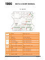
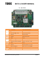
The ML-2012/13 is equipped with 4 and the ML-215/315 with 2 digital inputs. These inputs are interruptinterrupt
driven what means that they activate the data logger to wake up when sleeping, and that a signal-change
signal
on the input is never missed. So, these inputs are ideal to use for counting events (like the pulses from an
energy-meter or a rain gage),, or to set an Alarm state (e.g. level or float switch).
switch). The signal level needs to
be zero volts and 3.6 volts (“0”level and “1” level). The inputs are “5 Volts tolerant” So standard 5 Volts
signals are also OK. Any other voltage
voltage needs to be adapted to the right range, before connecting. The
user can select whether the input has to be “pull-up”
“pull
or “pull down”
4.7.1
Pull up type
The pull up type of input means that there is an internal resistor mounted between the input and the Vcc
Power supply. So, when NO signal is connected, the input will be logical high. This type of inputs is very
convenient for use with “open collector” systems or “NPN outputs”
4.7.2
Pull down type
The pull up type of input means that there is an internal resistor mounted
mounted between the input and the
ground. So, when NO signal is connected, the input will be logical low. This type of inputs is very
convenient for use with “active output” systems or “PNP outputs”
4.8
Coil input
Input #4 (ML-2012/13 only) is a special digital
digital input. It is a so called “coil input”. This is a very sensitive
digital input. From point of functionality, the input is exact the same as the other inputs, but electrically
there are differences.
While the normal digital ports use the 0, 5 Volts levels
levels (or 0, 3.6 Volts) the coil input uses very low signal
levels, of only a couple of millivolts. This input is used for devices with this “energy less” system.
Attention: The coil input of the ML2012/13 is so sensitive that a short piece of unconnected wire is
enough to let the ML-2012/13
2012/13 “pick up” signals from the environment. Be aware of this, and use a
shielded cable. The reception of RF-signals
RF signals can lead to problems with the performance of the system.
The coil-input
input can demand very much processing power,
power, in case of reception of RF-signals.
RF
The coil input is very convenient when used with water meters with a passive coil output.
Manufacturers of low power instruments
page 26