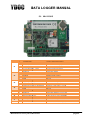
1
DATA LOGGER MANUAL
Type ML-2012/2013/215/315
ML 2012/2013/215/315
Low power 2G/3G data loggers
logger
Title
:
User Manual ML-2012/
2012/2013/215/315
Version
:
1.6
Manufacturers of low power instruments
Date
:
2
25-Aug-2015
page 1
DATA LOGGER MANUAL
WARNING
THE FOLLOWING OPERATING INSTRUCTIONS ARE FOR USE BY QUALIFIED
PERSONNEL ONLY. TO AVOID DAMAGE OR MALFUNCTION, DO NOT PERFORM
ANY OPERATING OTHER THAN THAT CONTAINED IN THIS MANUAL. ANY
OPERATOR SHOULD BE SKILLED WITH A TECHNCAL BACKGROUND BEFORE
OPERATING THE DEVICE.
PREFACE
Congratulations!
With your purchase of an YDOC Low Power data logger with mobile network capabilities.
apabilities.
This manual describes the operation and (hardware) installation of the ML-2012/20
ML
2013/215/315 Data
logger.
The chapter Getting Started briefly describes the data logger, prepares you to install it, and tells you how
to put it into operation.
The Chapter Operating Basics covers basic principles of operation of the data logger. The operating
interface (menu) and the tutorial examples, rapidly
rapidly help you to understand how your data logger operates.
The Chapter Reference teaches you how to perform specific tasks and provides a complete list of
operating tasks and useful background information.
The Appendices provide a list with all available options, and other useful information.
We recommend you to read this manual carefully before installation of the data logger.
logger
Warranty
All YDOC instruments are warranted for 3 years against defective materials and workmanship. Any
questions with respect
ect to the warranty mentioned above should be taken up with your YDOC Distributor.
Manufacturers of low power instruments
page 2
DATA LOGGER MANUAL
Table of Contents
WARNING ................................................................
................................................................................................
.................................................... 2
PREFACE ................................................................
................................................................................................
..................................................... 2
1 Product Description ................................................................................................
................................
............................................................... 6
1.1
Models and Editions ................................................................................................
................................
..................................................... 7
1.1.1 ML-2012 ................................................................................................
................................
.................................................................... 8
1.1.2 ML-2013 ................................................................................................
................................
.................................................................... 8
1.1.3 ML-215/315 ................................................................................................
................................
............................................................... 9
2 Getting started ................................................................................................................................
................................
..................................... 10
2.1
Vibration ................................................................................................................................
................................
...................................... 10
2.1.1 Do’s and Don’ts ................................................................................................
................................
...................................................... 10
2.2
Inserting the SIM-card ................................................................................................
................................................ 10
2.3
Power on for the First time................................................................................................
time
.......................................... 11
2.4
Connect to a PC ................................................................................................
................................
......................................................... 11
3 Operating Basics ................................................................................................
................................
................................................................. 12
3.1
Configuration menu ................................................................................................
................................
.................................................... 12
4 Reference ................................................................................................................................
................................
............................................ 18
4.1
Principle of Operation ................................................................................................
................................
................................................. 18
4.1.1 Sample interval ................................................................................................
................................
....................................................... 18
4.1.2 Data logging interval ................................................................................................
............................................... 18
4.1.3 Send Interval ................................................................................................
................................
........................................................... 18
4.1.4 Example ................................................................................................
................................
.................................................................. 18
4.2
SDI-12 ................................................................................................................................
................................
......................................... 19
4.2.1 SDI-12 Hardware ................................................................................................
................................
.................................................... 19
4.2.2 SDI-12 Wiring ................................................................................................
................................
......................................................... 19
4.2.3 SDI-12
12 Baud Rate and Frame Format................................................................
.................................................... 20
4.3
RS232 ................................................................................................................................
................................
......................................... 20
4.4
RS485 ................................................................................................................................
................................
......................................... 21
4.5
Analog Inputs (4..20mA) ................................................................................................
............................................. 22
4.5.1 Loop Powered Devices ................................................................................................
........................................... 22
4.5.2 Potentiometer Input (MLx15-XXX
(MLx15
only) ................................................................
.................................................. 22
4.5.3 Analog Inputs (0 .. 10 V) ................................................................................................
......................................... 22
4.6
Analog Differential Inputs (ML-2013
(ML
only) ................................................................
.................................................. 23
4.6.1 Differential input ports theory of operation................................................................
.............................................. 23
4.6.2 Common mode noise rejection ................................................................
............................................................... 23
4.6.3 Using Load Cells With the ML-2013
ML
................................................................
....................................................... 23
4.6.4 Bridge of Wheatstone ................................................................................................
............................................. 23
4.6.5 Excitation Output. ................................................................................................
................................
................................................... 23
4.6.6 Analog Differential input 5................................................................................................
....................................... 25
4.6.7 Analog Differential input 6................................................................................................
....................................... 25
4.6.8 Calibration of Differential inputs ................................................................
.............................................................. 25
4.6.9 Overall Calibration ................................................................................................
................................
.................................................. 25
4.7
Digital inputs ................................................................................................
................................
............................................................... 26
4.7.1 Pull up type ................................................................................................
................................
............................................................. 26
4.7.2 Pull down type ................................................................................................
................................
........................................................ 26
4.8
Coil input ................................................................................................................................
................................
..................................... 26
4.9
Alarming ................................................................................................................................
................................
...................................... 27
4.9.1 Alarming - principal of operation ................................................................
............................................................. 27
4.10 Firmware Upgrade ................................................................................................
................................
...................................................... 28
4.10.1
When to use Firmware upgrades................................................................
upgrades
........................................................ 28
4.10.2
Firmware upgrade procedure ................................................................
............................................................. 28
4.10.3
Firmware upgrade over the air ................................................................
........................................................... 29
4.10.4
Firmware Driver limitations ................................................................
................................................................. 29
4.10.5
Power Switch Limitations ................................................................................................
.................................... 29
4.10.6
Modem ................................................................................................
................................
................................................................ 29
4.10.7
Modem Firmware
e Upgrade ................................................................
................................................................. 30
Manufacturers of low power instruments
page 3
DATA LOGGER MANUAL
4.11 SD-card ................................................................................................................................
................................
....................................... 30
4.11.1
Inserting an SD-card
card ................................................................................................
........................................... 30
4.12 Data Format ................................................................................................
................................
................................................................ 30
Header: ................................................................................................................................
................................
............................................ 30
Parameter Code: ................................................................................................
................................
............................................................. 31
Parameter Name: ................................................................................................
................................
............................................................ 31
Parameter Unit: ................................................................................................
................................
................................................................ 31
4.12.1
D-Records ................................................................................................
................................
........................................................... 31
Parameter Code: ................................................................................................
................................
............................................................. 31
Parameter value: ................................................................................................
................................
............................................................. 31
4.12.2
System-records ................................................................................................
................................
................................................... 32
System Message: ................................................................................................
................................
............................................................ 32
Additional System Message: ................................................................................................
........................................... 32
4.12.3
Data Modifiers ................................................................................................
................................
..................................................... 32
4.13 Transmission
mission of the data log file ................................................................
................................................................. 33
4.14 Input-drivers ................................................................................................
................................
................................................................ 33
4.14.1
Analog sensors ................................................................................................
................................
................................................... 33
4.14.2
Digital Pulse Sensor ................................................................................................
........................................... 34
Example
ple configuration Rain Measurement ................................................................
...................................................... 34
Counter ................................................................................................................................
................................
............................................ 35
Quantity................................................................................................................................
................................
............................................ 35
Rate ................................................................
................................................................................................
................................................. 35
4.15 Power supply ................................................................................................
................................
.............................................................. 36
4.15.1
Internal RTC backup battery ................................................................
............................................................... 36
4.15.2
Power consumption & Battery Life ................................................................
..................................................... 36
5 Pin configuration ................................................................................................
................................
.................................................................. 37
5.1
ML-2012 ................................................................................................................................
................................
...................................... 37
5.2
ML-2013 ................................................................................................................................
................................
...................................... 38
5.3
ML-215/315 ................................................................................................
................................
................................................................. 39
5.4
Pin description ................................................................................................
................................
............................................................ 40
5.4.1 Analog Inputs ................................................................................................
................................
.......................................................... 40
Analog Input 1 to 4 (ML-2012/13)
2012/13) or 1 to 2 (ML-x15AD/ADS/TFT)
(ML
................................
.................................................
40
Analog Input 3 to 4 (ML-x15AD/ADS/TFT
x15AD/ADS/TFT only) ................................................................
.............................................. 40
Analog Input 5 (ML-x15AD/ADS/TFT
x15AD/ADS/TFT only) ................................................................
..................................................... 40
Analog Input 5 to 8 (ML-2013
2013 only) ................................................................
................................................................. 40
5.4.2 RS 485 A & B ................................................................................................
................................
.......................................................... 40
5.4.3 Power Switch ................................................................................................
................................
.......................................................... 40
5.4.4 VBAT + ................................................................................................................................
................................
................................... 40
5.4.5 RX & TX COM 1 & Com 3 ................................................................................................
...................................... 40
5.4.6 SDI-12 Hi ................................................................................................
................................
................................................................ 40
5.4.7 Digital inputs ................................................................................................
................................
........................................................... 41
5.4.8 +3V6 ................................................................................................................................
................................
....................................... 41
5.4.9 Antenna placement and field strength ................................................................
.................................................... 41
6 Maintenance and Repair ................................................................................................
................................
..................................................... 41
6.1
RTC Lithium Battery replacement ................................................................
.............................................................. 42
6.2
Recalibration ................................................................................................
................................
............................................................... 42
6.3
XRAY ................................................................................................................................
................................
.......................................... 42
7 Safety ................................................................
................................................................................................
.................................................. 42
7.1
Power supply ................................................................................................
................................
.............................................................. 42
7.2
ESD................................................................................................................................
................................
............................................. 42
8 Environment and disposal ................................................................................................
................................
................................................... 43
9 Transport and Storage ................................................................................................
................................
........................................................ 43
10
Specifications ................................................................................................................................
................................
................................... 44
11
EU Declaration of Conformity ................................................................................................
.......................................... 45
11.1 ML-2012 ................................................................................................................................
................................
...................................... 45
11.2 ML-2013 ................................................................................................................................
................................
...................................... 46
11.3 ML-x15 ................................................................................................................................
................................
........................................ 47
Manufacturers of low power instruments
page 4
DATA LOGGER MANUAL
12
13
Supported serial sensor devices................................................................................................
devices
...................................... 48
Trouble shooting ................................................................................................
................................
.............................................................. 49
Manufacturers of low power instruments
page 5
DATA LOGGER MANUAL
1
Product Description
d
is logged onto the
The data logger is designed to retrieve, and store data from various sensors. This data
embedded SD-card.. Also the stored data can be send from the data logger to any remote computer you
like. To use this feature, you need a valid SIM-card.
SIM card. Contact your local telecommunications supplier for
more information on the SIM card
ard you will need. The unit accepts various power sources, selectable by
the different version types. The user should connect his sensor(s) of preference to the connector board of
the device. Captured data can be stored, send, visualized and manipulated in many ways.
The data logger is a small, ultra low power, high-end
high
data logger with built-in 2G/3G cellular-modem.
cellular
This
small data logger, is further provided with an internal temperature sensor, 2 GB micro SD-card and an
SIM card slot. The logger can be powered
powered by an internal 3.6 Volt Lithium battery that will last for years
when the logger is configured in a low-power
low
mode.
inputs The
The ML-2012 2G data logger can acquire physical signals by 4 current loop inputs, 4 digital inputs.
ML-2013 2G data logger can acquire physical signals by 4 current loop inputs, 4 digital inputs and 2 hires
amplified differential voltage inputs, which can be used to connect pyranometers or in combination with a
stable excitation voltage to connect “Wheatstone resistive
resistive bridge sensors” like load cells. The ML-215
(2G) and ML-315 (3G) data logger can acquire physical signals by 2 current loop inputs,
inputs 2 voltage inputs,
1 resistance input and 2 digital inputs.
The data logger is provided with generic serial port drivers
drivers to capture measurements from ASCII,
MODBUS/RTU, NMEA or SDI-12
12 sensors, custom drivers can be developed
ed on request. External sensors
can be powered by the data logger itself, to prevent them to consume power while the data logger is a
sleep. The excitation
on voltage is switched off during sleep as well.
Its key features are;
-
A maximum sample rate of 4 Hz,
Recording length up to 2 GB,
Four channel 12 bits A/D inputs
One resistance input (ML
ML-215/315 only)
2 digital inputs (ML215/315
ML215/315)
4 digital inputs (ML-2012/13
2012/13)
Two channels 16 bits differential A/D convertor for low voltage measurements (ML-2013
(
only),
Internal micro SD-card with standard FAT-32
FAT 32 File system for easy use with a PC,
Easy configuration by menu’s of embedded menu,
Can be used with Windows XP,
XP Vista and W7
Low power / long Battery life (see specification sheet),
Embedded 2G/3G modem for remote operation,
Alarming by SMS and data delivery by e-Mail,
e
FTP or TCP
Internal voltage convertor for supplying 12 VDC power to the connected sensor(s),
Stable
table excitation voltage to power Wheatstone bridged sensors (ML-2013
(
2013 only),
only
Firmware upgrade over the air for adding new features to your device.
Remote configuration over the air, for adjusting your configuration from remote.
Manufacturers of low power instruments
page 6
DATA LOGGER MANUAL
1.1
Models and Editions
The following models and editions are available:
Code
ML-2012
ML-2013
ML-2013-PV
ML-2013-DC
ML-215ADS-LI
ML-315ADS-LI
ML-x15DS-LI
ML-x15AD-LI
ML-x15TFT
ML-x15xxx-PV
ML-x15xxx-DC
Description
Lithium powered 2G data logger in IP65 ABS
enclosure with external antenna.
Lithium powered 2G data logger in IP67
enclosure with integrated antenna.
As ML-2013,
2013, but with NiMH AA solar charger
integrated in cover.
As ML-2013,
2013, but with 8 .. 30V DC-adapter
DC
and
NiMH AA charger integrated in cover.
Lithium powered 2G data logger in IP67
enclosure with internal antenna.
Lithium powered 3G data logger in IP67
enclosure with internal antenna.
As ML-x15ADS
x15ADS-LI but without analog inputs
As ML-x15ADS
x15ADS-LI but without serial port
As ML-x15ADS
x15ADS but with 3.5” color TFT
ML-x15xxx with NiMH AA solar charger
integrated in cover.
ML-x15xxx with 8 .. 30V DC-adapter
DC
and NiMH
AA charger integrated in cover.
Remarks
Lithium battery not included.
Lithium battery not included.
NiMH AA batteries not included.
To connect the logger to an
external VDC source.
Lithium battery not included.
Lithium battery not included.
DC powered with backup battery
NiMH AA batteries not included.
To connect the logger to an
external VDC source.
The data logger will be supplied without pre-mounted
mounted cable glands, giving the user the freedom to choose
the number and
nd size of the glands them self to avoid water We recommend removing the PCB before
drilling.
Manufacturers of low power instruments
page 7
DATA LOGGER MANUAL
1.1.1
ML-2012
The IP65 ABS enclosure of the ML-2012
ML
has a small form factor very suitable
e to be integrated inside an
existing cabinet or the bucket of a rain gauge.
1)
2)
3)
4)
5)
SDI-12 and power switch
Analog inputs
Digital inputs
RS232 connector
RS485 connector
1.1.2
ML-2013
The waterproof IP67 enclosure of the ML-2013
ML
exists out of a casing and cover of glass fiber reinforced
polyamide (PA66/GF20) with in between a silicon gasket. The ML-2013
ML 2013 can be used outdoors.
1) Analog inputs
2) RS232 connector
3) Excitation DC/DC convertor
4) Digital inputs
5) SDI-12,
12, power switch and
Excitation
on connector
6) RS485 connector
7) Power switch DC/DC convertor
8) RTC clock battery
9) Power supply connector (to cover
)
10) Fuse
11) Processor
12) Antenna Connector
13) Quad Band Modem
14) USB Connector
Manufacturers of low power instruments
page 8
DATA LOGGER MANUAL
15) SIM (2FF) & SD-card Holder
1.1.3
ML-215/315
The waterproof IP67 enclosure of the ML-2013
ML
exists out of a casing of polycarbonates and a cover of
glass fiber reinforced polyamide (PA66/GF20) with in between a silicon gasket. The ML-215/315
ML
can be
used outdoors.
1) Analog inputs
2) RS232/RS-485/SDI-12 connector
3) Digital inputs
4) 12V Power switch and alarm output
5) Accessory port (TFT, CAM, BT4.0, etc.)
6) 2G (ML-215) or 3G (ML-315)
315) MODEM
7) Internal/External antenna selection jumper
8) U.FL connector for external antenna
9) Internal antenna
10) Connector for optional external waterproof USB connector
11) Internal USB connector
12) Processor
13) SIM (2FF) & SD-card Holder
14) Fuse
15) 3V6 power supply connector (to PV or DC cover)
16) D-Size
ze 3.7V Lithium battery holder (ML-x15xxx-LI
(ML
only)
17) RTC clock battery
Manufacturers of low power instruments
page 9
DATA LOGGER MANUAL
2
Getting started
2.1
Vibration
At all times the data logger must be protected against vibrations. These vibrations can harm the
performance of the data logger. Especially the real time
time clock can be harmed by long-lasting
long
vibrations
2.1.1
Do’s and Don’ts
Do’s
Always provide a dry and clean environment when you open the case of a data logger,
logger
When you open the case, use a Philips screwdriver of 2mm for loosening the screws,
Protect the data logger against mechanical stress and vibrations
Don’ts
-
2.2
Don’t try to use a plain screwdriver for loosening the screws, you will damage the screws,
Avoid touching the PCB directly.
Inserting the SIM-card
card
The wireless data functions will only work when
when an activated SIM, with a valid subscription is placed in the
data logger.. In the menu the configuration and network settings must also mach to those supplied by the
SIM card provider. The pin code of the SIM card must be removed prior to insertion in the
t data logger. To
prevent problems with the SIM card it can be inserted in a mobile phone or 2G/3G data modem. In a
Mobile phone or 2G/3G modem the 2G/3G,, SMS and GSM data functionality can be tested.
When you have obtained a 2FF SIM-card,
SIM
you can insert it into the SIM-card-holder.
holder.
Beware:
•
•
•
•
•
•
•
•
•
Remove the PIN code (this can be done with the use of a mobile
phone),
Check the settings of your mobile provider,
Check the settings for communicating via FTP / Email / Native TCP,
Check the capability of data communication for your service-provider,
service
Make sure the SIM-card
card is installed correctly, and not upside down.
The Oblique side of the card should be visible. (see picture).
Installation of the SIM card needs to be done in a clean and dry
environment.
Avoid contact with the electronic parts around the SIM card.
Remove power before changing or inserting a SIM card.
The same applies to the SD--card.
Manufacturers of low power instruments
page 10
DATA LOGGER MANUAL
ESD Attention: Although the data logger is designed to withstand certain amounts of electrostatic
discharge, itt is advised to avoid discharged risks. Especially when the housing is open and the electronic
parts are exposed. Please do not touch the PCB if you don’t have to. It is strongly recommended to use
an earthed wrist-band
band when touching the PCB.
The data logger
gger must be handled with care and never exposed to ESD discharges. When installing a
sensor or other wiring, make sure there is no power on both devices. ESD discharges could cause
invisible damage. This endangers long term stability and proper operation.
2.3
Power on for the First time
In the factory the data logger is programmed with the necessary system information. This information is
viewable in the menu. The data logger is ready to use out of the box if the preparations are checked.
•
•
•
•
SIM card is inserted,
SD-card is inserted,
Internal battery, or mains power is connected
Antenna is connected.
Next, connect your sensors, please consult your sensor’s manual for wiring.
2.4
Connect to a PC
OS compatibility: The data logger can be connected to any PC with USB 2.0 running on Microsoft
Windows XP, Windows Vista or Windows 7
Installation procedure for the internal USB adapter for Windows XP is given on the CD.
Manufacturers of low power instruments
page 11
DATA LOGGER MANUAL
3
Operating Basics
3.1
Configuration menu
The data logger can be configured by means of terminal emulation software like ‘hyper terminal’. Our own
terminal emulation software ‘YDOC-terminal’
‘YDOC
can be downloaded from www.your-data-our-care.com
www.your
The menu is comprehensive and easy to use. For each different sensor the same approach is used.
Below, one example is given to fully understand the operation of the menu. The example takes you
through a configuration from start to final stage. Only a few menu-items
menu items are used in this example,
exa
for a
complete overview of all menu-items,
items, see chapter Reference. All menu items use the same approach
which is explained in this example. This example explains only the configuration of the firmware, NOT the
wiring. For wiring information see the reference.
re
Example:
3 for operation with the following:
Let’s Configure a ML-2013
-
Analog pressure transmitter 4 .. 20mA
CT2X conductivity / temperature sensor (INW)
FTP data output
EMAIL data output
Connect the logger to a free USB port on your computer and
and open with a terminal emulator the virtual
COM-port
port (e.g. COM7) as assigned by Windows to the logger. The first time Windows will ask (if not
already installed) for an USB-driver,
driver, which can be downloaded from our website as well.
When the terminal emulator
tor has opened the COM-port,
COM
press:
<Ctrl>A<Shift>M<Ctrl>D to enter the configuration menu.
You’ll see a screen similar to this:
Running
Configuration Menu ML-2013
2013 Logger Version 1.6 Build 1
[0]
[1]
[2]
[3]
[4]
[5]
>
Run
Date & Time
>> 2013/07/05 12:58:21
System Information
>> 3002389
Configuration Setup >> Brasil
Configuration Review
Maintenance
First we like to give this data logger appropriate identification codes.
So, press 3 <Configuration Setup>
Manufacturers of low power instruments
page 12
DATA LOGGER MANUAL
You’ll see this screen:
First Rename your Device by
Selecting option 1
(General Settings)
Configuration Setup
[0]
[1]
[2]
[3]
[4]
[5]
[6]
[7]
[8]
[9]
[A]
[B]
[C]
[D]
[E]
>
Exit
General settings
Modem settings
NTP Time update
Alarm SMS
SMS Commands
Internal sensors
Analog sensors
Digital sensor
GSM signal sensor
Serial port 1
Serial port 2
FTP output
TCP output
Email output
>> YDOC
>>
>>
>>
>>
>>
>>
>>
>>
>>
>>
>>
>>
Not
Not
Not
Not
Not
Not
Not
Not
Not
Not
Not
Not
Used
Used
Used
Used
Used
Used
Used
Used
Used
Used
Used
Used
After selecting “General Settings” the screen will look like this:
General settings
[0]
[1]
[2]
[3]
[4]
[5]
[T]
>
Exit
System Name
>> YDOC
Data logging interval
>> Normal 00:01:00; Alarm Not Used
Direct Data output on Data Alarm >> Off
Deployment date and time
>> 2013/07/05
201
20:17:42
Time zone
>> 2
SD-card test
> Passed
>>
< General settings>
1. Press 1 and enter the name of your preference
2. Choose your data logging interval. We used 10 minutes, and NO Alarming.
3. Enter the deployment date & time. This can be a time in the future when logger should start working.
We will use the actual date & time to start right away.
4. Exit and save changes.
5. Now, the overall configuration is setup and we proceed with the configuration of the sensors and data
output.
Next type 7 for Analog sensors
Analog sensors
[0]
[1]
[2]
[3]
[4]
[5]
[6]
[T]
>
Exit
Port 1
Port 2
Port 3
Port 4
Port 5
Port 4
Analog
(mA)
(mA)
(mA)
(mA)
(mV)
(mV)
input test
>>
>>
>>
>>
>>
>>
>>
Not Used
Not Used
Not Used
Not Used
Not Used
Not Used
Passed
Choose 1 for Port 1 (mA) and the next screen will appear:
Manufacturers of low power instruments
page 13
DATA LOGGER MANUAL
Analog sensor
[0]
[1]
[2]
[3]
[4]
[5]
[6]
[7]
[8]
[9]
Exit
Name
>> Analog
Sensor power switch
>> Disabled
Sample interval
>> Normal 00:00:01; Alarm Not Used
Port mode
>> 4-20 mA
Parameter
>> Analog 1
Parameter value at 4mA
>> 0 units
Parameter value at 20mA
>> 100 units
Determine linear conversion function (2 calibration points)
Determine
termine linear offset only (1 calibration point)
[R] Remove
>
1. Assign a name to the sensor (option 1: Name)
2. Set the power switch to enabled and enter the warm-up
warm up time. (the power switch will supply the sensor
with 12 Volts, and will be activated the time you specify, before a measurement is taken)
3. Set the sample interval. We use 10 seconds, to quickly check the sensor’s operation. A high range
sample interval is no problem for the battery-life,
battery life, because the sensor will sleep until its data logging
interval is reached. So don’t be modest with the sample interval. It gives you great comfort.
4. Set the parameter name.
5. Set both minimum (option 6) and maximum (option 7) values of your sensor at 4mA and at 20mA. If
you don’t know those values you could determine the
the scaling by measuring two calibration points
(option 8). Those calibration points don’t have to be at the sensors absolute minimum and maximum,
but just two different points within the range of the sensor. (e.g. a measurement at 1m water level and
a measurement
urement at 2m water level, while the sensors range is 0..10m)
6. If necessary option 9 can be used to perform an offset correction by measuring a single calibration
point.
7. Save and Exit
Your screen will look similar to the one underneath:
Analog sensor
[0]
[1]
[2]
[3]
[4]
[5]
[6]
[7]
[8]
[9]
Exit
Name
>> Upperstream
Sensor power switch
>> Enabled; Warm up time 00:00:01
00:00:
Sample interval
>> Normal 00:00:10;
00:00: ; Alarm Not Used
Port mode
>> 4-20
4
mA
Parameter
>> Water level
Parameter value at 4mA
>> 0 m
Parameter value at 20mA
>> 10 m
Determine linear conversion function (2 calibration points)
Determine linear offset only (1 calibration point)
[R] Remove
>
Manufacturers of low power instruments
page 14
DATA LOGGER MANUAL
Now we add the CT2X to the system:
Go to menu-option
option A <serial port 1> => RS 485 sensors
RS485 Sensors
[0]
[1]
[2]
[3]
[4]
[5]
[6]
[7]
[8]
>
Choose the INW CT2X (option 2)
Exit
Generic MODBUS/R
RTU
INW CT2X
INW DO
INW PT2X type A
INW PT2X type B
INW PT12
INW TempHion
OMC506
Your
ur screen should look like this:
INW CT2X sensor
[0]
[1]
[2]
[3]
[4]
[5]
[6]
[7]
[8]
[9]
Exit
Name
Port settings
Sensor power switch
Sample interval
Temperature
Pressure
Conductivity
Conductivity nLF
Salinity
>>
>>
>>
>>
>>
>>
>>
>>
>>
INW CT2X
Port 1; 38400 Baud; RS485; Address 1
Disabled
Normal 00:00:10; Alarm Not Used
Temperature
Pressure
Not Used
Not Used
Not Used
[R] Remove
>
Multiple CT2X sensors can be connected to an RS485 bus so you need to specify its address (assuming
1 in this example). This sensor is a multiple parameter sensor, so please specify which you want to log.
Attention:
Because this is a digital sensor, it takes a little bit more time to measure than an analog sensor. So don’t
set the sample interval of digital sensors too short. 1 second is possible, but probably not ¼ sec. Just to
be sure we choose 10 sec. Consult the manual of your digital sensor and check the response time. The
sample-interval
interval must be larger than the response time of the sensor.
Now your sensors are added to the configuration of the ML-2012/13.
ML
Manufacturers of low power instruments
page 15
DATA LOGGER MANUAL
Next thing is the setup of the data outputs.
Before that, we have to configure the general modem settings
settings for GPRS operation. Consult your GPRSGPRS
provider for the correct local settings. In the reference, a table is included with some international GPRSGPRS
providers and their settings. These settings might have been changed.
Go to Menu-option
option 2 <Modem settings>
Modem settings
[0]
[1]
[2]
[3]
[4]
[5]
[6]
[7]
[S]
[T]
>
Exit
Modem during sleep
Frequency selection
Provider selection
APN Acces point
APN User name
APN Password
Dial-in
in Autorisation
GSM Signal strength
APN Login test
>> Off
>>
>>
>>
>>
>>
>>
internet
kpn
kpn
Off
Passed
Not Done
Now we can setup the FTP,, TCP and Email output
Therefore go to menu-option:
-C
Ftp Output.
-D
Tcp output
-E
Email output
Enter your server-settings.
It should look like this:
Email settings
[0]
[1]
[2]
[3]
[4]
[5]
[6]
[7]
[8]
[9]
[A]
[R]
[T]
>
Exit
Name
Send interval
Send delay
SMTP Server
SMTP Port
User name
Password
Originator address
Destination address
Subject
Remove
EMAIL test
>>
>>
>>
>>
>>
>>
>>
>>
>>
>>
Email
Normal 01:00:00; Alarm Not Used
Not Used
smtp.
smtp.provider.com
25
reh6a01
********
r.kleine@
[email protected]
[email protected]
YDOC upperstream
Beware:
Some providers
strictly check the
Originator
address. So
make sure this
address is valid.
>> Not Done
Now perform an Email test and check if it is working right.
It is strongly recommended to include some internal sensors in the configuration, because of the
monitoring
onitoring of the performance of the data logger itself. Most users like to keep track of the battery-life
battery
for
example.
Manufacturers of low power instruments
page 16
DATA LOGGER MANUAL
Go To menu-option
option 6 <internal sensors>
Internal sensors
[0]
[1]
[2]
[3]
[4]
[5]
[6]
[7]
[8]
[9]
[A]
[B]
[C]
[D]
[E]
[F]
Exit
Name
Sample interval
Battery Capacity (mAh)
Battery replaced
Rest Capacity
Rest Power
Processor Temperature
Voltage
Current
Max Current
Min Current
Average Current
Free Disk Space
Operating Cycle
Free Disk Space
>>
>>
>>
>>
>>
>>
>>
>>
>>
>>
>>
>>
>>
>>
>>
Internal
Normal 00:00:01; Alarm Not Used
17000
Yes
Rest Capacity
Not Used
Processor Temperature
T
Voltage
Not Used
Not Used
Not Used
Not Used
Not Used
Not Used
Not Used
[R] Remove
>
A sample interval of 1 second is fine. All internal sensors are very fast.
Set the “Battery Replaced” to “Yes”, only when you installed a new battery.
Select the items you like to be informed about.
See the reference for a complete description of the items.
Now your data logger is configured and ready to use.
To check your wiring and sensors, you can evaluate the actual values.
To see them press: <Ctrl>A<Shift>V<Ctrl>D
The result should be like this:
13/07/05 14:22:04 Actual Values ML-2012/13 Logger Version 1.6 Build 1
AIN1
Waterlevel
-25
25
meters MSL
TMP
Temperature
20.2
C
PRS
Pressure
0
0.2
psi
RCi
Rest Capacity
100
%
PTi
Processor Temperature
57.4
C
Vi
Voltage
3.6
V
Ci
Current
82
mA
Manufacturers of low power instruments
page 17
DATA LOGGER MANUAL
4
Reference
4.1
Principle of Operation
Your YDOC data
ata logger is capable of collecting and storing data of multiple sensors. To accomplish this,
many tasks are performed. These “tasks” are scheduled and executed on their specified time. The timing
of this process is very important and is determined by the internal scheduler. This scheduler keeps track
of all the internal states of the various tasks and assigns processor time to the
the different tasks. Each task
is executed on its own interval. To understand more about this, Fist we explain the different intervals.
There are three different intervals:
1) Sample Interval
2) Data Log Interval
3) Send Interval
4.1.1
Sample interval
The sample interval is the interval on which a sample from the sensor is taken (expected). So,
measurements from sensors are done at the sample interval. The sample interval is valid ONLY when the
device is in the active state. When the data logger is in sleep-mode,
s
mode, the tasks, triggered by the sample
interval will NOT execute.
4.1.2
Data logging interval
This interval determines when a data value, obtained by the sample interval-task,
interval task, is stored onto the SDcard.. This type of interval is ALWAYS valid. So, even when
when the data logger is in sleep-mode,
sleep
it will wake
up when the Data logging Interval has reached its count.
4.1.3
Send Interval
The send interval determines the interval on which data is send, via the internal modem. This interval is
ALWAYS valid, even if the data logger is in sleep-mode.
sleep
4.1.4
Example
Let’s evaluate the following settings of the data logger:
-
Sample Interval: 5 seconds
Data Log Interval: 10 minutes
Send Interval: 3 hours
When the configuration is ready and the user disconnects the USB-Cable;
USB
1. Data logger is switched into sleep-mode,
sleep mode, and current draw is reduced to a minimum level.
2. The Sample interval of 5 seconds is discarded, because this interval is only active when the data
logger is NOT in sleep-mode.
mode. So nothing happens until the Data Log interval
interva has reached his count.
(So this happens on 0, 10, 20, 30, 40, 50 minutes every hour)
3. When the Data Log Interval count has reached his count, the data logger will awake from the sleep
mode, and will take a sample and stores the data on the SD-card. When the
he sample is taken, the data
Manufacturers of low power instruments
page 18
DATA LOGGER MANUAL
logger goes into sleep-mode
mode again. This is repeated, until the time has matched the Send interval.
So, in this example, this is 3 hours.
4. When Data Send interval is reached, the data logger will wake-up,
wake up, and starts to send the previously
p
collected data (stored on the SD-card)) to the server. So, in this example, every 10 minutes a sample
is taken, and every 3 hours, 18 samples are send.
Note: So, the data logger does not perform any averaging. Even if the sample interval is much faster than
the data log interval, only one sample is stored.
The use of the sample interval is for evaluating proper behavior of the system, while the USB is
connected. Because in that case, the sample interval is valid, and the user can observe the value’s
value
obtained from the sensor in real time. In this case, the user can evaluate these values every 5 seconds.
4.2
SDI-12
The ML-2012/13 is provided with an SDI-12 port. This port is connected to port 2 and is shared with the
normal RS232 operation. This means that
that the user has to select whether he wants to use RS232 or SDI12.
12 port as well, but it is shared with the
The ML-215/315 (except the ML--x15AD) is provided with and SDI-12
RS-232 and RS-485 port.
When SDI-12
12 is selected, it acts like a SDI-12
SDI
recorder and its specific SDI-12
12 commands are embedded
in the driver of the input-sensor.
sensor. So the user can easily select his sensor and specify its SDI-12-adress.
SDI
For more information see the description of you SDI-12
SDI
sensor.
4.2.1
SDI-12 Hardware
The SDI-12 standard is a very commonly used interface-standard
interface standard in the USA. In Europe, it is rarely used.
The signal levels are quite different from those of RS232 and RS485. So, you cannot connect a SDI-12
SDI
sensor to a RS232 or RS485 port, it won’t work. The use of convertors between
between RS232/485 and SDI-12
SDI
is
discouraged, because of the high pricing of the convertors and the bad performance (see note).
4.2.2
SDI-12 Wiring
The SDI-12
12 electrical interface uses the SDI-12
SDI 12 bus to transmit serial data between SDI-12
SDI
data recorders and sensors. The SDI-12
SDI 12 bus is the cable that connects multiple SDI-12
SDI
devices.
This is a cable with three conductors:
1) a serial data line, 2) a ground line and 3) a 12VDC line
Manufacturers of low power instruments
page 19
DATA LOGGER MANUAL
The wiring length between a sensor and the data-recorder
data recorder must not exceed 60 meters. The maximum
number of sensor connected to a SDI-12
SDI
bus is limited to 10. The data logger is protected against
transients on the SDI-12 bus.
4.2.3
SDI-12
12 Baud Rate and Frame Format
Forma
The baud rate for SDI-12
12 is 1200. Frame format is as follows:
1 start bit
7 data bits, least significant bit transmitted first
1 parity bit, even parity
1 stop bit
Note:
SDI-12 is a half-duplex
duplex protocol, so the data-recorder
data
has to switch between transmitting
ransmitting and receiving. A
convertor from RS232 SDI-12,
12, must perform this task. However, it is not aware of the exact timing of
the protocol. Therefore it uses fixed (or configurable) delays to switch between Tx and Rx. After each byte
send by the convertor, it waits, during the fixed delay, for another character, and if it doesn’t arrive, it
switches to Rx. The intelligence needed to perform these tasks is mostly done by a microcontroller inside
the convertor, that’s
hat’s the main reason for its high pricing. This method is doing the job for most cases, but
it is not as good as a real SDI-12
12 port. The real SDI-12
SDI 12 port is aware of the exact protocol-timings
protocol
and
after the last character it switches to RX-mode
RX
immediately,
y, without the delay. Therefore no replies are
missing. Your YDOC data logger has a true SDI-12 port.
For more information on the SDI--12 protocol: see www.sdi-12.org
4.3
RS232
Your ML-2012/13
2012/13 comes with 2 RS232 ports, capable of baud rates of up to 115200 bps (230400
(2
bps on
request). The ports are: port 1 and port 2. Port one is shared with the RS-485 port and port 2 is shared
with the SDI-12 port. The user can choose any combination he likes, as long as he is
i using only one at a
time. (e.g. you cannot share RS232
RS23 and RS485 one the same port).. If a user needs RS232 and RS485
simultaneously, he needs to setup Port 2 also.
Manufacturers of low power instruments
page 20
DATA LOGGER MANUAL
The ML-215/315 (except the ML--x15AD) comes with one RS-232
232 port, which is shared with SDI-12
SDI
or
RS-485
RS232 is a widely spread interface standard,
standard, which uses 3 wires (minimum) for data communication. It is
a so called asymmetric interface, that uses one wire for Tx, one for Rx and one for ground. It is called
asymmetrical, because it uses only one wire per signal. Therefore it’s susceptible for
fo interference, and
hence, the maximum cable length is limited to 15meters.
Please keep in mind these limitation when you design your system.
RS232 is not a bus system, and therefore it is only allowed for one device to be connected to a RS232
port. So, the maximum number of serial devices to connect to your ML-2012/13
2012/13 is 2. RS232 sensors
should be connected to the data logger with their signals crossed. That is Rx Tx.
We strongly recommend using RS485 instead of RS232, when cable length exceeds the 15m.
1
4.4
RS485
RS485 is a serial bus-system,
system, which uses 3 wires for its communication. It uses a “differential balanced
line”, which can span relatively
tively large distances (up to 4000 feet (1200
(1
m)). A rule of thumb is that the
8
speed in bit/s multiplied by the length
ength in meters should not exceed 10 . Thus a 50 meter cable should not
signal faster than 2 Mbit/s.
Instead of RS232, RS485 is capable of communicating with more than one device. After all, it is a busbus
system.
RS485 sensors are called “slaves” and must have their unique address. The data logger acts as a master
and retrieves the information from the slaves. Only one slave can respond to the requests of the master
at a time.
To set up your RS485 sensor for use with the data logger,, make sure that the address is programmed
correctly, and that the sensor address is unique.
Figure 1: RS485 Wiring
RS485 is often used with MODBUS/RTU-sensors,
MODBUS/RTU
and is less
ss susceptible for Electrical interference than
RS232.
Your ML-2012/13
2012/13 has one RS485 port which is capable of driving multiple sensors (maximum amount of
sensors depends on specs from the manufacturer of the sensor, a practical figure is 10. The maximum
amount
mount of slaves, defined by EIA/RS485 is 32). For the exact number of sensors you can connect to your
ML-2012/13 see chapter Firmware Driver limitations
We recommend using twisted pair cable to connect to the sensors.
Manufacturers of low power instruments
page 21
DATA LOGGER MANUAL
4.5
Analog Inputs (4..20mA)
The ML-2012/13
2012/13 is equipped with four and the ML-215/315-ADS/TFT with two analog mA 12 bits ADAD
Conversion inputs. The input signal must be a 4..20 mA current loop. The impedance of the system is
150 ohms.
4.5.1
Loop Powered Devices
Some devices don’t need a power supply, but take their power from the current loop. But the primary
circuit of the data logger does NOT provide power for this. In this case, you need the power switch to
provide the energy for the current-loop.
current
Consult the manual of the loop-powered
powered device you like to
connect, and use the positive side of the power switch for the power supply. In most cases the data
logger is connected to a device with an active output signal, so there will be no problems connecting
co
it. If
you have questions about interfacing your device
devic with our data logger,, contact your YDOC-dealer.
YDOC
4.5.2
Potentiometer Input (MLx15-XXX
(MLx15
only)
The MLx15-XXX
XXX Models are equipped with a potentiometer input. This inputs acts as a voltage input, but
it uses passive sensors only. It is designed especially for potentiometers, like the ones in winddirection
meters and angle meters. This input is connected to the internal ADC directely and is translated into a 0
% - 100% value. The user has to connect the potentiometer between Vref and ground. The MLx15-xxx
MLx15
models has a Vref output for that. (Terminal X1.8) Because of the fact of the potentiometer is connected
between Vref an ground, the ADC value will always be the full range (0..4095) INDEPENDENT of
o the
value of the connected potentiometer. So, all types and all values of potentiometers are supported.
Although all values are supported,we strongly recommend to use high values only. This is because the
lower values are draining more power from the datalogger. Values between 100K and 4M7 are
recommended.
4.5.3
Analog Inputs (0 .. 10 V)
The MLx15-xxx is equipped with two analog 0 .. 10 V 12 bits AD-Conversion
Conversion inputs.
inputs The input signal
must be a dc signal which must not exceed 10 Volts.
Volts The user can adopt a higher voltage level if he uses
external resistors. This is done by a simple voltage divider. However this possibility offers a flexible way to
expand the range of the instrument, this is NOT covered in this manual, and the user may not seek for
supportt from YDOC on this topic.
Manufacturers of low power instruments
page 22
DATA LOGGER MANUAL
4.6
Analog Differential Inputs (ML-2013
(ML
only)
The ML-2013
2013 Data logger has, besides the four 12 bits analog current inputs, also two additional
Differential 16 bits voltage inputs. These inputs are very sensitive and particularly suitable for measuring
signals from load cells.
4.6.1
Differential input ports theory of operation
Differential inputs are very convenient for measuring differential or floating signals. The performance of a
differential input is much better than a normal, single
sing ended one, especially
specially with small mV signals.
Therefore, the differential inputs on the ML-2013
ML 2013 are very suitable for measuring load cells, pyranometers
and other low-level
level mV output sensors. A differential input consists of a negative (-)
( and a positive (+)
input. The voltage difference between these two inputs is the signal to be measured.
4.6.2
Common mode noise rejection
One of the major advantages over a single ended input is the common mode noise rejection. It “removes”
practically all noise that is present
nt on the input signal. Especially with long cables, noise is always present
on the leads. Since the input acts like a differential amplifier, the noise on the negative input is subtracted
from the noise on the positive input. What is left is the sensor-signal.
sensor
4.6.3
Using Load Cells With the ML-2013
ML
The ML2013 is very suitable for connecting load cells and other resistive elements. A load cell acts as a
bridge of Wheatstone and is a very sensitive and precise passive component.
4.6.4
Bridge of Wheatstone
The bridge of Wheatstone (the principle of operation of a load cell) is a circuit, consisting of 4 resistors.
Below a circuit is given:
Given, all R’s are the same the output voltage will be 0 Volts. In practice, one of the resistors is replaced
by a variable resistor
stor (often a strain gauge) . By varying the resistance of this resistor, the bridge will be
“unbalanced” and there will be an output Voltage, other than 0 Volts. To enable the circuit, the bridge has
to be powered by a very stable reverence Voltage, often called “Excitation Voltage”. The ML2013 has an
Excitation output for this purpose.
4.6.5
Excitation Output.
The ML-2013
2013 has an Excitation output for powering load cells, or other devices. It is a single output with a
fixed precision voltage output. This Excitation
Excitation output is driven by the Power Switch of the ML-2013.The
ML
default, fixed, Excitation Voltage is 5.000 Volts. For most load cells, this is OK. However, if the user
wishes another value, it can be selected by selecting 3 soldering jumpers on the bottom side
s
of the board.
Manufacturers of low power instruments
page 23
DATA LOGGER MANUAL
Here is how to set the jumpers for the correct Excitation Voltage:
Excitation Voltage Configuration
SJ1
SJ2
SJ3
Voltage
Open
Closed
Open
2.500 V
Closed
Open
Open
5.000 V
Open
Closed
Open
7.500 V
The default excitation is 5.000 V
Manufacturers of low power instruments
page 24
DATA LOGGER MANUAL
4.6.6
Analog Differential input 5
Analog input 5 is a Differential input with a build-in
build user selectable input-amplifier.
amplifier. Therefore channel 5
has a user selectable range. The user can set the range of the input according to his preferences. This is
done by adjusting the so called “port mode” The Ranges are given in the table underneath:
Input 5 ranges
Port mode
Voltage
0
0 .. 250mV
1
0 .. 500mV
3
0 .. 1000mV
4
0 .. 2000mV
4.6.7
Analog Differential input 6
Analog input 6 is the most sensitive differential input of the ML-2013.
2013. With exception of this sensitivity, the
channel is similar to channel 5.
Input 6 ranges
Port mode
Voltage
0
0 .. 10mV
1
0 .. 20mV
3
0 .. 40mV
4
0 .. 80mV
4.6.8
Calibration of Differential inputs
The Differential inputs are calibrated at the factory. This calibration is a so called 1 point zero offset
calibration. With this type of calibration, only the value at zero is adjusted. For input 5 this is very
accurate, it will be < 0.05 %. For an application that requires an even higher accuracy, the user can and
should do a user – overall calibration.
4.6.9
Overall Calibration
This type of calibration is offered to the user to get the most accurate readings possible. This type of
calibration is a two point’s calibration.
How it works:
The user can enter 2 pre-defined
defined data values into the ML2013. This is very convenient for i.e. Scales.
For example, the user has a standard load of 1 kg and one of 10 kg. He starts the calibration procedure,
and starts with the 1.0 kg load. The data logger,
logger, now, adapts the 1 kg and stores this value. Again with
the 10.0 kg load, it adjusts the scale to 10.0 kg and stores the settings. Now, the logger will calculate a
linear function between the two points. Note that all deviations in the sensor or the load
lo are compensated
from now on. With this type of calibration an accuracy of < 0.01 % is possible.
Note: for Channel six, with the enhanced pre-amplifier,
pre amplifier, this overall calibration is a must do. It is not
sufficient to only use the factory calibration. The factory calibration for this input is < 0.5%.
Manufacturers of low power instruments
page 25
DATA LOGGER MANUAL
4.7
Digital inputs
The ML-2012/13 is equipped with 4 and the ML-215/315 with 2 digital inputs. These inputs are interruptinterrupt
driven what means that they activate the data logger to wake up when sleeping, and that a signal-change
signal
on the input is never missed. So, these inputs are ideal to use for counting events (like the pulses from an
energy-meter or a rain gage),, or to set an Alarm state (e.g. level or float switch).
switch). The signal level needs to
be zero volts and 3.6 volts (“0”level and “1” level). The inputs are “5 Volts tolerant” So standard 5 Volts
signals are also OK. Any other voltage
voltage needs to be adapted to the right range, before connecting. The
user can select whether the input has to be “pull-up”
“pull
or “pull down”
4.7.1
Pull up type
The pull up type of input means that there is an internal resistor mounted between the input and the Vcc
Power supply. So, when NO signal is connected, the input will be logical high. This type of inputs is very
convenient for use with “open collector” systems or “NPN outputs”
4.7.2
Pull down type
The pull up type of input means that there is an internal resistor mounted
mounted between the input and the
ground. So, when NO signal is connected, the input will be logical low. This type of inputs is very
convenient for use with “active output” systems or “PNP outputs”
4.8
Coil input
Input #4 (ML-2012/13 only) is a special digital
digital input. It is a so called “coil input”. This is a very sensitive
digital input. From point of functionality, the input is exact the same as the other inputs, but electrically
there are differences.
While the normal digital ports use the 0, 5 Volts levels
levels (or 0, 3.6 Volts) the coil input uses very low signal
levels, of only a couple of millivolts. This input is used for devices with this “energy less” system.
Attention: The coil input of the ML2012/13 is so sensitive that a short piece of unconnected wire is
enough to let the ML-2012/13
2012/13 “pick up” signals from the environment. Be aware of this, and use a
shielded cable. The reception of RF-signals
RF signals can lead to problems with the performance of the system.
The coil-input
input can demand very much processing power,
power, in case of reception of RF-signals.
RF
The coil input is very convenient when used with water meters with a passive coil output.
Manufacturers of low power instruments
page 26
DATA LOGGER MANUAL
4.9
Alarming
In some circumstances, normal data-logging
data logging is not sufficient for managing your process. For keeping
track of certain,
rtain, often critical, conditions, the data logger is equipped with direct alarming options.
Alarming-limits
limits and hysteresis are used to manage these special events. The table below shows the
different types of alarming-limits.
Alarm
Limit
Low-Low
Description
Remarks
Alarm level for lowest value
Low
Alarm level for low value
High
Alarm level for high value
High-High
Alarm level for highest value
This alarm level is reached when the data logger
encounters a value which is lower than the low-low
low
Limit,
this is the 2nd and most urgent state of alarming. This
type of alarming is used for very rare and critical
conditions. (often called STOP level)
This alarm level is reached when the data logger
encounters a value which is Lower than the Low Limit,
but Higher than the Low-Low
Low Limit. This is the first stage
of alarming. (often called WARNING level)
This alarm level is reached when the data logger
encounters a value which is higher than the high Limit,
but lower than the High-High
High Limit. This is the first stage
of alarming. (often called WARNING level)
This alarm level is reached when the data logger
encounters a value which is higher than the high-high
high
Limit, this is the 2nd and most urgent state of alarming.
This type of alarming is used for very rare and critical
conditions (often called STOP level).
4.9.1
Alarming - principal of operation
When a data logger is running and a measurement is out of boundary, the data logger will immediately
switch over the alarm sample interval. So the first time a –out of boundary-value
value will be detected is at the
normal data-log
log interval and from this moment on, the data logger will increase its sample interval to the
alarm-sample
sample interval. The “alarm sample delay” determines what happens next. If this value is equal to
zero,
ro, action is taken immediately. If the sample interval delay is 1, the logger will wait for one more
alarming cycle upon taking action. If the alarm interval delay is 2, it will take 2 cycles, etc.
When this alarm-state
state is entered, the data logger will add
add the ‘*A’ data modifier to the data-records.
data
The
user has the following options for the requested action:
1)
2)
3)
4)
5)
Alarm log (log a alarm level)
Alarm SMS (send an SMS to cell phone)
Alarm Email
Alarm TCP
Alarm FTP
So, when the conditions of alarming are met (data value out of bounds and the alarm sample delay is
expired) one or more of these actions can take place.
Note: The alarm log is a log of synoptically data into an S-record.
S record. The data modifier *A is automatically
placed into the D-records.
Manufacturers of low power instruments
page 27
DATA LOGGER MANUAL
So, the entry of an alarm state is NOT affected by a hysteresis. Hysteresis is only used for switching back
to the normal mode. The amount of hysteresis has an effect on the “sensibility” of the alarming.
It is strongly advised to use a certain amount of hysteresis
hysteresis to prevent from multiple alarming warnings.
The amount of hysteresis is determined by experience and information from the sensor.
4.10 Firmware Upgrade
The data logger is equipped with a boot loader, which enables the firmware upgrade feature.
Firmware upgrading allows a user to overwrite the internal firmware of the data logger with a (newer)
updated version of the firmware. Firmware upgrading can be done by using:
-
4.10.1
USB connection
Wireless via 2G/3G
Via Comport
When to use Firmware upgrades
Normally, a user never uses this feature, as long as he is satisfied with the performance of the system.
In time however, the need for additional features may arise. For example, a new serial sensor is
introduced on the market and a customer wants to connect this sensor
sensor to the ML-2012/13.
ML
When YDOC
has extended the firmware to support that sensor, a new version of the firmware is released. After the
user has performed the firmware upgrade, his “old” ML-2012/13,
ML 2012/13, now supports the new sensor. Normally,
when the system is running fine, and no additional requests exists, we recommend NOT to perform a
firmware-upgrade.
4.10.2
Firmware upgrade procedure
How to perform a firmware upgrade:
-
First download the latest version of the firmware from your YDOC-Dealer.
YDOC Dealer.
Use the menu and select the option “Maintenance”.
Follow instructions from the menu.
Use “Y-Modem
Modem protocol” to send the new firmware to the data logger.
When these steps are completed, the new firmware is active.
Manufacturers of low power instruments
page 28
DATA LOGGER MANUAL
We recommend the use of the USB-connection
USB
over the wirelesss function. This is because of possible
drop outs in communication. When a firmware upgrade procedure is interrupted, the upgrade will fail, but
the unit continues to operate, with the previous version. The USBUSB connection is faster and more reliable.
4.10.3 Firmware
ware upgrade over the air
It is also possible to perform a firmware upgrade over the air. For this you must use the software-package
software
“terminal link”. It allows you to modify or upgrade your data logger from remote. For more information
consult your local ydoc dealer.
4.10.4 Firmware Driver limitations
The data logger is equipped with various drivers, for several tasks. The number of total drivers is limited
to 16. This means you can choose maximum 16 drivers from all the drivers available. Each driver can
handle (collect or send) a number of parameters. The total number of parameters is limited to 64. So,
theoretically, the data logger can handle up to 16 sensors with each 4 parameters. But in this case there
is no output possible. In most cases two or three drivers
drivers are needed for minimum operation (internal
driver, tcp output-driver, or email--driver). When a user has an additional analog sensor, it will take a driver
as well.
Example:
A user wants to connect a large number of INW CT2X sensors to an ML-2013
2013. This sensor measures
temperature and conductivity. So each sensor “uses” two parameters. Also he likes to send the data via
FTP, and he enables the following internal sensors: Rest Capacity, Battery Voltage, and Current. So,
besides the Sensor drivers there are
a 2 drivers needed:
-
Internal Driver
Output Driver
So the maximum number of Sensor-drivers
Sensor
is: 16 – 2 = 14
So there are 14 Sensor-drivers
drivers left for use with the CT2x sensors.
The total number of parameters is: 14 * 2 + 3= 31
So the number of parameters is no problem (31 < 64)
He can connect 14 CT2X sensors max.
4.10.5 Power Switch Limitations
The Power Switch is capable of powering sensors up to 200 mA. The output voltage is 12 Volts DC.
4.10.6 Modem
The modem inside the ML-2012,
2012, ML-2013
ML
and ML-215 is capable of GPRS
S and GSM communications. It
has quad band support, so it can be used worldwide. For selecting the proper frequency band, use the
“modem settings” in the configuration menu. In most cases GPRS communication is requested, so use a
GPRS enabled SIM-card to inhibit
nhibit this operation. Consult your local telecom provider for the right SIMSIM
Card and – settings. If GSM communication is requested, use a GSM-DATA
GSM DATA subscription. GSM
communication is suitable for modem dial in communication. We strongly advise to activate this option in
the SIM cards used in the logger. This is often used to re-configure
re configure a logger, remotely, or to monitor
actual values. In most cases, normal GPRS communication is sufficient for the operation of the data
logger.
The modem inside the ML-315 iss capable of 3G communication and is available for the EMEA, APAC and
NA regions.
Manufacturers of low power instruments
page 29
DATA LOGGER MANUAL
4.10.7 Modem Firmware Upgrade
The modem inside the data logger is equipped with the latest firmware-version
version available. There is no
need for upgrading the software, even in the near future we don’t expect this to be needed. But just in the
unlikely event of the need of a modem firmware, it is possible to do so. This can
can be done with the modem
mounted on the board (in circuit programming). The procedure of upgrading modem firmware is not
covered in this manual. For more information, consult your local YDOC dealer.
4.11 SD-card
The SD-card used with the data logger is a SANDISK
ISK 2GB type Card. It is formatted in FAT 32, and is
compatible for use with a PC. Don’t use other cards than this type, because the performance of the data
logger may be harmed. (This is because of the speed of the SD-card,, and even the low power
performance
nce can be affected by using a slower card). The contents of the card may be read on a PC by
using a card adaptor, or can be downloaded from the card, by using the menumenu-option “Data-download”.
We recommend not removing the SD-card
SD
from the logger.
4.11.1 Inserting an SD-card
At the factory, the SD-card is already installed, but when the cards need to be re-inserted,
re inserted, pay attention to
the orientation of it. It should be inserted with the (gold-plated)
(gold
terminals up.
4.12 Data Format
The ML-2012/13 data format uses different
different records for data output. There are two types of data records:
- D-records
- S-records
Header:
In every log file, first a header is transmitted. This header contains all information about the data following
in the next records. The syntax of the header is;
<’L’> <’;’> [ <Parameter Code> <’;’> < Parameter Name > <’;’> < Parameter Unit> <’;’>]
This means that the line starts with an ‘L’ character, followed by a semicolon. Then the code, name and
unit of the parameter follow.. These last 3 elements must be repeated for each logged parameter.
L;RCi;Rest Capacity;%;PTi;Processor
Temperature;C;Vi;Voltage;V;AVGCi;Average Current;mA;OCi;Operating
Cycle;sec;S%;GSM Signal;%;MAXCi;Max Current;mA
Example header:
So the header consists of these elements:
1.
2.
3.
4.
5.
L
Parameter Code
Parameter Name
Parameter Unit
;
Manufacturers of low power instruments
page 30
DATA LOGGER MANUAL
Parameter Code:
The abbreviation of the full parameter
arameter name,
name it may be up to 7 characters long.
Parameter Name:
The
he name of the logged parameter,
parameter it may be up to 31 characters long.
Parameter Unit:
The
he unit representing the physical dimensions of the measurement,
measurement it may
ay be up to 15 characters long.
All characters are allowed except ‘;’ this is reserved for a separator.
separator
4.12.1 D-Records
Most of the data is logged into D--records. D-records stand for Data records. The syntax of this record is;
<’D’> <’;’>,<Timestamp> <’;’> [ <Parameter Code> <’;’> < Parameter Value >[<Data Modifier>] <’;’>]
So, the D-record
record consists of a ‘D’ character followed by a timestamp, and after that, one or more series
s
of
parameter code and parameter name. So the D-record
record consists of these elements:
1.
2.
3.
4.
5.
D
Parameter Code
Parameter Value
Optional Data Modifier
;
Parameter Code:
The abbreviation of the full parameter
arameter name,
name it may be up to 7 characters long.
Parameter value:
The numeric value of the measurement,
measurement together with a optional data modifier, forms the measurement.
Example Data-record(s):
D;110928030200;RCi;95.8;PTi;50.1;Vi;3.6;AVGCi;71;OCi;0.25;MAXCi;71
D;110928030300;RCi;95.8;PTi;49.3;Vi;3.6;AVGCi;71;OCi;0.25;MAXCi;72
D;110928030400;RCi;95.8;PTi;49.5;Vi;3.6;AVGCi;72;OCi;0.25;MAXCi;72
D;110928030500;RCi;95.8;PTi;49.1;Vi;3.6;AVGCi;72;OCi;0.25;MAXCi;54
D;110928030600;RCi;95.8;PTi;49.1;Vi;3.6;AVGCi;54;OCi;0.25;MAXCi;72
Manufacturers of low power instruments
page 31
DATA LOGGER MANUAL
4.12.2 System-records
The System-records
records are used to log system related information. System-records
records do not contain normal
measurements. A system-record
record is made, when an awkward situation is encountered,
encountered for instance, when
a sensor is not replying to a request from the logger. System-records
System records are used for monitoring systemsystem
performance. The syntax of an S-record
S
is:
<’S’> <’;’>,<Timestamp> <’;’> [ <System Message> <’;’> < Additional System Message> <’;’>]
So, the S-record
record consists of an ‘S’ character followed by a timestamp, and after that, one or more series
of parameter code and parameter name.
So the S-record
record consists of these elements
1.
2.
3.
4.
S
System Message
Additional System Message
;
System Message:
A short and comprehensive message to explain the type of problem encountered
Additional System Message:
Some more information on the exception
Example S-records:
S;110922202054;CFG_RESET
S;110922202054;CFG_CHANGED;Brasil_3002389
S;110922202124;MODEM_WDT;STATE 10
4.12.3 Data Modifiers
Normally a data value, presented in D-records
D
is recorded without a Data Modifiers, but in case of a
malfunction, or rare circumstances, a Data Modifier is added to the data value. See table below:
Data
Modifier
*T
Description
Remarks
Timeout
*I
Data Invalid
*A
Alarm Value
The sensor did not provide the data logger with a data value, and the
timeout has expired. The previous data value is recorded, with the
addition of this exception.
The data logger did receive a data value from the sensor, but it was out
of boundary. This exception is very rare.
The data logger has received a value, which is outside the limits of the
particular parameter.
Manufacturers of low power instruments
page 32
DATA LOGGER MANUAL
4.13 Transmission of the data log file
When data is sent to the receiver (by means of email, ftp, or tcp) the user can choose which records he
wants to use as output. So a user can decide to output only D-records
D records to the data presentation-server
presentation
(by
means of tcp) and, for example, the system records
records to his private email. In this case, only in case of bad
performance of the data logger, an email with system information is send. This is because S-records
S
are
written by the data logger only in case of special events. Examples of these events are: SD-card failures,
A change of configuration, a timeout of a sensor, and a retry of sending data via the modem.
Here an example of an email with S and D records;
L;RCi;Rest Capacity;%;PTi;Processor
Temperature;C;Vi;Voltage;V;TMP;Temperature;C;PRS;Pressure;psi
S;110922202054;CFG_RESET
S;110922202054;CFG_CHANGED;Brasil_3002389
S;110922202124;MODEM_WDT;STATE 10
D;110922203000;RCi;99;PTi;59.5;Vi;3.6;TMP;22.1;PRS;15
4.14 Input-drivers
Input-drivers
drivers obtain data from sensors. Various sorts of sensors can be connected to the data logger.
When a sensor needs a “warm-up
up time” the power output switch can
an be used to power the sensor before
the measurement is taken. The maximum time of a power delay is 5 minutes
Note:
The Power Switch output is consuming a lot of power, so try to minimize this. Consult the manual of the
sensor for warm up times. A warm up time of 5 minutes is possible and can be used in rare situations, but
the battery-life willll be shortened enormously. In such rare cases, consult your local YDOC-supplier
YDOC
for a
calculation of battery-life,
life, before exploiting your data logger.
4.14.1 Analog sensors
The ML-2012/13 is provided with 4 factory-calibrated analog inputs with 12 bit ADC resolution.
re
Analog
input 5 and 6 are factory pre-calibrated
calibrated amplified differential inputs with 16 bit ADC resolution.
Input
1
2
3
4
5 (ML-2013 only)
6 (ML-2013 only)
Range
4 .. 20mA
4 .. 20mA
4 .. 20mA
4 .. 20mA
0..250/500/1000/2000mV
0..10/20/40/80mV
Accuracy
<0.1%
<0.1%
<0.1%
<0.1%
<0.05% or <0.01%*
<0.5% or <0.01%*
Impedance
150 Ohm
150 Ohm
150 Ohm
150 Ohm
1 MOhm
1 MOhm
To gain an accuracy of <0.01% the user should perform a two point calibration himself, taking the whole
chain into account (e.g. Wheatstone bridge and Excitation). A load cell can be calibrated by measuring it
without load and with an accurate known load (e.g. a calibrated weight).
Manufacturers of low power instruments
page 33
DATA LOGGER MANUAL
The ML-215/315 (exept the ML-x15DS)
x15DS) is provided with 5 factory-calibrated analog inputs with 12 bit
ADC resolution.
Input
Range
Accuracy
Impedance
1
4 .. 20mA
<0.1%
150 Ohm
2
4 .. 20mA
<0.1%
150 Ohm
3
0.. 10V
<0.2%
4
0 .. 10V
<0.2%
5
Potentiometer (0..100%) <0.2%
4.14.2 Digital Pulse Sensor
Digital Pulse sensors like for instance rain gauges are based upon the “reed contact” principle. The rain
gauge has an internal bucket with a very precise volume. It is constructed to tip over when it reaches a
specified amount of water. The water is drained and while the bucked was turning,
turning, a magnet triggered a
magnetic switch, a so called “reed contact” So, the rain gauge itself works like a passive switch. The data
logger has a special input to trigger on these events. Even when the data logger is sleeping, the event of
a tipping bucked
ed is never missed.
missed The data logger uses a so called “interrupt-input”
input” to make this possible.
To connect a rain-gauge,
gauge, use this interrupt input and connect the other site of the rain gauge to the 3V6
output.
Note:
The digital input offers the most energy-friendly
energ friendly measurements available. This is because the data logger
is allowed to sleep most of the time, and only capture the events of the digital interrupt (e.g. the tipping
bucket of a rain gauge). In the situation where only one digital sensor is used, the battery is probably
going to last much longer than any other measurement. For safety-reasons
safety reasons a user can include some
internal measurements in the configuration, to allow monitoring of the performance of the system.
Example configuration Rain Measurement
Measureme
Here an example is shown for a tipping Bucket Rain Gauge, and how to set it up in the data logger.
The Rain-gauge
gauge should be connected to the “Digital input”
Underneath the menu for this input is shown.
Digital Pulse Sensor
[0]
[1]
[2]
[3]
[4]
[5]
[6]
[7]
[8]
[9]
[A]
[B]
[C]
[R]
>
Exit
Name
Sample interval
Port mode
Pulses per unit
Register mode
Register value
Register reset
Counter (unit)
Quantity (unit)
Mean Rate (unit/h)
Max Rate (unit/h)
Min Rate (unit/h)
Remove
>>
>>
>>
>>
>>
>>
>>
>>
>>
>
>>
>>
>>
Digital Pulse
Dig
Normal 00:00:10; Alarm Not used
Internal Pull Down
5
Pulse (low frequency)
1 Pulses
Disabled
Counter
Not used
Not used
Not used
Not used
First, change the name “Digital Pulse” into a more comprehensive one. We use “Rain” here.
The menu-item
item “pulses per unit” is very important and converts the input pulses into a physical value.
Manufacturers of low power instruments
page 34
DATA LOGGER MANUAL
It is advised to test the hardware first, before proceeding to selecting the right settings
settings for bucket-size
bucket
etc.
Therefore leave this value (1) and test your sensor first.
To test , just connect it, and apply a known amount of pulses tot the data logger. You can verify this count
with the command <Ctrl>A<Shift>V<Ctrl>D When this is correct you can proceed to set up your
rain-gauge.
Now you have to enter the physical details of your rain-gauge.
rain
i.e. when your rain-gauge
gauge has a tipping bucket with a size of 0.2 mm rain, it will take five buckets for 1
mm rain. So, in this case the value 5 has
ha to be entered for the “pulses per unit”.
You can reset the counter-value,
value, caused by the previous test, if you like. You can do this by entering zero
into the register via option 6.
If you like to automatically reset the counter-value
counter
at midnight, use option 7.
PARAMETERS
There are three parameters for using the digital input:
Counter
This is the most important parameter. It’s a plain counter that counts every single pulse, and keeps on
counting forever (unless you use midnight reset).
reset) The maximum count value is: 4294967295 (2^32) It will
reset to 0 when it reaches this count.
The counter is working at all times, even at sleep mode. When the battery is replaced, this value is NOT
lost,, and is resuming after replacement of the battery.
Quantity
Quantity is the difference between the actual counter-value
counter value and the previous counter-value.
counter
So, when
your data-log
log interval is set to 10 minutes, this parameter shows you the amount of pulses per 10
minutes. Every log-interval,
interval, this count is reset to zero.
Important!
So, when you use “Actual values” keep in mind that the parameter “quantity” is a running value. It will
increase during the interval. And what you see at that particular moment is NOT the value that will be
stored on the SD-card.. This value could lead you to incorrect assumptions!!!
Rate
The parameter Rate is defined as the time between the last two pulses applied to the data logger, scaled
to one hour. For rain-measurement,
measurement, the parameter rate can be used for calculating “rain intensity”. It
allows you to differentiate a rain-shower
shower from drizzling rain.
Example:
So, when two pulses, with a delay of 5 seconds between them, are send to the data logger, and every
pulse represents 0.2 mm rain, the rate is: 1 mm per 25 seconds = 144 mm / hour
Important!
So, also
lso this parameter is a “running value”, it extrapolates the rainfall in the next hour , based upon an
actual situation. So keep this in mind.
Manufacturers of low power instruments
page 35
DATA LOGGER MANUAL
4.15 Power supply
The data logger PCB is designed to work with a power supply of minimum 0.8 to maximum 5V DC
The ML-2012
2012 can be powered with a D-size
D size 3.7V Lithium cell or external supply of max 5V DC.
The ML-2013/215/315 is provided with a cover containing a D-size
D size battery holder for a 3.7V Lithium cell.
The ML-2013/215/315 can optional be provided with a cover with
with integrated NiMH AA solar charger,
8..30V DC-adapter
adapter or 85..265V AC-adapter.
AC
4.15.1 Internal RTC backup battery
The data logger contains an internal battery to keep the internal real-time-clock
real
clock running. The lifetime of
the battery is at least 10-20
20 years, so this battery requires no exchange during the lifetime of the data
logger The battery is a coin cell and is soldered to the printed
p
circuit board.
4.15.2 Power consumption & Battery Life
Average current consumption @3.6V
Subject
Data logger in low power sleep
Data logger in MODEM sleep
Value
<100uA
2mA
Data logger is awake
65mA
Data logger is transferring GPRS
data
220mA
Remarks
Preferred mode of operation.
MODEM is stand-by
by and can be accessed by dialingin. THIS IS A NONE LOW POWER MODE.
The logger is awake to be able to take and log a
measurement.
Requires a good GPRS signal.
The data logger is equipped with an internal power monitor. During the active mode of the data logger,
this power monitor keeps track of the power consumption of the device. When the device is going into
sleep-mode,
mode, a fixed value is used to calculate the power consumption.
consumption. Both are calculated and offer a
fairly accurate measurement of the power consumption. Unfortunately, the
he behaviors of batteries are, in
practice, much more complicated than the calculation made inside the data logger. So, the capacity,
written on the back
ck of the battery is only a typical value. Things like: Shelf life, ambient temperature,
current draw, and peak current draw, affect the performance of the battery.
Therefore, we strongly advise to use the measurements regarding battery life as an indication
indicat
only. We
also recommend to replace the battery, fairly above 0%. If you want the best performance and the most
optimized settings for your particular measurement location, contact the supplier of the Battery
(www.saftbatteries.com).
). They can provide you more specific details and advise on your application. You
can provide them information by sending them a bit of previously measured data, for analysis. When you
have received the advice, you probably decrease the
the value of “Battery Capacity” in the configuration
setup, to a bit lower value than the default (17 Ah)
When using the cover with integrated NiMH AA solar charger, we recommend to use LSD (long self
discharge) NiMH AA rechargeables with at least a capacity
capacity of 2000mAh (e.g. GP Receyko, Sony Eneloop
or Vapex Instant)
Please consult the www.your-data
data-our-care.com website for an online power consumption calculator.
Manufacturers of low power instruments
page 36
DATA LOGGER MANUAL
5
Pin configuration
5.1
ML-2012
The arrows are pointing to the #1 pin
Connector
X1
X2
X3
X4
X5
Pin#
1
2
3
1
2
3
4
5
1
2
3
4
5-8
1
2
3
4
1
2
3
4
5
5,7
X7
X8
J1
1
2
Name
RS485 A
RS485 B
GND
GND
RS232 TX1
RS232 RX1
RS232 TX2
RS242 RX2
0..20mA input 1
0..20mA input 2
0..20mA input 3
0..20mA input 4
GND
SDI-12 (0..5V)
Switched power output (12V@100mA)
n.c.
GND
+coil input 4 (waveform ~50mV)
-coil input 4 (waveform ~50mV)
Digital input 1 (0..5V)
Digital input 2 (0..5V)
Digital input 3 (0..5V)
GND
ANT
USB
+VBAT (0.8 .. 5V DC)
-VBAT
VBAT (0.8 .. 5V DC)
Manufacturers of low power instruments
Description
+RS485 positive terminal
-RS485 negative terminal
Ground
Ground
Transmit line RS232 port 1
Receive line RS232 port 1
Transmit line RS232 port 2
Receive line RS232 port 2
Positive terminal analog input 1
Positive terminal analog input 2
Positive terminal analog input 3
Positive terminal analog input 4
Ground
Terminal to connect SDI-12
12 sensors
Terminal to supply power to sensors
ensors
n.c.
Ground
Positive terminal digital input 4
Negative terminal digital input 4
Positive terminal digital input 1
Positive terminal digital input 2
Positive terminal digital input 3
Ground
U.FL connector for GSM antenna
USB connector for local configuration
Positive terminal for power source
Negative terminal for power source
page 37
DATA LOGGER MANUAL
5.2
ML-2013
The arrows are pointing to the #1 pin
Connector
X1
X2
X3
X4
X5
Pin#
1
2
3
1
2
3
4
5
1
2
3
4
5
6
7
8
1
2
3
4
5,6
1
2
3
4
5
5,7
X7
X8
J1
1
2
Name
RS485 A
RS485 B
GND
GND
RS232 TX1
RS232 RX1
RS232 TX2
RS232 RX2
0..20mA input 1
0..20mA input 2
0..20mA input 3
0..20mA input 4
+diff. input 5 (0..2000mV)
-diff.
diff. input 5 (0..2000mV)
+diff. input 6 (0..80mV)
-diff.
diff. input 6 (0..80mV)
Switched module power output (5V)
SDI-12 (0..5V)
Switched power output (12V@100mA)
Switched stable excitation (5V@80mA)
GND
+coil input 4 (waveform ~50mV)
-coil input 4 (waveform ~50mV)
Digital input 1 (0..5V)
Digital input 2 (0..5V)
Digital input 3 (0..5V)
GND
ANT
USB
+VBAT (0.8 .. 5V DC)
-VBAT
VBAT (0.8 .. 5V DC)
Manufacturers of low power instruments
Description
+RS485 positive terminal
-RS485 negative terminal
Ground
Ground
Transmit line RS232 port 1
Receive line RS232 port 1
Transmit line RS232 port 2
Receive line RS232 port 2
Positive terminal analog input 1
Positive terminal analog input 2
Positive terminal analog input 3
Positive terminal analog input 4
Positive terminal analog input 5
Negative terminal analog input 5
Positive terminal analog input 6
Negative terminal analog input 6
Terminal to switch on external modules (a/o display)
Terminal to connect SDI-12
12 sensors
Terminal to supplyy power to sensors
Terminal to supply a stable power to bridge sensors
Ground
Positive terminal digital input 4
Negative terminal digital input 4
Positive terminal digital input 1
Positive terminal digital input 2
Positive terminal digital input 3
Ground
U.FL connector for GSM antenna
USB connector for local configuration
Positive terminal for power source
Negative terminal for power source
page 38
DATA LOGGER MANUAL
5.3
Connector
X1
X2
X3
X4
X5
Pin#
1
2
3
4
5,6
7
8
1
2
3
4
5
6
1
2
3
4
1
2
3
1
2,3
4
5
X6
X7
J1
J2
1
2
ML-215/315
Name
0..20mA, input 1
0..20mA, input 2
0..10V, input 3
0..10V, input 4
GND
0..100% Resistance, input 5
Resistance reference terminal
RS232 TX
RS232 RX
RS485 A
RS485 B
SDI-12 (0..5V)
GND
Digital input 1 (0..5V)
Digital input 2 (0..5V)
Digital input 3 (0..5V)
GND
Switched power output (12V@100mA)
Alarm output
GND
5V switched power output
GND
RS232 TX
RS232 RX
External USB connector
External antenna connector
+VBAT (3.6V DC)
-VBAT (3.6V DC)
Internal USB connector
Manufacturers of low power instruments
Description
Positive terminal analog input 1
Positive terminal analog input 2
Positive terminal analog input 3
Positive terminal analog input 4
Ground
Positive potentiometer input 5
3.3V potentiometer reference terminal
Transmit line RS232
Receive line RS232
+RS485 positive terminal
-RS485 negative terminal
Terminal to connect SDI-12
12 sensors
Ground
Positive terminal digital input 1 or wake-up
wake
line
Positive terminal digital input 2
Positive terminal digital input 3
Ground
Terminal to supplyy power to sensors
Open collector
Ground
To power an accessory (e.g. TFT, CAM, GPS)
Ground
Transmit line RS232 to accessory RX
Receive line RS232 from accessory TX
USB connector for local configuration
U.FL connector for external antenna
Positive terminal for power source
Negative terminal for power source
USB connector for local configuration
page 39
DATA LOGGER MANUAL
5.4
5.4.1
Pin description
Analog Inputs
Analog Input 1 to 4 (ML-2012/13)
2012/13) or 1 to 2 (ML-x15AD/ADS/TFT)
(ML
These are Current-inputs,
inputs, with an input impedance of 15 ohms. The range is 4 .. 20 mA. The circuits are
equipped with over current-protection.
protection. To use this input connect the + of the sensor to the + of the power
switch and the – of the sensor to the analog input pin.
Analog Input 3 to 4 (ML-x15AD/ADS/TFT
x15AD/ADS/TFT only)
0..10V single ended
Analog Input 5 (ML-x15AD/ADS/TFT
x15AD/ADS/TFT only)
Resistance 100K to 4M7 potmeter type recommended
Analog Input 5 to 8 (ML-2013 only)
ly)
These are differential voltage-inputs,
inputs, with an input impedance of 1 Mohms. The max. range is 4 ..
2000mV. To use this input connect the + of the sensor to the + input and the – of the sensor to the –
input.
There are some terminals which hold ground level,
level This provides both sensor-ground
ground and battery ground.
For your convenience, these terminals are connected to multiple pads on the connector PCB, because
every single sensor will need his own ground. You can connect multiple sensors. When more connections
are needed, just connect a wire from there and put the additional connections in parallel.
5.4.2
RS 485 A & B
These are the pins for RS485 communication. Use these pins together with a ground signal. These
signals are ESD-protected
protected by the driver-circuit.
driver
The signal
nal levels are according to the TIA/EIA-485
Standard.
5.4.3
Power Switch
This is an output to drive one or more sensors. It holds a level of 12 Volts and is capable of driving up to
200 mA.
5.4.4
VBAT +
This is the main power supply input for the board. The level is 3.6
3 Volts.
Note: This signal is NOT the same as the internal 3.6 volts level. The power-supply
power supply circuit converts this
level to the fixed, internal, 3.6 Volts level. This voltage level is allowed to be between 0.8 volts and 5
Volts. We strongly recommend using
using a 3.6 Volts Power source only. The actual voltage on this pin is
monitored by the firmware. It is called “Primary
Primary input Voltage”. Also the current, flowing through the 2
wires, is monitored, and is called “Primary input Current”.
5.4.5
RX & TX COM 1 & Com 3
These
hese are the pins for RS232 communications. Use these pins together with ground. Al pins are
protected against ESD. Voltage levels are according RS232 standard.
5.4.6
SDI-12 Hi
This is the in/out terminal for SDI-12
SDI 12 communication. It is protected against overvoltage.
overvo
Use this terminal
together with ground. See www.sdi-12.org
www.sdi
for more information.
Manufacturers of low power instruments
page 40
DATA LOGGER MANUAL
5.4.7
Digital inputs
These are interrupt-driven inputss, with an internal pull-down
down resistor. To use it, connect a switch between
the 3V6 and this terminal. It is suitable for energy meters, water meters and rain-gauges.
rain gauges.
5.4.8
+3V6
This is a power output. It is used to power external sensors or a potentiometer. It has a voltage of 3.6
Volts and is capable of driving up to 100 mA.
5.4.9
Antenna placement and field strength
An antenna is required for 2G/3G and GSM operation. Normally you will require a dual-band
dual
antenna
suitable for 900 MHz and 1800 MHz.
Note: that the ML-2012/13-II
II can also operate with 900 MHz only, where 1800 MHz is not available. In
this case a 900MHz antenna will fulfill.
Depending on local field strength the integrated antenna or a simple whip antenna direct connected to the
data logger will work, or a better antenna and/or better antenna placement might be required.
You can monitor the actual field strength through the configuration software(menu). The field strength
may vary on atmospheric conditions, so we recommend you to make sure that the indication
in
is
maximized at installation
The field strength may also vary on the growth of vegetation (trees tend to block the signal). We also
recommend configuring the data logger in such a way that the 2G/3G field strength is recorded during
data transfer. In this way you can get an early warning when the field strength gets low.
What to do to get a better field strength signal;
• Make sure the antenna is mounted in accordance with the manufacturer’s instructions. Note there are
antennas (whip antennas) that require a metal surface below the antenna; others (dipole antennas)
do not.
• Make sure that all connectors on the antenna and antenna cable are tightened and free of moisture.
• Make sure the antenna is in vertical position; as the GSM and 2G/3G radio signals
signal are vertically
polarize, the antenna should be vertical positioned for maximum performance.
• Do not place the antenna near metal surfaces or structures. Be aware that various building structures
contain metal (e.g. steel mesh as reinforcement for concrete).
concrete
• Place the antenna outdoors.
• Identify the nearest GSM tower of your provider. Place the antenna in a location that provides a free
line-of-sight to the tower.
• If you cannot identify the nearest GSM tower of your provider, place the antenna on a higher position;
po
generally, higher is better.
loss) antenna cables. Generally, the thicker the cable, the better.
• Use good quality (low-loss)
• Avoid unnecessary adaptors and connectors in the antenna cable, as every “joint” cause a significant
signal loss (0.5 to 1 dB).
• Use
se an antenna with a higher antenna gain. (simple stubby antennas can have a gain of -9db, a rod
antenna can have an antenna gain of 0 or 4 dB or higher; Note that the allowed radio power is
limited to 1W/2W. An antenna with a higher gain is only allowed when this only compensates for the
cable and connector losses).
).
• Seal your antenna-connector
connector with vulcanizing tape, to prevent from oxidation
Make sure the SIM you intend to use is compatible with your network and the pin code protection is
disabled.
6
Maintenance and Repair
Manufacturers of low power instruments
page 41
DATA LOGGER MANUAL
6.1
RTC Lithium Battery replacement
The battery of the data logger is designed to last for the lifetime of the instrument. It should not be
necessary to replace this battery. If it has to b replaced anyhow, it has to be done by an YDOC-certified
YDOC
dealer.
6.2
Recalibration
Calibration of the data logger has been performed while manufacturing. YDOC guarantees the calibration
to last for 2 years. However in most cases the calibration will last for the lifetime of the instrument.
Calibration is important for high accuracy measurements and in situations where time stamping is very
important. The logger has a NTP-time-synchronize
NTP
synchronize option, which is selectable by the user.
user The parts of
the data logger that could need re-calibration
re
are:
-
Analog inputs
Real time clock
For most applications, the analog inputs are sufficiently accurate, and need no re-calibration
re
for the
lifetime of the instrument. But in special cases, where the user demands a high precision measurement,
the analog interface may be re-calibrated
re alibrated after that period. High temperature deviations and harsh
environment are factors that needed to be considered. Please contact your local supplier for more
information on recalibration needs and –support.
support. The real time clock is also calibrated during
dur
the
manufacturing process, and has very good long life stability (see spec. sheet). Also, when operating in a
harsh environment, the need for a recalibration can be applicable. YDOC can perform overall calibrations
any time you like.
6.3
XRAY
In the uncommon
mmon event of exposure to XRAY, extra precautions are needed. When the device is shipped
many times, and is scanned for a security check, the analog input calibration will be harmed. Although the
level of radiation is very low, the data logger can be harmed
harmed if the number of times that it is exposed to
radiation exceeds 10. What will happen is that the analog interface will drift outside its spec’s. As a
precaution the user can shield his device, with a metal can, to prevent from damage. Normally, the
impacts of these security-scans
scans are very low and cause no problems.
7
Safety
Don’t work on the wiring of the data logger when powered from an external supply.
supply
7.1
Power supply
The data logger is protected against reversed polarity of the battery power. The mains power supply is
protected by a 4AT fuse type TR5.
7.2
ESD
The data logger is equipped with an ESD (Electronic Static Discharge) protection on all “outside world”
leads. i.e.
e. comports and analog inputs etc. Though it is designed to withstand a certain amount of
Manufacturers of low power instruments
page 42
DATA LOGGER MANUAL
electrical discharge (human body model) it is strongly advised to take precautions while operating or
servicing the data logger.
8
Environment and disposal
The data logger is manufactured in compliance with the RoHS directive (Reduction of Hazardous
Substances) EU directive 2002/95/EC, which means in popular terms that the product is “lead-free”.
“lead
When the data logger is taken out of service, dispose the data logger in accordance to the local
regulations at the time the product is disposed.
Regulations for disposal of batteries may be different. Remove the batteries and dispose them in
accordance to the local regulations for batteries.
9
Transport and Storage
The following
owing requirements are applicable for transport and storage of the data logger.
logger
Storage:
Humidity
Temp
< 95% (Non condensing)
10 .. 30 °C
Transport:
Humidity
Temp
< 95% (Non condensing)
10 .. 30 °C
If the data logger is delivered in its standard protecting enclosure, itt is strongly recommended to use this
case for all transportation, until the final location of operation. This enclosure is especially designed to
protect the data logger from being damaged.
Manufacturers of low power instruments
page 43
DATA LOGGER MANUAL
10 Specifications
Batterylife
Configuration Programming
Data Retrieval
Alarming
PowerSwitch
System
CPU
Clock Frequency
Watchdog
RTC(Real Time Clock)
FLASH Memory
SRAM
NVRAM
Analog inputs
Temperature sensor
Power Sensor
Expansion Bus
USB port
Sample Frequency
Datalog Frequency
Rohs Complient
Analog Inputs
Number of Single Ended Channels
Resolution
Input type
Number of Differential Channels
Resolution
Input type
Memory Card
Type
Capacity
Filesystem
Communication Ports
SER1
SER2
up to 10 years; consult user manual for more information
Via USB port ; no special software needed; uses hyperterminal or other terminal program
Manually exchange micro SD-card; Automatic via GPRS (Email / FTP / Native protocol)
Via USB-Connection by means of a Computer (Windows)
On pre-defined thresholds of measurements; Via SMS, Email
Internal voltage convertor for supplying remote sensors ; 100 mA @ 12 Volts
ARM Cortex M3
72 Mhz
Yes
Yes, internally calibrated; accuracy < 100 ppm; Battery Backuped
512 KB
64 KB
84 bytes , battery backup, data valid up to 20 years
12 bits
Yes
Yes, Monitors power consumption, rest-capacity of battery
One, for optional modules. Extra I/O, GPS, future functionality
USB 2.0 full speed interface
max 4 Hz
max 4 Hz
Yes
4
12 bits
0 ~ 20 mA (Channel 1 to 4) 0 .. 10 V (MLx15-xxx only)
2 (ML-2013
ML-2013 only)
only
16 bits
Voltage 0 - 2000 mV , 8 different ranges. Smallest detectable step <1 uV
micro-SD
2 GB (other sizes possible)
FAT 32
RS232; TxD, RxD; Non-isolated;Enhanced ESD Specification: ±15kV Human Body Model;
Speed: 115200 bps max. (230kbps on request)
RS485
SDI12
RS232; TxD, RxD; Non-isolated;Enhanced ESD Specification: ±15kV Human Body Model;
Speed: 115200 bps max. (230kbps on request)
Counter input
Type
GPRS / GSM Modem
Frequency Range
Capabilities
GPS
GPS Option Module
Dimensions PCB
WxH
Weight PCB
Netto Weight
Four Digital input 0 ~ 3.6 Volts; Internal pull up & down; 50 kHz max. storage of value in Non
Volatile Ram, even after battery replacement.One input is coil input (high sensitive mV range)
Quad Band EGSM 850 / 900 / 1800 / 1900 MHz
GPRS / GSM / FTP / EMAIL / SMS
Option: not included . See manual
148 x 72 mm (ML-2012), 110 x 90 mm (ML-2013)
70 Grams (ML-2012), 52 grams (ML-2013)
* The Power consumption in sleep mode is when Datalogger is idle, and no tasks performing. Only the RTC is running
Manufacturers of low power instruments
page 44
DATA LOGGER MANUAL
11 EU Declaration of Conformity
11.1 ML-2012
Manufacturers of low power instruments
page 45
DATA LOGGER MANUAL
11.2 ML-2013
Manufacturers of low power instruments
page 46
DATA LOGGER MANUAL
11.3 ML-x15
Manufacturers of low power instruments
page 47
DATA LOGGER MANUAL
12 Supported serial sensor devices
Device
ASCII
MODBUS/RTU
SDI-12
NMEA GGA
NMEA DBT
NMEA HDG
NMEA MWV
AWAC Current
AWAC Wave
Thalimedes
ML 250
NEP 39x
Sontek
YSI 600 Series
CT2X
PT2X
PT12
Temphion
OMC-506
WPD40
Brand
Generic
Generic
Generic
Generic
Generic
Generic
Generic
Nortek
Nortek
OTT
Isomag
Mc Van
Sontek
YSI
INW
INW
INW
INW
Observator
Sensus
Interface
RS232/485
RS232/485
SDI-12
RS232
RS232
RS232
RS232
RS232
RS232
RS232/SDI12
RS232
RS232
RS232
RS232
RS485
RS485
RS485/SDI12
RS485
RS485
Mbus
Manufacturers of low power instruments
Remarks
Sensors outputting lines of ASCII
ML-2012/2013 only
ML-2012/2013 only
ML-2012/2013 only
ML-2012/2013 only
ML-2012/2013 only
ML-2012/2013 only
ML-2012/2013 only
ML-2012/2013 only
ML-2012/2013 only
ML-2012/2013 only
ML-2012/2013 only
ML-2012/2013 only
Requires an Mbus converter (ML-2012/2013 only)
page 48
DATA LOGGER MANUAL
13 Trouble shooting
If you encounter problems with the data logger, you can start checking the following.
- First try to set up a connection, via USB, and use the program, YDOC-terminal,
YDOC terminal, to communicate
with it.
- If that doesn’t work, you have to check the battery-power,
battery
r, so you have to open the case. Do this
in a dry and clean environment, NOT in the field. Normally a flat battery is preceded by an alarmalarm
message.
- Check the fuse
Most parts of the data logger are tested at startup. To monitor the messages which are issued at startup,
you have to connect a PC/terminal to the debug port.
Attention:
The default DEBUG port is serial port 1, but when a sensor is connected to this port, the DEBUG port
becomes port 2.. If both ports are in use, you can use the USB port as debug port, but you won’t be able
to see startup-messages.
messages. In this case it is advised to remove a sensor from the configuration, temporarily.
YDOC Logger Version 1.6
6 Build 1
<12:20:05>
2012/10/07 12:20:05
Init User Interface
Init Modem Interface
Init SD-card
File system OK
Init System Monitor
Start up from Power on
POWER_ON;System log...done
SYS_START;System log...done
Init NTP Time update task
Init Sensors Internal
Init Sensor GSM signal
Init Email
Init TCP
Running
YDOC Logger Version 1.6
6 Build 1
<12:29:21>
2012/10/07 12:29:21
Init User Interface
Init Modem Interface
Init SD-card
File system error
Init System Monitor
Start up from Power on
POWER_ON;System log...File system
error
SYS_START;System log...File system
error
Init NTP Time update task
Init Sensors Internal
Init Sensor GSM signal
Init Email
Init TCP
Running
Manufacturers of low power instruments
These are typical start up messages:
Explanation:
The data logger starts and initializes its peripherals.
First, an overview of the firmware version is given
with a timestamp. This timestamp should be
accurate,
ccurate, carefully check the timestamp. If it is
slightly wrong, it must be adjusted. If it is totally out
of date, it designates a RTC-problem.
RTC
There should
be NO errors on this startup. If there are errors
contact your local YDOC-dealer.
dealer. A screen dump of
the startup messages will help to solve the problem.
An example of a defective data logger is given below.
This data logger has its micro SD-card not installed.
You can clearly notify the problem, by looking at the
startup messages.
When there is no debug output visible at all, contact
your local YDOC-supplier.
Attention:
Always connect the USB-cable
cable to the PC,
PC even when
you are connected to the serial port for debug output.
When the data logger is NOT connected by USB, it
will switch into low power mode (Auto Sleep), and
you won’t get any debug data.
page 49