1
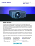
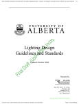
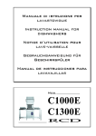
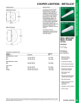
SERVIS BUILT-IN OVEN USER’S MANUAL Thank you for buying a Servis product. We hope you have pleasure using it and that it gives years and years ‘trouble-free’ service. This booklet has been prepared to help you get the most from your new product. Even if you are familiar with domestic appliances, please take a little time to read this booklet and familiarise yourself with your new appliance. Your safety is paramount; installation, maintenance and service must be carried-out by qualified, competent people. If you have any questions, please call the Service helpline on: 08444 15 55 24 or email us at: [email protected] The appliance was designed and made in accordance with the European standards EN 60 335-1 and EN 60 335-2-6 (electrical) plus relative amendments. The appliance conforms to the following EEC Directives: Low Voltage Equipment 73/23/EEC 93/68/EEC Electromagnetic Compatibility 89/336/EEC 92/31/EEC 93/68/EEC Oven Accessories 89/109WWC CONTENTS 1. Characteristics & Dimensions 2. Warnings 3. Installation and Use 4. Using Your Oven 5. Cleaning and Maintenance 6. Troubleshooting and Service PART 1: CHARACTERISTICS & DIMENSIONS LIST OF COMPONENTS : 1. Control Panel 2. Oven Door Handle 3. Oven Front Door 4. Child Lock (if fitted) 5. Tray 6. Oven Lower Element (behind the cover) 7. Oven Upper Element (behind the cover) 8. 9. 10. 11. 12. 13. Wire Rack Shelf Runners Oven Light Turbo Element (behind the cover) Turbo Fan (behind the cover) Air Outlet Holes PART 2: WARNINGS PLEASE READ THIS BOOKLET THOROUGHLY BEFORE INSTALLING AND SWITCHING ON THE APPLIANCE. THE MANUFACTURER ASSUMES NO RESPONSIBILITY FOR INCORRECT INSTALLATION AND USAGE. This appliance must be earthed. We strongly recommend that this appliance be installed by a N.I.C.I.E.C. registered engineer. • • • • • • • • • This appliance has been designed for home use and fitted within built-in furniture. The mains switch for the appliance must be accessible after installation After removing the packaging, please check if there is any damage to the appliance. If there is any damage, never attempt to use the appliance and immediately contact your Authorised Service Centre. As packaging materials (nylon, polyethylene bags, Styrofoam etc.) can be dangerous, especially for children, please ensure they are out of reach and disposed of in the most environmentally appropriate way. The appliance must be installed and commissioned by a suitably qualified or competent person, under the conditions provided by the manufacturer in this manual. The manufacturer cannot be held responsible for any damage that might occur due to faulty installation. Before connecting your appliance to the mains at home, please check the conformity of electricity supply, voltage, current and frequency and that it conforms to that specified on the information sticker attached to the appliance and/or packaging. Do not try and use your oven before it is fully installed. Be sure that all of its buttons are turned off when the appliance is not in use. Be sure that the feeder cable is not trapped during the installation of the appliance. The mains cable should never be replaced by the customer. In the event of any damage occurring to the mains cable for any reason, please contact your Authorised Service Centre. PART 2: WARNINGS (cont.) • • • • • • • • • Before replacing the oven light bulb, turn off the power to the appliance. Switch off the appliance before cleaning, maintenance work etc. Some parts of the appliance may keep their heat for a long time; please wait until the oven has cooled properly before carrying-out any maintenance, cleaning, replacing bulbs etc Do not keep flammable items/substances near the oven while it is in use. When operating other electrical devices near the oven, be careful not to let their cables come into contact with hot surfaces and parts. When the appliance is not in use, make sure that the buttons are in "0" (off) position. Your appliance needs sufficient air circulation whilst in use. Please read the part of this manual, where “installation procedures” are explained. This operating manual has been prepared jointly for multiple models. Some of the specifications explained in the manual may not be included in your appliance. Please look for explanations with the illustrations when reading the manual. Keep children away from the oven. SHOULD YOU REQUIRE ANY HELP OR ASSISTANCE WE RECOMMEND YOU CALL OUR AUTHORISED SERVICE CENTRE AND ONLY USE ORIGINAL SPARE PARTS. 4 PART 2: WARNINGS (cont.) • • • • • • • • • • • Please be aware of the following when using your appliance. That your appliance is properly earthed. Do not place the power cord of your appliance near any heated area. Pay special attention to the location of the hob. Should any damage occur to the power cord/lead, contact the Authorised Service Centre. For the models with timers, adjust the time prior to the first use or following a power failure. Heat and moisture will occur when your oven is in use. Make sure your kitchen is suitably ventilated. Before cooking for the first time, ensure that the oven is empty and its door closed. Heat the oven at the maximum temperature for 2 hours. This will allow the protective coating on the interior of the oven to be burnt off and for the associated smells to dissipate. Ensure adequate ventilation in the kitchen whilst ‘burning off’. Don’t be alarmed by the possibility of a little smoke being visible during this process. Do not touch interior parts when using the oven - it will be hot! After switching off, again remember not to touch it before it is completely cooled down. Do not put flammable and combustible materials into the oven. Do not place combustibles including any pressured container, paper, plastic and fabric near the hob surface. Be careful when using the oven; the oven outer surface can be hot. Keep children away. Do not let children climb on the door or sit on it. The times and numbers indicated on the printed material found with your oven are values obtained in a laboratory, according to relevant standards. These values may vary according to usage and the environment. Keep the appliance clean. Food deposits can be a fire risk. PART 3: INSTALLATION & USE The installation and maintenance listed in this part must only be carried out by qualified personnel. The manufacturer cannot be held responsible for any damage to persons or property resulting from an incorrect installation of this appliance. • • • Once the packing and wrapping has been removed from the outer surfaces and the various parts inside, check thoroughly that the appliance is in perfect condition. If you have any doubts do not install the appliance and call-in a qualified person. Some parts mounted on the appliance are protected by a plastic film. The protection must be removed before use. We recommend slitting the plastic along the edges with a sharp knife or pin. Do not move the oven by the handle. WARNINGS • The walls adjacent to and surrounding the appliances must be able to withstand an over temperature of 70 K. • The glue that joins the laminated plastic to the unit must be able to withstand a temperature of no less than 150°C, to avoid the plastic melting. • It is not recommended to fit an oven adjacent to a fridge or freezer. PART 3: INSTALLATION & USE (cont.) INSTALLING AND FIXING THE OVEN • The oven can be fitted into a tall cabinet or a base unit, making a cut-out as per the dimensions shown in the scheme below • You can use either cabinet 1 or cabinet 2 cut-out sizes. Take care with the details in the “circled areas” A and B below. • The oven must be supported by a base that will withstand its full weight. Screws re only used to locate the appliance inside its cabinet housing. Cabinet 2 Cabinet 1 A A DETAIL B DETAIL B Worktop Built-in hob Distance between worktop and Min.2.5cm control panel Control panel Built In oven Min. 5cm Distance between worktop and top panel of built in oven Insert the oven partly into the cabinet by pushing it forward into the space. Open the oven door and insert 4 screws into countersunk holes on the front-frame. Locate the spacers behind the flange of front frame and screw them till the surface of spacer touches the front frame. Whilst doing this, please take care that the chamfered edge of each spacer is faced to the rounded edge of the front frame. (see “C Detail” below. Push the product into the space and tighten the screws. Spacer Front frame C DETAIL C Mounting screw Wooden part PART 3: INSTALLATION & USE (cont.) ELECTRICAL CONNECTION The electrical connection must be carried out in accordance with the current standards and laws in force. Prior to connecting the oven check that: • the system and electrical sockets amperage is adequate for the appliance maximum power (see data label affixed on the back of the oven). • the socket or system has an effective earth connection in accordance with current standards and prescriptions of the law. All responsibility is disclaimed if this is not complied with. When connecting to the mains with a socket: • Fit a standardized plug, suitable for the load which is indicated on the rating plate, to the power cable. Connect the wires making sure they correspond as shown below, and remember that the earth wire must be longer than the phase wires: letter L (phase) = brown wire letter N (neutral) = blue wire symbol (earth) = green/yellow wire • The power cable must be laid so that no parts of it ever reach an over temperature of 75 K. • For connecting do not use, adapters or shunts as they could cause false contacts resulting in hazardous overheating. • The appliance must be placed in such way that the plug is accessible. 9 PART 3: INSTALLATION & USE (cont.) WIRING AND SAFETY OF THE BUILT-IN COMBINED OVEN : Wiring-in of the appliance must be performed by a qualified, competent person. The appliance is designed to connect to 220-240V and 380-415V 3N — electricity. If the mains electricity is different from the value given above, do not connect-up and seek advice from the Authorised Service Centre. Connection of the appliance must be made as per Figure 7 below. When connecting directly to the mains: • Install a multipolar switch that can withstand the appliance’s load, with a minimum opening between the contacts of 3 mm. Remember that the earth wire must not be cut out by the switch. • As an alternative, the electrical connection can also be protected with a high sensitivity RCD. • We strongly advise you to connect the green/yellow coloured earth wire to an effective earth system. 10 PART 4: USING YOUR OVEN Control Panel USING THE OVEN Oven Function Control Dial Select the oven function required (Figure 10) and then remember to set the thermostat (temperature required – Figure 11). Oven Thermostat (Temperature) Set the dial to the temperature you require. When the temperature inside the oven reaches the value set, the “thermostat light” will go out. During cooking, the thermostat light will continue to come back on and go out as the oven maintains the temperature set. 11 PART 4: USING YOUR OVEN (cont.) Table 1 12 PART 4: USING YOUR OVEN (cont.) Availability of the functions explained below vary according to model. Using the Functions of Your Oven De-Frost Function This function does not cook/ bake food; it only helps defrost it in a shorter time than if ‘left out’. Put the food to be defrosted on a wire rack and place on the third ‘runner’ from the bottom (Figure 12). To collect any melted ice, put an oven tray in the lowest position. Upper & Lower Heating Elements (Static Oven) In this type of cooking - ‘the traditional method’ - has heat emanating evenly from the lower and upper elements to cook food evenly. Remember to set the thermostat to the correct temperature. The cooking table provided is a guide. Preheating of the oven for about 10 minutes is recommended. This function is suggested for baking - cakes, pastry, baked pasta, lasagne, pizza. After you have finished cooking and turned the oven off the oven will take some time to cool down. Make sure no one touches the oven or parts of the oven until it has cooled down. Turbo Fan Function (Fan Cooking) The turbo fan function evenly disperses the heat around the oven. All foods on all shelf runner positions will be cooked evenly. Set the thermostat dial to the desired temperature. Turn the function dial to the Turbo function. We recommend pre-heating the oven for approx. 10 minutes. This function is suitable for cooking a number of dishes requiring the same temperature. 13 PART 4: USING YOUR OVEN (cont.) Fan with Upper & Lower Heating Elements (Fan Assisted) This is the position where the air coming from the lower and upper heating elements is circulated into the oven by the fan motor. Adjust the thermostat button to the required temperature. Turn the oven function dial so it will point to the symbol for this function. Adjust the oven timer (if required). Preheat the oven for about 10 minutes. Place the food in a suitable oven dish. This function ois recommended for cooking pastry. Suitable for cooking with one tray. After the cooking/baking, turn off the oven function dial and the temperature setting dial and cancel the timer program (if required). Remove the cooked/baked food; place it in a safe place and ensure the oven completely cools; opening the door speeds this process. Make sure no one touches the oven or parts of the oven until it has cooled down. Grill and Fan Grilling with Fan allows faster grilling, especially with larger surface areas of food and ‘skewered kebabs’. Place food on the grill pan/trivet and the pan on the highest shelf runner position. When grilling, the oven door must be closed and the oven temperature should be adjusted to 190°. Set the thermostat to the required temperature. After a preheating period of 5 minutes, place the food in the oven. After the cooking, turn off the oven function dial and the temperature setting dial. Remove the cooked/baked food; place it in a safe place and ensure the oven completely cools; opening the door speeds this process. Make sure no one touches the oven or parts of the oven until it has cooled down. 14 PART 4: USING YOUR OVEN (cont.) Turbo Fan & Lower Element Turbo Fan and the Lower Heating Element Function is ideal for cooking pizza. Whilst the turbo fan disperses heat evenly, the lower heating element ensures the pizza dough is baked properly. Turn the function dial to this symbol. After preheating for 10 minutes, place food in the oven. After the cooking, turn off the oven function control button and the thermostat button and cancel the timer program. Remove the cooked/baked food; place it in a safe place and ensure the oven completely cools; opening the door speeds this process. Make sure no one touches the oven or parts of the oven until it has cooled down. USING THE MECHANIC TIMER Please not that for normal use of the oven, the timer position should be set to ‘M’. When you bring the Timer button to the position indicating M as shown on the picture, the oven is in the ‘Manual’ position and can be used by setting the ‘Function’ with the ‘Temperature’. Please note that when the timer button is in the ‘0’ position the oven will not operate. Rotate the timer button clockwise to a certain time range between 0-100 minutes, as shown on the picture. The oven will stop when the set time is completed; the timer gives an audible warning once. 15 PART 4: USING YOUR OVEN (cont.) USING THE DIGITAL TIMER Setting the Clock The time should be set before using the oven. When the oven is connected to the power supply, the symbol (A) and the three "0"s on the screen will begin to flash. Whilst the screen is flashing the oven will not work, even if the control dials are set. Press the (+) and (-) keys simultaneously. The symbol will appear on the screen. Also, the dot in the middle of the screen will begin to flash. Using the (+) and (-) keys, adjust the time while this dot is flashing. After setting the time the dot stop flashing and be lit ‘permanently’. If the symbol (A) and the three « 0 »s on the screen flash, the oven cannot be operated using the control buttons. The symbol must be showing in order for the oven to work. Following any power failure, the clock will have to be re-set. Setting the Egg Timer/Minute Minder For egg timer/minute minder with audible alarm: Press the MODE key in the middle. The symbol will flash on the screen. Also, three “0”s will appear. Adjust the time period required by using (+) and ( -) keys while the symbol is flashing. Once set, the symbol stops flashing and stays lit. The alarm can be set to a time between the time range of 0.00 and 23.59 minutes. When the time is up, the timer gives an audible warning and the symbol begins to flash on the screen. Pressing any key will stop the audible warning and the symbol disappears. Oven Switch off after a Period of Cooking Time If you want to cook for a certain amount of time and for the oven to switch off at the end of it, set the required oven function and temperature. Place the food in the oven. Press the MODE button until you see “du r" on the screen. At the same time “A” will begin to flash. Using the (+) and (-) keys while the timer is in this position, set the hours and minutes duration required. Once set, wait a short time for the set clock time to re-appear and the “A” and to stop flashing and light continuously. The oven will also come-on and cooking start. 16 PART 4: USING YOUR OVEN (cont.) A cooking time between 0.00 and 10.00 hours may be set At the end of the set time, an audible alarm will be heard. Symbol “A” will begin to flash again and the oven will switch off. Set the control dials back to off/zero. Press any button on the timer to switch off the alarm. The oven will return to ‘maunal use’, the symbol will appear. Oven Switch Off at Set End Time If you want to cook until a certain end-time and for the oven to switch off at the end of it, set the required oven function and temperature. Place the food to be cooked into the oven. Press the MODE button until you see “En d" on the screen. At the same time “A” will begin to flash. Using the (+) and (-) keys while the timer is in this position, set the hours and minutes to the time you want to finish cooking. Once set, wait a short time for the set clock time to re-appear and the “A” and to stop flashing and light continuously. The oven will also come-on and cooking start. At the end of the set time, an audible alarm will be heard. Symbol “A” will begin to flash again and the oven will switch off. Set the control dials back to off/zero. Press any button on the timer to switch off the alarm. The oven will return to ‘manual use’, the symbol will appear. Setting the Start-time and End Time (Full Oven Programming) If you want to cook for a certain amount of time with a delayed start you need to set both the ‘End Time’ and the ‘Duration’ of cooking. Place the food to be cooked into the oven. Set the required oven function and temperature. Next: to set the duration of the cooking time follow the instructions in the section above called “Oven Switch off after a Period of Cooking Time”. Then follow the instructions in the section called “Oven Switch Off at Set End Time” setting the required end-time. The oven will also come-on at the required start time, determined by the duration and end times. At the end of the set ‘End’ time, an audible alarm will be heard. Symbol “A” will begin to flash again and the oven will switch off. Set the control dials back to off/zero. Press any button on the timer to switch off the alarm. The oven will return to ‘manual use’, the symbol will appear. 17 PART 4: USING YOUR OVEN (cont.) Oven Accessories Make sure you only use trays, casserole dishes, tins etc intended for use in an oven and always follow the manufacturers instructions fpr use. Be careful when positioning smaller containers on the wire shelves/racks. Always place a grill pan underneath any shelf where there is the possibility of spills or fat dripping off. Sometimes the grill pan can distort with the heat in the oven. It will return to its normal shape once cooled. Be careful when cooking with glass dishes or trays; avoid placing in cold liquids or cold environment immediately after using them in the oven. Ensure they cool off slowly, ideally placing them on a dry cloth. When using the grill we recommend you use the grill pan and ‘trivet’ supplied with this oven. Whenever possible avoid spills and drips on the oven cavity wall or floor. If you are using the grill pan to catch drips, it will be easier to clean afterwards if some water is added to the grill pan. When grilling use shelf position ‘4’ or ‘5’ (see below) and to prevent food sticking use a little oil on the grill before cooking. PART 5 : CLEANING AND MAINTENANCE CLEANING Before cleaning your oven, make sure it is switched off. Unplug the appliance. The oven should be cleaned after each use to remove cooking residuals like fats or sugar which, burnt afterwards, can encrust or form permanent stains and unpleasant smells. The oven should always be cleaned when it is still warm with soapy water, rinsed and dried properly on all surfaces. Never use abrasive powder cleaners or sponges. Also wash any accessory used. Do not leave ingredients like vinegar, coffee, milk, salty water, lemon juice or tomato sauce on enamelled surfaces for a long time. 18 PART 5 : CLEANING AND MAINTENANCE (cont.) Do not use acid-based detergents (check the information label on the product you are using). OVEN DOOR SEALS The condition of the oven seal is vital for the correct functioning and performance of the oven. We recommend you: clean it, avoiding abrasive tools or products. Check its condition occasionally. In case the seal has hardened or is damaged, contact your authorised service centre and avoid using the oven until it has been repaired. MAINTENANCE Prior to changing any parts it is absolutely essential to disconnect the appliance from the electricity mains. Maintenance must be carried out by a qualified, competent person. REPLACING ELECTRICAL COMPONENTS • To access the other electrical components the oven will have to be removed from the unit by unscrewing the mounting screws. • If the power cable needs changing always keep the earth wire longer than the phase wires and also follow all the instructions given in the “ELECTRICAL CONNECTION” section. CHANGING THE OVEN LAMP Attention: Before replacing the oven lamp, disconnect the appliance from the electricity supplies. If the oven lamp (C) has to be changed the new lamp must have the following rating: 15W - 230Vac - 50 Hz - E14 resistant to high temperatures (300°C). Turn glass protection cap (D) anti-clockwise and change the lamp (C). Put the cap back on taking care to insert the notches in the locking tangs and turn clockwise. C D A 19 B PART 6: TROUBLESHOOTING & TRANSPORTING In the unlikely event that you experience technical problems with your appliance please check the following before calling the Authorised Service Centre for technical assistance. PROBLEM SOLUTION The oven does not work •Check that the appliance has a mains supply. •Check that the knobs are set to the correct position. •If your oven has a manual timer check that it is in the MANUAL (M) position. •If you have an electronic programmer check that the symbol is visible. During cooking the thermostat pilot light is not on •The pilot light will cycle with the thermostat, this is normal. •Check that the knob is set to the correct position. The light inside the oven does not turn on •Check that the oven bulb is properly fitted. •If it has blown, replace it with a correctly rated bulb following the instructions given on Page 19 Transporting Your Oven If you have to transport your oven please protect it adequately paying particular attention to the glass and painted parts. Remember the inner glass door of the oven: this requires adequate protection when transporting the appliance; remove internal furniture and transport them separately. If you require assistance from your Authorised Service Centre Please call 08444 15 55 24 20 Servis Built In Unit 37 Suttons Business Park Reading Berkshire RG6 1HZ T: 0118 935 6100 F: 0118 966 1183 E: [email protected] W: servisbuiltin.co.uk 11.2007/R000 The symbol on the product or on its packaging indicates that this product may not be treated as household waste. Instead it shall be handed over to the applicable collection point for the recycling of electrical and electronic equipment. By ensuring this product is disposed of correctly, you will help prevent potential negative consequences for the environment and human health, which could otherwise be caused by inappropriate waste handling of this product. For more detailed information about recycling of this product, please contact your local city office, your household waste disposal service or the shop where you purchased the product. 52014148 144 10 253 207 203 201 242 205 202 18 38 32 2 10 4 19 252 253 251 7 12 125 112 126 114 31 144 252 30 29 CAVITY ASSEMBLY WITH CATALITIC PANEL AND WIRE SHELF (OPTIONAL) 16 32 111 4 200 110 144 253 61 10 266 144 19 253 13 12 68 10 61 266 19 61 61 253 252 253 252 144 144 266 252 CAVITY ASSEMBLY WITH CATALITIC PANEL AND WIRE SHELF (OPTIONAL) 266 252 CAVITY ASSEMBLY WITH CATALITIC PANEL AND WIRE SHELF (OPTIONAL) 4 140 19 4 20 21 9 117 116 115 143 TURNSPIT(OPTIONAL) RING HEATING ELEMENT(WITH FAN/WITHOUT (OPTIONAL) 15 17 112 TOP AND GRILL HEATING ELEMENT (OPTIONAL) TRAYS & GRID (OPTIONAL) 4 51 52 53 107 51 211 50 56 56 OVEN DOOR HANDLES (OPTIONAL) 4 51 54 53 4 52 OVEN DOOR ASSEMBLY (OUTER & INNER) 51 237 54 240 173 239 238 50 107 OVEN DOOR OUTER GLASS ASSEMBLY WITH INOX ADD-ON TYPES (OPTIONAL) 53 HANDLE ASSEMBLY GROUP (OPTIONAL) 51 55 241 50 241 51 220 4 220 261 261 THIRD INNER GLASS (OPTIONAL) OVEN DOOR TOP PANEL PARTS (OPTIONAL) 56 54 52 FLAT OVEN DOOR WITH FULL GLASS STRUCTURE (OPTIONAL) 70 197 79 152 81 70 197 79 81 152 82 82 77 197 79 197 152 152 76 75 74 73 77 80 78 76 80 72 METAL CONTROL PANEL ASSEMBLY 75 74 73 72 77 GLASS CONTROL PANEL ASSEMBLY (OPTIONAL) 124 89 113 113 113 137 ANALOG TIMER (OPTIONAL) DIGITAL TIMER (OPTIONAL) MECHANIC TIMER (OPTIONAL) GLASS CONTROL PANELS (OPTIONAL) 76 KNOBS (OPTIONAL) GLASS CONTROL PANELS WITH INOX ADD-ONS (OPTIONAL) KNOB ( SIGMA ) KNOB ( TETA ) HANDLE BODY (ELLIPSE ARC) HANDLE BODY (FLAT SLICE) HANDLE BODY (3D QUADRANGLE) KNOB ( ALFA ) KNOB ( GAMA ) KNOB ( ZETA ) KNOB ( DELTA RING ) HANDLE BODY (FLAT QUADRANGLE) HANDLE BODY (D PROFILE ARC) HANDLE BODY (METALUX) HANDLE WITHOUT FAN KNOB ( DELTA ) KNOB ( TRIO ) KNOB ( POP-IN ) HANDLE BODY (ARC TUBE) HANDLE BODY (ARC QUADRANGLE) HANDLE BODY (TRIO) Component 20612618 20612971 20612977 20613033 20613056 20613076 20615769 20616609 20617675 20628902 20645722 37002011 37004136 37004757 37007773 37008723 42019954 47000903 20642270 20642271 20642313 20645722 20656746 37002148 20659253 20659254 20628902 20645722 20659253 37002011 37002657 37004136 37004757 37007773 37008723 42019954 47000903 32001512 32001521 32001522 32001547 32001558 32001560 32001562 32002066 32002643 32003320 32003321 32005227 32001516 32005226 37001526 37001642 37001901 Description REAR PANEL (BUILT-IN,TERMINAL BOX) REAR INSULATION COVER (BUILT-IN) TRAY (60*60, DEEP, BLACK) BOTTOM HEATING ELEMENT HOLDER TOP INSULATION COVER (BUILT-IN) BOTTOM PANEL (BUILT-IN) CAVITY(BUILT-IN,GRILL,TURBO,LAMP,FAN) WRAPPING INSULATION (30X450X1750) FAN COVER (NO TURNSPIT,BLACK) FLAT PROFILE DOOR GROUP(BUILT-IN,66) DOUBLE GLAZED OVEN DOOR METAL TRIM(66,BI SCREW (M5*10, BLACK) OVEN DOOR HINGE (5,8-6,2 KG,GDA;14,5) SCREW (3.9*13, BLACK) SCREW (3.9*7.5, BLUNT TYPE, BLACK) SCREW (M5*10,BLACK) GRADUAL WASHER INNER GLASS ASSEMBLY(BUILT-IN,BLACK) SIDE PANEL (RIGHT, BUILT-IN) SIDE PANEL (LEFT, BUILT-IN) TOP PANEL (BUILT-IN,NEW) DOUBLE GLAZED OVEN DOOR METAL TRIM(66,BI GLASS FRONT PANEL GR (BLACK,I ADD-ON) SCREW (3.9*9.5, BLACK) OUTER GLASS ASSEMBLY(B-IN,I ADD-ON,BLACK FLAT PROF. COMPLETE DOOR(B-IN,I ADD-ON,B FLAT PROFILE DOOR GROUP(BUILT-IN,66) DOUBLE GLAZED OVEN DOOR METAL TRIM(66,BI OUTER GLASS ASSEMBLY(B-IN,I ADD-ON,BLACK SCREW (M5*10, BLACK) HANDLE BODY (D PROFILE ARC,INOX) OVEN DOOR HINGE (5,8-6,2 KG,GDA;14,5) SCREW (3.9*13, BLACK) SCREW (3.9*7.5, BLUNT TYPE, BLACK) SCREW (M5*10,BLACK) GRADUAL WASHER INNER GLASS ASSEMBLY(BUILT-IN,BLACK) SIGNAL LAMP LENS - RED 6mm OVEN LIGHT 230V FAN MOTOR 230V LIMIT THERMOSTAT NO 70ºC TOP AND GRILL HEATING ELEMENT(60*60,230V BOTTOM HEATING ELEMENT(60*60,230V 1100W) RING TUBULAR HEATING ELEMENT(230V,2000W) LIMIT THERMOSTAT NO 140ºC COOLING MOTOR 230V SILICONE CABLE(Ø0.85MM,SINGLE WIRE) SILICONE CABLE(Ø0.85MM,SINGLE WIRE) TERMINAL BOX WIRING HARNESS TERMINAL BOX -16A - 400V POWER CORD (UNPLUGGED,WHITE) SCREW (2.9*6.5 ) GRID (60*60,LOCKED) EXHAUST(BUILT-IN) Pos. Numbers 29 / 15 111 202 200 / 0 19 47 237 51 52 173 218 239 240 50 32 32 / / 72 4 54 46 47 237 54 51 56 52 173 218 239 240 50 77 2 9 / 112 110 20 205 201 0 / / 30 31 208 17 38 Codici AM 658000208 658000209 658000210 658000211 658000212 658000213 658000214 658000215 658000216 658000217 658000218 658000219 658000220 658000221 658000222 658000223 658000224 658000225 658000226 658000227 658000228 658000218 658000229 658000230 658000231 658000232 658000217 658000218 658000231 658000219 658000233 658000220 658000221 658000222 658000223 658000224 658000225 658000234 658000235 658000236 658000237 658000238 658000239 658000240 658000241 658000242 658000116 658000243 658000244 658000245 658000246 658000247 658000248 658000249 37001922 37001923 37001963 37002005 37002011 37002122 37002148 37002172 37002289 37002331 37002334 37002589 37002590 37002657 37002664 37002701 37002702 37002786 37002841 37002884 20625503 32001459 32001527 32001918 32002130 32002131 32002326 37002003 37003142 37004136 37004477 37004757 37006431 37007773 42006479 37007048 42006489 42008586 42009680 42009681 42009964 42015717 42024091 47000874 47000903 47002447 52003172 52003339 52003425 52003660 52005989 52006255 52014148 HINGE COUNTERPART (60*60,RIGHT) HINGE COUNTERPART (60*60,LEFT) COOLING FAN DUCT (BUILT-IN) SCREW (3.9*9.5) SCREW (M5*10, BLACK) SCREW (M5*18, BLACK) SCREW (3.9*9.5, BLACK) KNOB SPRING FAN ( 6 WINGS ) SCREW (3.9*6.5) THERMOSTAT BULB BRACKET SCREW (M4*8, BLACK) INSULATION WIRE (GALVANIZED STEEL) HANDLE BODY (D PROFILE ARC,INOX) SIDE PANEL BRACKET (BUILT-IN) HANDLE FIXING BUSH SCREW (4.2*9.5, BLUNT TYPE) TOP HEATING ELEMENT BULB BRACKET SCREW (3.5*25, BLACK) INNER PANEL GROUP INNER PANEL(B-IN,DIG.TMR,BLACK,GLASS PNL CAPILLARY THERMOSTAT 50-285°C DIGITAL TIMER FULL 230V T105 LED RED D FUNC.SELECT.SWITCH(MULTIFNC,HIGH END) SIGNAL LAMP BODY - 250V SIGNAL LAMP LENS - RED 9mm WIRING HARNESS SCREW (M4*6) SCREW (4*8) OVEN DOOR HINGE (5,8-6,2 KG,GDA;14,5) EXHAUST TOP PANEL (BUILT-IN) SCREW (3.9*13, BLACK) DEEP TRAY GRID 60*60 SCREW (3.9*7.5, BLUNT TYPE, BLACK) KNOB (DELTA RING, BUILT-IN TYPE, INOX) KNOB SEGMENT (WIRE) KNOB RING (DELTA, BLACK) SILICONE WASHER INNER PANEL RIGHT SIDE ADDITION INNER PANEL LEFT SIDE ADDITION OVEN DOOR GASKET (60*60) SPACER (BUILT-IN,BLACK) TIMER BUTTON (18.8MM,INOX) HORIZONTAL WOODEN SUPPORT (60*60) INNER GLASS ASSEMBLY(BUILT-IN,BLACK) ROCK WOOL (66,30,40KG/M3,REAR) SIDE STYROFOAM (BUILT-IN, 60*60) CORRUGATED LINER INNER GLASS STYROFOAM BUILT-IN HOB CARTON BOX CARTON BRACKET BUILT-IN HOB CARTON BOX USER MANUAL 12 12 203 4 / / 4 74 / 71 18 13 0 56 297 / 171 114 126 / 70 82 113 81 79 77 0 80 148 / 242 / 106 / 76 75 73 / 197 197 16 125 / 0 / 0 0 0 0 0 0 0 0 658000250 658000251 658000252 658000113 658000219 658000253 658000230 658000254 658000255 658000185 658000256 658000257 658000258 658000233 658000259 658000260 658000261 658000262 658000263 658000264 658000265 658000266 658000267 658000268 658000269 658000270 658000271 658000130 658000272 658000220 658000273 658000221 658000274 658000222 658000275 658000137 658000276 658000277 658000278 658000279 658000280 658000281 658000282 658000283 658000225 658000284 658000285 658000286 658000287 658000288 658000289 658000290 658000291