1
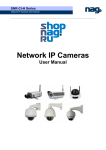
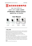
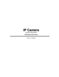
IP Camera Series
Model No.: GD2805
Thank you for using our IP Camera
Statement:
The actual product may differ from what is described in this
manual due to frequent update of our products and fast
development of technologies. If you meet any problems that
cannot be solved by reference to this manual, please contact our
Technical Support Department or our local dealers.
The content of this manual is subject to aperiodic update without
prior notice.
Note:
The IP Camera mentioned in this manual refers to web camera.
Click: Refers to clicking the left mouse button once.
Double click: Refers to quickly clicking the left mouse button twice.
Contents
1. Product
2. Structure
3. Installation
4. Specifications
5. Operations
Appendix I FAQS
Appendix II Network Ports Occupied by IP Camera
Appendix III Default Parameters
1. Product
1-1 Overview
IP Camera is an integrated IP camera solution. It adopts a single
high-integrality chip SOC Hi3510 (ARM+DSP) to implement
media processing with the integration of audio & video acquisition,
collection and network transmission in a card, which provides an
extremely high definition, high integrality and low cost solution
for LAN/WAN-based remote video monitoring device, that is, our
series IP camera products. Thus, users can quickly implement the
transition from analog monitoring camera products to digital
network camera products. This IP camera solution is applicable to
small & medium homes or business offices, as well as various
occasions needing the application of remote network video
transmission and monitoring. The product features easy
installation and simple operation.
1-2 Product Features
--Powerful high-performance programmable media processor
Hi3510, single chip SOC, embedded (ARM+DSP) and high-speed
video protocol processor;
--Supporting various high-sensitivity CCD or CMOS sensors
(SONY, SHARP, and so on), and supporting two types of video input
interfaces, that is, analog and digital video input interfaces;
--Adopting optimized H.264 video compression algorithm to easily
implement low-band width network transmission of highdefinition images;
--Supporting simultaneous browsing of a maximum of 10 users;
--Embedded Web Server to facilitate users to implement real-time
front-end monitoring and setting management by a standard IE;
--Supporting wireless network (WIFI/802.11b/g), mobile
networks (CDMA1X and GPRS), and monitoring by mobile phones;
--Providing an SD card slot to facilitate local image storage, 3 hours
recording video via 1G;
--Supporting remote system upgrade;
--Supporting dynamic domain name resolution, as well as LAN and
Internet (ADSL, Cable Modem);
--Supporting multiple network protocols: HTTP/TCP/IP/UDP/
STMP/DDNS/DNS/SNTP/DHCP/FTP;
--Supporting bi-directional call and voice broadcast;
--Network adaptation technology, supporting automatic video
frame rate adjustment according to the network bandwidth;
--Giving alarm in case of video loss or motion detection (settable
defense zone and sensitivity);
--Various embedded high-speed-dome and decoder protocol,
supporting transparent transmission protocols;
--Supporting image shielding/image snapshot;
--Automatic fault recovery, and automatic connection after
network interruption;
--Motion detection function, and may set detection time area.
1-3 Packing List
IP Camera
W--Fi Antenna for
IP Camera(Optional)
Network Cable
CD-ROM
AUDIO I/O Cable
9V/1A Adapter
User Manual
2. Structure
2-1 Front Panel
Rotate Axis
Lens
IR LEDs
Built-in
Microphone
Base
2-2 Rear Panel
Wi-Fi Antenna
(Optional)
Power On/Off
Network Cable
Port
Audio I/O
Reset Button
9V/1A
Power Socket
SD Card Slot
2-3 Rear Panel Connection Diagram
Interface description:
: Ethernet interface;
:SD memory card slot;
OFF/ON: Power switch (ON: turns on; OFF: turns off);
DC9V: Power input, DC 9V/1A;
A/V OUT: Audio output. Audio IN is white, Audio Out is red;
: Parameter reset button, Reset to default.
3. Inatallation
If you choose Wi-Fi Module, Connect the antenna to IP Camera.
Access the IP Camera to your network or connect it to your PC via a
network cable. Connect the adapter to IP camera. In normal network
conditions, the network connection LED indicator (orange) will light up
in five seconds, indicating the completion of the physical connection of
the IP Camera.
Network Cable
4. Specifications
Item
Video input
Video compression
Video resolution
Video parameter
adjustment
CMOS
parameter
adjustment
Stream format
Video frame rate
Video compression
code rate
Recording Video
Audio input
Audio compression
Audio output
Call input
Communication
interface
Input power
Maximum power
Operating temperature
Operating humidity
Storage temperature
System requirement
Wi-Fi Modele
Value
PAL and NTSC
H.264 baseline profile@Level 2.2
PAL: 320*240(QVGA), 640*480(VGA)
NTSC: 320*240(QVGA), 640*480(VGA)
Brightness, chrominance, contrast,
saturation, and image quality
Automatic white balance (AWB), automatic
gain control (AGC), backlight
compensation (BLC), automatic light
control /electronic light control (ALC/ELC)
Pure video stream or composite video & audio
stream
PAL: 1-25 frame/second;
NTSC: 1 - 30frame/second;
16Kbit/S~8Mbit/S
3 hours video/1G
One linear input, impedance: 2.2K ohm
G.726
One linear output
One microphone input.Built-in optional.White
for microphone outside and red for built-in.
One 10M/100Madaptive Ethernet interface
DC 9V /1A
Less than 6W
-10 ~ +55
10 ~ 85%
-20 ~+70
Operating system: Microsoft Windows 2000/
XP/2003
Brower: Microsoft Internet Explorer 5.0
or above
Supporting IEEE802.11b/g wireless network;
5. Operation
5-1 Connection Check
1.The default IP address of each IP Camera is 192.168.1.1, and the
default subnet mask is 255.255.255.0. Change the IP address of
your computer to be in the same network section as the IP Camera,
for example: 192.168.1.69, and the subnet mask shall also be the
same.
2. Test whether the IP Camera starts normally and is connected
normally: In the WINDOWS operating system, select Start run
command, open the command line window, and enter the
following in the command line window: ping 192.168.1.1
Check whether the IP Camera can be pinged through. If it can be
pinged through, it indicates that the IP Camera is normal and the
network connection is correct. Then, run the Search NVS software
to modify the network parameters of the device. (For example:
modifying such parameters as IP address, subnet mask and
gateway, to facilitate the device to operate over the local network. )
The use of the software will be detailed in the following. If it cannot
be pinged through, please check the settings of the IP address and
gateway of the PC are correct and whether the network cable is
connected correctly.
5-2 Retrieving Device and Network
Parameter Modifications
[Description]: Use the Search NVS software to retrieve the
device and modified network parameters over a different network.
The running path of the Search NVS is as follows:
1.In the delivery-attached product CD, find the Search NVS in the
tool software directory and copy it to the PC.
2.After installing the center management software, find the Search
NVS software by selecting Start All Programs NVS Center500.
Note: When running the Search NVS software to search and
change its network parameters, since the Search NVS software uses
multicast protocol to search network information of the device over
different network sections, the firewall does not allow passing of
multiple packets. Therefore, disable the firewall first to obtain the
network information of the device.
1 Run the Search NVS, and click <Search>, as shown in the
following figure:
[Connect NVS Local IP] shows the local IP address of the
currently connected device. If the current PC has multiple network
interface cards or multiple local IP addresses, please select an IP
address for connection with the NVS.
In [Display Device Information Area], you can view device
name, model, number of channels, IP, subnet mask, gateway,
communication port, Web port, multicast address, multicast port,
DNS, and physical address.
2 Select IP Camera, click <Set Parameters>, and the
following interface appears:
Change network parameters, click <OK>, and the IP Camera
automatically restarts.
5-3 Accessing IP Camera via IE Explorer
When it is the first time to access the IP Camera via the IE (Internet
Explorer), plug-ins shall be installed.
Two methods are available for plug-in installation:
1. Automatic installation
You must reduce the IE security setting level temporarily so that
the ActiveX components can be installed in your PC as follows:
Select Internet Options from the Tools bar;
Click the Security tab and pay attention to your current
security settings;
Set the Security Level to Low, and click <Apply>;
Enter the IP Camera address in the address bar of the IE (such as:
hhdemo1.vicp.net) or click the demonstration link to open the
IE window. If an alert box appears to ask you whether you want
to install ActiveX, click <Yes > to start installation.
Once the installation of the ActiveX is completed, recover the
security settings to the default value.
2. Download and installation
Access the IP Camera address. First download the control
compression package from the IP Camera, extract it to a temporary
directory, close all IE pages, and finally double click to extract the
install.bat file under the directory and start installation, as shown
in the following figure:
After the completion of the installation, the system will prompt the
successful installation, as shown in the following figure:
After the control file is downloaded, extract and run the Install.bat
file, and the system will automatically
install the control. After successful
installation, the following
interface appears
3. Open the IE (Internet Explorer), enter the IP address 192.168.1.1
of the IP Camera, and the login box appears, as follows:
Enter the user name (default user name: admin) and password
(default password: admin), and click <O K> to enter the main
interface, as follows:
Brightness
Contrast
Chrominance
Saturation
Rotator
Control
Image display area
Speaker: listening button, press this button to enable the listening
function; if this button pops up, the listening function is disabled;
if a different channel is selected, the listening channel also changes.
Record: First select a channel to be recorded, and then click
<Record> to start or stop recording.
Snap: Select a channel to be recorded, click <Snap>, and the
current image will be saved as a file;
Replay: Click <Replay>, and the player appears. Select a
recorded file to play back;
Call: Press this button to enable the call function. When the button
pops up, the call function is disabled;
Alarm: Call <Alarm> to clear all IP camera alarms temporarily;
Rotator Control: Select a channel, and then conduct up/down/
left/right rotator operations (each channel shall first be configured
with a decoder protocol, and make sure the decoder is connected
correctly).
5-4 Settings of IP Camera Parameters
5-4-1 System Setting of IP Camera
Only the system administrator can log in to enter the parameter
setting interface of the IP Camera.
Click <System>, the IP Camera parameter setting interface
appears, as shown in the following figure:
The interface for setting System parameters of the IP Camera is as
shown in the above figure. You may set the time, name and ID of the
IP Camera.
[Upgrade]: Click <Browse>, select a correct upgrade file
(both the path and type shall be correct), and click <Upgrade>
to start upgrade. After the completion of upgrade, the system will
prompt the successful upgrade, and the IP Camera will
automatically reboot.
For example: The currently operated device is an IP Camera, with
the version as shown in the above figure (5.0.0.6). Get the latest
version of the IP Camera from the manufacturer (file name: auto1
D1_V5007; version: 5.0.0.7), and then click <Browse>. Select
the file auto1D1_V5007, click <Upgrade>, and it starts to
download the file to the IP Camera. After the completion of the
download, the IP Camera will write the file into its FLASH chip.
During this process, it will show the upgraded percentage. After the
completion of upgrade, the system will prompt the successful
upgrade, and the IP Camera will automatically reboot. Log on again
to enter the setting interface and check whether the version number
matches the upgraded one.
Note: During the upgrade, make sure that the power and
network of the IP Camera are not disconnected.
[Storage parameter]: Used to set the harddisk position for
storing recorded files and snapshots.
Set the file packing time. The storage path is: Disk letter:\XDNVS.
Directory for storing snapshots: C:\XDNSV by default.
[Restore Default]: Used to restore all parameters of the IP
Camera (including network parameters, excluding physical
address) to their default settings.
Please use this function prudently!
[Reboot]: Used to reboot the IP Camera. The IP Camera will
reboot in about five seconds.
5-4-2 Setting Network Parameters of IP Camera
The interface for setting the Network parameters of the IP Camera
is as follows:
You may set the IP address, subnet mask, gateway, physical address,
communication UDP port, and TCP data transmission port. For a
pplication in a LAN, please pay attention to avoid the conflict
between the IP address with the internal computer IP address in
the LAN.
[HTTP port No.]: Changing the Web port can change the IE
access port provided by the Web Server inside the IP Camera.
[MAC]: MAC address refers to the physical address of the network
interface card in the device. Do not change this setting at will
unless it is necessary.
[DDNS Parameters]: After the DDNS function is enabled, the IP
Camera will automatically report its own IP address (LAN) and the
dynamical IP addresses of such dial-up devices as router to the
DDNS Server periodically. In addition, you need to set DDNS server
URL or DDNS regName, DDNS server Port (3000 by default), HTTP
port map No. and Data port map No. of the IP Camera. If the address
of the DDNS Server is the domain name, fill in the DNS address
correctly.
[DNS address]: If the address of the DDNS Server or the center
address is the domain name, fill in the DNS address correctly.
Note: After the network parameters of the IP Camera are modified,
the device will automatically reboot.
By default, the IP Camera occupies the following network ports:
TCP
UDP
80 (Web port)
5000 (communication port, audio & video
data transmission port, call data transmission port)
5000 (audio & video data transmission port)
Default network parameters:
IP address: 192.168.1.1
Subnet mask: 255.255.255.0
COM port: 5000
Web port: 80
Gateway: 192.168.1.254
DHCP: Disabled
5-4-3 Setting Advanced Parameters of IP Camera
The interface for setting the Advanced parameters of the IP
Camera is as follows:
[Alarm send mail]: If an alarm is generated, an E-mail or
snapshots of the front end can be sent to the set MAIL box.
[UPNP parameters]: If the UPNP is enabled, the DVS can
.
automatically map the data port and WEB port to the router
according to the settings. An extranet can access the Intranet via
the mapped ports
5-4-4 Setting User Manage Parameters of IP Camera
The interface for setting the User Manage parameters of the IP
Camera is as follows:
Each IP Camera can be configured with two users: one is an
administrator, and the other is a common user. The administrator
can set the parameters of the IP Camera, while the common user
does not have the right to make such settings.
Default username of administrator:
adminPassword: admin
Default username of common user 1: user1 Password: 1
Note: Both username and password are case-sensitive.
5-4-5 Setting Video Parameters of IP Camera
The interface for setting the Video parameters of the IP Camera is
as follows:
[Audio]: Used to set whether to enable the audio function of the
IP Camera. In some occasions, it is not necessary to provide the
audio function, please disable the audio input to save DSP
resources and network resources. (Note: the audio switch is not
enabled by default. )
[Image size]: Used to set the resolution of images. You may
select a resolution of coding formats VGA and QVGA.
[Quality]: Used to select image quality. Fine is selected by
default. It is selected according to network status, such as below:
BandWidth
Resolutions
Image Quality
[Environment Power Frequency]: Used to select the power
frequency of the operating environment. Incorrect selection may
cause image blinking.
We suggest normally that you use OUT DOOR model which image
quality is best. OUT DOOR model is suitable to be used indoor.
Please set according to frequency of lamp power if you find lamp
flashing make image flash.
[Mirror]: Image mirror switch;
[Flip]: Image flip switch.
Set the image mask area (the image is divided into 22 * 18 blocks.
Double click a block to be masked, and set or cancel the mask
setting of the block. The image mask area only supports the
masking of one area; otherwise, the diagonals of two areas to
form a geometric figure to represent the image mask area).
[Area set]: Click and drag the mouse to delimit the detection area.
[Clr]: Used to clear set motion detection area.
[All]: Indicates the entire video area is the motion detection area.
After the parameters are set, click <Save>, and the settings take
effect.
5-4-6 Setting Motion Parameters of IP Camera
The interface for setting the Motion parameters of the IP Camera
is as follows:
In this interface, you may set the video motion alarm parameters of
each channel: Motion detection area (the image is divided into
22 * 18 blocks. Double click a block to be set, and set or cancel the
motion detection settings), alarm detection time (arming time),
alarm detection switch, and motion alarm detection sensitivity.
[Area set]: Click and drag the mouse to delimit the detection area.
[Clr]: Used to clear set motion detection area.
[All]: Indicates the entire video area is the motion detection area.
[Schedule]: Used to set different time segments for motion
detection. For example, starting with 00: 00, and ending at 23: 59
every day.
[Everyday]: Turns on the motion detection switch to enter the
arming status.
After the parameters are set, click <Save>, and the settings take
effect.
Appendix I FAQS
Default Parameters
IP address: 192.168.1.
default administrator and username:Admin password: Admin
Subnet mask: 255.255.255. 0
Default username of common user 1: user1 password: 1
Gateway:
192.168.1.254
COM port: 5000
Web port:
80
DHCP:
Disabled
The IP Camera occupies the following network ports:
TCP
80 (Web port)
May be modified
by the user
UDP
5000 (audio & video
data transmission port)
5000 (communication port,
audio & video data transmission
port, call data transmission port)
May be modified by the user
Forgetting password
Solution: Press <RESET> in the rear panel of the IP Camera to
restore all parameters to their default values.
Note: Those who are not service-trained professionals shall not
press the <RESET> key. After resetting, all parameters will be
recovered to their default values (excluding the physical address of
the network).
No plug-in display in IE
Possible cause: No plug-in is installed?
Solution: If it is the first time to use the IE (Internet Explorer) to
access the IP Camera, plug-ins shall be installed:
Two installation methods are available:
(1) Automatic installation
You must reduce the IE security setting level temporarily so that
the ActiveX components can be installed in your PC as follows:
Select Internet Options from the Tools bar;
Click the Security tab and pay attention to your current security
settings;
Set the Security Level to Low, and click <Apply>;
Enter the IP Camera address in the address bar of the IE (such as:
hhdemo1.vicp.net) or click the demonstration link to open the IE
window. If an alert box appears to ask you whether you want to
install ActiveX, click <Yes > to start installation;
Once the installation of the ActiveX is completed, recover the
security settings to the default value.
(2) Download and installation
First download the control compression package from the IP
Camera, extract it to a temporary directory, close all IE pages,
and finally double click to extract the install.bat file under the
directory and start installation. After completion of the
installation, the system will prompt you that it is installed
successfully.
Why an error occurs when accessing the IP Camera via
the IE after upgrade?
Solution: Delete the cache of the IE as follows: Select the Tools
menu of the IE, and select Internet Options. Click
<Delete Files> in the second entry (Internet Temporary
Files), select Delete All Offline Content check box and then
click <OK>. Log in to the IP Camera again.
Video failure after program upgrade
Solution: Close all browse pages, find files HHNetClient.dll and
XDView.ocx under the system directory C:\, and delete them.
Then, use the IE to reconnect the IP Camera, and the IP Camera
will automatically update play plug-ins.
Failure in accessing IP Camera via IE
Possible cause 1: Network interruption?
Solution: Use a PC to access the network to test whether the
network access is normal. First remove cable fault, network fault
caused by viruses until mutual successful pinging between the IP
Camera and PC.
Possible cause 2: IP address occupied by other device?
Solution: Disconnect the connection between the IP Camera and
the network, independently connect the IP Camera to the PC,
and reset the IP address according to proper recommendations.
Possible cause 3: IP address in a different subnet?
Solution: Check the settings of IP address and subnet mask
address of the Server, as well as the gateway settings.
Possible cause 4: Any conflict between the physical address over
the network and the IP Camera?
Solution: Change the physical address of the IP Camera.
Possible cause 5: Web port changed?
Solution: Contact the administrator to obtain related port
information.
Possible cause 6: Unknown?
Solution: Press the <RESET> key in the rear panel of the Server
to restore the default settings, and then make reconnection. By
default, the IP address is 192.168.55.160, and the subnet mask is
255.255.255.0.
Abnormal image display color (green or other colors)
Solution: Due to the difference of graphic card, sometimes, the
images of the IP Camera cannot be displayed normally, and are
displayed in green or other colors. In this case, run the extracted
Config.exe file (or run C:\Winnt\system32\Config.exe) to set
the display buffer area: automatic detection, use graphic
memory or memory in a fixed manner, and open the IE again to
connect the IP Camera.
No sound upon listening
Possible cause 1: No audio input?
Solution: Check the audio connection of the main unit
Possible cause 2: Has not audio option of the related channel of
the IP Camera been enabled?
Solution: Check the audio parameter settings of the IP Camera,
and check whether the audio function is enabled.
Bad audio effect
Possible cause: If serious noise and distortion phenomenon
appears, check whether the input signal level is the line input.
In most such cases. when the input signal is not the line input
(such as an active microphone with amplifier), it does not match
the input level of the IP Camera, causing saturation distortion.
Solution: Use appropriate line input according the acceptable
range of the IP Camera.
Why normal data cannot pass a switch
1. For an L2 switch, possibly a wrong address is written.
2. For an L3 switch, check whether the port is bound with the
physical address.
3. Is the Server considered when the firewall rules are
configured?
Before locating the network fault, please use the Ping command
to connect the peer address in the command line mode. Checking
the returned information after the pinging process is an
important step. If the ping fails, it indicates that a fault occurs to
the network. If the IP and MAC addresses are bound, it is
necessary to make such settings inside the switch. Add a new
binding, that is, the binding of the IP address of the IP Camera
with the MAC address. If the Server is not considered when
configuring the firewall rules for the switch, please refer to the
port number used by the IP Camera, and reconfigure the switch.
How to use the IP Camera to transmit audio & video
data over the Internet?
For the IP Camera to transmit audio & video data over the
Internet, first know you own network access mode: For static IP
address of the Internet, directly set the IP address, subnet mask
and gateway of the Server to the static address provided by the
ISP, and you will be able to browse normally. In addition, the
currently two widest applied access modes, ADSL and community
broadband network need the authentication process. The
authentication can be completed by some intelligent devices such
as PCs or small routers. Inside the LAN, there is no IP address of
the Internet, so an Extranet cannot access the LAN. In this case,
some settings shall be made in the access server.
Solution:
1. In applications in a LAN in offices or buildings, if you want to
access the IP Camera from other cities, you may use the IP Camera
accessing to the Internet to make forwarding. Use port mapping to
forward information packets. Use some current popular port
mapping software to make simple settings, for example, Portmap
and portunnel. Select all IP addresses among the access IP
addresses, and then fill in the address of the IP Camera inside the
LAN.
2. It is also a good solution to select a router as the forwarding
device if no PC is available. Presently most routers provide port
mapping function (DMZ). Directly designate the DMZ address as
the address of the IP Camera.
Appendix II Network Ports Occupied
by IP Camera
By default, the IP Camera occupies the following network ports:
TCP
UDP
80 (Web port)
5000 (communication port,
audio & video data
transmission port, call data
transmission port)
5000 (audio & video
data transmission port)
Multicast port
Multicast start port + channel Number
Please pay attention to the port No. occupied by the IP Camera
upon port mapping configuration.
Appendix III Default Parameters
Default network parameters:
P address:192.168.1.1
Gateway:192.168.1.254
Web port: 80
DDNS:Disabled
Subnet mask:255.255.255. 0
COM port:5000
DHCP:Disabled
Username and password:
Default administrator username:admin Password: admin
Default username for common user 1:user1Password: 1
FCC information
This device complies with part15 of the FCC Rules. Operation is subject
to the following two conditions:
(1) this device may not cause harmful interference,
(2) this device must accept any interference received, including
interference that may cause undesired operation.
Changes or modifications not expressly approved by the party responsible
for compliance could void the user s authority to operate the
equipment.