1
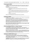
Hardware Installation Guide
A GUIDE FOR THE PHYSICAL INSTALLATION OF THE DATASTORM MOUNT
MotoSAT Corporation
Updated July 25, 2003
This guide is provided as a help and not a total solution for every installation.
Common sense and concern for customers equipment will make for a good installation.
IMPORTANT INFORMATION
PLEASE READ
2
This guide is provided as a help and not a total solution for every installation.
Common sense and concern for customers equipment will make for a good installation.
MotoSAT DataStorm Mobile Two-Way Internet
User’s Manual Addendum
Regulatory Information
This device complies with Part 15 of the FCC Rules. Operation is
subject to the following two conditions: (1) this device may not cause
harmful interference, and (2) this device must accept any interference
received, including interference that may cause undesired operation.
The Lower Control Unit (LCU-1) and Upper Control Unit (UCU-1)
components of the DataStorm (together “the equipment”), and the
associated connections, have been tested and found to comply with the
limits for a Class B digital device, pursuant to Part 15 of the FCC Rules.
These limits are designed to provide reasonable protection against harmful
interference in a residential installation. This equipment generates uses
and can radiate radio frequency energy and, if not installed and used in
accordance with the instructions, may cause harmful interference to radio
communications. However, there is no guarantee that interference will not
occur in a particular installation. If this equipment does cause harmful
interference to radio or television reception, which can be determined by
turning the equipment off and on, the user is encouraged to try to correct
the interference by one or more of the following measures:
• Reorient or relocate the receiving antenna.
• Increase the separation between the equipment and receiver.
• Connect the equipment into an outlet on a circuit different from
that to which the receiver is connected.
• Consult the dealer or an experienced radio/TV technician for
help.
Changes or modifications not approved by MotoSAT [Mobile
Technology, Inc.] for compliance could void the user’s authority to
operate the equipment.
3
This guide is provided as a help and not a total solution for every installation.
Common sense and concern for customers equipment will make for a good installation.
INSTALLATION GUIDE
FOR PHYSICAL INSTALLATION OF
THE DATASTORM MOUNT
FIRST STEP……………………………………………………… 4
MINIMUM REQUIREMENTS ……………………………………………………………
4
RECOMMENDED TOOLS……………………………………………………………………… 5
RECOMMENDED HARDWARE……………………………………………………………… 6
INSTALLATION PROCEDURES:
STEP 1.
UNPACKING THE DISH FROM THE SHIPPING CRATE ………………
8
STEP 2.
REMOVING MOUNTING PLATE FROM THE DISH ……………………………
8
STEP 3.
FINDING A GOOD MOUNTING LOCATION ………………………………………… 9
STEP 4.
MARKING THE POSITION OF THE MOUNTING PLATE…………………
11
STEP 5.
PRE-SEALING THE ROOF……………………………………………………………………………
STEP 6.
PLACE THE MOUNTING PLATE AND SCREW INTO PLACE…………
12
STEP 7.
DISH TO MOUNTING PLATE ………………………………………………………………… 13
STEP 8.
RUNNING WIRES …………………………………………………………………………………………
STEP 9.
CONNECTING MAIN CONTROLLER AND MODEMS ……………………
20
STEP 10.
CONNECTING THE COMPUTER…………………………………………………………………
23
SPECIFICATIONS…………………………………………………………………………………………………………
25
SATELLITE TV ADAPTORS (BOW)………………………………………………………………………
27
4
11
13
This guide is provided as a help and not a total solution for every installation.
Common sense and concern for customers equipment will make for a good installation.
FIRST STEP
The first step of installation is to get a special Billing ID. The Billing ID is used when you load the DIRECWAY software to the
computer for the first time. These billing ID’s are unique for the TFES (Transportable Fixed Earth Station) DataStorm
system. Billing ID’s are provided by Hughes to bandwidth resellers.
Please contact your Bandwidth Provider for your billing ID. If you do not know who your bandwidth provider is, please
contact your dealer.
OBTAINING A BILLING ID
Make sure the customer knows which Internet Package they would like, and whether or not they desire to have the Satellite
TV option. Questions like “Do they require a Static IP address?”… Or “Do they plan to have more than one computer using
the Internet Connection?” …need to be known prior to getting the Billing ID.
Please get a Billing ID as soon as possible… Prior to Installation. Doing this could shorten the Installation
time by hours. (Not Joking)
MINIMUM REQUIREMENTS
ROOF SPACE MINIMUM REQUIREMENTS
The DataStorm requires a 56” x 40” area in the center top of the vehicle to mount. Visually check to make certain that the
dish arm does not hit any other mounted antenna or other device such as an Air Conditioner as it rotates on its axis.
COMPUTER MINIMUM REQUIREMENTS
•
•
•
•
•
Pentium III 500 MHz or Celeron at 800 MHz.
128 Megs RAM.
120 Megs hard drive space.
CD-ROM Drive.
Windows 2000 Professional, XP Home or Professional
5
This guide is provided as a help and not a total solution for every installation.
Common sense and concern for customers equipment will make for a good installation.
•
•
•
•
•
Available USB Port.
Available Serial Port.
A working Dial-up Modem (for one time connection to activate dish)
System Disk for Windows (if some required programs were not installed originally on your windows system).
800 x 600 monitor display
RECOMMENDED TOOLS
Power Screwdriver - A Short head driver is good for tight situations.
Stud Finder Tape Measure Volt Meter
Fish Tape
Hole Drill Wire Strippers TC-360 DLS Electronics
(Different sizes)
Coax Cable Crimping tool
Coax Cable Stripper Long Drill Bit for
Pilot Holes
6
This guide is provided as a help and not a total solution for every installation.
Common sense and concern for customers equipment will make for a good installation.
7/16
Screw Driver Mini Screwdriver
Open Ended Wrench Philips #2
Flat Blade
RECOMMENDED HARDWARE
USE THE PROPER SCREWS FOR THE TYPE OF ROOF YOU HAVE.
Stainless Steel Hardware is ALWAYS recommended.
Fiberglass
Roof
Metal
Roof Only
Wood or Composite
Roof
Screw size recommended (depending on roof structure) #14X1”
FIBERGLASS ROOFS – Must pre-drill. Self-tapping screws will chew up and damage the roof. Use non-self tapping screws.
METAL ROOF
- Metal roofs may use self-tapping screws.
WOOD OR COMPOSITE – Sheet Metal Type, non-self tapping screws.
OTHER RECOMMENDED HARDWARE
Cable Clamps
Zip Tie Straps
Dicor Sealant
7
This guide is provided as a help and not a total solution for every installation.
Common sense and concern for customers equipment will make for a good installation.
COMMON SENSE
Dielectric Grease
We strongly recommend that DICOR roof sealant be used with any job where holes need to be sealed on a vehicle. Dicor
has proven to be superior to other silicon sealants.
Dielectric Grease is needed to create a water tight barrier for electronic connections. Please make sure that the grease
you are using is dielectric, which means it does not conduct electricity.
COAX CABLE (also know as RG6)
The DataStorm is shipped with 30’ of coax cable to wire your system. If you choose to purchase additional coax cable, it
MUST be of a high quality and swept-tested.
COAX CABLE CONNECTORS
MotoSAT insists that you use coax connectors that do not have a rubber washer for weatherproofing. We recommend
using very high-grade connectors and sealing them with Dielectric grease upon installation. These connectors are exposed
to severe weather and should be treated as vital connections.
STEP 1. UNPACKING THE DISH FROM THE SHIPPING CRATE
Remove the screws that hold the DataStorm to the shipping crate and remove the DataStorm Dish.
RAISING THE DISH MANUALLY - To raise the dish after unpacking it from the shipping crate, find the Control Cable that is
connected to the mount. You’ll notice two wire leads (Red & Orange) sticking out from the Control Cable. To raise the dish,
connect the Red lead to a positive 12-volt or 9 volt lead, and the Orange lead to negative. (Use of a Power Screwdriver
battery is also recommended). Reverse the leads to lower the dish.
8
This guide is provided as a help and not a total solution for every installation.
Common sense and concern for customers equipment will make for a good installation.
WARNING – WHEN RAISING THE DISH MANUALLY, THE CONTROL CABLE MUST NOT BE CONNECTED TO THE MAIN
CONTROLLER! If the control cable is connected to the Main Controller when you manually move the dish, you will damage
the internal circuitry. If the Control Cable is already connected to the Main Controller and you want to raise or lower the
dish manually, DISCONNECT the Control Cable from the Main Controller FIRST.
STEP 2. REMOVING MOUNTING PLATE FROM THE DISH (OPTIONAL, you do not have to remove the
mount from the mounting plate for installation. It may be helpful in some situations.)
Four screws attach the Dish Mount to the Dish Mounting Plate. Locate and remove the four screws and lift the Mount off the
mounting plate.
STEP 3. FINDING A GOOD MOUNTING LOCATION
9
This guide is provided as a help and not a total solution for every installation.
Common sense and concern for customers equipment will make for a good installation.
REAR
WARNING - Make sure the roller side of mount faces the REAR of the vehicle.
Place the Mounting plate in the center of the Roof. Use a Stud Finder to help you find cross beams that line up with some of
the holes. Screwing into cross beams help secure the DataStorm to the roof and provide good stability.
Make certain that you have at least 7 inches between the roller bar and any item behind the bar.
10
This guide is provided as a help and not a total solution for every installation.
Common sense and concern for customers equipment will make for a good installation.
STEP 4. MARKING THE POSITION OF THE MOUNTING PLATE
You will need to mark the corners of the mounting plate as well as the holes you intend to drill through for later
realignment. Notches are located in each end of the mounting plate to be used for relocating of the mounting plate after
pre drilling the mounting holes. Mark and use for realignment.
STEP 5. PRE-SEALING THE ROOF
11
This guide is provided as a help and not a total solution for every installation.
Common sense and concern for customers equipment will make for a good installation.
Lift the Mounting Plate, and Pre-Fill all holes to be used.
Note: When pre drilling, drill and then fill the hole, when using self-tapping screws, use the technique shown above.
STEP 6. PLACE THE MOUNTING PLATE AND SCREW INTO PLACE
Note:
The Mounting Plate comes
with predrilled holes. When securing
the mount to the roof, use as many of
the holes as required for the job.
Know your roof structure and
capabilities.
CAREFULLY move the mounting plate over holes and slowly drop it into place. Center the holes over each marking and
press down slightly on plate. Once centered, attach the plate to the roof with short screws.
NOTE - In the illustrated installation, the roof is rubber on top of a wood foundation.
12
This guide is provided as a help and not a total solution for every installation.
Common sense and concern for customers equipment will make for a good installation.
NO!
YES!
Cover up each screw with Dicor to prevent moisture penetration.
STEP 7. ATTACHING DISH TO MOUNTING PLATE
13
This guide is provided as a help and not a total solution for every installation.
Common sense and concern for customers equipment will make for a good installation.
IMPORTANT
ALWAYS
1.
Loosen the 4 bolts that attach the
mount to the Stabilizing Rails and
then loosen the nuts on each of the
Stabilizing Rails.
2.
Then, retighten the 4 bolts that
attach the mount to the Stabilizing
followed by retightening the nuts
on the Stabilizing Rails (in that
order).
FAILURE TO FOLLOW THIS
PROCEEDURE CAN RESULT IN BINDING
OF THE AZIMUTH ROTATION OF THE
MOUNT.
Drop the Dish Mechanism to the mounting plate and insert the four bolts/nuts that secure the dish to the mounting plate.
STEP 8. RUNNING WIRES
WARNING – Make sure your wire run does not parallel any AC wires in the vehicle. Doing this may cause interference
into the wiring, and the dish electronics could be affected.
The following cables are supplied:
1 ea Control Cable
2 ea
RG6 coax cables with solid copper center conductor for the Receive and Transmit connections to the
Main Controller (Commscope 5729 or equivalent)
RUN THE RG6 COAX TRANSMIT, RECEIVE and CONTROL CABLE to a location inside the vehicle close to the customer’s PC
where the installation of the DIRECWAY Receive and Transmit modems and the Main Controller will take place.
NOTE - The modems will need to be fairly close to the computer. Maximum run length of the USB cable is 10’.
FRONT OF DISH MOUNT WHERE CABLES CONNECT TO THE MOUNT
14
This guide is provided as a help and not a total solution for every installation.
Common sense and concern for customers equipment will make for a good installation.
Two Styles
Transmit Receive
Control Cable
TV 1
TV 2
Transmit Receive TV 1 TV 2 Control Cable
PREPARING WIRES – Take care in connecting coax connectors to the coax cable. Many
errors are the direct result of improper Coax Cable connections.
Cables to run….
Transmit Modem (ITU)
Receive Modem (IRU)
Control Cable
Satellite TV
-
1 RG6U
1 RG6U
1 DataStorm
Optional - up to 2 RG6U
Coax Connector Installation Instructions
Use a cutting tool to cut the end of a coax cable. This tool can be purchased at any Radio Shack store.
15
This guide is provided as a help and not a total solution for every installation.
Common sense and concern for customers equipment will make for a good installation.
NOTE - FOLD THE STRANDS BACK OVER THE PLASTIC COVER.
Di-electric jell is to be placed at
this location to seal the connector.
It is important that you fold over the wire strands of the coax cable over the outside plastic covering so that proper
grounding is made to the connector you will be attaching… Not doing this will result in systems going bad while on the road.
Also…make certain that no metal wire strands are shorting the center wire of the coax cable.
Attach Coax Connector to end of Coax Cable
Use a crimping tool to secure the connector to the cable.
16
This guide is provided as a help and not a total solution for every installation.
Common sense and concern for customers equipment will make for a good installation.
Finished Coax Connector
Put dielectric Grease into the ends of each connector that is exposed to outside elements. The dielectric grease will make
sure you maintain a waterproof seal.
Mark the Transmit cable at both ends.
From inside the vehicle, locate cable entry, and drill a hole with a long narrow drill bit through to the roof. This will give a
pilot hole when you drill from the top of the roof down.
17
This guide is provided as a help and not a total solution for every installation.
Common sense and concern for customers equipment will make for a good installation.
WARNING – Make sure your wire run does not parallel any AC wires in the vehicle. Doing this may cause interference
into the wiring, causing the dish electronic to malfunction.
Note:
Never drill straight through
from skin to skin (outside through to
inside). Stop after penetrating one
skin to check for wiring that could
be in the way. Failure to follow this
simple procedure could result in
severe electrical damage.
On top of the roof, a hole should be created from the long drill bit. Use a hole-drill bit to make a hole large enough for 2-4
coax cables and a control cable.
Drill a hole in the roof using the pilot hole as a guide. Drill till you are almost fully through the ceiling. Drill the last section
from the inside of the vehicle up to keep the hole edges clean on both ends.
Run the wires through the hole on the ceiling.
18
This guide is provided as a help and not a total solution for every installation.
Common sense and concern for customers equipment will make for a good installation.
Use a plastic sleeve around cables at the hole if sharp edges can cut through the cables.
Cable ties at
these locations
will keep the
cables from
chaffing.
Run the cable through the slot on the mount.
Put a dab of Dicor under a cable clamp before you drill a hole to secure the clamp. After it is screwed in, cover the rest of
the screw with Dicor.
Use of Split Loom (Hi Temp)
is highly recommended for
the “Professional” install.
Recommended
19
This guide is provided as a help and not a total solution for every installation.
Common sense and concern for customers equipment will make for a good installation.
Use Zip ties to secure wires to each other.
Use “Clam Shell” provided to
cover cable entry hole. Use sealant
under shell to seal entry.
Recommended
Spend time to assure a watertight seal where the cables enter the vehicle. Squeeze Dicor between the cables as well.
Connect cables to dish mount to complete the install on top of roof and secure the cable with cable clamps inside the
vehicle in inconspicuous areas.
STEP 9. CONNECTING MAIN CONTROLLER & MODEMS
Cut the control cable to length once it has been pulled inside the vehicle. Remove 2” of the plastic cover to expose the
wires.
20
This guide is provided as a help and not a total solution for every installation.
Common sense and concern for customers equipment will make for a good installation.
Use wire strippers to remove the sleeve around each wire, and the FOLD the wire back onto the sleeve as shown. (This
makes a better connection).
Bk Br Rd Or Yl Gn Bl Wh Pr
Improper wiring can
cause damage to the
DataStorm electronics
(in the Mount as well as
in the Controller). Be
alert!
Bk = Black
Br = Brown
Rd = Red
Or = Orange
Yl = Yellow
Gn = Green
Bl = Blue
Wh = White
Pr = Purple
Using a small screwdriver, attach each wire to the green 9-Pin connector supplied.
The connector is color coded so that each wire has a specific location to be secured into.
RUNNING 12 VOLT – You will have to run a 2-conductor cable (supplied) from a 12-volt source (2 Amp Minimum, 3 Amp is
preferred) to the main controller. This power line should not be connected to the ignition where it can be turned off. It
should always be on (such as an accessories socket) for safety reasons. Use a voltmeter to make sure that you have found
a Positive and Negative lead. NEVER connect to a circuit that supplies power to a light fixture.
3 Pin Green Connector
12 Volts DC
2.0 Amp
+12v
Ground
*Ignition Stow
9 to 36 VDC
*Ignition Stow
Minimum Voltage
Improper voltage
can cause system
failure.
This pin will stow the dish,
if it is up, when 9 to 36
Volts DC is applied. Find a
DC Voltage source that is
present when you want the
dish to stow itself and wire
it to this position.
MANUALLY MOVING THE DISH
WARNING – Make sure that you remove the 9-Pin Control Cable Connector from the back of the main controller
BEFORE you put a power source to the dish control wires or you WILL damage the circuitry on the main controller.
21
This guide is provided as a help and not a total solution for every installation.
Common sense and concern for customers equipment will make for a good installation.
If you need to manually move the dish, you may do so by removing the 9-pin connector from the back of the main
controller. Then, using a small screwdriver, remove the wires from the connector and plug in certain colors into the 12volt power lead that powers the main controller.
ORANGE & RED wires - raise and lower the dish (Elevation).
BROWN & BLACK wires - rotate the dish (Azimuth).
BROWN AND RED wires - tilt the dish face (Skew).
Simply reverse the wires to make the movement reverse.
22
This guide is provided as a help and not a total solution for every installation.
Common sense and concern for customers equipment will make for a good installation.
•
•
•
•
The Positive lead for the power line is Red and comes from a 12-volt power source such as a 12 volt accessory
plug 2 Amp Min (prefer 3 Amp).
The Control Cable connects to the dish on the roof.
The Serial Cable connects to the computer.
The “To Modem” line goes to the splitter.
Note: Air circulation is
required to prevent
premature or
intermittent failure due
to overheating. Failure
to provide proper
ventilation may void
warranty.
There are only 4 cables that attach to the back of the DIRECWAY modems.
1.
The far-left white cable is the USB cable that attaches to the computer.
2. The black circular cable is the modems power supply.
3. The top right Coax Cable is the Receive Modem that
connects to the splitter (see wiring diagram).
4. The bottom right Coax Cable is the Transmit cable that is connected directly to the DirecWay satellite dish.
STEP 10. CONNECTING COMPUTER
Connect the Serial cable from Main Controller and locate the USB cable from the modem. The other cable in this picture is
the power cable for the laptop.
23
This guide is provided as a help and not a total solution for every installation.
Common sense and concern for customers equipment will make for a good installation.
We recommend that you install a UPS (Uninterrupted Power Supply)
WARNING – KEEP THE USB CABLE UNPLUGGED TO THE COMPUTER UNTIL (during initial setup) THE DIRECWAY
SOFTWARE ASKS THAT YOU TO PLUG IT IN… OR ELSE THE COMPUTER MAY LOAD THE WRONG USB SOFTWARE TO THE
COMPUTER.
Installation requires a phone line connection the first time the DIRECWAY software is installed and “Web Setup” is run.
Please refer to the Software Installation Manual for this procedure.
24
This guide is provided as a help and not a total solution for every installation.
Common sense and concern for customers equipment will make for a good installation.
FINAL INSTALL TEST – If the DataStorm folder has been copied over to your Desktop from the CD-ROM, simply open it and
run the DataStorm software.
Once the main screen is open, click on “Test Dish” to see the dish is working.
Test dish takes approx. 10 minutes to perform.
For the purposes of installation, we are only concerned that the dish is receiving commands from the computer.
Test Dish should be run again following the Calibration Tilt procedure.
DATASTORM SPECIFICATIONS
MOUNTING PLATE DIMENSIONS
48” inches long by 21 ¾” inches wide.
MOUNTING AREA REQUIRED
40” wide by 56” long
DISH STOWED DIMENSIONS
54” inches Long by 39 ½” inches wide
by 10 ½” inches tall.
DISH FACE DIMENSIONS
39 ½” wide.
TOTAL WEIGHT OF DISH MOUNT
105 lbs.
MAIN CONTROLLER BOX
1” inch tall, by 11” inches wide, by 9”
inches long. (Located inside the vehicle)
TRANSMIT AND RECEIVE MODEMS
12” long, by 7” wide by 3 ¾” tall (Stacked). (Located inside vehicle)
OPERATING PARAMETERS
-20 degrees F to 120 degrees F
POWER
12 Volt DC 2 amp for Main Controller
120 Volt AC for Modems
25
This guide is provided as a help and not a total solution for every installation.
Common sense and concern for customers equipment will make for a good installation.
NOTE:
Air circulation to the modems is required to
prevent premature or intermittent failure
due to overheating. Failure to provide
proper ventilation may void warranty.
APPENDIX B – USE OF Bird on Wire (BOW) for Satellite TV Reception
26
This guide is provided as a help and not a total solution for every installation.
Common sense and concern for customers equipment will make for a good installation.
There is a lot of confusion concerning the proper Bird on the Wire configuration
on each of the satellites that provide the Internet capability. This bit of information
should clear up the confusion.
Bird on the Wire configuration for Internet satellite location and the proper BOW.
Internet
Satellite Location
Name
For DirecTV® 101°/110°/119°
99°
99°
G4R
G4R
Kit A (101° only) (Mounts under LNB cover)
Kit B* (110° and 119°) (DO NOT USE)
The bracket will not clear dish and will cause an
Interlock problem. Do not use this Kit B bracket.
116.8° (117°)
SatMex5
Kit B* (101° and 110°) (OK to Use)
Internet
Satellite Location
Name
For Dish Network® 101°/110°/119°
99°
G4R
Kit B* (110° and 119°) (DO NOT USE)
The bracket will not clear dish and will cause an
Interlock problem. Do not use this Kit B bracket.
116.8° (117°)
116.8° (117°)
SatMex5
SatMex5
Kit A (119° only) (Mounts under LNB cover) (OK to Use)
Kit B* (101° and 110°) (OK to Use)
Note: It is possible to use both Kit A and Kit B together when using SatMex5.
*Kit B contains two brackets.
a. One for satellite 99° for TV 110° and 119° (Do Not Use)
b. One for satellite 116.8 ° (117°) TV 101° and 110° (OK to Use)
c. MUST HAVE MotoSAT Extender Bracket, supplied by MotoSAT,
installed to use the “B” Kit (NO EXCEPTIONS).
HDTV IS NOW AVAILABLE FOR YOUR DATASTORM!
FOR DIRECTV ON SATELLITE 117° (SATMEX 5) ONLY
FOR MORE INFORMATION CONTACT MOTOSAT
FOR PRICING AND AVAILABILITY
1.800.247.7486
27