1
Euro-3 and
Enclosures
USER MANUAL
OM-20000089
Rev 3
Proprietary Notice
Euro-3 and Enclosures User Manual
Publication Number:
OM-20000089
Revision Level:
3
Revision Date:
2010/08/30
Associated Firmware Version:
Euro-3
2.201 or higher
NovAtel®, Narrow Correlator® tracking technology, and MEDLL® are registered trademarks of NovAtel Inc.
GPSAntenna, GPSCard, and SafeTrak are trademarks of NovAtel Inc.
All other brand names are trademarks of their respective holders.
© Copyright NovAtel Inc. (2004-2010). All rights reserved.
Unpublished rights reserved under International copyright laws.
Printed in Canada on recycled paper. Recyclable.
2
Euro-3 and Enclosures User Manual Rev 3
Table of Contents
Notices
Software License
Warranty Policy
Customer Support
Foreword
1 Introduction
9
11
13
14
15
16
1.1 Overview of the Euro-3 .................................................................................................................. 16
1.2 Overview of the Clock Card (EuroPak-3T only)............................................................................. 16
1.3 SBAS Overview ............................................................................................................................. 16
1.4 EuroPak-3 and EuroPak-3T Enclosures........................................................................................ 18
1.5 Euro-3 Features............................................................................................................................. 19
1.5.1 GEO Processing .................................................................................................................. 19
1.5.2 Multipath Reduction ............................................................................................................. 19
1.5.3 Cross-Correlation Detection Channel .................................................................................. 21
1.5.4 Bit Synchronization .............................................................................................................. 21
1.5.5 Signal Quality Monitoring ..................................................................................................... 21
1.5.6 Digital Pulse Blanking .......................................................................................................... 21
1.6 Euro-3 GPSCard............................................................................................................................ 21
1.6.1 Radio Frequency (RF) Section............................................................................................. 21
1.6.2 Digital Electronics Section.................................................................................................... 22
1.6.3 GPS Antenna ....................................................................................................................... 22
1.6.4 Principal Power Supply ........................................................................................................ 22
1.6.5 Data Communications Equipment........................................................................................ 22
2 Installation
23
2.1 Additional Equipment Required ..................................................................................................... 23
2.1.1 Selecting a GPS Antenna .................................................................................................... 23
2.1.2 Choosing a Coaxial Cable.................................................................................................... 23
2.1.3 Power Supply Requirements................................................................................................ 24
2.2 Installation Overview...................................................................................................................... 24
2.2.1 Installing a GPSCard in a Wiring Harness and Enclosure ................................................... 25
2.2.2 Mounting the GPS Antenna ................................................................................................. 27
2.2.3 Connecting the Antenna to the Receiver ............................................................................. 27
2.2.4 Connecting Data Communications Equipment .................................................................... 28
2.2.5 Applying Power to the Receiver ........................................................................................... 28
2.3 Additional Features and Information.............................................................................................. 29
2.3.1 Strobes................................................................................................................................. 29
2.3.2 Status Indicators .................................................................................................................. 29
2.3.3 External Oscillator ................................................................................................................ 30
2.3.4 External Antenna LNA Power (Euro-3 GPSCard Only) ....................................................... 30
2.3.5 Mounting Bracket (EuroPak-3 and EuroPak-3T Only) ......................................................... 31
2.3.6 Installing the USB Driver and the USB Virtual Serial Port Utility .......................................... 31
3 Operation
38
3.1 Pre-Start Check List....................................................................................................................... 38
3.2 Boot-up .......................................................................................................................................... 38
3.3 Communicating with the Receiver ................................................................................................. 39
4 Using Commands and Logs
Euro-3 and Enclosures User Manual Rev 3
40
3
Table of Contents
4.1 Entering Commands ...................................................................................................................... 40
4.1.1 Command Settings on Power-Up......................................................................................... 40
4.1.2 Determining the Current Command Settings ....................................................................... 41
4.1.3 Response Formats ............................................................................................................... 41
4.1.4 Response Messages............................................................................................................ 42
4.2 Logging Data ................................................................................................................................. 44
4.2.1 Log Types............................................................................................................................. 44
4.2.2 Log Triggers ......................................................................................................................... 44
4.3 Log Formats................................................................................................................................... 45
4.3.1 Specifying Log Formats........................................................................................................ 45
4.3.2 ASCII .................................................................................................................................... 46
4.3.3 Binary ................................................................................................................................... 48
4.4 Fields ............................................................................................................................................. 50
4.4.1 Field Types........................................................................................................................... 50
4.4.2 Commonly-Used Fields ........................................................................................................ 52
5 Commands
55
5.1 Functional Listing of Commands ................................................................................................... 55
5.2 Command Reference..................................................................................................................... 58
5.2.1 AGCMODE........................................................................................................................... 58
5.2.2 ALMANAC ............................................................................................................................ 60
5.2.3 ANTENNAPOWER............................................................................................................... 62
5.2.4 ASSIGN................................................................................................................................ 63
5.2.5 ASSIGNALL ......................................................................................................................... 65
5.2.6 ASSIGNL2CODETYPE ........................................................................................................ 66
5.2.7 CHANCONFIG ..................................................................................................................... 67
5.2.8 CLOCKADJUST ................................................................................................................... 68
5.2.9 COM ..................................................................................................................................... 69
5.2.10 DLLBW ............................................................................................................................... 71
5.2.11 ECUTOFF .......................................................................................................................... 72
5.2.12 EXTERNALCLOCK ............................................................................................................ 73
5.2.13 FIX...................................................................................................................................... 75
5.2.14 FRESET ............................................................................................................................. 77
5.2.15 LOG.................................................................................................................................... 78
5.2.16 PLLBW ............................................................................................................................... 80
5.2.17 PLLTHRESHOLD............................................................................................................... 82
5.2.18 PULSEBLANKING ............................................................................................................. 83
5.2.19 RESET ............................................................................................................................... 85
5.2.20 SETAPPROXTIME............................................................................................................. 86
5.2.21 SETSATELLITE ................................................................................................................. 87
5.2.22 THRESHOLD ..................................................................................................................... 88
5.2.23 UNLOG............................................................................................................................... 89
5.2.24 UNLOGALL ........................................................................................................................ 90
6 Data Logs
91
6.1 Functional Listing of Logs .............................................................................................................. 91
6.2 Log Summary ................................................................................................................................ 92
6.3 Log Reference ............................................................................................................................... 92
6.3.1 AGCSTATS Automatic Gain Control Status ...................................................................... 93
6.3.2 ALLMEDLLESTIMATES MEDLL Signal Estimates ........................................................... 95
6.3.3 ALLSQMDATA Signal Quality Monitoring Data.................................................................... 97
6.3.4 ALLSQMI I Accumulation Signal Quality Monitoring Data ................................................. 99
6.3.5 ALLSQMIINFO I Correlator Locations ............................................................................. 101
6.3.6 ALLSQMQ Q Signal Quality Monitoring Data .................................................................. 103
4
Euro-3 and Enclosures User Manual Rev 3
Table of Contents
6.3.7 ALLSQMQINFO Q Correlator Locations ......................................................................... 104
6.3.8 ALMANAC Decoded Almanac......................................................................................... 106
6.3.9 CLOCKMODEL Current Clock Model Status .................................................................. 108
6.3.10 PSRPOS Pseudorange Position ................................................................................... 111
6.3.11 RANGE Satellite Range Information ............................................................................. 113
6.3.12 RAWEPHEM Raw Ephemeris ....................................................................................... 117
6.3.13 RAWGPSSUBFRAMEWP Raw Subframe Data ........................................................... 118
6.3.14 RAWWAASFRAMEWP Raw SBAS Frame Data .......................................................... 119
6.3.15 RXCOMMANDS Receiver Configuration....................................................................... 120
6.3.16 RXSECSTATUS Receiver Section Status..................................................................... 123
6.3.17 SATVIS Satellite Visibility .............................................................................................. 126
6.3.18 SYSTEMLEVELS System Hardware Levels ................................................................. 128
6.3.19 TIME Time Data ............................................................................................................ 129
6.3.20 TRACKSTAT Tracking Status ....................................................................................... 130
6.3.21 VERSION Version Information ...................................................................................... 133
7 Firmware Updates
135
7.1 Contacting the NovAtel Aviation Department .............................................................................. 135
7.2 Downloading the Files ................................................................................................................. 136
7.3 Decompressing the Files ............................................................................................................. 136
7.4 Running the Utility........................................................................................................................ 137
7.4.1 Open a File to Download.................................................................................................... 137
7.4.2 Communications Settings .................................................................................................. 138
7.4.3 Downloading Firmware ...................................................................................................... 138
8 Built-In Status Tests
140
8.1 Overview...................................................................................................................................... 140
8.2 Receiver Status Word.................................................................................................................. 140
8.3 Error Strobe Signal ...................................................................................................................... 140
8.4 Receiver Status Log .................................................................................................................... 140
8.4.1 Overview ............................................................................................................................ 140
8.4.2 Error Word.......................................................................................................................... 141
8.4.3 Status Code Arrays ............................................................................................................ 142
8.4.4 Receiver Status Code ........................................................................................................ 142
8.4.5 Auxiliary Status Codes ....................................................................................................... 142
8.5 Status LED................................................................................................................................... 142
A Technical Specifications
144
B Electrostatic Discharge Control (ESD) Practices
C Standards/References
D Replacement Parts
161
163
164
Euro-3 and Enclosures User Manual Rev 3
5
Figures
1
2
3
4
5
6
7
8
9
10
11
12
13
14
15
16
17
18
19
20
21
22
23
24
25
26
27
6
The SBAS Concept ....................................................................................................................... 17
EuroPak-3 and EuroPak-3T Enclosures ....................................................................................... 18
EuroPak-3 and EuroPak-3T Rear Panel ....................................................................................... 19
Typical Receiver Installation.......................................................................................................... 25
Euro-3 Connector and Indicator Locations.................................................................................... 27
USB Cable Connection ................................................................................................................. 28
The WGS84 ECEF Coordinate System ........................................................................................ 76
Threshold ...................................................................................................................................... 84
Serial Number and Version Label ............................................................................................... 135
Main Screen of WinLoad ............................................................................................................. 137
WinLoad’s Open Dialog............................................................................................................... 137
Open File in WinLoad.................................................................................................................. 138
COM Port Setup .......................................................................................................................... 138
Authorization Code Dialog........................................................................................................... 139
Update Process Complete .......................................................................................................... 139
Location of Receiver Status Word............................................................................................... 141
Reading the Bits in the Receiver Status Word ............................................................................ 141
Location of Receiver Error Word ................................................................................................. 141
Reading the Bits in the Receiver Error Word .............................................................................. 142
Status LED Flash Sequence Example ........................................................................................ 143
Euro-3 Board Dimensions ........................................................................................................... 145
Pin-View of 160-Pin Connector on the Euro-3 ............................................................................ 148
EuroPak-3 and EuroPak-3T Power Cable................................................................................... 154
EuroPak-3 and EuroPak-3T Null Modem Cable.......................................................................... 155
EuroPak-3 and EuroPak-3T Straight Through Serial Cable........................................................ 156
EuroPak-3 and EuroPak-3T I/O Strobe Port Cable..................................................................... 157
USB Serial Cable ........................................................................................................................ 158
Euro-3 and Enclosures User Manual Rev 3
Tables
1
2
3
4
5
6
7
8
9
10
11
12
13
14
15
16
17
18
19
20
21
22
23
24
25
26
27
28
29
30
31
32
33
34
35
36
37
38
39
40
41
42
43
44
45
46
47
48
49
50
51
NovAtel GPS Antenna Models ..................................................................................................... 23
Default Serial Port Configurations ................................................................................................ 28
Available Strobe Signals on Receivers ........................................................................................ 29
EuroPak-3 and EuroPak-3T Status Indicators ............................................................................. 30
Response Messages .................................................................................................................... 43
Log Triggers for Each Log Type ................................................................................................... 45
ASCII Message Header Structure ................................................................................................ 47
Binary Message Header Structure ............................................................................................... 49
Field Types ................................................................................................................................... 50
Byte Arrangements ...................................................................................................................... 51
Serial Port Identifier Values .......................................................................................................... 52
Message Type Byte Format ......................................................................................................... 52
GPS Time Status ........................................................................................................................ 53
Commands By Function ............................................................................................................... 55
Command Summary .................................................................................................................... 56
Frequency Values for AGCMODE Command .............................................................................. 58
AGC Mode Values ....................................................................................................................... 58
Antispoofing Flag Values ............................................................................................................. 61
Channel State Values .................................................................................................................. 64
Channel System Values ............................................................................................................... 65
L2 Code Type Values ................................................................................................................... 66
Config Values ............................................................................................................................... 67
Parity Values ................................................................................................................................ 70
Handshaking Values .................................................................................................................... 70
Echo Values ................................................................................................................................. 70
Break Values ................................................................................................................................ 70
DLL Bandwidth Values ................................................................................................................. 71
Clock Type ................................................................................................................................... 74
Pre-Defined Values for Oscillators ............................................................................................... 74
Fix Type Values ........................................................................................................................... 75
Log Trigger Values ....................................................................................................................... 79
Log Hold Values ........................................................................................................................... 79
Code Type Values ........................................................................................................................ 81
PLL Bandwidth Values ................................................................................................................. 81
Frequency Switch ......................................................................................................................... 83
Pulse Blanking Threshold ............................................................................................................ 83
Desired Health Values ................................................................................................................. 87
Logs By Function ......................................................................................................................... 91
Log Summary ............................................................................................................................... 92
AGC Status Word ......................................................................................................................... 94
Synchronization Flag Values ........................................................................................................ 98
Clock Model Status Values ........................................................................................................ 110
Constellation Change Flag Values ............................................................................................. 110
Solution Status Values ............................................................................................................... 112
Position Type Values ................................................................................................................. 112
Channel Tracking Status ............................................................................................................ 115
Tracking State Bit Values ........................................................................................................... 116
Correlator Spacing Bit Values .................................................................................................... 116
Command Type Values .............................................................................................................. 122
Receiver Error ............................................................................................................................ 124
Receiver Auxiliary 1 Status ........................................................................................................ 124
Euro-3 and Enclosures User Manual Rev 3
7
Tables
52
53
54
55
56
57
58
59
60
61
62
63
64
8
Receiver Status .......................................................................................................................... 125
Satellite Visibility Values ............................................................................................................. 127
Complete Almanac Flag Values ................................................................................................. 127
Reject Code Values .................................................................................................................... 132
Component Type Values ............................................................................................................ 134
Version Log Field Formats ......................................................................................................... 134
Target Card Identification ........................................................................................................... 138
Performance Specifications ........................................................................................................ 144
EuroPak-3/3T Serial Port Pin-Out Descriptions ......................................................................... 152
EuroPak-3 I/O Port Pin-Out Descriptions ................................................................................... 153
L1L2GEO Model Default Channel Assignments ........................................................................ 160
L1L2GEO Plus MEDLL Model Default Channel Assignments ................................................... 160
Static-Accumulating Materials .................................................................................................... 162
Euro-3 and Enclosures User Manual Rev 3
Notices
The following notices apply to the EuroPak-3 and EuroPak-3T.
Notices
FCC NOTICE
This equipment has been tested and found to comply with the radiated and conducted emission limits for a
Class B digital device, for both CISPR 22 and Part 15 of the FCC rules. These limits are designed to provide
reasonable protection against harmful interference in a residential installation. This equipment generates, uses,
and can radiate radio frequency energy and, if not installed and used in accordance with the instructions, may
cause harmful interference to radio communications. However, there is no guarantee that interference will not
occur in a particular installation. If this equipment does cause harmful interference to radio or television
reception, which can be determined turning the equipment off and on, the user is encouraged to try to correct
the interference by one or more of the following measures:
• Re-orient or relocate the receiving antenna
• Increase the separation between the equipment and the receiver
• Connect the equipment to an outlet on a circuit different from that to which the receiver is
connected
• Consult the dealer or an experienced radio/TV technician for help
IMPORTANT:
In order to maintain compliance with the limits of a Class B digital device, it is required to
use properly shielded interface cables (such as Belden #9539 or equivalent) when using the
serial data ports, and double-shielded cables (such as Belden #9945 or equivalent) when
using the I/O strobe port.
WARNING: Changes or modifications to this equipment not expressly approved by NovAtel Inc. could
result in violation of Part 15 of the FCC rules.
ELECTROSTATIC DISCHARGE
WARNING
Remember:
•
•
•
•
•
Always wear a properly grounded anti-static wrist strap when handling the GPSCard.
Always hold the GPSCard by its corners or the RF shield, and avoid direct contact with any of
the components.
Do not let the GPSCard come in contact with clothing at any time because the grounding strap
cannot dissipate static charges from fabrics.
Failure to follow accepted ESD handling practices could cause damage to the GPSCard.
Warranty may be voided if equipment is damaged by ESD.
Please see Section 2.2.1.1 on Page 25 and the Electrostatic Discharge Control for more information about ESD
precautions.
Euro-3 and Enclosures User Manual Rev 3
9
Notices
CE NOTICE
The enclosures carry the CE mark.
WARNING: This is a Class B product. In a domestic environment this product may cause radio
interference in which case the user may be required to take adequate measures.
"Hereby, NovAtel Inc. declares that this EuroPak-3 and EuroPak-3T are in compliance with the essential
requirements and other relevant provisions of Directive 1999/5/EC."
Electromagnetic Compatibility (EMC)
The EuroPak-3 and EuroPak-3T have passed the following regulatory tests:
•
•
•
•
•
•
•
•
•
•
•
10
FCC, Part 15
EN 55022
EN 61000-6-1
EN 61000-6-2
EN 61000-4-2
EN 61000-4-3
EN 61000-4-4
EN 61000-4-6
EN 61000-4-8
EN 50204
IEC/EN 60950
Radiated Emissions, Class B
Radiated Emissions, Class B (CISPR 22)
Generic Immunity-Residential Commercial and Light Industrial (EuroPak-3T only)
Generic Immunity-Industrial (EuroPak-3 only)
Electrostatic Discharge Immunity
Radiated RF EM Field Immunity Test
Electrical Fast Transient/Burst Test
Conducted Immunity
Magnetic Field Immunity
Radiated Immunity, Keyed Carrier, 900 MHz Phone Band
Safety of Information Technology Equipment
Euro-3 and Enclosures User Manual Rev 3
Software License
Software License
BY INSTALLING, COPYING, OR OTHERWISE USING THE SOFTWARE PRODUCT, YOU AGREE TO BE BOUND
BY THE TERMS OF THIS AGREEMENT. IF YOU DO NOT AGREE TO THE TERMS OF THIS AGREEMENT, DO
NOT INSTALL, COPY OR USE THE SOFTWARE PRODUCT.
1.
License: NovAtel Inc. ("NovAtel") grants you a non-exclusive, non-transferable license (not a sale) to use one
copy of the enclosed NovAtel software on a single computer, and only with the product it was supplied with. You
agree not to use the software for any purpose other than the due exercise of the rights and licences hereby agreed
to be granted to you.
2.
Copyright: NovAtel owns, or has the right to sublicense, all copyright, trade secret, patent and other proprietary
rights in the software and the software is protected by national copyright laws, international treaty provisions and
all other applicable national laws. You must treat the software like any other copyrighted material except that you
may either (a) make one copy of the software solely for backup or archival purposes, the media of said copy shall
bear labels showing all trademark and copyright notices that appear on the original copy, or (b) transfer the
software to a single hard disk provided you keep the original solely for backup or archival purposes. You may not
copy the product manual or written materials accompanying the software. No right is conveyed by this
Agreement for the use, directly, indirectly, by implication or otherwise by Licensee of the name of NovAtel, or of
any trade names or nomenclature used by NovAtel, or any other words or combinations of words proprietary to
NovAtel, in connection with this Agreement, without the prior written consent of NovAtel.
3.
Patent Infringement: NovAtel shall not be liable to indemnify the Licensee against any loss sustained by it as the
result of any claim made or action brought by any third party for infringement of any letters patent, registered
design or like instrument of privilege by reason of the use or application of the software by the Licensee or any
other information supplied or to be supplied to the Licensee pursuant to the terms of this Agreement. NovAtel
shall not be bound to take legal proceedings against any third party in respect of any infringement of letters
patent, registered design or like instrument of privilege which may now or at any future time be owned by it.
However, should NovAtel elect to take such legal proceedings, at NovAtel's request, Licensee shall co-operate
reasonably with NovAtel in all legal actions concerning this license of the software under this Agreement taken
against any third party by NovAtel to protect its rights in the software. NovAtel shall bear all reasonable costs and
expenses incurred by Licensee in the course of co-operating with NovAtel in such legal action.
4.
Restrictions: You may not: (1) copy (other than as provided for in paragraph 2), distribute, transfer, rent, lease,
lend, sell or sublicense all or any portion of the software; (2) modify or prepare derivative works of the software;
(3) use the software in connection with computer-based services business or publicly display visual output of the
software; (4) transmit the software over a network, by telephone or electronically using any means; or (5) reverse
engineer, decompile or disassemble the software. You agree to keep confidential and use your best efforts to
prevent and protect the contents of the software from unauthorized disclosure or use.
5.
Term and Termination: This Agreement and the rights and licences hereby granted shall continue in force in
perpetuity unless terminated by NovAtel or Licensee in accordance herewith. In the event that the Licensee shall
at any time during the term of this Agreement: i) be in breach of its obligations hereunder where such breach is
irremediable or if capable of remedy is not remedied within 30 days of notice from NovAtel requiring its remedy;
or ii) be or become bankrupt or insolvent or make any composition with its creditors or have a receiver or
manager appointed of the whole or any part of its undertaking or assets or (otherwise as a solvent company for
the purpose of and followed by an amalgamation or reconstruction hereunder its successor shall be bound by its
obligations hereunder) commence to be wound up; or iii) be acquired or otherwise come under the direct or
indirect control of a person or persons other than those controlling it, then and in any event NovAtel may
Euro-3 and Enclosures User Manual Rev 3
11
forthwith by notice in writing terminate this Agreement together with the rights and licences hereby granted by
NovAtel. Licensee may terminate this Agreement by providing 30 days prior written notice to NovAtel. Upon
termination, for any reasons, the Licensee shall promptly, on NovAtel's request, return to NovAtel or at the election of
NovAtel destroy all copies of any documents and extracts comprising or containing the software. The Licensee shall
also erase any copies of the software residing on Licensee's computer equipment. Termination shall be without
prejudice to the accrued rights of either party, including payments due to NovAtel. This provision shall survive
termination of this Agreement howsoever arising.
6.
Warranty: For 90 days from the date of shipment, NovAtel warrants that the media (for example, compact disk) on
which the software is contained will be free from defects in materials and workmanship. This warranty does not cover
damage caused by improper use or neglect. NovAtel does not warrant the contents of the software or that it will be error
free. The software is furnished "AS IS" and without warranty as to the performance or results you may obtain by using
the software. The entire risk as to the results and performance of the software is assumed by you.
7.
Indemnification: NovAtel shall be under no obligation or liability of any kind (in contract, tort or otherwise and whether
directly or indirectly or by way of indemnity contribution or otherwise howsoever) to the Licensee and the Licensee will
indemnify and hold NovAtel harmless against all or any loss, damage, actions, costs, claims, demands and other
liabilities or any kind whatsoever (direct, consequential, special or otherwise) arising directly or indirectly out of or by
reason of the use by the Licensee of the software whether the same shall arise in consequence of any such infringement,
deficiency, inaccuracy, error or other defect therein and whether or not involving negligence on the part of any person.
8.
For software UPDATES and UPGRADES, and regular customer support, contact the NovAtel GPS Hotline at 1-800NOVATEL (U.S. or Canada only), or 403-295-4900, or fax 403-295-4901, e-mail to [email protected], visit our Web
site http://www.novatel.com or write to:
NOVATEL INC.
CUSTOMER SUPPORT DEPT.
1120 - 68 AVENUE NE,
CALGARY, ALBERTA, CANADA T2E 8S5
9.
Disclaimer of Warranty and Limitation of Liability:
a.
b.
c.
THE WARRANTIES IN THIS AGREEMENT REPLACE ALL OTHER WARRANTIES, EXPRESS OR
IMPLIED, INCLUDING ANY WARRANTIES OF MERCHANTABILITY OR FITNESS FOR A PARTICULAR
PURPOSE. NovAtel DISCLAIMS AND EXCLUDES ALL OTHER WARRANTIES. IN NO EVENT WILL
NovAtel's LIABILITY OF ANY KIND INCLUDE ANY SPECIAL, INCIDENTAL OR CONSEQUENTIAL
DAMAGES, INCLUDING LOST PROFITS, EVEN IF NovAtel HAS KNOWLEDGE OF THE POTENTIAL
LOSS OR DAMAGE.
NovAtel will not be liable for any loss or damage caused by delay in furnishing the software or any other performance under this Agreement.
NovAtel's entire liability and your exclusive remedies for our liability of any kind (including liability for negligence)
for the software covered by this Agreement and all other performance or non-performance by NovAtel under or related to this Agreement are to the remedies specified by this Agreement.
THIS AGREEMENT IS GOVERNED BY THE LAWS OF THE PROVINCE OF ALBERTA, CANADA. EACH OF THE
PARTIES HERETO IRREVOCABLY ATTORNS TO THE JURISDICTION OF THE COURTS OF THE PROVINCE OF
ALBERTA.
12
Euro-3 and Enclosures User Manual Rev 3
Warranty Policy
Warranty Policy
NovAtel Inc. warrants that its Global Positioning System (GPS) products are free from defects in materials and
workmanship, subject to the conditions set forth below, for the following periods of time:
Euro-3 GPSCard Receivers
EuroPak-3
GPSAntenna™ Series
Cables and Accessories
Software Support
One (1) Year
One (1) Year
One (1) Year
Ninety (90) Days
One (1) Year
Date of sale shall mean the date of the invoice to the original customer for the product. NovAtel’s responsibility
respecting this warranty is solely to product replacement or product repair at an authorized NovAtel location.
Determination of replacement or repair will be made by NovAtel personnel or by technical personnel expressly
authorized by NovAtel for this purpose.
THE FOREGOING WARRANTIES DO NOT EXTEND TO (I) NONCONFORMITIES, DEFECTS OR
ERRORS IN THE PRODUCTS DUE TO ACCIDENT, ABUSE, MISUSE OR NEGLIGENT USE OF
THE PRODUCTS OR USE IN OTHER THAN A NORMAL AND CUSTOMARY MANNER, ENVIRONMENTAL CONDITIONS NOT CONFORMING TO NOVATEL’S SPECIFICATIONS, OR FAILURE TO FOLLOW PRESCRIBED INSTALLATION, OPERATING AND MAINTENANCE
PROCEDURES, (II) DEFECTS, ERRORS OR NONCONFORMITIES IN THE PRODUCTS DUE TO
MODIFICATIONS, ALTERATIONS, ADDITIONS OR CHANGES NOT MADE IN ACCORDANCE
WITH NOVATEL’S SPECIFICATIONS OR AUTHORIZED BY NOVATEL, (III) NORMAL WEAR
AND TEAR, (IV) DAMAGE CAUSED BY FORCE OF NATURE OR ACT OF ANY THIRD PERSON,
(V) SHIPPING DAMAGE; OR (VI) SERVICE OR REPAIR OF PRODUCT BY THE DEALER WITHOUT PRIOR WRITTEN CONSENT FROM NOVATEL. IN ADDITION, THE FOREGOING WARRANTIES SHALL NOT APPLY TO PRODUCTS DESIGNATED BY NOVATEL AS BETA SITE TEST
SAMPLES, EXPERIMENTAL, DEVELOPMENTAL, PREPRODUCTION, SAMPLE, INCOMPLETE
OR OUT OF SPECIFICATION PRODUCTS OR TO RETURNED PRODUCTS IF THE ORIGINAL
IDENTIFICATION MARKS HAVE BEEN REMOVED OR ALTERED. THE WARRANTIES AND
REMEDIES ARE EXCLUSIVE AND ALL OTHER WARRANTIES, EXPRESS OR IMPLIED, WRITTEN OR ORAL, INCLUDING THE IMPLIED WARRANTIES OF MERCHANTABILITY OR FITNESS FOR ANY PARTICULAR PURPOSE ARE EXCLUDED. NOVATEL SHALL NOT BE LIABLE
FOR ANY LOSS, DAMAGE, EXPENSE, OR INJURY ARISING DIRECTLY OR INDIRECTLY OUT
OF THE PURCHASE, INSTALLATION, OPERATION, USE OR LICENSING OR PRODUCTS OR
SERVICES. IN NO EVENT SHALL NOVATEL BE LIABLE FOR SPECIAL, INDIRECT, INCIDENTAL OR CONSEQUENTIAL DAMAGES OF ANY KIND OR NATURE DUE TO ANY CAUSE.
There are no user serviceable parts in the GPS receiver and no maintenance is required. When the status code indicates
that a unit is faulty, replace with another unit and return the faulty unit to NovAtel Inc.
Before shipping any material to NovAtel or Dealer, please obtain a Return Material Authorization (RMA)
number from the point of purchase. You may also visit our Web site at www.novatel.com and log in through
Support | Helpdesk & Solutions | E-Service.
Once you have obtained an RMA number, you will be advised of proper shipping procedures to return any defective
product. When returning any product to NovAtel, please return the defective product in the original packaging to avoid
ESD and shipping damage.
Euro-3 and Enclosures User Manual Rev 3
13
Customer Support
Customer Support
Contact Information
If you have any questions or concerns regarding your Euro-3 receiver, please contact the NovAtel Customer
Support using any one of the following methods:
NovAtel GPS Hotline:
1-800-NOVATEL (U.S. and Canada)
403-295-4900 (International)
Fax:
403-295-4901
E-mail:
[email protected]
Web site:
www.novatel.com
Write:
Customer Support Dept.
NovAtel Inc.
1120 - 68 Avenue NE
Calgary, Alberta, Canada
T2E 8S5
Firmware Updates
Firmware updates are firmware revisions to an existing model, which improves basic functionality of the GPS
receiver.
The process for obtaining firmware updates is discussed in Chapter 7, Firmware Updates starting on Page 135.
If you need further information, please contact NovAtel using one of the methods given above.
14
Euro-3 and Enclosures User Manual Rev 3
Foreword
Scope
Foreword
This manual contains sufficient information about the installation and operation of the Euro-3 GPSCard to
allow you to effectively integrate and fully operate it. There is also information about the EuroPak-3 and
EuroPak-3T enclosures. After the addition of accessories, user-supplied data communications equipment and a
power supply, the receivers are ready to go.
The Euro-3-based receivers utilize a comprehensive user-interface command structure, which requires
communications through its communications (COM) ports. This manual also lists and describes the various
receiver commands and logs.
It is beyond the scope of this manual to provide details on service or repair. Please contact your local NovAtel
dealer for any customer-service related inquiries, see Customer Support on Page 14.
For glossary and acronym definitions used within this manual, please refer to the Knowledge and Learning
page in the Support section of our Web site at www.novatel.com.
Prerequisites
The Euro-3 card is an OEM product that requires the addition of an enclosure and peripheral equipment before
becoming a fully functional GPS receiver. The installation chapters of this document provide information
concerning the installation requirements and considerations for the Euro-3 and its enclosures.
Conventions
The conventions used throughout this document are:
H
The letter H in the Binary Bytes or Binary Offset columns represents the header length for that
command or log. The binary header is described in Section 4.3.3 starting on Page 48.
0x
A number following 0x is a hexadecimal number.
[ ]
Parameters surrounded by [ and ] are optional in a command or are required for only some instances
of the command depending on the values of other parameters.
< >
Text displayed between < and > indicates the entry of a keystroke in the case of the command or an
automatic entry in the case of carriage return <CR> and line feed <LF> in data output.
The term Euro-3 will be used in this manual to refer to the card alone. The term receiver will infer that the text
is applicable to a Euro-3, either stand-alone or in an enclosure, unless otherwise stated.
In tables where no values are given, such fields should be assumed to be reserved for future use.
Compliance with GPS Week Rollover
The GPS week rollover issue refers to the way GPS receivers store information regarding the current GPS
week. According to the official GPS system specifications document (ICD-GPS-200, paragraph 20.3.3.3.1.1),
"… 10 bits shall represent the number of the current GPS week…". This means the GPS week is represented by
an integer number between 0 and 1023. As GPS time started on Sunday January 6, 1980 at 0:00 hours, week
1023 ended on Saturday August 21, 1999 at 23:59:59.
Per the GPS system specifications document, NovAtel firmware resets the receiver's GPS week number back to
zero. Users should be aware of this issue and keep in mind that there may be a compatibility issue when
purchasing and using different makes of GPS receivers.
Euro-3 and Enclosures User Manual Rev 3
15
Chapter 1
Introduction
The Euro-3 is a high-performance receiver. The standard Euro-3 includes fourteen channels for tracking L1/L2
GPS signals with NovAtel’s patented Narrow Correlator technology and four channels for tracking of L1
GEOs. The MEDLL version provides eight L1/L2 GPS channels and one L1 GEO channel.
This chapter provides information about the features and functionality of the Euro-3 and how it operates in the
context of a Satellite Based Augmentation System (SBAS).
1.1
Overview of the Euro-3
The Euro-3 is capable of receiving and tracking the L1 C/A Code, L1 and L2 carrier phase, and L2 P Code (or
encrypted Y Code) of up to 14 GPS satellites and four GEO satellites. With a 32-bit processor, the Euro-3based receivers offer multipath-resistant processing at 1 Hz. Excellent acquisition and re-acquisition times
allow the receivers to operate in environments where frequent interruption of signals can be expected.
There is flexibility in areas such as configuration and specification of output data and control signals. Multiple
software models are available, allowing you to better fit the receiver to the application while maintaining the
option for a compatible upgrade path.
The EuroPak enclosures offer a complete solution, a protective enclosure that provides an interface to the
GPSCard’s power, data, and status signals.
1.2
Overview of the Clock Card (EuroPak-3T only)
The EuroPak-3T enclosure also includes a 10 MHz clock card. It is a passive clock card in that it has no central
processing unit (CPU). The clock card comes with an ovenized crystal oscillator (OCXO). This allows
oscillator output from the OSC port. See also Section 2.3.3, External Oscillator on Page 30.
1.3
SBAS Overview
A Satellite-Based Augmentation System (SBAS) is a safety-critical system designed to augment the
Department of Defense Global Positioning System (GPS) Standard Positioning Service (SPS). SBAS enhances
GPS service by providing:
•
a ranging function to the SBAS satellites, which improves signal availability and reliability
•
GPS signal corrections, which improve accuracy
•
integrity monitoring, which improves safety
The primary mission of the SBAS system is to provide a means for air navigation for all phases of flight in the
National Airspace System (NAS) from departure, through en route, and approach. The principal functions of
SBAS include:
•
determining ionospheric corrections
•
determining satellite orbits
•
determining satellite clock corrections
•
determining satellite integrity
•
independent data verification
•
SBAS message broadcast and ranging
•
system operations & maintenance
As shown in Figure 1 on Page 17, the SBAS system consists of a series of Reference Stations and Master
Stations, a Ground Uplink Subsystem, and Geostationary Satellites (GEOs). The Reference Stations, which are
16
Euro-3 and Enclosures User Manual Rev 3
Introduction
Chapter 1
strategically located to provide adequate coverage, pick up GPS satellite data and route it to the Master
Stations. The Master Stations then process the data to determine the signal integrity, signal corrections, and
residual errors for each monitored satellite. This information is sent to the Ground Uplink Subsystem for
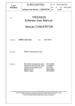
transmission to the GEOs, which then re-transmits the data on the GPS L1 frequency.
Figure 1: The SBAS Concept
Reference
1
2
3
4
5
6
7
8
9
10
Description
Geo satellite
GPS satellite constellation
L1 and L2
C1 and C2
GPS user
Integrity data, differential corrections and ranging control
Reference station
Master station
Integrity data, differential corrections, time control and status
Ground uplink subsystem
Euro-3 and Enclosures User Manual Rev 3
17
Chapter 1
1.4
Introduction
EuroPak-3 and EuroPak-3T Enclosures
The EuroPak-3 and EuroPak-3T provide a hardware interface between your equipment and the NovAtel Euro3 GPSCard. Each is a rugged enclosure that provides protection against adverse environments. It has DB-9
connectors to access data and status signals.
The EuroPak-3 and EuroPak-3T offer the following features:
•
•
•
•
•
•
A mounting enclosure with a PCB interconnect back plane
Three serial ports provided on three DB-9P connectors
One Universal Serial Bus (USB) port (shares COM1 DB-9P connector)
Auxiliary status and synchronization signals
GPS antenna and input power ports
Indicators to provide power and communication status
The EuroPak-3 also offers this feature:
•
An external oscillator port (input only)
The EuroPak-3T also offers this feature:
•
An external oscillator port (output only)
The following accessories are included with the EuroPak-3 and EuroPak-3T:
•
•
•
•
•
1 12V power cable
1 I/O cable
1 null modem serial cable
1 straight through serial cable
A CD containing NovAtel’s GPS PC utilities and product documentation
For technical specifications on the EuroPak-3 and EuroPak-3T, please see Appendix A, Technical Specifications
starting on Page 144.
Figure 2: EuroPak-3 and EuroPak-3T Enclosures
Figure 3: EuroPak-3 and EuroPak-3T Rear Panel
18
Euro-3 and Enclosures User Manual Rev 3
Introduction
1.5
Chapter 1
Euro-3 Features
The Euro-3 has been designed with the following features:
• 32 channel “all-in-view” parallel tracking
• cross-correlation detection channel
• bit synchronization check channel
• constant post-correlation noise floor measurement channel
• Fast reacquisition
• Fully field-upgradeable firmware
• Low power consumption
• 1 Hz raw data and position output rates
At a minimum, the following models are available for each receiver:
•
L1L2GEO
•
GRCT
•
MEDLL
•
L1L2GEOT
•
GRC
•
MEDLLT
Those models with dual-frequency capabilities make the following possible:
• Longer baselines in differential positioning mode, due to the reduction of atmospheric errors
• Enhanced positioning precision due to the additional measurements
• Support for L1 and L2 GPS signal processing
•
Support for L1 GEO signal processing
•
Ability to significantly reduce multipath effects on GPS data (MEDLL, see Section 1.5.2 below)
•
GPS signal quality monitoring (SQM) functionality, see Section 1.5.5 on Page 20
•
Digital pulse blanking for the L2 signal
The majority of these features are discussed further in the following sections.
1.5.1
GEO Processing
Specific channels in the Euro-3 have the capability to receive and process the SBAS signal provided by GEOs.
The signal is in-band at L1 and is identified through the use of SBAS-specific PRN numbers. The SBAS
message is decoded and separated into its various components. The SBAS message and associated
pseudorange are provided as an output.
1.5.2
Multipath Reduction
The Euro-3 with the MEDLL option can achieve a high level of multipath reduction. NovAtel has developed a
multipath elimination technology that approaches the theoretical limits of multipath-free GPS signal reception.
This patented technology, known as Multipath Estimating Delay-Lock-Loop (MEDLL), uses a combination of
hardware and software techniques, which together are capable of reducing the combined effects of pseudorange
and carrier-phase multipath errors by as much as 90% compared to a system using Narrow Correlator tracking
technology alone.
1.5.2.1
Optional MEDLL Technology
MEDLL technology takes advantage of NovAtel's parallel channel Narrow Correlator sampling techniques.
MEDLL uses a proprietary coupled correlator sampling technique combined with "maximum likelihood
estimation" techniques to break down the received signals into direct path and reflected path components.
MEDLL determines the amplitude, delay, and phase angle of both the direct and multipath signals and analyses
the signal with the least delay to determine the direct path. All other signals with greater delay are considered to
be multipath components and are removed.
MEDLL is running as a monitoring system only and does not close the delay lock loop (DLL).
Euro-3 and Enclosures User Manual Rev 3
19
Chapter 1
1.5.3
Introduction
Cross-Correlation Detection Channel
NovAtel’s patent-pending SafeTrak technology is also featured in Euro-3-based products.
The receiver tracks a satellite by replicating the satellite's PRN code and aligning it with the received PRN
code. Cross-correlation happens when the receiver is tracking a certain PRN code with an incorrectly replicated
PRN code. This is due to the receiver tracking a minor, rather than the required major, correlation peak. The
Euro-3 performs a cross-correlation check on channels tracking at low C/No values. The cross-correlation
channel aligns its code phase with that of the tracking channel under test. An initial power check between the
two channels is made to check alignment and the cross-correlation channel shifts its code phase repeatedly to
measure the power. If at any point it determines that the cross-correlation power is within a certain level of the
initial power, the channel under test is tracking one of the minor cross-correlation peaks. The tracking channel
then re-acquires the satellite to remove the cross-correlation error.
1.5.4
Bit Synchronization
Bit synchronization identifies the location of navigation bit edges with respect to the 1 ms C/A-code epochs.
Bit edge detection is based on observing the sign transition between successive 1 ms accumulations that are
aligned with the received C/A-code epochs. The bit synchronization is verified by an additional hardware
channel and software steering. This additional hardware is configured to generate a stream of 1 ms
accumulations until sufficient data has been collected to perform the test. The tracking channel is forced to reacquire if the results of this test confirms a bit alignment error.
1.5.5
Signal Quality Monitoring
Signal Quality Monitoring (SQM) technology is used to monitor GPS signals in space for anomalous behavior.
To do this, the Euro-3 outputs accumulations at the specified correlation function values. It collects accurate
accumulation values and outputs them in a timely fashion. The Euro-3 hardware is capable of tracking the
correlation function at multiple correlation locations. See also the ALLSQMIINFO and ALLSQMQINFO logs
starting on Page 101 for more information about correlator locations.
1.5.6
Digital Pulse Blanking
Digital pulse blanking involves removing or attenuating pulses in the RF signal that exceed a specified level.
The Euro-3 provides digital pulse blanking for the L2 signal path only.
Use the PULSEBLANKING command to enable/disable L2 pulse blanking or to control its sensitivity, see
Page 83.
1.6
Euro-3 GPSCard
The Euro-3 card consists of a radio frequency (RF) and a digital electronics section.
In addition to the Euro-3, a GPS receiver system typically contains three other major components:
•
A GPS antenna (and optional LNA power supply)
•
A power supply
Data communications equipment
1.6.1
Radio Frequency (RF) Section
The receiver obtains a filtered and amplified GPS signal from the antenna via the coaxial cable. The RF section
performs the translation from the incoming RF signal to an IF signal usable by the digital section. It also
supplies power to the active antenna’s LNA through the coaxial cable while maintaining isolation between the
DC and RF paths. The RF section can reject a high level of potential interference (for example, MSAT,
20
Euro-3 and Enclosures User Manual Rev 3
Introduction
Chapter 1
Inmarsat, cellular phone, and TV sub-harmonic signals).
1.6.2
Digital Electronics Section
The digital section of the receiver, receives a down-converted, amplified GPS signal which it digitizes and
processes to obtain a GPS solution (position, velocity and time). The digital section consists of an analog-todigital converter, a 32-bit micro processor, memory, control and configuration logic, signal processing
circuitry, serial peripheral devices, and supporting circuitry.
The digital section performs the translations and calculations necessary to convert the IF analog signals into
usable position and status information. It also handles all I/O functions, including the auxiliary strobe signals,
which are described in detail in Section 2.3.1 on Page 29. For input and output levels please see Appendix A,
Technical Specifications starting on Page 144 for the Euro-3.
1.6.3
GPS Antenna
The purpose of the GPS antenna is to receive the GPS/GEO signals in space, to band limit the signal, and to
amplify the signal for transmission to the card. An active GPS antenna with an LNA is required for the receiver
to function properly. NovAtel’s active antennas are recommended.
Power for the antenna LNA is supplied by the receiver.
1.6.4
Principal Power Supply
A single external power supply capable of delivering 10 W is necessary to operate the receiver. See Page 146
for details.
WARNING:
1.6.5
If the voltage supplied is below the minimum specification, the receiver will suspend
operation. If the voltage supplied is above the maximum specification, the receiver may
be permanently damaged, voiding your warranty.
Data Communications Equipment
A PC or other data communications equipment is necessary to communicate with the receiver and, if desired, to
store data generated by the receiver.
Euro-3 and Enclosures User Manual Rev 3
21
Chapter 2
Installation
This chapter contains instructions and tips to set up your NovAtel receiver to create a GPS receiver system.
WARNING: Complete all installation instructions before applying power to the receiver.
2.1
Additional Equipment Required
In order for the receiver to perform optimally, the following additional equipment is required:
•
•
•
•
•
•
•
An interface for power, communications, and other signals and an enclosure to protect against the
environment (if your receiver has been purchased as a GPSCard without an enclosure)
An active GPS antenna
A quality coaxial cable (and interconnect adapter cable as necessary)
Data communications equipment capable of serial communications
A serial cable (if not included with the receiver)
A power supply
A power cable (if not included with the receiver)
CAUTION:
2.1.1
When the Euro-3 receiver is installed in a permanent location, such as in a building,
it should be protected by a lightening protection device according to local building
codes. See also Warranty Policy on Page 13.
Selecting a GPS Antenna
An active antenna is required because its low-noise amplifier (LNA) boosts the power of the incoming signal to
compensate for the line loss between the antenna and the receiver.
NovAtel offers a variety of single and dual-frequency GPS antenna models, as indicated in the table below. All
include band-pass filtering and an LNA. The GPS antenna you choose will depend on your particular
application. Each of these models offer exceptional phase-center stability as well as a significant measure of
immunity against multipath interference. Each one has an environmentally-sealed radome.
Table 1: NovAtel GPS Antenna Models
Models
2.1.2
Frequencies Supported
701
L1 only
702, 532, 533
L1 and L2
Choosing a Coaxial Cable
An appropriate coaxial cable is one that is matched to the impedance of the antenna and receiver being used (50
ohms), and whose line loss does not exceed 10.0 dB. If the line loss limit is exceeded, excessive signal
degradation will occur and the receiver may not meet its performance specifications. NovAtel offers a variety
of coaxial cables to meet your GPS antenna interconnection requirements, including:
•
5, 15, or 30 m antenna cables with TNC male connectors on both ends (NovAtel part numbers C006,
C016 and C032 respectively)
Your local NovAtel dealer can advise you about your specific configuration. Should your application require
23
Euro-3 and Enclosures User Manual Rev 3
Chapter 2
Installation
the use of cable longer than 30 m you will find the application note RF Equipment Selection and Installation at
our Web site, www.novatel.com, or you may obtain it from NovAtel Customer Support directly.
High-quality coaxial cables should be used because a mismatch in impedance, possible with lower quality
cable, produces reflections in the cable that increase signal loss. Though it is possible to use other high-quality
antenna cables, the performance specifications of the Euro-3-based receivers are warranted only when used
with NovAtel-supplied accessories.
2.1.3
Power Supply Requirements
This section contains information about the requirements for the input power to the receiver. See Page 146 for
more power supply specifications.
WARNING:
If the voltage supplied is below the minimum specification, the receiver will suspend
operation. If the voltage supplied is above the maximum specification, the receiver
may be permanently damaged, voiding your warranty.
The Euro-3 GPSCard contains a DC to DC converter that is very tolerant to noise and ripple at its input. A
tightly regulated input supply to the card is not required, as long as it falls within the given input range. The
power supply used should be capable of 10 W. The voltage input range for the Euro-3 GPSCard is +4.5 to +18
VDC.
The receivers are designed to prevent internal damage when subjected to a reverse polarity power connection.
They also provide protection from short over voltage events. It is recommended that appropriate fuses or
current limiting be incorporated as a safety precaution on all power lines used. Use a sufficient gauge of wire to
ensure that the voltage at the connector is within the GPSCard’s requirements.
2.1.3.1
EuroPak-3 and EuroPak-3T Enclosures
The EuroPak-3 and EuroPak-3T are supplied with a 12 V power cable with a built-in slow-blow fuse for use
with a standard 12 VDC power outlet.
If a different supply is desired, the input range required is +9 to +18 VDC for the EuroPak-3 and +11 to +18
VDC for the EuroPak-3T. The type of connector required to mate with the receiver’s power connector is a 4-pin
LEMO socket connector labelled PWR. The supply should be capable of 10 W for the EuroPak-3 and 15W for
the EuroPak-3T. See Appendix D, Replacement Parts on Page 164 for LEMO connector part numbers.
2.2
Installation Overview
Once you have selected the appropriate equipment, complete the following steps to set up and begin using your
NovAtel GPS receiver.
1.
2.
3.
4.
5.
If your receiver has been provided as a GPSCard without an enclosure, install the card in an enclosure
with a wiring harness, as described in Section 2.2.1 on Page 25.
Mount the GPS antenna to a secure, stable structure, as described in Section 2.2.2 on Page 27.
Connect the GPS antenna to the receiver using an antenna RF cable, using the information given in
Section 2.2.3 on Page 27.
Connect the receiver to a PC or other data communications equipment by following the information given
in Section 2.2.4 on Page 28.
Apply power to the receiver, as described in Section 2.2.5 on Page 28.
Figure 4 on the next page shows a typical set up for an enclosed receiver.
24
Euro-3 and Enclosures User Manual Rev 3
Installation
Chapter 2
1
2
4
6
5
Figure 4: Typical Receiver Installation
Reference
1
2
3
4
5
6
2.2.1
Description
Receiver
GPSAntenna Model 702 or 701
RF Antenna Cable
12V Power Cable
Null Modem Data Cable (shown) or USB Cable
Data Communications Equipment
Installing a GPSCard in a Wiring Harness and Enclosure
To install a GPSCard, begin with the following:
1.
2.
3.
Ensure you are taking the necessary precautions against ESD, as described in Section 2.2.1.1 below.
Mount the GPSCard in a secure enclosure to reduce environmental exposure and RF interference, as
described in Section 2.2.1.2 on Page 26.
Prepare a wiring harness to interface to the receiver’s data, status, and power signals using the information
given in Section 2.2.1.3 on Page 26.
2.2.1.1
Electrostatic Discharge (ESD) Precautions
Electrostatic discharge is a leading cause of failure of electronic equipment components and printed circuit
boards containing ESD-sensitive devices and components. It is imperative that ESD precautions be followed
when handling or installing a GPSCard. Please see Appendix B, Electrostatic Discharge Control (ESD)
Practices starting on Page 161 for more information about ESD precautions.
Leave the GPSCard in its static-shielding bag or clamshell when not connected in its normal operating
environment. When removing the GPSCard from the ESD protection, follow accepted standard anti-static
practices. Failure to do so may cause damage to the GPSCard and void the warranty.
Euro-3 and Enclosures User Manual Rev 3
25
Chapter 2
Installation
When you remove the GPSCard from the original packing box, it is recommended that you save the box and
ESD protection for future storage or shipment purposes.
WARNING!
Remember:
•
•
•
•
•
2.2.1.2
Always wear a properly grounded anti-static wrist strap when handling the GPSCard.
Always hold the GPSCard by its corners or the RF shield, and avoid direct contact with any of
the components.
Do not let the GPSCard come in contact with clothing at any time because the grounding strap
cannot dissipate static charges from fabrics.
Failure to follow accepted ESD handling practices could cause damage to the GPSCard.
Warranty may be voided if equipment is damaged by ESD.
Mounting the Printed Circuit Board
The Euro-3 GPSCards are OEM products and therefore the printed circuit board is provided without a housing
structure. This allows flexibility in creating a mounting environment to suit particular product and marketing
requirements. The mounting and enclosure should provide the following:
•
•
•
•
•
mounting of external connectors
protection from hostile physical environments (for example, rain, snow, sand, salt, water, extreme
temperatures)
electromagnetic shielding to protect from hostile RF environments (for example, nearby transmitters)
electromagnetic shielding so that the final product itself conforms to RF emissions specifications
protection from ESD (see Appendix B, Electrostatic Discharge Control (ESD) Practices starting on
Page 161)
The GPSCard can be held in place by screws. Please see Figure 21, Euro-3 Board Dimensions on Page 145 for
mechanical drawings.
2.2.1.3
Preparing the Data, Signal & Power Harness
The wiring harness provides the following interconnect functions:
•
•
•
•
access to the serial communications ports
access to input and output timing strobes
power input(s)
access to control signals
For all GPSCards, the power, status, and data inputs and outputs are accessed from a single connector.
Therefore, the harness must be designed to mate with this connector.
As shown in Figure 5 on Page 27, the Euro-3 uses a 160-pin five-row male connector with 0.1” spacing for the
data, power, and status signals. The pin out for this connector is specified after Figure 22 on Page 148. The RF
connector is an SMB male jack.
26
Euro-3 and Enclosures User Manual Rev 3
Installation
Chapter 2
4
3
2
1
Figure 5: Euro-3 Connector and Indicator Locations
.Reference
1
2
3
4
2.2.2
Description
Power, signal and data connector P1200 (male, 160-pin, DIN 41612, right-angle)
that connects to user-supplied interface
LED status indicator
External oscillator input (SMB straight male jack)
RF signal input and LNA power output (SMB straight male jack)
Mounting the GPS Antenna
Once the GPSCard is installed in a wiring harness and enclosure, the antenna to be used with the receiver must
be mounted. The GPS receiver has been designed to operate with any of the NovAtel single-frequency or dualfrequency GPS antenna models. See Section 2.1.1 on Page 23 for more information.
When installing the antenna system:
•
•
•
2.2.3
Choose an antenna location that has a clear view of the sky so that each satellite above the horizon can
be tracked without obstruction. For more information about multipath, please refer to the Knowledge
and Learning page in the Support section of our Web site at www.novatel.com.
Choose an antenna location that provides low multipath conditions for the received signal. For
example, in the middle of a flat roof. The edge of a roof with visibility to a parking lot is a high
multipath environment.
Mount the antenna on a secure, stable structure capable of safe operation in the specific environment.
Connecting the Antenna to the Receiver
Connect the antenna to the receiver using high-quality coaxial cable, as discussed in Section 2.1.2 on Page 23.
The EuroPak-3 and EuroPak-3T provide a TNC female connector, which can be connected to the antenna
directly with any of NovAtel’s coaxial cables. For the GPSCards, an interconnect adapter cable is required to
convert the TNC male end of the coaxial cable to the card’s SMB straight male jack RF input connector. The
location of the RF connector for the GPSCard is shown in Figure 5 above.
Euro-3 and Enclosures User Manual Rev 3
27
Chapter 2
2.2.4
Installation
Connecting Data Communications Equipment
In order to communicate with the receiver by sending commands and obtaining logs, a connection to some
form of data communications equipment is required, usually a PC computer. The default configuration
available for each of the receiver types is given in the table below. See Page 147 of Appendix A for data
connection details.
Table 2: Default Serial Port Configurations
Receiver
COM1
COM2
COM3
USB1
RS-232/RS-422
RS-232/RS-422
RS-232/RS-422
USB 1.1
EuroPak-3
RS-232
RS-232
RS-232
USB 1.1
EuroPak-3T
RS-232
RS-232
RS-232
USB 1.1
Euro-3
Each port may support some, or all, of the following signals:
•
•
•
•
•
Clear To Send (CTS)
Transmitted Data (TXD)
Request To Send (RTS)
Received Data (RXD)
Data Carrier Detect (DCD)
Extra control lines are provided on COM2 for use with modems or other differential correction data links.
The EuroPak-3 and EuroPak-3T enclosures are Data Terminal Equipment (DTE) so that TXD, RTS and DTR
are outputs while RXD, CTS and DCD are inputs. A null modem cable is required to connect to another DTE
like a terminal or a PC.
The RS-232, or RS-422, port settings (bit rate, parity, and so on) are software-configurable. These are further
described in Chapter 3, Operation on Page 38. See Table 60, EuroPak-3/3T Serial Port Pin-Out Descriptions
on Page 152 for further information about data communications characteristics.
The receiver supports USB communication by connecting COM1 on the receiver to a USB port on the data
communications equipment using the USB cable provided.
Figure 6: USB Cable Connection
You must now install NovAtel's USB driver and Virtual Serial Port Utility. See Section 2.3.6 starting on Page
31 for details on the USB driver and utility installations.
2.2.5
Applying Power to the Receiver
Connect the power supply, set to the voltage given in Section 2.1.3 on Page 24, to the wiring harness created
previously.
For a EuroPak-3 and EuroPak-3T enclosure, connect the power supply to the PWR port.
28
Euro-3 and Enclosures User Manual Rev 3
Installation
2.3
Chapter 2
Additional Features and Information
This section contains information about the additional features of the Euro-3-based receivers, which may affect
the overall design of your receiver system.
2.3.1
Strobes
A set of inputs and outputs that provide status and synchronization signals are provided on the Euro-3. These
signals are referred to as strobes. As shown in Table 3 below, not all strobe signals are provided on all receivers.
However, for those products for which strobes are available, you may want to design your installation to
include support for these signals.
The Euro-3 has 9 TTL-compatible I/O strobe lines. See Figure 21, Euro-3 Board Dimensions on Page 145.
The EuroPak-3 and EuroPak-3T enclosures provide strobe signals at their I/O port, as described in Table 61 on
Page 153.
Strobe signals include an input and several outputs as described below:
•
•
•
•
•
•
•
•
Mark Input (Event1)
A pulse on this input triggers certain logs to be generated.
(see Section 4.2.2, Log Triggers on Page 44).
Measure Output (MSR)
Falling edge is synchronized with internal GPS
measurements.
Pulse Per Second Output (PPS)
A pulse for which the trailing edge is synchronized with GPS
time.
Clock Model Valid Output (PV)
High when good GPS time solution.
Error Output (ERROR)
High when a receiver hardware failure is detected.
LED Red Output (STATUS_RED)
Hardware failure when on or pulsing.
LED Green Output (STATUS_GREEN) Normal operation when pulsing at 1 Hz.
Variable Frequency (VARF)
Variable output range from 0 to 20 MHz.
See the Strobe Electrical Specifications section starting on Page 147, for further information about the strobe
signal characteristics.
Table 3: Available Strobe Signals on Receivers
Signal
2.3.2
EVENT1
MSR
PPS
PV
ERROR
STATUS
_RED
STATUS
_GREEN
VARF
Euro-3
Pin B24
Pin B23
Pin B22
Pin B25
Pin B15
Pin B5
Pin B6
Pin B21
EuroPak-3 and
EuroPak-3T
I/O port,
pin 4
I/O port,
pin 3
I/O port,
pin 2
I/O port,
pin 5
I/O port,
pin 8
Not
available
Not
available
I/O port,
pin 1
Status Indicators
The Euro-3 receivers have LED indicators that provide the status of the receiver. The GPSCards have a single
indicator, which is shown in Figure 5 on Page 27 for the Euro-3. The LED blinks green on and off at
approximately 1 Hz to indicate normal operation. If the indicator is red, then the receiver is not working
properly. The operation of this indicator is further described in Section 8.5 on Page 142.
Euro-3 and Enclosures User Manual Rev 3
29
Chapter 2
Installation
The EuroPak-3 and EuroPak-3T provide the status indicators shown in Table 4.
Table 4: EuroPak-3 and EuroPak-3T Status Indicators
Indicator
COM1
COM2
AUX
PWR
2.3.3
Indicator Color
Green
Red
Green
Red
Green
Status
Data is being transmitted from COM1
Data is being received on COM1
Data is being transmitted from COM2
Data is being received on COM2
Data is being transmitted from COM3
Red
Data is being received on COM3
Red
The receiver is powered
External Oscillator
For certain applications requiring greater precision than what is possible using the Euro-3’s on-board 20 MHz,
voltage-controlled, temperature-compensated crystal oscillator (VCTCXO), you may wish to connect the Euro3 to an external, high-stability oscillator. The external oscillator can be either 5 MHz or 10 MHz. See the
External Oscillator Input section on Page 146 for the full specifications of this signal.
If you do not use the EXTERNALCLOCK command to specify a clock type, see Page 73, its default is
DISABLE. This means the external clock input is off and the board is using the on-board VCTCXO.
Installation consists of connecting a cable from the external oscillator to the Euro-3’s external oscillator input
connector.
For the EuroPak-3 and EuroPak-3T the BNC external oscillator port, labeled OSC, is used for input and output
signals respectively. See Figure 3 on Page 18.
For the Euro-3, an SMB straight male jack connector is used, as shown in Figure 5 on Page 27. The receiver
does not have to be powered down during this procedure. If you are handling the Euro-3 directly, anti-static
practices must be observed.
Once an external oscillator has been connected, the EXTERNALCLOCK command, see Page 73, must be
issued to define the clock model (for example, cesium, rubidium or ovenized crystal) and to set the input clock
frequency.
2.3.4
External Antenna LNA Power (Euro-3 GPSCard Only)
For the Euro-3 it is possible to supply power to the LNA of an active antenna either from the antenna port of the
GPSCard itself or from an external source. The internal antenna power supply of the GPSCards can produce +5
VDC at up to 150 mA. This meets the needs of NovAtel’s dual-frequency GPS antennas, so, in most cases, an
additional LNA power supply is not required.
If a different antenna is used whose LNA requires voltage capacity beyond what the receiver can produce, then
the external LNA power option must be utilized. This simply requires setting a voltage supply between +8 and
+30 VDC, 150 mA maximum, and connecting it to pin 40 of the 40-pin connector on the Euro-3. See also
Appendix A, RF Input and LNA Power on Page 146.
In either case, the LNA power is fed to the antenna through the same coaxial cable used for the RF signals. The
internal LNA power source should be disabled using the ANTENNAPOWER command. Refer to Volume 2 of
this manual for more information about this command.
30
Euro-3 and Enclosures User Manual Rev 3
Installation
Chapter 2
CAUTION
No warranty is made that the receiver meets its performance specifications if a non-NovAtel antenna is used.
2.3.5
Mounting Bracket (EuroPak-3 and EuroPak-3T Only)
Along with the EuroPak-3 and EuroPak-3T enclosures, mounting kits have been provided to facilitate
mounting the receivers to a surface. This section provides information about how to mount the receivers.
The mounting kits are not designed for use in high-dynamics or high-vibration environments. Contact
NovAtel Customer Support if your application requires the EuroPak-3 and EuroPak-3T to be mounted in
these types of environments.
To install the mounting bracket provided with the EuroPak-3 and EuroPak-3T, refer to the instructions provided
with the mounting kit. Page 159 provides the dimension information for the bracket.
2.3.6
Installing the USB Driver and the USB Virtual Serial Port Utility
Once the EuroPak is connected to the PC, and power supply, install NovAtel's USB Driver and NovAtel’s USB
Virtual Serial Port utility by advancing through the following steps:
1. Unzip the ZIP file NovAtel_3000.zip, on the CD provided, to a local directory (for example,
C:\NovAtel_3000) on the PC file system.
2. Power up the EuroPak. The PC detects the new USB device connected to it, and prompts "Found
New Hardware" (OEM4 Schwarz). The "Found New Hardware Wizard" starts. Install the USB
driver (NovAtel GPS Receiver) by advancing through the following steps:
3. Select "No, not this time".
Euro-3 and Enclosures User Manual Rev 3
31
Chapter 2
Installation
4. Click on the "Next" button.
5. Select "Install from a list or specific location (Advanced)".
6. Click on the "Next" button.
7. Select "Search for the best driver in these locations.".
8. Check the "Include this location in the search:" check box, and click on the ‘Browse’ button to
32
Euro-3 and Enclosures User Manual Rev 3
Installation
Chapter 2
browse for the location of the NovAtel USB driver.
9. Click on the "Next" button.
The Found New Hardware Wizard displays a progress window:
10. Click on the "Continue Anyway" button, if the message below appears:
The installation process continues.
Euro-3 and Enclosures User Manual Rev 3
33
Chapter 2
Installation
11. Click on the "Continue Anyway" button, if the message below appears:
12. Click on the Finish button:
When the system detects the NovAtel USB Virtual Serial Port, the "Found New Hardware Wizard"
starts.
13. Install the driver for the NovAtel USB Virtual Serial Port by advancing through the following
steps:
34
Euro-3 and Enclosures User Manual Rev 3
Installation
Chapter 2
14. Select "No, not this time" and click on the "Next" button.
15. Select "Install from a list or specific location (Advanced)"and click on the "Next" button.
Euro-3 and Enclosures User Manual Rev 3
35
Chapter 2
Installation
16. Select "Search for the best driver in these locations".
17. Check the "Include this location in the search:" check box, and click on the ‘Browse’ button to
browse for the location of the NovAtel USB driver and click on the "Next" button.
18. The Found New Hardware Wizard displays a progress window:
36
Euro-3 and Enclosures User Manual Rev 3
Installation
Chapter 2
19. Click on the "Continue Anyway" button, if the message below appears:
20. Click on the Finish button to complete the installation:
Euro-3 and Enclosures User Manual Rev 3
37
Chapter 3
Operation
Before operating the receiver for the first time, ensure that you have followed the installation instructions in
Chapter 2. From here on, it will be assumed that testing and operation of the receiver will be performed while
using a personal computer (PC), which allows the greatest ease and versatility.
3.1
Pre-Start Check List
Before turning on power to the receiver, ensure that all of the following conditions have been met:
•
The antenna is properly installed, powered through coaxial cable, and connected.
•
The PC is properly connected using a serial cable, and its communications protocol has been
configured to match that of the receiver.
Supply power to the receiver only after all of the above checks have been made. Note that the warm-up process
may take several minutes, depending on ambient temperature.
3.2
Boot-up
The receiver’s firmware resides in non-volatile memory. After supplying power to the unit, wait a few
moments for the self-boot to complete, after which the receiver will be ready for command input.
The initial start-up indicator lets you know that the receiver's main serial port is ready to communicate:
•
Your PC will display the following prompt, indicating you are connected through the COM1 port:
[COM1]
The receiver has 4 modes of operation including power-up mode:
•
Power-Up
•
Operational
•
Fault
•
Maintenance
The receiver is in power-up mode after applying power. While in this mode, all sections of the receivers (for
example, encoders, correlators, and so on) are disabled, except for the clock generators and microprocessor
interface. During this mode, SW is transferred from Flash to RAM, the 32-bit CRC is verified on the SW load
and the Initiated Built In Test (IBIT) is exercised to determine whether the receiver is usable. This mode ends
when the functional blocks of the receiver have been enabled, initialized and the IBIT has been successfully
executed.
The receiver is in operational mode following power-up mode and before a fault is discovered by the
Continuous Built In Test (CBIT). The fault mode is entered when the CBIT detects an error condition.
The receiver is in maintenance mode when it is loading software. Maintenance mode can only be entered via
the Power-up mode.
Once you are connected, commands can be entered as explained in Section 3.3.
Euro-3 and Enclosures User Manual Rev 3
38
Operation
3.3
Chapter 3
Communicating with the Receiver
Communicating with the receiver is accomplished by issuing commands, either by an operator or a script, at the
[COM1] prompt displayed by the PC.
The commands and logs used by the receiver, as well as the fields within them, follow specific formats, which
are specified in Chapter 4. The valid commands, which are used to control the operation and data logging of
the receiver, are specified in Chapter 5. Chapter 6 provides details on the data logs that can be requested from
the receiver. It is to your advantage to become thoroughly familiar with Chapters 4 through 6 of this manual to
ensure maximum utilization of the receiver's capabilities.
Euro-3 and Enclosures User Manual Rev 3
39
Chapter 4
Using Commands and Logs
Chapter 5 and Chapter 6 provide the details of the commands and logs used to communicate with the receiver.
The sections below give information about using these messages, including the formats they can take and the
responses they may provide.
4.1
Entering Commands
The receiver is capable of responding to many different input commands. The commands offer a wide range of
flexibility and can be used to control the following:
•
The overall status of the receiver
•
Input and output functions
•
Configuration of a specific channel of the receiver
The following rules apply when entering commands and logs:
1. You must enter commands in Abbreviated ASCII format. The name of the command and its
parameters are entered.
2. The commands are not case sensitive. For example:
FIX POSITION or fix position
3. At the end of a command or command string, press <ENTER>.
4.1.1
Command Settings on Power-Up
When the receiver is first powered up, or after an FRESET command, all commands revert to the factory
default settings.
The FRESET command causes all previously stored information saved to non-volatile memory to be
erased. This command is detailed in Section 5.2.14 on Page 77.
4.1.1.1
Factory Defaults
The factory defaults for the Euro-3 L1L2GEO and MEDLL models are:
ANTENNAPOWER ON
CHANCONFIG 14GPS4GEO_1 (this becomes 8GPS1GEO_1M for the MEDLL model)
CLOCKADJUST ENABLE
COM COM1 9600 N 8 1 N OFF ON
COM COM2 9600 N 8 1 N OFF ON
COM COM3 9600 N 8 1 N OFF ON
DLLBW CA 0.2
DLLBW PY 0.2
EXTERNALCLOCK DISABLE (this becomes OCXO 10MHz for the EuroPak-3T)
PLLBW CA 15
PLLBW PY 0.2
ECUTOFF 0
FIX NONE
PULSEBLANKING L2 15
Euro-3 and Enclosures User Manual Rev 3
40
Using Commands and Logs
Chapter 4
THRESHOLD 36 20 36 CA GPS
THRESHOLD 33 28 36 CA WAAS
The defaults are the same for other models except for:
GRC:
ANTENNAPOWER OFF
GRCT:
ANTENNAPOWER OFF
EXTERNALCLOCK OCXO 10MHZ
CLOCKADJUST DISABLE
L1L2GEOT and MEDLLT:
CHANCONFIG 14GPS4GEO_1 (this becomes 8GPS1GEO_1M for the MEDLLT model)
EXTERNALCLOCK OCXO 10MHZ
CLOCKADJUST DISABLE
PLLBW CA 3
4.1.2
Determining the Current Command Settings
To determine the current command settings of a receiver, request a RXCOMMANDS log, which is described in
Section 6.3.15 on Page 120. This will provide a listing of all commands and their parameter settings. This log
provides the most complete information about receiver configuration.
For some commands, including COM and LOG, multiple parameter sets can exist. For example, the LOG
command can be entered with one set of parameters to enable logging of the PSRPOS log. It can then be
entered again with a second set of parameters to configure the receiver to capture the RANGE log. When the
LOG command is entered the second time, the new parameter set does not overwrite the first, it exists in
addition to the first set.
4.1.3
Response Formats
The format of the response is dependent on the format of the input command. If the command is input as
Abbreviated ASCII, the output will be Abbreviated ASCII.
Abbreviated ASCII
A leading < followed by the response string, like the example below:
Euro-3 and Enclosures User Manual Rev 3
41
Chapter 4
Using Commands and Logs
<OK
ASCII
Full header with the message name being identical except ending in an 'R' (for response). The body of the
message consists of a 40 character string for the response string.
Example:
#PSRPOSA,COM1,0,43.0,FINESTEERING,265,320943.000,00840000,0000,33331;SOL_COMPUTED,
SINGLE,51.11638529847,-114.03825624352,1045.2359,0.0000,WGS84,1.5908,1.4096,2.3924,"",
0.000,0.000,10,8,0,0,0,0,0,0*84ea7b68
Binary
Similar to an ASCII response except that it follows the binary protocols:
•
Binary header with message type set to response value (for example, 0x82), see Field 6 in
Table 8, Binary Message Header Structure on Page 49.
•
ENUM response ID, see Table 5, Response Messages on Page 43.
String containing the ASCII response to match the ENUM response ID above (for example, 0x4F04B = OK)
4.1.4
Response Messages
The receiver is capable of outputting several responses for various conditions. Most of these responses are error
messages to indicate when something is not correct. Table 5 on Page 43 outlines the various response strings
and message IDs.
42
Euro-3 and Enclosures User Manual Rev 3
Using Commands and Logs
Chapter 4
Table 5: Response Messages
String
ID
Meaning
OK
1
Command was received correctly
NOT ENOUGH RESOURCES IN SYSTEM
3
The request has exceeded a limit (for example, the
maximum number of logs are being generated)
DATA PACKET DOESN’T VERIFY
4
Data packet is not verified
COMMAND FAILED ON RECEIVER
5
Command did not succeed in accomplishing requested
task
INVALID MESSAGE ID
6
The input message ID is not valid
INVALID MESSAGE FIELD = X
7
Field x of the input message is not correct
MESSAGE MISSING FIELD
9
A field is missing from the input message
ARRAY SIZE FOR FIELD X EXCEEDS MAX 10
Field x contains more array elements than allowed
PARAMETER X IS OUT OF RANGE
11
Field x of the input message is outside the acceptable
limits
TRIGGER X NOT VALID FOR THIS LOG
14
Input trigger x is not valid for this type of log
NO VALID AUTH CODE FOR THAT
MODEL
19
The model attached to the authcode is not valid
CHANNEL IS INVALID
20
The selected log cannot be output at the specified rate
REQUESTED RATE IS INVALID
21
The requested rate is invalid
CHANNELS LOCKED DUE TO ERROR
23
Channels are locked due to error
INJECTED TIME INVALID
24
Injected time is invalid
COM PORT NOT SUPPORTED
25
The COM port is not supported
MESSAGE IS INCORRECT
26
The message is invalid
INVALID PRN
27
The PRN is invalid
MESSAGE TIMED OUT
31
The message has timed out
UNKNOWN COM PORT REQUESTED
33
Unknown COM port requested
HEX STRING NOT FORMATTED
CORRECTLY
34
Hex string not formatted correctly
INVALID BAUD RATE
35
The baud rate is invalid
MESSAGE IS INVALID FOR THIS MODEL
36
This message is invalid for this model of receiver
COMMAND ONLY VALID IF IN NVM FAIL
MODE
40
Command is only valid if NVM is in fail mode
INVALID OFFSET
41
The offset is invalid
MAX NUMBER OF USER MESSAGES
REACHED
78
The maximum number of user messages allowed has
been reached
GPS PRECISE TIME IS ALREADY KNOWN
84
GPS precise time is already known
Euro-3 and Enclosures User Manual Rev 3
43
Chapter 4
4.2
Using Commands and Logs
Logging Data
You can control how the receiver logs data by using the LOG command given on Page 78. A field within this
command allows you to specify which data log from Chapter 6 to capture. There are some things to be noted
however:
1. The receiver can handle 20 logs at a time. If you attempt to log more than 20 logs at a time, the
receiver will respond with the error message:
Not enough resources in system
2. Maximum flexibility for logging data is provided to you by these logs. You are cautioned,
however, to recognize that each log requested requires additional CPU time and memory buffer
space. Too many logs may result in lost data and degraded CPU performance. Receiver overload
can be monitored using the idle-time field and the buffer overrun bits of the Receiver Status field,
which are both found in any log header.
When a log is generated, it is sent to the serial port specified by the port parameter in the entered LOG
command.
4.2.1
Log Types
The receiver is capable of generating many different logs. These logs are divided into the following three types:
4.2.2
•
Synchronous
The data contained in synchronous logs is generated on a regular schedule.
•
Asynchronous
The data in asynchronous logs is generated at irregular intervals. If these logs
were collected on a regular schedule, there would be a delay in capturing the
new data. The result is that changes to the data are not captured the moment
they are available.
•
Polled
The data in polled logs is generated only when requested. Typically the data
in these logs, such as configuration settings, does not change.
Log Triggers
Each log can be configured for output when a certain condition, or trigger, is met. The possible triggers are:
•
ONNEW
Output a new log whenever the message is updated (not necessarily changed)
•
ONCHANGED
Output a new log whenever the message has changed
•
ONTIME
Output a new log at a specified interval (in seconds)
•
ONNEXT
Output the next message to be generated, only a single log will be generated
•
ONCE
Output the current, existing message, only a single log will be generated
For each log type described in Section 4.2.1, Log Types, only certain triggers are valid. For example, the
ALLSQMIINFO log is a polled log because it does not change. Therefore, it would not make sense to log this
kind of data using the ONCHANGED or ONNEW triggers. The following table outlines the valid triggers for
each log type:
44
Euro-3 and Enclosures User Manual Rev 3
Using Commands and Logs
Chapter 4
Table 6: Log Triggers for Each Log Type
Type
4.3
Recommended Triggers
Invalid Triggers
Synchronous
ONTIME
ONNEW
ONCHANGED
Asynchronous
ONCHANGED
-
Polled
ONCE
ONNEW
ONCHANGED
Log Formats
The receiver handles all incoming and outgoing NovAtel logs using two different formats:
•
ASCII
•
Binary
This allows for some versatility in the way the receiver can be used.
4.3.1
Specifying Log Formats
Logs can be requested in two formats, ASCII or Binary, described in Section 4.3 starting below.
To request a log in ASCII format, add A to the end of the log as shown below.
LOG ALMANACA
To request a log in Binary format, B is added to the end of the log name.
LOG RANGEB ONTIME 30
When issuing Binary logs, the output message type is set in the Message Type field in the command header, as
described in Table 8 on Page 49.
Euro-3 and Enclosures User Manual Rev 3
45
Chapter 4
4.3.2
Using Commands and Logs
ASCII
The structures of all ASCII messages follow the general conventions as noted here:
1. Basic format:
#HEADER_PARAMS;PARAM_1,PARAM_2, ..., PARAM_N* XXXXXXXX [CR][LF]
2. The lead code identifier for each record is '#'. This identifier is followed by the header parameters,
as described in Table 7 on Page 47.
3. Each log is of variable length depending on the amount of data and field formats.
4. All data fields are delimited by a comma ',' with two exceptions. The first exception is the last
header field which is followed by a ';' to denote the start of the data message. The other exception
is the last data field, which is followed by a '*' to indicate end of message data.
5. Each log ends with a hexadecimal number preceded by an asterisk and followed by a line
termination using the carriage return and line feed characters, for example,
*1234ABCD[CR][LF]. This value is a 32-bit cyclic redundancy check (CRC) of all bytes in the
message, excluding the '#' identifier and the asterisk preceding the checksum digits. See Section
4.4.2.5 on Page 54 for the algorithm used to generate the CRC.
6. An ASCII string is one field and is surrounded by double quotation marks, for example, “ASCII
string”. If separators are surrounded by quotation marks then the string is still one field and the
separator will be ignored, for example, “xxx,xxx” is one field. Double quotation marks within a
string are not allowed.
7. If the receiver detects an error parsing an input message, it will return an error response message.
Please see Table 5 on Page 43 for a list of response messages from the receiver.
46
Euro-3 and Enclosures User Manual Rev 3
Using Commands and Logs
Chapter 4
The ASCII message header is formatted as follows:
Table 7: ASCII Message Header Structure
Field
Name
Field
Field
Type
Description
Ignored
on Input
1
sync
Char
Sync character. The ASCII message is always preceded by a
single ‘#’ symbol.
N
2
message
Char
The ASCII name of the message. The names of logs are
given in Table 39 on Page 92.
N
3
port
Char
The name of the port from which the log was generated.
See Table 11 on Page 52.
Y
4
Reserved
ULong
Reserved for internal use
N
5
idle time
Float
The minimum percentage of time that the processor is idle
Y
6
time status
Enum
The quality of the GPS time, as described in Section 4.4.2.4
on Page 53.
Y
7
week
ULong
GPS week number
Y
8
seconds
GPSec
Seconds from the beginning of the GPS week accurate to the Y
millisecond level
9
receiver
status
ULong
An eight digit hexadecimal number representing the status of
various hardware and software components of the receiver. Y
This number is described in Table 52 on Page 125.
10
11
12
Reserved
;
ULong
ULong
Char
Reserved for internal use
The ‘;’ character indicates the end of the header
Y
Y
N
Example ASCII Format Log:
PSRPOSA,COM1,0,43.0,FINESTEERING,265,320943.000,00840000,
0000,33331;SOL_COMPUTED,SINGLE,51.11638529847,-114.03825624352,
1045.2359,0.0000,WGS84,1.5908,1.4096,2.3924,"",0.000,0.000,10,8,
0,0,0,0,0,0*84ea7b68[CR][LF]
Euro-3 and Enclosures User Manual Rev 3
47
Chapter 4
4.3.3
Using Commands and Logs
Binary
Binary messages are provided as a machine readable format. They are also ideal for applications where the
amount of data being transmitted is fairly high. Because of the inherent compactness of binary as opposed to
ASCII data, the messages are much smaller. This allows a larger amount of data to be transmitted and received
by the receiver’s communication ports. The structure of all Binary format messages follows the general
conventions as noted here:
1. Basic format:
Header
3 sync bytes plus 25 bytes of header information. The header length is variable
as fields may be appended in the future. Always check the header length.
Parameters Variable length binary data
CRC
4 bytes
2. The 3 Sync bytes are always:
Byte
Hex
Decimal
First
AA
170
Second
44
68
Third
12
18
3. The CRC is a 32-bit cyclic redundancy check performed on all data including the header. See
Section 4.4.2.5 on Page 54 for the CRC algorithm.
4. The header is in the format shown in Table 8 on Page 49.
48
Euro-3 and Enclosures User Manual Rev 3
Using Commands and Logs
Chapter 4
Table 8: Binary Message Header Structure
Field
Field
Name
Field
Type
Description
Binary Binary Ignored
Bytes Offset on Input
1
sync
Char
Hexadecimal 0xAA
1
0
N
2
sync
Char
Hexadecimal 0x44
1
1
N
3
sync
Char
Hexadecimal 0x12
1
2
N
4
header
length
UChar
Length of the header
1
3
N
5
message
ID
UShort
Message ID. The message IDs for logs are
given in Table 39 on Page 92.
2
4
N
6
message
type
Char
Message type indicator, as explained in
Section 4.2.1 on Page 44.
1
6
N
7
port
address
Char
The port from which the log was generated.
See Table 11 on Page 52.
1
7
N
8
message
length
UShort
The length in bytes of the body of the
message. This does not include the header nor 2
the CRC.
8
N
UShort
For multiple related logs. A number that
counts down from N-1 to 0 where N is the
number of related logs and 0 means it is the
last one of the set. Most logs only come out
one at a time in which case this number is 0.
2
10
N
Char
The percentage of time that the processor is
idle in the last second. Take the time (0-200)
and divide by two to give the percentage of
time (0-100%).
1
12
Y
9
sequence
10
idle time
11
time status Enum
The quality of the GPS time, as described in
Section 4.4.2.4 on Page 53
1a
13
Nb
12
week
UShort
GPS week number
2
14
Nb
13
milliseconds
GPSec
Milliseconds from the beginning of the GPS
week
4
16
Nb
14
receiver
status
ULong
32 bits representing the status of various
hardware and software components of the
receiver. This number is described in
Table 52 on Page 125.
4
20
Y
2
24
Y
2
26
Y
15
16
Reserved
UShort
UShort
Reserved for internal use
a. This ENUM is not 4 bytes long but, as indicated in the table, is only 1 byte.
b. These time fields are ignored if Field #11, Time Status, is invalid. In this case the current receiver time is used.
The recommended values for the three time fields are 0, 0, 0.
Euro-3 and Enclosures User Manual Rev 3
49
Chapter 4
4.4
Using Commands and Logs
Fields
The commands and logs for the receiver use a variety of field types to convey data. The following sections
provide information about the types of fields used and some of the more commonly-used fields.
4.4.1
Field Types
The following table describes the field types used in the commands and logs.
Table 9: Field Types
Type
50
Binary Size
(Bytes)
Description
Char
1
An 8-bit signed integer in the range -128 to +127. This integer value may be the
ASCII code corresponding to the specified character. In ASCII or Abbreviated
ASCII this comes out as an actual character.
UChar
1
An 8-bit unsigned integer. Values are in the range from +0 to +255. In ASCII or
Abbreviated ASCII this comes out as a number.
Short
2
A 16-bit signed integer in the range -32768 to +32767.
UShort
2
A 16-bit unsigned integer in the range +0 to +65535.
Long
4
A 32-bit signed integer in the range -2147483648 to +2147483647.
ULong
4
A 32-bit unsigned integer in the range +0 to +4294967295.
Double
8
64 bits, with 1 for the sign, 11 for the exponent, and 52 for the mantissa. Its range
is ±1.7E308 with at least 15 digits of precision. This is IEEE 754.
Float
4
32 bits, with 1 for the sign, 8 for the exponent, and 23 for the mantissa. Its range is
±3.4E38 with at least 7 digits of precision. This is IEEE 754.
Enum
4
A 4-byte enumerated type beginning at zero (an unsigned long). In Binary, the
enumerated value is output. In ASCII or Abbreviated ASCII, the enumeration label
is spelled out.
GPSec
4
Two separate formats that depend on whether the output is requested in Binary or
an ASCII format. For Binary the output is in milliseconds and is a long type. For
ASCII the output is in seconds and is a float type.
Hex
n
A packed, fixed length (n) array of bytes in Binary but in ASCII or Abbreviated
ASCII is converted into 2 character hexadecimal pairs.
String
n
A variable length array of bytes that is null-terminated in the Binary case. The
maximum byte length for the field is shown in the row in the log or command table.
Euro-3 and Enclosures User Manual Rev 3
Using Commands and Logs
Chapter 4
Table 10 shows the arrangement of bytes within each field type when used by IBM PC computers. All data sent
to or from the receiver, however, is read least significant bit (LSB) first, opposite to what is shown in Table 10.
Data is then stored in the receiver LSB first. For example, in char type data, the LSB is bit 0 and the most
significant bit (MSB) is bit 7.
Table 10: Byte Arrangements
7
0
char
address n
15
7
0
short
n + 1 address n
31
23
15
7
long
double
float
0
tw o's compliment
n+3
n+2
n+1
63 62
52 51
S Biased Exponent|
address n
0
52-bits mantissa
n+7
n+6
n+5
n+4
n+3
31 30
23 22
0
S Biased Exponent| 23-bits mantissa
n+3
n+2
n + 1 address n
Euro-3 and Enclosures User Manual Rev 3
n+2
n+1
address n
51
Chapter 4
4.4.2
Using Commands and Logs
Commonly-Used Fields
Some of the more commonly-used fields are discussed in this section.
4.4.2.1
Serial Port Identifiers
The values used to indicate serial ports are given below.
Table 11: Serial Port Identifier Values
ASCII
4.4.2.2
Binary
COM1
32
COM2
64
COM3
96
USB1
224
Message Type Indicator
The Message Type Indicator is a byte given in numerous binary format messages and all binary headers. It
follows the format in Table 12 below.
Table 12: Message Type Byte Format
Bit
4.4.2.3
Description
0-4
Reserved
5-6
Message format, where
00 = Binary
01 = ASCII
10 = Abbreviated ASCII, NMEA
11 = Reserved
7
Response indicator, where
0 = original message
1 = response message.
(See Section 4.2 on Page 44 for more
information about logging data.)
Message Time Stamps
All NovAtel format messages generated by the receiver have a GPS time stamp in their header. GPS time is
referenced to UTC with zero point defined as midnight on the night of January 6, 1980 at 0:00 hours. The time
stamp consists of the number of weeks since that zero point, the Euro-3 rolls over, (0 to 1023) and the number
of seconds since the last week number change (0 to 603,799). GPS time differs from UTC time since leap
seconds are occasionally inserted into UTC but GPS time is continuous. In addition a small error (less than 1
microsecond) can exist in synchronization between UTC and GPS time.
The data in synchronous logs, like the RANGE log, are based on a periodic measurement of satellite
pseudoranges. The time stamp on these logs is the receiver estimate of GPS time at the time of the
measurement. When setting time in external equipment, a small synchronous log with a high baud rate will be
accurate to a fraction of a second. A synchronous log with trigger ONTIME 1 can be used in conjunction with
the 1 PPS signal to provide relative accuracy better than 250 ns.
Other log types (asynchronous and polled) are triggered by an external event and the time in the header may not
be synchronized to the current GPS time. Logs that contain satellite broadcast data have the transmit time of
52
Euro-3 and Enclosures User Manual Rev 3
Using Commands and Logs
Chapter 4
their last subframe in the header. In the header of differential time matched logs, the time of the matched
reference and local observation that they are based on is given. Logs triggered by a mark event have the
estimated GPS time of the mark event in their header. The header of a polled log, like VERSION, gives the
approximate GPS time when its data was generated.
4.4.2.4
GPS Time Status
All reported receiver times are subject to a qualifying time status. This status gives you an indication of how
well a time is known, see Table 13:
Table 13: GPS Time Status
GPS Time Status
(Decimal)
GPS Time Status
(ASCII)
20
60
100
120
UNKNOWN
APPROXIMATE
COARSE
COARSESTEERING
130
FREEWHEELING
160
180
FINE
FINESTEERING
200
SATTIME
Description
Time validity is unknown.
Time is set approximately.
This time is valid to coarse precision.
Time is coarse set, and is being steered.
Position is lost, and the range bias cannot be
calculated.
Time has fine precision.
Time is fine, set and is being steered.
Time from satellite. This is only used in logs
containing satellite data such as ephemeris
and almanac.
There are several distinct states that the receiver will go through:
•
UNKNOWN
•
COARSE/COARSESTEERING
•
FREEWHEELING
•
FINE/FINESTEERING
On start up, and before any satellites are being tracked, the receiver can not possibly know the current time. As
such, the receiver time starts counting at GPS week 0 and second 0.0. The time status flag is set to
UNKNOWN.
If time is input to the receiver using the SETAPPROXTIME command, see Page 86, the time status is
APPROXIMATE.
After the first ephemeris is decoded, the receiver time is set to a resolution of ±10 milliseconds. This state is
qualified by the COARSE or COARSESTEERING time status flag depending on the state of the
CLOCKADJUST switch.
Once a position is known and range biases are being calculated, the internal clock model begins modelling the
position range biases and the receiver clock offset.
Modelling continues until the model is a good estimation of the actual receiver clock behavior. At this time, the
receiver time is adjusted again, this time to an accuracy of ±1 microsecond. This state is qualified by the FINE
time status flag.
The final logical time status flag depends on whether CLOCKADJUST is enabled or not, see Page 68. If
CLOCKADJUST is disabled, the time status flag never improves on FINE. The time is only adjusted again to
within ±1 microsecond if the range bias gets larger than ±250 milliseconds. If CLOCKADJUST is enabled, the
time status flag is set to FINESTEERING and the receiver time is continuously updated (steered) to minimize
the receiver range bias.
If for some reason position is lost and the range bias cannot be calculated, the time status is degraded to
Euro-3 and Enclosures User Manual Rev 3
53
Chapter 4
Using Commands and Logs
FREEWHEELING.
4.4.2.5
32-Bit CRC
The ASCII and Binary message formats all contain a 32-bit Cyclic Redundancy Check (CRC) for data
verification. This allows you to ensure that the data received (or transmitted) is valid with a high level of
certainty. This CRC can be generated using the following C algorithm:
#define CRC32_POLYNOMIAL
0xEDB88320L
/* -------------------------------------------------------------------------Calculate a CRC value to be used by CRC calculation functions.
-------------------------------------------------------------------------- */
unsigned long CRC32Value(int i)
{
int j;
unsigned long ulCRC;
ulCRC = i;
for ( j = 8 ; j
{
if ( ulCRC &
ulCRC = (
else
ulCRC >>=
}
return ulCRC;
> 0; j-- )
1 )
ulCRC >> 1 ) ^ CRC32_POLYNOMIAL;
1;
}
/* -------------------------------------------------------------------------Calculates the CRC-32 of a block of data all at once
-------------------------------------------------------------------------- */
unsigned long CalculateBlockCRC32(
unsigned long ulCount,
/* Number of bytes in the data block */
unsigned char *ucBuffer ) /* Data block */
{
unsigned long ulTemp1;
unsigned long ulTemp2;
unsigned long ulCRC = 0;
while ( ulCount-- != 0 )
{
ulTemp1 = ( ulCRC >> 8 ) & 0x00FFFFFFL;
ulTemp2 = CRC32Value( ((int) ulCRC ^ *ucBuffer++ ) & 0xff );
ulCRC = ulTemp1 ^ ulTemp2;
}
return( ulCRC );
}
54
Euro-3 and Enclosures User Manual Rev 3
Chapter 5
5.1
Commands
Functional Listing of Commands
Table 14 lists the commands by function. Please see Section 5.2 starting on Page 58 for a more detailed
description of each individual command.
Table 14: Commands By Function
COMMUNICATIONS, CONTROL AND STATUS
Command
Description
ANTENNAPOWER
Control power to low-noise amplifier (LNA) of an active antenna
COM
Set serial port configuration
LOG
Request a log
UNLOG
Remove a specified log from logging control
UNLOGALL
Remove all logs from logging control
GENERAL RECEIVER CONTROL
Command
Description
AGCMODE
Control Automatic Gain Control (AGC) functionality
DLLBW
Configure receiver’s DLL filter bandwidth
FRESET
Reset receiver to factory default
PLLBW
Configure receiver’s phase-lock-loop bandwidths
RESET
Perform a hardware reset
POSITION CONTROL
Command
Description
FIX
Constrain receiver position
SATELLITE TRACKING AND CHANNEL CONTROL
Command
Description
ALMANAC
Inject almanac data into the receiver
ASSIGN
Assign individual satellite channel
ASSIGNALL
Assign all satellite channels
ASSIGNL2CODETYPE
Set the receiver to track a specific L2 code type
CHANCONFIG
Set receiver channel tracking configuration
ECUTOFF
Set satellite elevation cut-off angle
SETSATELLITE
Set the health of a satellite PRN
PLLTHRESHOLD
Control PY code signal thresholds
PULSEBLANKING
Enables or disables L2 digital pulse blanking
THRESHOLD
Control signal thresholds for acquisition, tracking, cross-correlation
Continued on Page 56
55
Euro-3 and Enclosures User Manual Rev 3
Chapter 5
Commands
CLOCK INFORMATION, STATUS, AND TIME
Command
Description
CLOCKADJUST
Enable or disable adjustments to the internal clock and 1PPS output
EXTERNALCLOCK
Set the parameters for an external clock
SETAPPROXTIME
Set an approximate time
Table 15: Command Summary
Command Name
Message
ID
Description
Syntax
AGCMODE
229
Control Automatic Gain Control
(AGC) functionality
agcmode frequency mode
pulsewidth loadvalue
ALMANAC
73
Inject almanac data into the receiver
See Section 5.2.2 on Page 60.
ANTENNAPOWER
98
Control power to low-noise amplifier
of an active antenna
antennapower flag
ASSIGN
27
Assign individual satellite channel to
a PRN
assign channel state prn
Doppler window
ASSIGNALL
28
Assign all satellite channels to a PRN assignall system state prn
ASSIGNL2CODETYPE
572
Set the receiver to track a specific L2
code type
assignl2codetype prn l2codetype
CHANCONFIG
501
Set receiver channel tracking
configuration
chanconfig config
CLOCKADJUST
15
Enable clock adjustments
clockadjust switch
COM
4
Serial port configuration control
com port bps parity databits
stopbits handshake echo break
DLLBW
517
Configure receiver’s DLL filter bw
dllbw codetype bw
ECUTOFF
50
Set satellite elevation cutoffs
ecutoff angle
EXTERNALCLOCK
230
Set external clock parameters
externalclock clocktype freq [h0 [h1
[h2]]]
FIX
44
Constrain to fixed height, position or
velocity
fix type param1 param2 param3
FRESET
20
Clear data stored in non-volatile
freset
memory. Followed by a receiver reset
LOG
1
Request logs from receiver
log port message trigger
period offset hold
PLLBW
518
Configure receiver’s phase-lock-loop
bw
pllbw codetype bw
PLLTHRESHOLD
659
Control PY code signal thresholds
pllthreshold lock acqui
codetype
PULSEBLANKING
519
Enable/disable L2 digital pulse
blanking
pulseblanking frequency
threshold
RESET
18
Perform a hardware reset
reset delay
SETAPPROXTIME
102
Set an approximate GPS time
setapproxtime week sec
Doppler window
Continued on Page 57
56
Euro-3 and Enclosures User Manual Rev 3
Commands
Chapter 5
SETSATELLITE
425
Set the health of a satellite PRN
setsatellite prn health
THRESHOLD
449
Control signal thresholds for
acquisition, tracking, crosscorrelation
threshold acqui lock
[crosscorr] codetype system
[sigchan]
UNLOG
36
Remove log from logging control
unlog port datatype
UNLOGALL
38
Remove all logs from logging control unlogall port
Euro-3 and Enclosures User Manual Rev 3
57
Chapter 5
5.2
Commands
Command Reference
All syntax strings and command examples given in this section are in the Abbreviated ASCII format, unless
otherwise indicated. The tables provided show the fields necessary for all formats unless otherwise noted.
As mentioned in Section 4.1 on Page 40, all command strings must be followed by <ENTER>.
5.2.1
AGCMODE
This command can fundamentally change the way that the receiver operates. Do not alter the default
settings unless you are confident that you understand the consequences.
This command controls the EuroPak-3’s Automatic Gain Control (AGC) mechanism, which has two primary
functions:
•
To perform the analog-to-digital conversions in the receiver’s front end.
•
Mitigate jamming.
When the AGC mode is disabled, the Receiver Status word in the message header, discussed in Table 52 on
Page 125, will report the AGC as GOOD as long as the control metric used in the feedback loop is within
7.5% of the set point.
Table 16: Frequency Values for AGCMODE Command
ASCII
Description
L1
GPS and GEO L1 channels only
L2
GPS L2 channels only
Table 17: AGC Mode Values
ASCII
58
Description
AUTO
Specifies that the default pulse width and load
values should be used.
MANUAL
Specifies that the values specified in the
pulsewidth and loadvalue fields should be used.
Euro-3 and Enclosures User Manual Rev 3
Commands
Chapter 5
Syntax:
AGCMODE frequency mode [pulsewidth loadvalue]
Field
Field
Name
Valid Values
ASCII
Binary
Description
Message ID: 229
Format
1
header
This field contains the Abbreviated ASCII command name. See Section
4.3 on Page 45.
2
frequency
See Table 16 on Page 58.
Specifies which signal type to
apply the command to.
3
mode
See Table 17 on Page 58.
4
5
Binary Binary
Bytes Offset
H
0
Enum
4
H
Specifies whether to use the
default or custom values for
Enum
the pulse width and load value.
4
H+4
pulsewidth 35 to 262144
Pulse width. A value is only
required when the mode field is Float
set to MANUAL.
4
H+8
loadvalue
Modulus load value. A value is
only required when the mode Float
field is set to MANUAL.
4
H+12
35 to 262144
Example:
AGCMODE L1 MANUAL 40 50
Euro-3 and Enclosures User Manual Rev 3
59
Chapter 5
5.2.2
Commands
ALMANAC
This command provides a means of injecting almanac data into the receiver. The injected almanac is
overwritten when a new almanac is received from the satellite constellation.
Syntax:
Message ID: 73
ALMANAC #msg PRN week seconds ecc ω
°
ω0
ω
Mo afo af1 N A inclangle svconfig
healthprn healthalm antispoof
...
PRN week seconds ecc ω
°
ω0
ω
Mo afo af1 N A inclangle svconfig healthprn healthalm
antispoof
Field
Field
Name
Valid Values
Description
Format
Binary
Bytes
Binary
Offset
1
header
This field contains the Abbreviated ASCII command name. See
Section 4.3 on Page 45.
H
0
2
# msg
Any valid long
value
The number of satellite PRN
almanac data sets to follow.
4
H+4
3
PRN
0 to 37, 120 to 138
Satellite PRN number for current ULong
message, dimensionless
4
H+8
4
week
0 to 1023
Almanac reference week (GPS
week number)
ULong
4
H+12
5
seconds
0 to 604799
Almanac reference time, seconds
Double
into the week
8
H+16
6
ecc
Any valid double
value
Eccentricity, dimensionless
Double
8
H+24
7
°
ω
Any valid double
value
Rate of right ascension, radians/
second
Double
8
H+32
8
ω0
Any valid double
value
Right ascension, radians
Double
8
H+40
9
ω
Any valid double
value
Argument of perigee, radians
Double
8
H+48
10
Mo
Any valid double
value
Mean anomaly of reference time,
Double
radians
8
H+56
11
afo
Any valid double
value
Clock aging parameter, seconds
Double
8
H+64
12
af1
Any valid double
value
Clock aging parameter, seconds/ Double
second
8
H+72
13
N
Any valid double
value
Corrected mean motion, radians/
Double
second
8
H+80
14
A
Any valid double
value
Semi-major axis, metres
Double
8
H+88
15
inclangle
Any valid double
value
Angle of inclination relative to
0.3 π, radians
Double
8
H+96
Long
Continued on Page 61
60
Euro-3 and Enclosures User Manual Rev 3
Commands
Field
Chapter 5
Field
Name
Valid Values
Description
Format
Binary
Bytes
Binary
Offset
16
SV
config
Any valid ulong
value
Satellite configuration
ULong
4
H+104
17
healthprn
Any valid ulong
value
SV health from subframe 4 or 5
ULong
4
H+108
18
healthalm
Any valid ulong
value
SV health from almanac
ULong
4
H+112
19
See Table 18 on
antispoof Page 61
Flag for antispoofing
Enum
4
H+116
20...
Next PRN data set, offset = H+4 + (# previous msgs x 112)
Table 18: Antispoofing Flag Values
ASCII
Description
FALSE
Antispoofing is disabled.
TRUE
Antispoofing is enabled.
Euro-3 and Enclosures User Manual Rev 3
61
Chapter 5
5.2.3
Commands
ANTENNAPOWER
This command enables or disables the supply of electrical power from the internal (see Section 2.3.4 on Page
30 for information about supplying power to the antenna) power source of the receiver to the low-noise
amplifier (LNA) of an active antenna.
There are several bits in the Receiver Status (see Table 52, Receiver Status on Page 125) that pertain to the
antenna. These bits indicate whether the antenna is powered (internally or externally) and whether it is open
circuited or short circuited.
On startup, the ANTENNAPOWER is set to ON for all software models except for GRC and GRCT, when it is
set to OFF.
Abbreviated ASCII Syntax:
Message ID: 98
ANTENNAPOWER flag
Field
Field
Type
1
header
2
flag
ASCII
Value
Binary
Value
Binary
Bytes
Binary
Offset
This field contains the Abbreviated ASCII command name. See Section
4.3 on Page 45.
H
0
OFF
0
Disables internal powering of
antenna.
4
H
ON
1
Enables internal powering of
antenna.
Description
Binary
Format
Enum
ASCII Example:
ANTENNAPOWER ON
62
Euro-3 and Enclosures User Manual Rev 3
Commands
5.2.4
Chapter 5
ASSIGN
The ASSIGN command should only be used by advanced users of GPS.
This command may be used to aid in the initial acquisition of a satellite by allowing you to override the
automatic satellite/channel assignment and reacquisition processes with manual instructions. The command
specifies that the selected tracking channel should search for a specified satellite at a specified Doppler
frequency within a specified Doppler window.
The instruction will remain in effect for the specified SV channel and PRN, even if the assigned satellite
subsequently sets. If the satellite Doppler offset of the assigned SV channel exceeds that specified by the
window parameter of the ASSIGN command, the satellite may never be acquired or re-acquired. If a PRN has
been assigned to a channel and the channel is currently tracking that satellite, when the channel is set to AUTO
tracking, the channel will immediately idle and return to automatic mode.
To cancel the effects of ASSIGN, you must issue the following:
•
The ASSIGN command with the state set to AUTO
These will return SV channel control to the automatic search engine immediately.
1. Assigning a PRN to an SV channel does not remove the PRN from the search space of the automatic
searcher; only the SV channel is removed (that is, the searcher may search and lock onto this PRN on
another channel). The automatic searcher only searches for PRNs 0 to 37 for GPS channels and PRNs
120 to 138 for GEO channels.
2. Assigning an SV channel will set the Channel Assignment bit to 1 for forced assignment in the Channel
Tracking Status field of the RANGE log. The RANGE log is specified in Section 6.3.11 on Page 113.
3. The doppler field applies to L1 channels only.
4. The receiver will internally convert to L2 for L2 C/A tracking if the L2 code type has been switched on
for that PRN using the ASSIGNL2CODETYPE command, see Page 66.
Euro-3 and Enclosures User Manual Rev 3
63
Chapter 5
Commands
Syntax:
ASSIGN channel [state] [prn[doppler window]]
Message ID: 27
Field
Field
Name
1
header
2
SV channel number to apply the
command to. 0 is the first SV
channel and 17 is the last:
0 to 7 for GPS and 8 for GEO or
0 to 8 (MEDLL)
0 to 13 for GPS and 14 to 17 for ULong
channel or
0 to 17 (non-MEDLL) GEO.
See also CHANCONFIG on Page
67 and Tables 62 and 63 on Page
160.
3
state
4
5
6
Valid Values
Description
Format
This field contains the Abbreviated ASCII command name. See
Section 4.3 on Page 45.
Binary Binary
Bytes Offset
H
0
4
H
See Table 19 below.
Optional desired SV channel
state. If a value is not given, the
default of ACTIVE is used.
Enum
4
H+4
0 to 37, 120 to 138
Optional satellite PRN code from
0 -37 for GPS channels and 120138 for GEO channels. A value is Long
required only when the state field
is set to ACTIVE.
4
H+8
doppler -100 000 to 100 000
Optional current L1 Doppler
offset of the satellite specified in
the prn field in Hz.
NOTE:Satellite motion, receiver
antenna motion, and receiver
clock frequency error must be
included in the calculation of
Doppler frequency.
4
H+12
window 0 to 10 000
Error or uncertainty in the L1
Doppler estimate given in the
doppler field, in Hz.
ULong
NOTE:This is a ± value. For
example, enter 500 for ± 500 Hz.
4
H+16
prn
Long
Examples:
ASSIGN 0 ACTIVE 29 0 2000
ASSIGN 15 120 -250 0
ASSIGN 11 28 -250 0
The first example sets the first SV channel to acquire satellite PRN 29 in a range from -2000 Hz to +2000 Hz
until the satellite signal has been detected. SV channel 11 is set to acquire satellite PRN 28 at an offset of
-250 Hz only in the third example.
Table 19: Channel State Values
ASCII
64
Description
IDLE
Set the SV channel to not track any satellites
ACTIVE
Set the SV channel active
AUTO
Tell the receiver to automatically assign PRN codes to channels
Euro-3 and Enclosures User Manual Rev 3
Commands
5.2.5
Chapter 5
ASSIGNALL
The ASSIGNALL command should only be used by advanced users of GPS.
This command allows you to override the automatic satellite/channel assignment and reacquisition processes
for all channels with manual instructions. This command works the same way as ASSIGN except that it affects
all SV channels. See also Tables 62 and 63 on Page 160.
Syntax:
ASSIGNALL [system] [state] [prn[doppler window]]
Field
Name
Field
Valid Values
Description
Message ID: 28
Format
1
header
This field contains the Abbreviated ASCII command name. See
Section 4.3 on Page 45.
2
system
See Table 20 on
Page 65.
Optional system that SV channel is
tracking. If a value is not given, the
default of GPS is used.
3
state
4
5
6
Binary Binary
Bytes Offset
H
0
Enum
4
H
See Table 19 on
Page 64.
Optional desired SV channel state. If
a value is not given, the default of
Enum
ACTIVE is used.
4
H+4
prn
0 to 37, 120-138
Optional satellite PRN code from 037 for GPS channels and 120-138
for GEO channels. A value is
Long
required only when the state field is
set to ACTIVE.
4
H+8
doppler
Optional current Doppler offset of
the satellite specified in the prn field
in Hz.
-100 000 to 100 000 NOTE:Satellite motion, receiver
Long
antenna motion, and receiver clock
frequency error must be included in
the calculation of Doppler
frequency.
4
H+12
4
H+16
window
Error or uncertainty in the Doppler
estimate given in the doppler field,
in Hz.
NOTE:This is a ± value. For
example, enter 500 for ± 500 Hz.
0 to 10 000
ULong
Example:
ASSIGNALL GPS ACTIVE 29 0 2000
Table 20: Channel System Values
ASCII
Description
GPS
GPS SV channels only
ALL
All channels
WAAS
GEO SV channels only
Euro-3 and Enclosures User Manual Rev 3
65
Chapter 5
5.2.6
Commands
ASSIGNL2CODETYPE
The ASSIGNL2CODETYPE command should only be used by advanced users of GPS.
This command forces the receiver to search for and track only the specified code type for the specified PRN.
The default code type for all PRNs is P(Y). If the code type is C/A, the tracking of the L2 C/A signal is
independent of the corresponding L1 C/A signal.
Syntax:
ASSIGNL2CODETYPE prn l2codetype
Field
Name
Field
Valid Values
Message ID: 572
Description
Format
1
header
This field contains the Abbreviated ASCII command name. See
Section 4.3 on Page 45.
2
prn
0 to 37
3
l2codetype See Table 21 below.
Binary Binary
Bytes Offset
H
0
Satellite PRN code to apply
the command to.
Long
4
H
The L2 code type the receiver
will track for the specified
PRN.
Enum
4
H+4
Example:
ASSIGNL2CODETYPE 18 CA
Table 21: L2 Code Type Values
ASCII
66
Description
PY
L2 P(Y) code
CA
L2 C/A code
Euro-3 and Enclosures User Manual Rev 3
Commands
5.2.7
Chapter 5
CHANCONFIG
This command changes the channel configuration of the receiver. This will effect the number of channels
tracking GPS signals and the number of channels tracking GEO signals. Entering this command will reset the
receiver, causing the receiver to initiate a cold-start bootup and reset all data stored in NVM to factory default
values (except for the channel configuration). The default configuration is 14GPS4GEO_1 for models without
MEDLL and 8GPS1GEO_1M for models with MEDLL. See also Tables 62 and 63 on Page 160.
The 8GPS1GEO_1M config value is only available on MEDLL models.
Syntax:
CHANCONFIG config
Field
Name
Field
Message ID: 501
Valid Values
Description
Format
1
header
This field contains the Abbreviated ASCII command name. See
Section 4.3 on Page 45.
2
config
See Table 22 below.
Specifies the channel
configuration for the receiver
to use.
Enum
Binary Binary
Bytes Offset
H
0
4
H
Example:
CHANCONFIG 8GPS1GEO_1M
Table 22: Config Values
ASCII
Description
14GPS4GEO_1
14 GPS L1 L2 channels and 4 GEO L1 channels without MEDLL
18GPS_1
18 GPS L1 L2 channels without MEDLL
8GPS1GEO_1M
8 GPS L1 L2 channels and 1 GEO L1 channel with MEDLL on L1
Euro-3 and Enclosures User Manual Rev 3
67
Chapter 5
5.2.8
Commands
CLOCKADJUST
All oscillators have some inherent drift. By default the receiver attempts to steer the receiver’s clock to
accurately match GPS time. If for some reason this is not desired, this behavior can be disabled using the
CLOCKADJUST command. The TIME log can then be used to monitor clock drift, see Page 129.
1.
The CLOCKADJUST command should only be used by advanced users of GPS.
2.
If the CLOCKADJUST command is ENABLED, and the receiver is configured to use an external
reference frequency (set in the EXTERNALCLOCK command, see Page 73, for an external clock
- TCXO, OCXO, RUBIDIUM, CESIUM, or USER), then the clock steering process will take over
the VARF output pins.
3.
When disabled, the range measurement bias errors will continue to accumulate with clock drift.
4.
Pseudorange, carrier phase and Doppler measurements may jump if the CLOCKADJUST mode is
altered while the receiver is tracking.
5.
When disabled, the time reported on all logs may be offset from GPS time. The 1PPS output may
also be offset. The amount of this offset may be determined from the TIME log, see Page 129.
Abbreviated ASCII Syntax:
Message ID: 15
CLOCKADJUST switch
Field
1
2
Field
Type
header
ASCII
Value
Binary
Value
Description
Binary
Format
This field contains the Abbreviated ASCII command name.
See Section 4.3 on Page 45.
DISABLE
0
Disallow adjustment of
internal clock.
ENABLE
1
Allow adjustment of
internal clock.
switch
Enum
Binary
Bytes
Binary
Offset
H
0
4
H
ASCII Example:
CLOCKADJUST DISABLE
68
Euro-3 and Enclosures User Manual Rev 3
Commands
5.2.9
Chapter 5
COM
This command permits you to configure the receiver’s asynchronous serial port communications drivers. You
can change only the COM options and not the USB1 options.
See Section 4.1 on Page 40 for a description of the factory defaults.
Syntax:
COM [port] bps[parity[databits[stopbits[handshake[echo[break]]]]]]
Field
Name
Field
Valid Values
Description
Format
1
header
This field contains the Abbreviated ASCII command name. See
Section 4.3 on Page 45.
2
port
See Table 11 on
Page 52.
3
bps
4
Message ID: 4
Binary Binary
Bytes Offset
H
0
Serial port to apply the settings
to. If no value is supplied, the Enum
settings are applied to COM1.
4
H
9600, 19200, 38400,
57600, 115200, or
230400a
Communication baud rate
(bps).
ULong
4
H+4
parity
See Table 23 on
Page 70.
Parity. If not specified, no
parity is assumed.
Enum
4
H+8
5
databits
7 or 8
Number of data bits.
ULong
4
H+12
6
stopbits
1 or 2
Number of stop bits.
ULong
4
H+16
7
handshake
See Table 24 on
Page 70.
Handshaking
Enum
4
H+20
8
echo
See Table 25 on
Page 70.
Echo ability
Enum
4
H+24
9
break
See Table 26 on
Page 70.
Break detection
Enum
4
H+28
a. Baud rates higher than 115,200 bps are not supported by standard PC hardware. Special PC hardware is required
for higher rates, such as 230,400 bps.
Example:
COM COM3 57600 N 8 1 N OFF ON
Euro-3 and Enclosures User Manual Rev 3
69
Chapter 5
Commands
Table 23: Parity Values
ASCII
Description
N
No parity
E
Even parity
O
Odd parity
Table 24: Handshaking Values
ASCII
Description
N
No handshaking
XON
XON/XOFF software
handshaking
CTS
CTS/RTS hardware handshaking
Table 25: Echo Values
ASCII
Description
OFF
No echo
ON
Transmit any input characters as
they are received.
Table 26: Break Values
ASCII
70
Description
OFF
Disable break detection
ON
Enable break detection
Euro-3 and Enclosures User Manual Rev 3
Commands
Chapter 5
5.2.10 DLLBW
This is the noise equivalent bandwidth command for the DLL filter bandwidth. Upon issuing the command, the
locktime for all tracking satellites is reset to zero.
1. The DLLBW command should only be used by advanced users. It may not be suitable for every GPS
application. When using DLLBW in a differential mode, the same setting should be used at both the
monitor and remote station.
2. The greater the DLL bandwidth, the noisier the measurement is.
Syntax:
DLLBW codetype bw
Field
Name
Field
Message ID: 517
Valid Values
Description
Format
1
header
This field contains the Abbreviated ASCII command name. See
Section 4.3 on Page 45.
2
codetype
See Table 33 on
Page 81
3
bw
See Table 27 below
Binary Binary
Bytes Offset
H
0
The code type field specifies to
which signal type to apply the Enum
parameters.
4
H
Noise equivalent bandwidth of
DLL filter in Hz.
4
H+4
Float
Table 27: DLL Bandwidth Values
Frequency
C/A signals
Valid Bandwidth Values
P(Y) signals
0.001 to 0.5 Hz
0.001 to 0.5 Hz
Example:
DLLBW CA 0.01
Euro-3 and Enclosures User Manual Rev 3
71
Chapter 5
5.2.11
Commands
ECUTOFF
This command sets the elevation cut-off angle for tracked satellites. The receiver will not track a satellite until
it rises above the cut-off angle. Tracked satellites that fall below the cut-off angle will no longer be tracked
unless they were manually assigned using the ASSIGN command.
In either case, satellites below the ECUTOFF angle will be eliminated from the internal position and clock
offset solution computations.
If the receiver has not yet received an almanac, satellites below the cut-off angle may be tracked.
This command permits a negative cut-off angle, which could be used in these situations:
•
the antenna is at a high altitude, and thus can look below the local horizon
•
satellites are visible below the horizon due to atmospheric refraction
Care must be taken when using ECUTOFF because the signals from lower elevation satellites are
travelling through more atmosphere and are therefore degraded.
Syntax:
ECUTOFF angle
Field
Name
Field
Message ID: 50
Valid Values
Description
Format
1
header
This field contains the Abbreviated ASCII command name.
See Section 4.3 on Page 45.
2
angle
-90.0 to +90.0
Elevation cut-off angle
relative to horizon in
degrees.
Float
Binary Binary
Bytes Offset
H
0
4
H
Example:
ECUTOFF 10.0
72
Euro-3 and Enclosures User Manual Rev 3
Commands
Chapter 5
5.2.12 EXTERNALCLOCK
Overview
The EXTERNALCLOCK command allows the Euro-3 to operate with an optional external oscillator. You are
able to optimally adjust the clock model parameters of the receiver for various types of external clocks.
1.
2.
This command will affect the interpretation of the CLOCKMODEL log, see Page 108.
If the EXTERNALCLOCK command is enabled and set for an external clock (TCXO, OCXO,
RUBIDIUM, CESIUM, or USER) and the CLOCKADJUST command, see Page 68, is
ENABLED, then the clock steering process will take over the VARF output pins. If clocksteering
is not used with the external oscillator, the clocksteering process must be disabled by using the
CLOCKADJUST DISABLE command.
There are three steps involved in using an external oscillator:
1.
Follow the procedure outlined in Section 2.3.3 on Page 30 of this manual to connect an
external oscillator to your Euro-3 card or EuroPak enclosure.
2.
Using the EXTERNALCLOCK command, select a standard oscillator and its operating
frequency.
3.
Using the CLOCKADJUST command, disable the clocksteering process if external
clocksteering is not used.
Theory
An unsteered oscillator can be approximated by a three-state clock model, with two states representing the
range bias and range bias rate, and a third state assumed to be a Gauss-Markov (GM) process representing the
range bias error generated from satellite clock dither. The third state is included because the Kalman filter
assumes an (unmodeled) white input error. The significant correlated errors produced by satellite clock dither
are obviously not white and the Markov process is an attempt to handle this kind of short-term variation.
The internal units of the new clock model’s three states (offset, drift and GM state) are meters, meters per
second, and meters. When scaled to time units for the output log, these become seconds, seconds per second,
and seconds, respectively. Note that the old units of the third clock state (drift rate) were meters per second per
second.
The user has control over 3 process noise elements of the linear portion of the clock model. Namely, the h0, h1, and h-2 elements of the power law spectral density model used to describe the frequency noise characteristics
of oscillators:
h –2 h –1
S y ( f ) = ------+ ------- + h 0 + h 1 f + h 2 f
2
f
f
2
where f is the sampling frequency and Sy(f) is the clock’s power spectrum. Typically only h0, h-1, and h-2 affect
the clock’s Allan variance and the clock model’s process noise elements.
Usage
Before using an optional external oscillator, several clock model parameters must be set. There are default
settings for a voltage-controlled temperature-compensated crystal oscillator (VCTCXO), ovenized crystal
oscillator (OCXO), Rubidium and Cesium standard, which are given in Table 29 on Page 74. Or, the user may
choose to supply customized settings.
Euro-3 and Enclosures User Manual Rev 3
73
Chapter 5
Commands
Abbreviated ASCII Syntax:
Message ID: 230
EXTERNALCLOCK clocktype [freq] [h0[h1[h2]]]
Field
Type
Field
ASCII
Value
Binary
Value
Description
Binary
Format
Binary
Bytes
Binary
Offset
1
header
This field contains the Abbreviated ASCII command name. See
Section 4.3 on Page 45.
H
0
2
clocktype
See Table 28 on
Page 74
Clock type
Enum
4
H
3
freq
5MHz
0
Enum
4
H+4
10MHz
1
Optional frequency. If a value is not
specified, the default is 5 MHz.
Optional timing standards. These
fields are only valid when the USER
clocktype is selected.
Double
8
H+8
Double
8
H+16
Double
8
H+24
4
h0
1.0 e-31 to 1.0 e-18
5
h1
1.0 e-31 to 1.0 e-18
6
h2
1.0 e-31 to 1.0 e-18
ASCII Example:
EXTERNALCLOCK DISABLE
or
EXTERNALCLOCK USER 10MHZ 1.0167E-23 6.87621E-25 8.1762E-26
or
EXTERNALCLOCK TCXO 5MHZ
Table 28: Clock Type
ASCII
Binary
Description
DISABLE
0
Turns the external clock input off, reverts back to the on-board VCTCXO
TCXO
1
Sets the pre-defined values for a VCTCXO
OCXO
2
Sets the pre-defined values for an OCXO
RUBIDIUM
3
Sets the pre-defined values for a rubidium oscillator
CESIUM
4
Sets the pre-defined values for a cesium oscillator
USER
5
Defines custom process noise elements
Table 29: Pre-Defined Values for Oscillators
Clock Type
74
h0
h-1
h-2
VCTCXO
1.0 e-21
1.0 e-20
1.0 e-20
OCXO
2.51 e-26
2.51 e-23
2.51 e-22
Rubidium
1.0 e-23
1.0 e-22
1.3 e-26
Cesium
2.0 e-20
7.0 e-23
4.0 e-29
Euro-3 and Enclosures User Manual Rev 3
Commands
Chapter 5
5.2.13 FIX
This command fixes position parameters for the EuroPak-3. For various applications, fixing this value can
assist in improving acquisition times and accuracy of position or corrections.
Syntax:
FIX type [lat long height]
Field
Name
Field
Message ID: 44
Valid Values
Description
Format
Binary Binary
Bytes Offset
1
header
This field contains the Abbreviated ASCII command name. See
Section 4.3 on Page 45.
H
0
2
type
See Table 30 below.
Fix type
Enum
4
H
-90 to +90
Latitude parameter for a fixed
position in degrees. Only
entered when the fix type is set
to POSITION.
Double
8
H+4
-360 to +360
Longitude parameter for a fixed
position in degrees. Only
entered when the fix type is set Double
to POSITION.
8
H+12
-1000 to +20000000
Ellipsoidal height parameter
for a fixed position in
metres.Only entered when the
fix type is set to POSITION.
8
H+20
3
4
5
lat
long
height
Double
Example:
FIX POSITION 51.116381983333 -114.03829231944 1048.215
Table 30: Fix Type Values
ASCII
Description
NONE
Unfix or none. Clears any previous FIX commands.
POSITION
Configures the receiver with its position fixed.
The receiver performs all computations based on WGS84, which is
illustrated in Figure 7 on Page 76.
Euro-3 and Enclosures User Manual Rev 3
75
Chapter 5
Commands
- Definitions Origin =
*
Earth's center of mass
Z-Axis =
Parallel to the direction of the Conventional Terrestrial Pole (CTP) for
polar motion, as defined by the Bureau International de l'Heure (BIH) on
the basis of the coordinates adopted for the BIH stations.
X-Axis =
Intersection of the WGS 84 Reference Meridian Plane and the plane of
the CTP's Equator, the Reference Meridian being parallel to the Zero
Meridian defined by the BIH on the basis of the coordinates adopted for
the BIH stations.
Y -Axis =
Completes a right-handed, earth-centered, earth-fixed (ECEF)
orthogonal coordinate system, measured in the plane of the CTP
Equator, 90 East of the X-Axis.
BIH - Defined CTP
(1984.0)
Z
WGS 84
ω
Earth's Center
of Mass
BIH-Defined
Zero Meridian
(1984.0)
Y
WGS 84
X
WGS 84
* Analogous to the BIH Defined Conventional Terrestrial System (CTS), or BTS,
1984.0.
Figure 7: The WGS84 ECEF Coordinate System
76
Euro-3 and Enclosures User Manual Rev 3
Commands
Chapter 5
5.2.14 FRESET
This command clears data which is stored in the receiver’s non-volatile memory and restores the receiver to
factory default settings. The receiver is forced to hardware reset.
Syntax:
FRESET
Message ID: 20
Field
Field
Name
1
header
2
Reserved field required for Binary format only. Set to 0 when entering Enum
the command in Binary.
Valid Values
Description
Format
This field contains the Abbreviated ASCII command name. See Section
4.3 on Page 45.
Binary Binary
Bytes Offset
H
0
4
H
Example:
FRESET
Euro-3 and Enclosures User Manual Rev 3
77
Chapter 5
Commands
5.2.15 LOG
Many different types of data can be logged using several different methods of triggering the log events. See
Chapter 6, Data Logs starting on Page 91 for further information and a complete list of data log structures.
The hold parameter, which is only valid when the ONTIME trigger is being used, will prevent a log from being
removed when the UNLOGALL command is issued. To remove a log which was invoked using the hold
parameter requires the specific use of the UNLOG command.
The period and offset parameters are only valid when the ONTIME trigger is being used as well. For example,
to log data at 1 second after every minute you would set the period to 60 and the offset to 1.
Maximum flexibility for logging data is provided to you by these logs. You are cautioned, however, to
recognize that each log requested requires additional CPU time and memory buffer space. Too many logs
may result in lost data and degraded CPU performance. Receiver overload can be monitored using the
Buffer Over-run bits of the Receiver Status word in any log header.
Syntax:
LOG [port] message [trigger] [period[offset] [hold]]
Field
Valid Values
ASCII
Binary
Description
Format
1
header
This field contains the Abbreviated ASCII command name. See Section
4.3 on Page 45.
2
port
See Table 11 on Page 52.
Serial port at which
to output the log
data.
3
message
Any valid message
name, with a suffix to
specify the output
format as explained in
Section 4.3.1 on Page
45.
Log to output
4
message
type
This field is only present in Binary
format. See Table 12 on Page 52.
5
Reserved field required for Binary format only. Set to 0 when entering
the command in Binary.
6
trigger
See Table 31 on Page 79.
7
period
offset
8
78
Field
Name
Message ID: 1
Binary Binary
Bytes Offset
H
0
Enum
4
H
UShort
2
H+4
1
H+6
Char
1
H+7
Trigger, or
condition, to
generate log on.
Enum
4
H+8
Any positive double value.
Log period for
ONTIME trigger in
seconds
Double
8
H+12
Any positive double value smaller
than the value specified in the period
field.
Offset for ONTIME
trigger in seconds.
Double
8
H+20
Any valid
message ID
Message type of log. Char
Euro-3 and Enclosures User Manual Rev 3
Commands
Field
9
Chapter 5
Field
Name
hold
Valid Values
ASCII
Binary
Description
Flag for whether or
not the log is
removed by the
UNLOGALL
command. Valid for
ONTIME trigger
only.
See Table 32 on Page 79.
Format
Binary Binary
Bytes Offset
Enum
4
H+28
Examples:
LOG COM1 PSRPOSA ONTIME 7 2.5 HOLD
LOG COM3 PRSPOSA ONCE
The first example configures the EuroPak-3 to output the PSRPOS log in ASCII format to COM1 at 7 second
intervals offset by 2.5 seconds (output at 2.5 seconds then 9.5 seconds and so on). The second example log
outputs only on COM3.
Table 31: Log Trigger Values
ASCII
Binary
Description
0
Output when the message is updated
(not necessarily changed)
ONCHANGED 1
Output when the message is changed
ONTIME
2
Output on a time interval
ONNEXT
3
Output only the next message
ONCE
4
Output only the current message
ONNEW
Table 32: Log Hold Values
ASCII
Binary
Description
NOHOLD
0
Allow log to be removed by the
UNLOGALL command
HOLD
1
Prevent log from being removed by
the UNLOGALL command
Euro-3 and Enclosures User Manual Rev 3
79
Chapter 5
Commands
5.2.16 PLLBW
1.
2.
This command can fundamentally change the way that the receiver operates. Do not alter the
default settings unless you are confident that you understand the consequences.
The log orders for C/A and P(Y) signals are 3rd order
This command sets the following for one or all channels:
•
L1 PLL low-pass filter bandwidth
•
L2 PLL low-pass filter bandwidth
A time filtered square of the L1 carrier phase tracking loop error signal is used to track the performance of this
tracking loop. This value is used as the variance of L1 carrier phase measurements. The threshold specified by
this command is compared with the loop variance to determine when the signal tracking lock time is reset. The
resetting of the signal lock time is used to indicate that conditions exist in which a cycle slip might occur.
The time filtering that is performed on the loop variance determination is controlled using the third argument of
this command. This value is used to compute the first order time constant that provides a noise equivalent
bandwidth for the specified bandwidth. The filtering equation used is:
new value = e-ΔTω × (old data) + (1 - e-ΔTω) × (new data)
where
ΔT = the PLL sampling rate, and
ω = 4 × filter constant
Syntax:
PLLBW codetype bw
Field
Name
Field
Valid Values
Message ID: 518
Description
Format
Binary Binary
Bytes Offset
1
header
This field contains the Abbreviated ASCII command name. See
Section 4.3 on Page 45.
H
0
2
codetype
See Table 33 on
Page 81.
Specifies which signal type the
parameters should be applied to.
Enum
4
H
3
bw
See Table 34 on
Page 81.
PLL low-pass filter bandwidth in
Hz.
Float
4
H+4
Example:
PLLBW PY 1.0
80
Euro-3 and Enclosures User Manual Rev 3
Commands
Chapter 5
Table 33: Code Type Values
ASCII
Description
CA
GPS and GEO C/A signals
PY
GPS P(Y) signals
Table 34: PLL Bandwidth Values
Frequency
Valid Bandwidth Values
GPS and GEO CA signals
0.5 to 15 Hz
GPS PY signals
0.01 to 1.0 Hz
Euro-3 and Enclosures User Manual Rev 3
81
Chapter 5
Commands
5.2.17 PLLTHRESHOLD
This command controls signal acquisition and a steady-state-lock threshold for the PY code. The acqui and
lock fields must have values. They set the thresholds for the L2 channel.
Syntax:
PLLTHRESHOLD lock acqui codetype
Field
Field
Name
Valid Values
Message ID: 659
Description
Format
1
header
This field contains the Abbreviated ASCII command name. See Section
4.3 on Page 45.
2
lock
0.01-1.00
3
acqui
4
codetype
Binary Binary
Bytes Offset
H
0
Steady-state tracking lock threshold
Float
in cycles.
4
H
0.01-1.00
Acquisition power threshold in
cycles.
Float
4
H+4
PY
Specifies which signal type the
parameters should be applied to.
Enum
4
H+8
Example:
PLLTHRESHOLD 0.6 0.05 PY
82
Euro-3 and Enclosures User Manual Rev 3
Commands
Chapter 5
5.2.18 PULSEBLANKING
The PULSEBLANKING command should only be used by advanced users of GPS.
This command enables or disables digital pulse blanking. By default, the digital pulse blanking is enabled. The
sensitivity of the digital pulse blanking may be adjusted using the threshold field. Figure 8 on Page 84 displays
the relationship between the threshold value and the AGC bins.
Syntax:
Message ID: 519
PULSEBLANKING frequency threshold
Field
Field
Name
Valid Values
Description
Format
Binary
Bytes
Binary
Offset
H
0
1
header
This field contains the Abbreviated ASCII command name.
See Section 4.3 on Page 45.
2
Frequency
L2
Pulse blanking frequency.
See Table 35 below.
Enum
4
H
3
Threshold
0-15
Pulse blanking threshold.
See Table 36 below.
Ulong
4
H+4
Examples:
PULSEBLANKING L2 5
Table 35: Frequency Switch
ASCII
L2
Description
GPS L2 frequency
Table 36: Pulse Blanking Threshold
ASCII
0
1-15
Description
Disable L2 pulse blanking.
Enable L2 pulse blanking with thresholds
set according to Figure 8 on Page 84.
Euro-3 and Enclosures User Manual Rev 3
83
Chapter 5
Commands
0.40
0.35
0.30
Normal Distribution Density
0.25
Blanking
Threshold Setting
1
2
3
4
5
6 7 8 9 10
11
12
13
14
15
0.20
0.15
0.10
0.05
0.00
0.00
0.65
1.30
1.95
2.60
3.25
3.90
4.55
Normal Distribution Argument
Figure 8: Threshold
84
Euro-3 and Enclosures User Manual Rev 3
Commands
Chapter 5
5.2.19 RESET
This command performs a hardware reset. Following a RESET command, the receiver will initiate a cold-start
bootup and will retain the most recent receiver configuration.
The optional delay field is used to set the number of seconds the receiver is to wait before resetting.
Syntax:
RESET [delay]
Message ID: 18
Field
Field
Name
1
header
This field contains the Abbreviated ASCII command name. See
Section 4.3 on Page 45.
2
delay
Any ulong value.
Valid Values
Description
Format
Seconds to wait before resetting.
If no value is provided, the default ULong
of 0 seconds is assumed.
Binary Binary
Bytes Offset
H
0
4
H
Example:
RESET 5
See also the FRESET command.
Euro-3 and Enclosures User Manual Rev 3
85
Chapter 5
Commands
5.2.20 SETAPPROXTIME
This command sets an approximate time in the receiver. The receiver will use this time as a system time until a
GPS coarse time can be acquired. This can be used to improve time to first fix.
This command is only valid if time has not yet been determined by the receiver.
The time entered should be within 10 minutes of the actual GPS time for best results.
Syntax:
SETAPPROXTIME week sec
Message ID: 102
Field
Field
Name
1
header
This field contains the Abbreviated ASCII command name. See
Section 4.3 on Page 45.
H
0
2
week
0-1023
GPS week number
ULong
4
H
3
sec
0-604799
Number of seconds into GPS
week
Double
8
H+4
Valid Values
Description
Format
Binary Binary
Bytes Offset
Example:
SETAPPROXTIME 850 425384
86
Euro-3 and Enclosures User Manual Rev 3
Commands
Chapter 5
5.2.21 SETSATELLITE
Set the health of a PRN to disable it from being tracked, or to enable it.
All satellites are defaulted as enabled.
Syntax:
SETSATELLITE prn health
Message ID: 425
Field
Field
Name
1
header
This field contains the Abbreviated ASCII command name. See
Section 4.3 on Page 45.
H
0
2
prn
0-37, 120-138
A satellite PRN integer number.
Long
4
H
3
health
See Table 37 below.
Desired health tracking mode.
Enum
4
H+4
Valid Values
Description
Format
Binary Binary
Bytes Offset
Example:
SETSATELLITE 29 DISABLE
Table 37: Desired Health Values
ASCII
Binary
Description
DISABLE
0
Disable tracking
ENABLE
1
Enable tracking
Euro-3 and Enclosures User Manual Rev 3
87
Chapter 5
Commands
5.2.22 THRESHOLD
This command controls signal acquisition and steady-state-lock signal thresholds. The acqui and lock fields
must have values. They set the thresholds for the L1 channel.
See also Table 62 and Table 63 on Page 160 for the mapping of signal channels.
If a signal channel is specified, see the optional sigchan field below, it overrides the codetype and system
fields. The threshold values are applied to that particular signal channel.
Syntax:
THRESHOLD acqui lock crosscorr codetype system [sigchan]
Field
Field
Name
Valid Values
Description
Message ID: 449
Format
Binary
Bytes
Binary
Offset
H
0
1
header
This field contains the Abbreviated ASCII command name. See
Section 4.3 on Page 45.
2
acqui
25-80
Acquisition power threshold in
dBHz.
ULong
4
H
3
lock
10-80
Steady-state tracking lock
threshold in dBHz.
ULong
4
H+4
ULong
4
H+8
4
crosscorr
10-80
Specifies the cross-correlation
power threshold in dBHz, at
which point, the checks are
performed.
5
codetype
See Table 33 on
Page 81
Specifies which signal type the
parameters should be applied
to.
Enum
4
H+12
6
system
See Table 20 on
Page 65
System that the SV channel is
tracking. If a value is not given,
the default is GPS.
Enum
4
H+16
sigchan
See Table 62 and
Table 63 on Page
160
The parameters should be
applied to this signal channel. If
specified, this signal channel
overrides the codetype and
system fields.
Ulong
4
H+20
7
Example:
THRESHOLD 35 15 25 CA GPS
88
Euro-3 and Enclosures User Manual Rev 3
Commands
Chapter 5
5.2.23 UNLOG
This command permits you to remove a specific log request from the system.
Syntax:
UNLOG [port] datatype
Field
Name
Field
1
header
Message ID: 36
Valid Values
ASCII
Description
Format
Binary
This field contains the Abbreviated ASCII command name. See
Section 4.3 on Page 45.
2
port
See Section 4.1 on Page 40.
Serial port at which log
is being output. If a value
Enum
is not provided, COM1 is
assumed.
3
datatype
Message name Message ID
Log to be disabled.
ULong
Binary Binary
Bytes Offset
H
0
4
H
4
H+4
Example:
UNLOG COM3 PSRPOSA
Euro-3 and Enclosures User Manual Rev 3
89
Chapter 5
Commands
5.2.24 UNLOGALL
This command disables all logs on the specified port only. All other ports are unaffected.
This command does not disable logs that have the HOLD attribute set. (See the LOG command in Section
5.2.15 on Page 78 for more information about this attribute). To disable logs with the HOLD attribute, use
the UNLOG command.
Syntax:
UNLOGALL [port]
Message ID: 38
Field
Field
Name
1
header
This field contains the Abbreviated ASCII command name. See Section H
4.3 on Page 45.
2
port
See Table 11 on
Page 52.
3
Reserved (always 0).
Valid Values
Description
Serial port at which logging is to
disabled. If a value is not
provided, COM1 is assumed.
Format
Binary Binary
Bytes Offset
0
Enum
4
H
Enum
4
H+4
Example:
UNLOGALL
90
Euro-3 and Enclosures User Manual Rev 3
Chapter 6
6.1
Data Logs
Functional Listing of Logs
Table 38 lists the logs by function and provides the type of each log. The valid types are discussed in Section
4.2.1 on Page 44.
Table 38: Logs By Function
Description
Log
Type
GENERAL RECEIVER CONTROL AND STATUS
AGCSTATS
Automatic gain control status
Synch
ALLSQMDATA
Signal quality monitoring data
Synch
ALLSQMIINFO
I correlator locations
Polled
ALLSQMQINFO
Q correlator locations
Polled
RXCOMMANDS
Receiver configuration information
Polled
RXSECSTATUS
Self-test status
Synch
SYSTEMLEVELS
System hardware levels
Synch
VERSION
Receiver hardware and software version numbers
Polled
POSITION, PARAMETERS, AND SOLUTION FILTERING CONTROL
PSRPOS
Position data
Synch
CLOCK INFORMATION, STATUS, AND TIME
CLOCKMODEL
Range bias information
Synch
TIME
Receiver time information
Synch
POST PROCESSING DATA
RANGE
Satellite range information
Synch
SATELLITE TRACKING AND CHANNEL CONTROL
91
ALLMEDLLESTIMATES
MEDLL signal estimate information
Asynch
ALLSQMDATA
Signal quality monitoring data
Synch
ALLSQMI
I accumulation signal quality monitoring data
Asynch
ALLSQMQ
Q signal quality monitoring data
Asynch
ALMANAC
Current decoded almanac data
Asynch
RANGE
Satellite range information
Synch
RAWEPHEM
Raw ephemeris
Asynch
RAWGPSSUBFRAMEWP
Raw subframe data
Asynch
RAWWAASFRAMEWP
Raw SBAS frame data
Asynch
SATVIS
Satellite azimuth and elevation angle data
Synch
TRACKSTAT
Channel tracking information
Synch
Euro-3 and Enclosures User Manual Rev 3
Chapter 6
6.2
Data Logs
Log Summary
The available logs are listed alphabetically in Table 39.
Table 39: Log Summary
Log Name
6.3
Message ID
Description
AGCSTATS
630
Automatic gain control status
ALLMEDLLESTIMATES
611
MEDLL signal estimate information
ALLSQMDATA
617
Satellite quality monitoring data
ALLSQMI
632
I accumulation signal quality monitoring data
ALLSQMIINFO
656
I correlator locations
ALLSQMQ
633
Q signal quality monitoring data
ALLSQMQINFO
657
Q correlator locations
ALMANAC
73
Current decoded almanac data
CLOCKMODEL
16
Current clock model matrices
PSRPOS
47
Position data
RANGE
43
Satellite range information
RAWEPHEM
41
Raw ephemeris
RAWGPSSUBFRAMEWP
570
Raw subframe data with parity information
RAWWAASFRAMEWP
571
Raw SBAS frame data with parity information
RXCOMMANDS
579
Receiver configuration information
RXSECSTATUS
638
Self-test status
SATVIS
48
Satellite azimuth and elevation angle data
SYSTEMLEVELS
653
System hardware levels
TIME
101
Receiver time information
TRACKSTAT
83
Channel tracking information
VERSION
37
Receiver hardware and software version numbers
Log Reference
For each log, the recommended input command for generating the log is provided. The recommended
command is shown in ASCII format, unless otherwise specified. An example of the log output, in ASCII
format, is provided for each recommended input.
All logs are followed by a carriage return and line feed. However, in some of the examples, carriage
returns have been inserted in the middle of the log to clearly indicate different data sets.
92
Euro-3 and Enclosures User Manual Rev 3
Data Logs
6.3.1
Chapter 6
AGCSTATS Automatic Gain Control Status
This log provides status information for the automatic gain control mechanism and details of the parameters it
is currently using.
Log Type: Synch
Field
Field
Name
Message ID: 630
Data Description
Format
This field contains the message header, in ASCII or Binary
format. See Section 4.3 on Page 45.
Binary
Bytes
Binary
Offset
H
0
1
header
2
# RF decks Number of RF decks reported in this message
Ulong
4
H
3
AGCword
AGC status word (see Table 40 on Page 94)
Ulong
4
H+4
4
gain
AGC gain (0 to 99999)
Ulong
4
H+8
5
pulse
width
VARF pulse width
Ulong
4
H+12
6
modulus
VARF modulus
Ulong
4
H+16
7
bin1
A/D bin 1 (decimal percentage)
Double
8
H+20
8
bin2
A/D bin 2 (decimal percentage)
Double
8
H+28
9
bin3
A/D bin 3 (decimal percentage)
Double
8
H+36
10
bin4
A/D bin 4 (decimal percentage)
Double
8
H+44
11
bin5
A/D bin 5 (decimal percentage)
Double
8
H+52
12
bin6
A/D bin 6 (decimal percentage)
Double
8
H+60
13
noise floor Calculated noise floor
Double
8
H+68
Double
8
H+76
Double
8
H+84
Hex
4
H+ 4
(#RF*88)
14
15
16...
variable...
Reserved
Next RF deck, offset = H+ 4 + (#RF *88) Bytes
32-bit CRC (ASCII and Binary only)
Euro-3 and Enclosures User Manual Rev 3
93
Chapter 6
Data Logs
Table 40: AGC Status Word
Bit
0
Description
Bit = 0
Bit = 1
Jam Detected
Jamming Not Present
Jamming Present
1-2
AGC Calibrated
Coarse Calibration = 0
Fine Calibration = 1
3-5
RF Type
1 = L1, 2 = L2, 3 = Reserved
6-8
0 = Bits 7, 6, 5
1 = Bits 7, 5, 4
ADC Range indicates which 3 bits of 2 = Bits 7, 4, 3
the 8-bit ADC output are currently
3 = Bits 7, 3, 2
being used by the receiver.
4 = Bits 7, 2, 1
5 = Bits 7, 1, 0
9-11
Method of Noise Floor Calculation
12-31
Reserved
1 = AGC
2 = Post Correlation
3 = Reserved
Recommended Input:
LOG AGCSTATSA ONTIME 10
Example Output:
#AGCSTATSA,COM1,0,46.0,FINESTEERING,265,320937.829,00840000,
0000,33331;
2,
44A,2698,398,8000,0.0658,0.1322,0.2236,0.2533,0.1974,0.1277,
1033586.375000,0.997492,0.000000,
412,281,281,8000,0.0501,0.1191,0.2345,0.2967,0.2247,0.1371,880681.9
37500,0.999503,0.000000*2959E75E
94
Euro-3 and Enclosures User Manual Rev 3
Data Logs
6.3.2
Chapter 6
ALLMEDLLESTIMATES MEDLL Signal Estimates
If you have a MEDLL version of the Euro-3, this log provides information about the MEDLL signal estimates
being generated. A data set is provided for each tracked satellite and, within each tracked satellite data set, a
data set is provided for each signal estimate. The message is updated every second and is therefore best to be
logged ONNEW or ONCHANGED.
Field #5, the test statistic is limited to 0 - 0.99 regardless of the number of signals estimated. The MEDLL test
statistic algorithm is as follows:
2
⎡⎡
K −1
⎤
ˆ
⎢
I
I
−
⎢ i ∑ i, j ⎥ +
∑
i=0 ⎢⎣
j=0
⎦
⎣
if 0.99 ≤ TestStat, TestStat = 0.99
TestStat =
1
N
N −1
⎡
⎢Q i −
⎣
⎤
Qˆ i , j ⎥
∑
j=0
⎦
K −1
2
⎤
⎥
⎥⎦
if more than one signal, for example a mulitpath signal, is estimated,
TestStat = TestStat + 1
where
Qˆ i , j and Iˆi , j
are the estimated Q and I values for each estimated signal
Qi and Ii are the measured Q and I values
K is the number of estimated signals
N is the number of correlator locations
The Amplitude field, Field #8 in the table below, is always normalized by the first estimate. The first
occurrence of the amplitude field for each PRN will be 1.
To apply pseudorange (PSR) and accumulated Doppler range (ADR) corrections for multipath, do the
following:
Corrected PSR = PSR + delay (Field #7 below)
Corrected ADR = ADR + phase (Field #9 below)
The PSR and ADR measurements can be found in the RANGE log. PSR is also in the TRACKSTAT log.
Log Type: Asynch
Field
Field Name
Message ID: 611
Data Description
Format
Binary
Bytes
Binary
Offset
1
header
This field contains the message header, in ASCII or Binary
format. See Section 4.3 on Page 45.
H
0
2
obs
Number of observation data sets to follow
ULong
4
H
3
prn
Satellite PRN being tracked
ULong
4
H+4
4
sigchan
Receiver signal channel
ULong
4
H+8
5
teststat
Test statistic for this estimate process
Float
4
H+12
6
estimates
Number of estimate data sets to follow
ULong
4
H+16
7
delay
Delay of signal estimate (m)
Float
4
H+20
8
amplitude
Amplitude of signal estimate relative to main
signal
Float
4
H+24
9
phase
Phase of signal estimate (-1 to +1 in cycles)
Float
4
H+28
10...
Next estimate data set, offset = variable (normally H+ 4 + (# previous obs x 16 + (# previous estimates x 12)))
variable... Next observation data set, offset = variable
variable... 32-bit CRC (ASCII and Binary only)
Euro-3 and Enclosures User Manual Rev 3
Hex
4
variable
95
Chapter 6
Data Logs
Recommended Input:
LOG ALLMEDLLESTIMATESA ONNEW
Example Output:
#ALLMEDLLESTIMATESA,COM1,0,60.0,COARSE,215,487883.250,00e40008,
0000,33331;
8,
23,12,1.394975305,2,-0.250410855,1.000000000,0.000762939,
0.000000000,0.000000000,0.000000000,
14,10,1.500047922,2,-0.214637876,1.000000000,-0.000061035,
0.000000000,0.000000000,0.000000000,
20,8,1.383500814,2,0.107318938,1.000000000,-0.000274658,
0.000000000,0.000000000,0.000000000,
1,4,1.390916824,2,0.214637876,1.000000000,-0.000579834,
0.000000000,0.000000000,0.000000000,
30,2,1.226275086,2,-0.965870440,1.000000000,-0.000701904,
0.000000000,0.000000000,0.000000000,
25,28,1.494421721,2,0.071545959,1.000000000,0.000000000,
0.000000000,0.000000000,0.000000000,
11,24,1.401616573,2,0.071545959,1.000000000,-0.000152588,
0.000000000,0.000000000,0.000000000,
5,30,1.385931969,2,0.107318938,1.000000000,-0.000427246,
0.000000000,0.000000000,0.000000000*721c4721
96
Euro-3 and Enclosures User Manual Rev 3
Data Logs
6.3.3
Chapter 6
ALLSQMDATA Signal Quality Monitoring Data
ALLSQMDATA, ALLSQMIINFO and ALLSQMQINFO, see Section 6.3.5 and Section 6.3.7 starting on Page
101, are for signal quality monitoring (SQM), which is described in Section 1.5.5 on Page 20.
This log provides information about the correlation function and multiple data sets can be provided. A data set
is provided for each tracked satellite and, within each tracked satellite data set, a data set is provided for each
channel. The message is updated every second and is therefore best to be logged ONNEW or ONCHANGED.
This information can be used as a means to detect anomalous waveforms in the broadcast signal from the
satellite.
Log Type: Synch
Field
Message ID: 617
Field
Name
Description
Format
Binary
Bytes
Binary
Offset
1
header
This field contains the message header, in ASCII or
Binary format. See Section 4.3 on Page 45.
H
0
2
svobs
Number of tracked satellite data sets to follow
ULong
4
H
3
prn
Satellite PRN being tracked
ULong
4
H+4
4
sigchan#
Signal channel number of the master hardware
channel tracking the satellite
ULong
4
H+8
5
obs
Number of channel data sets to follow
ULong
4
H+12
6
A1sum
Accumulation 1
Long
4
H+8
7
A2sum
Accumulation 2
Long
4
H+12
8
A3sum
Accumulation 3
Long
4
H+16
9
A4sum
Accumulation 4
Long
4
H+20
10
A5sum
Accumulation 5
Long
4
H+24
11
sync
Synchronization flag for channel. See Table 41 on
Page 98.
Enum
4
H+28
12…
Next channel data set, offset = H+12 + (# previous prn x (# previous obs x 24))
variable...
Next satellite data set, offset = variable
variable
32-bit CRC (ASCII and Binary only)
4
variable
Euro-3 and Enclosures User Manual Rev 3
Hex
97
Chapter 6
Data Logs
Recommended Input:
LOG ALLSQMDATAA ONNEW
Example Output:
#ALLSQMDATAA,COM1,0,76.5,FINESTEERING,465,265309.252,00000008,
0000,33331;
8,
17,4,2,16991661,8282,-1473,16435627,15593257,TRUE,
16824362,16548,16836828,15992096,16002062,TRUE,
26,6,2,5280395,-9710,3878,5104527,4831457,TRUE,
5228061,-8323,5218907,4956911,4961293,TRUE,
9,8,2,8857372,-13543,-4705,8549598,8104496,TRUE,
8762825,-723,8772699,8305291,8326387,TRUE,
15,14,2,6405615,2935,2488,6206501,5889015,TRUE,
6349056,6495,6350052,6036326,6034364,TRUE,
4,16,2,6292347,-6311,6167,6080143,5739879,TRUE,
6237395,7988,6221825,5896489,5897003,TRUE,
8,20,2,4475521,160,-3470,4314983,4073641,TRUE,
4431972,10899,4434046,4182840,4189202,TRUE,
11,22,2,8773572,-18602,-3853,8458208,7987682,TRUE,
8680426,8774,8689846,8212008,8214334,TRUE,
28,24,2,14312056,-23620,-3084,13813172,13047876,TRUE,
14160400,-4748,14168966,13417814,13414462,TRUE
*A4390FF1
Table 41: Synchronization Flag Values
ASCII
98
Binary
Description
TRUE
1
Correlators are synchronized with the master channel.
FALSE
0
Correlators are not synchronized with the master channel.
Euro-3 and Enclosures User Manual Rev 3
Data Logs
6.3.4
Chapter 6
ALLSQMI I Accumulation Signal Quality Monitoring Data
ALLSQMI is for signal quality monitoring (SQM) which is described in Section 1.5.5 on Page 20.
This log provides information about the I correlation function. Multiple data sets can be provided. A data set is
provided for each tracked satellite and, within each tracked satellite data set, a data set is provided for each
correlator. The message is updated every second and is therefore best to be logged ONNEW or
ONCHANGED.
This information can be used as a means to detect anomalous waveforms in the broadcast signal from the
satellite.
Log Type: Asynch
Field
Message ID: 632
Field
Name
Description
Format
Binary
Bytes
Binary
Offset
1
header
This field contains the message header, in ASCII or
Binary format. See Section 4.3 on Page 45.
H
0
2
#svobs
Number of tracked satellite data sets to
follow
ULong
4
H
3
prn
Satellite PRN being tracked
ULong
4
H+4
4
sigchan#
Signal channel for the tracked satellite
ULong
4
H+8
5
#accums
Number of accumulation values to follow
Ulong
4
H+12
6
Asum
I Accumulation value
Long
4
H+16
4
variable
variable
Next channel data set, offset = H + 4 + #svobs(12 + (4 x #accums))
variable
32-bit CRC (ASCII and Binary only)
Hex
Recommended Input:
LOG ALLSQMIA ONNEW
Example Output:
#ALLSQMIA,COM1,0,77.5,FINESTEERING,465,265326.251,00000008,
0000,33331;
8,
17,4,8,15992769,16423669,16808489,16978087,16812655,16420665,
15975501,15561269,
26,6,8,4918622,5058514,5188994,5242268,5183938,5059072,4917114,
4785856,
9,8,8,8266904,8502555,8719084,8810665,8719538,8500979,8262084,
8040467,
15,14,8,5830017,5990535,6136885,6186449,6133423,5989559,5826123,
5679435,
4,16,8,5864633,6047522,6209547,6265714,6215509,6061390,5903329,
5753388,
8,20,8,4196987,4330468,4451671,4500476,4450889,4337614,4210259,
4099840,
11,22,8,8976212,9251214,9474104,9571284,9482272,9259946,8997084,
Euro-3 and Enclosures User Manual Rev 3
99
Chapter 6
Data Logs
8750832,
28,24,8,13512877,13911754,14266691,14415486,14281405,13935844,13533
057,13154588*7B70B193
The number of satellites and the signal channels tracked will be different for MEDLL receiver models.
100
Euro-3 and Enclosures User Manual Rev 3
Data Logs
6.3.5
Chapter 6
ALLSQMIINFO
I Correlator Locations
This log provides information about the correlation locations found in the ALLSQMI log, see Page 99. An
individual message is sent for each configured channel of the receiver. The message contents will be constant
for a specific software version.
Log Type: Polled
Field
Message ID: 656
Field
Name
Description
Format
Binary
Bytes
Binary
Offset
1
header
This field contains the message header, in ASCII or Binary
format. See Section 4.3 on Page 45.
H
0
2
#svobs
Number of tracked satellite data sets to follow
ULong
4
H
3
sigchan#
Signal channel for the tracked satellite
ULong
4
H+4
Ulong
4
H+8
Ulong
4
H+12
4
5
Reserved
6
#locations
Number of correlator locations to follow
Long
4
H+16
7
AIxval
Correlator spacing, in C/A code chips, from punctual
Float
4
H+20
Hex
4
variable
variable
Next channel data set, offset = H + 4 + #svobs(16 + (4 x #locations))
variable
32-bit CRC (ASCII and Binary only)
Recommended Input:
LOG ALLSQMIINFOA ONNEW
Example Output:
#ALLSQMIINFOA,COM1,0,78.0,FINESTEERING,465,265335.337,00000008,
0000,33331;
14,
0,28,0,8,-0.0767250,-0.0511500,-0.0255750,0.0000000,0.0255750,
0.0511500,0.0767250,0.1023000,
2,28,0,8,-0.0767250,-0.0511500,-0.0255750,0.0000000,0.0255750,
0.0511500,0.0767250,0.1023000,
4,28,0,8,-0.0767250,-0.0511500,-0.0255750,0.0000000,0.0255750,
0.0511500,0.0767250,0.1023000,
6,28,0,8,-0.0767250,-0.0511500,-0.0255750,0.0000000,0.0255750,
0.0511500,0.0767250,0.1023000,
8,28,0,8,-0.0767250,-0.0511500,-0.0255750,0.0000000,0.0255750,
0.0511500,0.0767250,0.1023000,
10,28,0,8,-0.0767250,-0.0511500,-0.0255750,0.0000000,0.0255750,
0.0511500,0.0767250,0.1023000,
12,28,0,8,-0.0767250,-0.0511500,-0.0255750,0.0000000,0.0255750,
0.0511500,0.0767250,0.1023000,
14,28,0,8,-0.0767250,-0.0511500,-0.0255750,0.0000000,0.0255750,
0.0511500,0.0767250,0.1023000,
16,28,0,8,-0.0767250,-0.0511500,-0.0255750,0.0000000,0.0255750,
0.0511500,0.0767250,0.1023000,
Euro-3 and Enclosures User Manual Rev 3
101
Chapter 6
Data Logs
18,28,0,8,-0.0767250,-0.0511500,-0.0255750,0.0000000,0.0255750,
0.0511500,0.0767250,0.1023000,
20,28,0,8,-0.0767250,-0.0511500,-0.0255750,0.0000000,0.0255750,
0.0511500,0.0767250,0.1023000,
22,28,0,8,-0.0767250,-0.0511500,-0.0255750,0.0000000,0.0255750,
0.0511500,0.0767250,0.1023000,
24,28,0,8,-0.0767250,-0.0511500,-0.0255750,0.0000000,0.0255750,
0.0511500,0.0767250,0.1023000,
26,28,0,8,-0.0767250,-0.0511500,-0.0255750,0.0000000,0.0255750,
0.0511500,0.0767250,0.1023000
*3132FFFE
The number of satellites and the signal channels tracked will be different for MEDLL receiver models.
102
Euro-3 and Enclosures User Manual Rev 3
Data Logs
6.3.6
Chapter 6
ALLSQMQ Q Signal Quality Monitoring Data
This log provides information about the Q correlation function. Multiple data sets can be provided. A data set is
provided for each tracked satellite and, within each tracked satellite data set, a data set is provided for each
correlator. The message is updated every second and is therefore best logged ONNEW or ONCHANGED.
Log Type: Asynch
Field
Message ID: 633
Field
Name
Description
Format
Binary
Bytes
Binary
Offset
1
header
This field contains the message header, in ASCII or Binary
format. See Section 4.3 on Page 45.
H
0
2
#svobs
Number of tracked satellite data sets to
follow
ULong
4
H
3
prn
Satellite PRN being tracked
ULong
4
H+4
4
sigchan#
Signal channel for the tracked satellite
ULong
4
H+8
5
#accums
Number of accumulation values to follow
Ulong
4
H+12
6
Asum
Q accumulation value
Long
4
H+16
4
variable
Variable
Next channel data set, offset = H + 4 + #svobs(12 + (4 x #accums))
variable
32-bit CRC (ASCII and Binary only)
Hex
Recommended Input:
LOG ALLSQMQA ONNEW
Example Output:
#ALLSQMQA,COM1,0,78.0,FINESTEERING,465,265344.251,00000008,
0000,33331;
8,
17,4,2,-1971,3855,
26,6,2,5176,6166,
9,8,2,-22864,-20263,
15,14,2,13497,13957,
4,16,2,13646,24317,
8,20,2,20834,35078,
11,22,2,-86,16272,
28,24,2,-13036,7862*F340434D
The number of satellites and the signal channels tracked will be different for MEDLL receiver models.
Euro-3 and Enclosures User Manual Rev 3
103
Chapter 6
6.3.7
Data Logs
ALLSQMQINFO
Q Correlator Locations
This log provides information about the correlation locations found in the ALLSQMQ log, see Page 103. An
individual message is sent for each configured channel of the receiver. The message contents will be constant
for a specific software version.
Log Type: Polled
Field
Field
Name
Message ID: 657
Description
Format
Binary
Bytes
Binary
Offset
1
header
This field contains the message header, in ASCII or Binary
format. See Section 4.3 on Page 45.
H
0
2
#svobs
Number of tracked satellite data sets to follow
ULong
4
H
3
sigchan#
Signal channel for the tracked satellite
ULong
4
H+4
Ulong
4
H+8
Ulong
4
H+12
4
5
Reserved
6
#locations
Number of correlator locations to follow
Long
4
H+16
7
AQxval
Correlator spacing, in C/A code chips, from punctual
Float
4
H+20
Hex
4
variable
variable
Next channel data set, offset = H + 4 + #svobs(16 + (4 x #locations))
variable
32-bit CRC (ASCII and Binary only)
Recommended Input:
LOG ALLSQMQINFOA ONNEW
Example Abbreviated ASCII Output:
ALLSQMQINFO COM1 0 77.0 FINESTEERING 465 265419.193 00000008 0000 33331
14
0 28 0
2 0.0000000 -0.0255750
2 28 0
2 0.0000000 -0.0255750
4 28 0
2 0.0000000 -0.0255750
6 28 0
2 0.0000000 -0.0255750
8 28 0
2 0.0000000 -0.0255750
10 28 0
2 0.0000000 -0.0255750
12 28 0
2 0.0000000 -0.0255750
14 28 0
2 0.0000000 -0.0255750
16 28 0
2 0.0000000 -0.0255750
18 28 0
104
Euro-3 and Enclosures User Manual Rev 3
Data Logs
Chapter 6
2 0.0000000
20 28 0
2 0.0000000
22 28 0
2 0.0000000
24 28 0
2 0.0000000
26 28 0
2 0.0000000
-0.0255750
-0.0255750
-0.0255750
-0.0255750
-0.0255750
The number of satellites and the signal channels tracked will be different for MEDLL receiver models.
Euro-3 and Enclosures User Manual Rev 3
105
Chapter 6
6.3.8
Data Logs
ALMANAC Decoded Almanac
This log contains the decoded almanac parameters from subframes four and five as received from the satellite
with the parity information removed and appropriate scaling applied. Multiple messages are transmitted, one
for each SV almanac collected. For more information about Almanac data, refer to the GPS SPS Signal
Specification listed at http://www.arinc.com.
Log Type: Asynch
Field
Description
Format Binary
Bytes
Binary
Offset
1
header
This field contains the message header, in ASCII or Binary
format. See Section 4.3 on Page 45.
H
0
2
#msg
The number of satellite PRN almanac data sets to
follow.
Long
4
H
3
PRN
Satellite PRN number for current message,
dimensionless
ULong
4
H+4
4
week
Almanac reference week (GPS week number)
ULong
4
H+8
5
seconds
Almanac reference time, seconds into the week
Double
8
H+12
6
ecc
Eccentricity, dimensionless
Double
8
H+20
7
°
ω
Rate of right ascension, radians/second
Double
8
H+28
8
ω0
Right ascension, radians
Double
8
H+36
9
ω
Argument of perigee, radians
Double
8
H+44
10
Mo
Mean anomaly of reference time, radians
Double
8
H+52
11
afo
Clock aging parameter, seconds
Double
8
H+60
12
af1
Clock aging parameter, seconds/second
Double
8
H+68
13
N
Corrected mean motion, radians/second
Double
8
H+76
14
A
Semi-major axis, meters
Double
8
H+84
15
incl-angle
Angle of inclination relative to 0.3 π, radians
Double
8
H+92
16
SV config
Satellite configuration
ULong
4
H+100
17
health-prn
SV health from subframe 4 or 5
ULong
4
H+104
18
health-alm SV health from almanac
ULong
4
H+108
19
antispoof
Enum
4
H+112
20...
21
106
Field
Name
Message ID: 73
Anti-spoofing flag where 0 = FALSE
1 = TRUE
Next almanac data set, offset = H + 4 + (# previous msg x 112)
32-bit CRC (ASCII and Binary only)
Hex
4
H+4+
(112 x
#msg)
Euro-3 and Enclosures User Manual Rev 3
Data Logs
Chapter 6
Recommended Input:
LOG ALMANACA ONCHANGED
ASCII Example:
#ALMANACA,COM1,0,64.5,SATTIME,235,508014.000,00000028,42F1,0;
31,
1,1049,61440.0,5.10788E-03,-7.8974718E-09,-4.5666114E-01,-1.7361
153E+00,-9.1286238E-01,1.1730194E-04,0.00000000,1.4584974E-04,2.
6560862E+07,1.7532921E-02,1,0,0,FALSE,
2,1049,61440.0,1.95422E-02,-8.0917656E-09,1.5495060E+00,-2.14498
23E+00,2.5208892E+00,-1.7547607E-04,-3.6379788E-12,1.4585339E-04
,2.6560419E+07,-8.2930836E-03,1,0,0,FALSE
...
30,1049,61440.0,5.61333E-03,-7.9889042E-09,1.5991652E+00,1.47591
91E+00,2.7901058E+00,-9.5367432E-06,0.00000000,1.4585534E-04,2.6
560183E+07,1.9534287E-03,1,0,0,FALSE
31,1049,61440.0,9.47952E-03,-8.0917656E-09,2.6421445E+00,8.05646
63E-01,1.9109259E-01,3.7193298E-05,0.00000000,1.4585948E-04,2.65
59680E+07,8.8922949E-03,1,0,0,TRUE
*fc97918d
Euro-3 and Enclosures User Manual Rev 3
107
Chapter 6
6.3.9
Data Logs
CLOCKMODEL Current Clock Model Status
The CLOCKMODEL log contains the current clock-model status of the receiver.
Monitoring the CLOCKMODEL log will allow you to determine the error in your receiver reference oscillator
as compared to the GPS satellite reference.
All logs report GPS time not corrected for local receiver clock error. To derive the closest GPS time, subtract
the clock offset from the GPS time reported. The clock offset can be calculated by dividing the value of the
range bias given in field 6 of the CLOCKMODEL log by the speed of light (c).
The following symbols are used throughout this section:
B=
Range bias (m)
BR = Range bias rate (m/s)
SAB = Gauss-Markov process representing range bias error due to SA clock dither (m)
The standard clock model now used is as follows:
clock parameters array = [ B
BR
SAB]
covariance matrix =
2
B
σ
σ σ
σ
σ
σ
σ
B BR
2
σ
BR
BR B
SAB B
108
σ
σ
SAB BR
σ σ
B SAB
σ
σ
BR SAB
2
σ
SAB
Euro-3 and Enclosures User Manual Rev 3
Data Logs
Chapter 6
Log Type: Synch
Field
Message ID: 16
Field Name
Description
Format Binary
Bytes
Binary
Offset
1
header
This field contains the message header, in ASCII or Binary
format. See Section 4.3 on Page 45.
H
0
2
clock status
Clock model status as computed from current
measurement data. See Table 42 on Page 110.
Enum
4
H
3
reject
Number of rejected range bias measurements
ULong
4
H+4
4
noise time
GPS time of last noise addition
GPSec
4
H+8
5
update time
GPS time of last update
GPSec
4
H+12
8
H+16
parameters
Clock correction parameters (a 1x3 array of length
3), listed left-to-right
8
H+24
8
H+32
9
8
H+40
10
8
H+48
11
8
H+56
8
H+64
8
H+72
8
H+80
15
8
H+88
16
8
H+96
17
8
H+104
6
7
8
12
13
cov data
14
Covariance of the straight line fit (a 3x3 array of
length 9), listed left-to-right by rows
Double
Double
18
range bias
Last instantaneous measurement of the range bias
(meters)
Double
8
H+112
19
range bias
rate
Last instantaneous measurement of the range bias
rate (m/s)
Double
8
H+120
20
change
Indicates whether or not there is a change in the
constellation. See Table 43 on Page 110.
Enum
4
H+128
21
32-bit CRC (ASCII and Binary only)
Hex
4
H+132
Euro-3 and Enclosures User Manual Rev 3
109
Chapter 6
Data Logs
Recommended Input:
LOG CLOCKMODELA ONTIME 1
Example Output:
#CLOCKMODELA,COM1,0,43.0,FINESTEERING,265,320943.000,00840000,
0000,33331;
VALID,0,320943.000,320943.000,-6.022986468e+01,2.031644576e-01,
-8.706996251e+00,5.137097514e+01,1.634750366e-02,
-5.096931554e+01,1.634750366e-02,1.975273882e-02,-6.548797429e-03,
-5.096931554e+01,-6.548797429e-03,5.148202750e+01,
-6.915049843e+01,2.542941484e-01,FALSE*9d3530cd
Table 42: Clock Model Status Values
ASCII
Binary
Description
VALID
0
The clock model is valid
CONVERGING
1
The clock model is near validity
ITERATING
2
The clock model is iterating towards validity
INVALID
3
The clock model is not valid
ERROR
4
Clock model error
Table 43: Constellation Change Flag Values
ASCII
110
Binary
Description
FALSE
0
There has not been a change in the constellation
TRUE
1
The constellation has changed
Euro-3 and Enclosures User Manual Rev 3
Data Logs
Chapter 6
6.3.10 PSRPOS
Pseudorange Position
This log contains the pseudorange position computed by the receiver, along with three status flags.
Log Type: Synch
Field
Message ID: 47
Field
Name
Description
Format Binary
Bytes
Binary
Offset
1
header
This field contains the message header, in ASCII or Binary
format. See Section 4.3 on Page 45.
H
0
2
sol status
Solution status. See Table 44 on Page 112.
Enum
4
H
3
pos type
Position type. See Table 45 on Page 112.
Enum
4
H+4
4
lat
Latitude (decimal degrees)
Double
8
H+8
5
lon
Longitude (decimal degrees)
Double
8
H+16
6
hgt
Height above ellipsoid (m)
Double
8
H+24
7
Reserved
Float
4
H+32
8
datum id#
4
H+36
Datum ID number. This will always be 61 for the WGS84 Enum
coordinate system.
9
lat σ
Latitude standard deviation (m)
Float
4
H+40
10
lon σ
Longitude standard deviation (m)
Float
4
H+44
11
hgt σ
Height standard deviation (m)
Float
4
H+48
Char[4]
4
H+52
Float
4
H+56
Float
4
H+60
12
13
Reserved
14
15
#obs
Number of observations tracked
UChar
1
H+64
16
#GPSL1
Number of GPS L1 ranges used in computation
UChar
1
H+65
17
UChar
1
H+66
18
UChar
1
H+67
UChar
1
H+68
UChar
1
H+69
21
UChar
1
H+70
22
UChar
1
H+71
Hex
4
H+72
19
20
23
Reserved
32-bit CRC (ASCII and Binary only)
Euro-3 and Enclosures User Manual Rev 3
111
Chapter 6
Data Logs
Recommended Input:
LOG PSRPOSA ONTIME 1
Example Output:
PSRPOSA,COM1,0,43.0,FINESTEERING,265,320943.000,00840000,
0000,33331;
SOL_COMPUTED,SINGLE,51.11638529847,-114.03825624352,1045.2359,
0.0000,WGS84,1.5908,1.4096,2.3924,"",0.000,0.000,10,8,0,0,0,0,0,0
*84ea7b68
Table 44: Solution Status Values
ASCII
Binary
Description
SOL_COMPUTED
0
Solution computed
INSUFFICIENT_OBS
1
Insufficient observations
NO_CONVERGENCE
2
No convergence
SINGULARITY
3
Singularity at parameters matrix
CONV_TRACE
4
Covariance trace exceeds maximum (trace > 1000 m)
TEST_DIST
5
Test distance exceeded (maximum of 3 rejections if
distance > 10 km)
COLD_START
6
Not yet converged from cold start
V_H_LIMIT
7
Height or velocity limits exceeded (in accordance
with COCOM export licensing restrictions)
VARIANCE
8
Variance exceeds limits
RESIDUALS
9
Residuals are too large
DELTA_POS
10
Delta position is too large
NEGATIVE_VAR
11
Negative variance
Table 45: Position Type Values
ASCII
112
Binary
Description
NONE
0
No solution
FIXEDPOS
1
Position has been fixed by the FIX POSITION
command or by position averaging
SINGLE
16
Single point position
Euro-3 and Enclosures User Manual Rev 3
Data Logs
6.3.11
Chapter 6
RANGE Satellite Range Information
RANGE contains the channel measurements for the currently tracked satellites. When using this log, please
keep in mind the constraints noted along with the description.
It is important to ensure that the receiver clock model is valid. This can be monitored by the bits in the Receiver
Status field of the log header. Large jumps in pseudorange as well as accumulated Doppler range (ADR) will
occur as the clock is being adjusted. If the ADR measurement is being used in precise phase processing, it is
important not to use the ADR if the parity known flag in the ch-tr-status field is not set as there may exist a half
(1/2) cycle ambiguity on the measurement. The tracking error estimate of the pseudorange and carrier phase
(ADR) is the thermal noise of the receiver tracking loops only. It does not account for possible multipath errors
or atmospheric delays.
If both the L1 and L2 signals are being tracked for a given PRN, two entries with the same PRN will appear in
the range logs. As shown in Table 46 on Page 115, these entries can be differentiated by bits 21-22 of the ch-trstatus field, which denote whether the observation is for L1 or L2. This is to aid in parsing data.
Log Type: Synch
Field
Message ID: 43
Field
Name
Description
Format Binary
Bytes
Binary
Offset
1
header
This field contains the message header, in ASCII or Binary
format. See Section 4.3 on Page 45.
H
0
2
# obs
Number of data sets to follow.
Long
4
H
3
PRN
GPS satellite PRN number of range measurement.
UShort
2
H+4
4
Reserved
UShort
2
H+6
5
psr
Pseudorange measurement (m).
Double
8
H+8
6
psr std
Pseudorange measurement standard deviation (m).
Float
4
H+16
7
adr
Carrier phase, in cycles (accumulated Doppler
range).
Double
8
H+20
8
adr std
Estimated carrier phase standard deviation (cycles).
Float
4
H+28
9
dopp
Instantaneous carrier Doppler frequency (Hz).
Float
4
H+32
10
C/N0
Carrier to noise density ratio
C/N0 = 10[log10(S/N0)] (dB-Hz)
Float
4
H+36
11
locktime
Number of seconds of continuous tracking (no cycle
slipping).
Float
4
H+40
12
ch-trstatus
Tracking status. See Table 46 on Page 115.
ULong
4
H+44
Hex
4
H+4+
(#obs x
44)
13...
variable
Next data set, offset = H + 4 + (# previous obs x 44)
32-bit CRC (ASCII and Binary only)
Euro-3 and Enclosures User Manual Rev 3
113
Chapter 6
Data Logs
Recommended Input:
LOG RANGEA ONTIME 30
Example Output:
#RANGEA,COM1,0,47.5,FINESTEERING,265,320945.000,00840000,
0000,33331;
18,
25,0,21365981.414,0.247,-112278988.432,0.027,-1857.448,51.6,
171.720,08105C24,
25,0,21365991.461,0.051,-87490144.701,0.002,-1447.362,45.1,
144.960,01305C2B,
30,0,24599287.755,0.511,-129270124.807,0.028,-2893.781,45.2,
169.090,08105C64,
30,0,24599301.065,0.116,-100729991.869,0.012,-2254.897,38.1,
159.960,01305C6B,
13,0,24255239.520,0.461,-127462146.591,0.027,3273.212,46.1,
169.530,08105C84,
13,0,24255251.295,0.134,-99321176.839,0.009,2550.556,36.9,
153.460,01305C8B,
23,0,21129930.016,0.306,-111038530.762,0.028,2116.305,49.7,
172.180,08105CA4,
23,0,21129937.508,0.046,-86523554.806,0.003,1649.069,46.2,
150.460,01305CAB,
16,0,22799268.596,0.362,-119810963.733,0.026,2946.004,48.2,
170.260,08105CC4,
16,0,22799279.515,0.100,-93359218.287,0.004,2295.589,39.4,
138.960,01305CCB,
4,0,24192022.374,1.267,-127129934.904,0.041,1290.381,42.4,
10.370,08005504,
1,0,20395815.562,0.222,-107180735.037,0.026,-775.109,52.4,
170.630,08105D24,
1,0,20395826.400,0.053,-83517479.701,0.002,-603.982,44.8,
156.960,01305D2B,
20,0,20443446.499,0.250,-107431037.330,0.026,-273.030,51.4,
171.910,08105D44,
20,0,20443456.214,0.047,-83712520.728,0.003,-212.752,45.9,
161.460,01305D4B,
11,0,25112352.659,0.697,-131966297.666,0.026,-3191.521,42.5,
167.690,08105DA4,
11,0,25112365.364,0.145,-102830904.305,0.018,-2486.906,36.1,
155.960,01305DAB,
122,0,40605129.400,0.729,-213381400.234,0.028,-5.028,42.1,
117.076,8C023E24
*A22AF9AB
114
Euro-3 and Enclosures User Manual Rev 3
Data Logs
Chapter 6
Table 46: Channel Tracking Status
Nibble #
N0
N1
N2
N3
N4
Bit #
Mask
Description
0
0x00000001
1
0x00000002
2
0x00000004 Tracking state
3
0x00000008
4
0x00000010
5
0x00000020
6
0x00000040
7
0x00000080 SV channel number
8
0x00000100
9
0x00000200
10
0x00000400 Phase lock flag
0 = Not locked, 1 = Locked
11
0x00000800 Parity known flag
0 = Not known, 1 = Known
12
0x00001000 Code locked flag
0 = Not locked, 1 = Locked
13
0x00002000
14
0x00004000 Correlator spacing
15
0x00008000
16
0x00010000
17
0x00020000 Satellite system
18
0x00040000
19
N5
N6
N7
a.
Range Value
0 to 22
See Table 47 on Page 116
0-n (0 = first, n = last)
n depends on the receiver
See Table 48 on Page 116
0 = GPS
1, 3-7 = Reserved
2 = GEO
Reserved (always 0)
20
0x00100000 Grouping a
0 = Not grouped, 1 = Grouped
21
0x00200000
Frequency
0 = L1
1 = L2
2-3 = Reserved
22
0x00400000
23
0x00800000
24
0x01000000 Code type
25
0x02000000
0 = C/A
1=P
2 = P codeless
3-7 = Reserved
26
Forward Error Correction
0x04000000 (FEC)
0 = Not FEC, 1 = FEC
27-30
31
Reserved (always 0)
0x80000000 Channel assignment
0 = Automatic, 1 = Forced
Grouped: Channel has an associated channel (L1/L2 pairs)
Euro-3 and Enclosures User Manual Rev 3
115
Chapter 6
Data Logs
Table 47: Tracking State Bit Values
Bit Value
Description
0
C/A idle
1
C/A sky search
2
C/A wide frequency band pull-in
3
C/A narrow frequency band pull-in
4
C/A phase-lock loop
5
C/A reacquisition
6
C/A steering
7
C/A frequency-lock loop
8
P(Y) idle
9
P(Y) P-code alignment
10
P(Y) search
11
P(Y) phase-lock loop
Table 48: Correlator Spacing Bit Values
Bit Value
116
Description
0
Reserved
1
Standard correlator: spacing > 0.1 chip
2
Narrow correlator: spacing = 0.1 chip
3
Reserved
4
Reserved
Euro-3 and Enclosures User Manual Rev 3
Data Logs
Chapter 6
6.3.12 RAWEPHEM
Raw Ephemeris
This log contains the raw binary information for subframes one, two and three from the satellite with the parity
information removed. Each subframe is 240 bits long (10 words - 24 bits each) and the log contains a total 720
bits (90 bytes) of information (240 bits x 3 subframes). This information is preceded by the PRN number of the
satellite from which it originated. This message will not be generated unless all 10 words from all 3 frames
have passed parity.
Ephemeris data whose Time Of Ephemeris (TOE) is older than six hours will not be shown.
Log Type: Asynch
Field
Message ID: 41
Field
Name
Description
Format
Binary
Bytes
Binary
Offset
1
header
This field contains the message header, in ASCII or
Binary format. See Section 4.3 on Page 45
H
0
2
prn
Satellite PRN number
Ulong
4
H
3
ref week
Ephemeris reference week number
Ulong
4
H+4
4
ref secs
Ephemeris reference time (seconds.)
Ulong
4
H+8
5
subframe1
Subframe 1 data.
Hex
30
H+12
6
subframe2
Subframe 2 data.
Hex
30
H+42
7
subframe3
Subframe 3 data.
Hex
32
H+72
8
32-bit CRC (ASCII and Binary only)
Hex
4
H+104
Recommended Input:
LOG RAWEPHEMA ONCHANGED
Example Output:
#RAWEPHEMA,COM1,6,47.5,SATTIME,265,320910.000,00840000,0000,33331;
23,265,324000,
8B042468772742500075DB788C586F50DAAD6FDBD2934F1A00003D16FBCA0000000
000000000,8B04246877AA93F8E9327CE98F6B1EF92701F373FE0719A10E19D14F1
A460000000000000000,8B042468782FFFF623044B9BFFEA272C59B8276557A4B0B
8FFA4EF9307060000000000000008*28353AD1
Euro-3 and Enclosures User Manual Rev 3
117
Chapter 6
Data Logs
6.3.13 RAWGPSSUBFRAMEWP
Raw Subframe Data
This log contains the raw GPS 300-bit subframes. The subframes will be output even when there are parity
failures.
See also Table 62 and Table 63 on Page 160 for the mapping of signal channels.
Log Type: Asynch
Field
Message ID: 570
Field Name
Description
Format Binary
Bytes
1
header
This field contains the message header, in ASCII or Binary
format. See Section 4.3 on Page 45.
H
Binary
Offset
0
2
chan
Signal channel number that the frame was decoded on. ULong
4
H
3
PRN
Satellite PRN number
ULong
4
H+4
4
#parity
failures
Number of words that had parity failures.
ULong
4
H+8
5
data
Raw subframe data
Hex[38]
40a
H+12
6
32-bit CRC (ASCII and Binary only)
4
H+52
Hex
a. In the Binary log case an additional 2 bytes of padding is added to maintain 4 byte alignment.
Recommended Input:
LOG RAWGPSSUBFRAMEWPA ONNEW
Example Output:
#RAWGPSSUBFRAMEWPA,COM1,0,47.5,SATTIME,265,320934.000,00840000,
0000,33331;26,11,0,8B0424F9A1E4DD8571F3949EC3192102D2FF1A84369FA22F
47966A108D7A15F95F905C011A00*B4228756
118
Euro-3 and Enclosures User Manual Rev 3
Data Logs
Chapter 6
6.3.14 RAWWAASFRAMEWP Raw SBAS Frame Data
This log contains the raw SBAS 250-bit frame. The frames are output even when there are parity failures.
See also Table 62 and Table 63 on Page 160 for the mapping of signal channels.
Log Type: Asynch
Field
Message ID: 571
Field Name
Description
Format Binary
Bytes
1
header
This field contains the message header, in ASCII or Binary
format. See Section 4.3 on Page 45.
H
Binary
Offset
0
2
chan
Signal channel number that the frame was decoded on. ULong
4
H
3
PRN
GEO satellite PRN number
ULong
4
H+4
4
parity flag
Parity failure flag
ULong
4
H+8
5
data
Raw SBAS frame data
Hex[32]
32
H+12
6
32-bit CRC (ASCII and Binary only)
4
H+44
Hex
Recommended Input:
LOG RAWWAASFRAMEWPA ONNEW
Example Output:
#RAWWAASFRAMEWPA,COM1,0,47.5,SATTIME,265,320943.000,00840000,0000,
33331;31,122,0,53665917FFFE9FE800007F80803C3D8000000000000000000000
0000378219C0*1EBA57B0
Euro-3 and Enclosures User Manual Rev 3
119
Chapter 6
Data Logs
6.3.15 RXCOMMANDS Receiver Configuration
This log outputs all of the current receiver configuration parameters set using the commands in Chapter 5.
When requested, one RXCOMMANDS log is output for each command type. The embedded message is the
most-recent command string entered by you for that command type. If you have not yet entered a command
string for that command type, the default configuration values from start-up are provided.
Log Type: Polled
Message ID: 579
Field Field Name
Data Description
Format
Bytes
Offset
1
header
This field contains the message header, in ASCII or Binary
format. See Section 4.3 on Page 45.
H
0
2
command
type
Indicates which command the embedded
message represents, see Table 49 on Page 122.
4
H
3
e msg
Embedded message of the most-recent command
string you entered. If a command string has not Uchar
been entered yet, the default values from start-up [variable]
will be provided.
variable
H+4
4
32-bit CRC (ASCII and Binary only)
4
variable
Int
Hex
Recommended Input:
LOG RXCOMMANDSA ONCE
Example Output:
#RXCOMMANDSA,COM1,21,53.5,FINESTEERING,265,320946.651,00840000,
0000,33331;4,COM COM1 115200 N 8 1 N OFF ON*0FF819F3
#RXCOMMANDSA,COM1,20,53.5,FINESTEERING,265,320946.655,00840000,
0000,33331;20,CHANCONFIG 14GPS4GEO_1*BC5D84BD
#RXCOMMANDSA,COM1,19,53.5,FINESTEERING,265,320946.659,00840000,
0000,33331;15,DLLBW CA 0.2000*EB5EFA7E
#RXCOMMANDSA,COM1,18,53.5,FINESTEERING,265,320946.659,00840000,
0000,33331;15,DLLBW PY 0.2000*2681F25A
#RXCOMMANDSA,COM1,17,53.5,FINESTEERING,265,320946.663,00840000,
0000,33331;16,PLLBW CA 15.0000*54FC70C0
#RXCOMMANDSA,COM1,16,53.5,FINESTEERING,265,320946.665,00840000,
0000,33331;16,PLLBW PY 0.2000*7C221DE3
#RXCOMMANDSA,COM1,15,53.5,FINESTEERING,265,320946.667,00840000,
0000,33331;5,ECUTOFF 0.0*2F52B1E5
#RXCOMMANDSA,COM1,14,53.5,FINESTEERING,265,320946.667,00840000,
0000,33331;7,FIX NONE*71B6CEFF
#RXCOMMANDSA,COM1,13,53.5,FINESTEERING,265,320946.669,00840000,
0000,33331;21,PULSEBLANKING L2 15*3CD77038
#RXCOMMANDSA,COM1,12,53.5,FINESTEERING,265,320946.677,00840000,
0000,33331;14,PLLTHRESHOLD 0.24 0.08 PY*29C1CF72
#RXCOMMANDSA,COM1,11,53.5,FINESTEERING,265,320946.680,00840000,
0000,33331;39,DLLORDER GPS 1*09923047
#RXCOMMANDSA,COM1,10,53.5,FINESTEERING,265,320946.683,00840000,
0000,33331;39,DLLORDER WAAS 2*5C3E2DA1
#RXCOMMANDSA,COM1,9,53.5,FINESTEERING,265,320946.686,00840000,
0000,33331;2,ANTENNAPOWER ON*179B84E2
#RXCOMMANDSA,COM1,8,53.5,FINESTEERING,265,320946.689,00840000,
120
Euro-3 and Enclosures User Manual Rev 3
Data Logs
Chapter 6
0000,33331;6,EXTERNALCLOCK DISABLE 0MHZ 0.000000 0.000000
0.000000*F169EA1B
#RXCOMMANDSA,COM1,7,53.5,FINESTEERING,265,320946.692,00840000,
0000,33331;3,CLOCKADJUST ENABLE*382DE842
#RXCOMMANDSA,COM1,6,53.5,FINESTEERING,265,320946.692,00840000,
0000,33331;4,COM COM2 9600 N 8 1 N OFF ON*D49E958E
#RXCOMMANDSA,COM1,5,53.5,FINESTEERING,265,320946.695,00840000,
0000,33331;13,THRESHOLD 36 20 36 CA GPS*172E5E4B
#RXCOMMANDSA,COM1,4,53.5,FINESTEERING,265,320946.699,00840000,
0000,33331;13,THRESHOLD 33 28 36 CA WAAS*30A171AA
#RXCOMMANDSA,COM1,3,53.5,FINESTEERING,265,320946.702,00840000,
0000,33331;4,COM COM3 9600 N 8 1 N OFF ON*51982FE8
#RXCOMMANDSA,COM1,2,53.5,FINESTEERING,265,320946.704,00840000,
0000,33331;0,ASSIGN 17 ACTIVE 122 0 5000*22963FE5
#RXCOMMANDSA,COM1,1,53.5,FINESTEERING,265,320946.706,00840000,
0000,33331;0,ASSIGN 16 ACTIVE 122 0 5000*547CBF8B
#RXCOMMANDSA,COM1,0,53.5,FINESTEERING,265,320946.706,00840000,
0000,33331;0,ASSIGN 14 ACTIVE 134 0 5000*ABDF0471
Euro-3 and Enclosures User Manual Rev 3
121
Chapter 6
Data Logs
Table 49: Command Type Values
122
ASCII
BINARY
Description
0
0
ASSIGN command
1
1
ASSIGNALL command
2
2
ANTENNAPOWER command
3
3
CLOCKADJUST command
4
4
COM command
5
5
ECUTOFF command
6
6
EXTERNALCLOCK command
7
7
FIX command
8
8
FRESET command
9
9
LOG command
10
10
RESET command
11
11
SETAPPROXTIME command
12
12
SETSATELLITE command
13
13
THRESHOLD command
14
14
PLLTHRESHOLD command
15
15
DLLBW command
16
16
PLLBW command
17
17
ASSIGNL2CODETYPE command
18
18
Reserved
19
19
AGCMODE command
20
20
CHANCONFIG command
21
21
PULSEBLANKING command
22
22
UNLOG command
Euro-3 and Enclosures User Manual Rev 3
Data Logs
Chapter 6
6.3.16 RXSECSTATUS Receiver Section Status
This log is used to output the version and status information for the receiver card.
Log Type: Synchronous
Field
Message ID: 638
Field
Name
Description
Format
Binary
Bytes
Binary
Offset
1
header
This field contains the message header, in ASCII or Binary
format. See Section 4.3 on Page 45.
H
0
2
# comp
Number of components (cards, and so on)
Ulong
4
H
3
Type
Component type, see Table 56 on Page 134
Enum
4
H+4
4
Reserved
Enum
4
H+8
5
model
Model
Char[16]
16
H+12
6
psn
Product serial number
Char[16]
16
H+28
7
sw version
Firmware software version
Char[16]
16
H+44
8
status word
Receiver status word. See Table 52 on Page 125.
Ulong
4
H+60
9
error word
Receiver error word. A value of zero indicates no
errors. See Table 50 on Page 124.
Ulong
4
H+64
10
aux1stat
Receiver auxiliary 1 status word. See Table 51 on
Page 124.
Ulong
4
H+68
11...
Next component offset = H + 4 + (#comp x 68)
variable
32-bit CRC (ASCII and Binary only)
Hex
4
H+4+
(#comp
x 68)
Recommended Input:
LOG RXSECSTATUS ONNEW
ASCII Example:
#RXSECSTATUSA,COM1,0,77.5,FINESTEERING,465,265287.000,00000008,
0000,33331;
1,
GPSCARD,PM,"GRC","SVM05030043","2.201A5",00000008,00000000,00400000
*CBBAD115
Euro-3 and Enclosures User Manual Rev 3
123
Chapter 6
Data Logs
Table 50: Receiver Error
Nibble #
Bit #
N0
0
0x00000001
1
0x00000002
2
0x00000004
3
0x00000008
4
0x00000010
5
0x00000020
6
0x00000040
7
0x00000080
8
0x00000100
9
0x00000200
10
0x00000400
11
0x00000800
12
0x00001000
13
0x00002000
14
0x00004000
15
0x00008000
16
0x00010000
17
0x00020000
18
0x00040000
19
0x00080000
Reserved
N1
N2
N3
N4
N5-N7
Mask
Description
Dynamic Random Access Memory (DRAM) status
Reserved
Electronic Serial Number (ESN) access status
Authorization code status
Reserved
Supply voltage status
Reserved
Temperature status (as compared against acceptable limits)
MINOS4 status
PLL RF1 hardware status - L1
PLL RF2 hardware status - L2
Reserved
NVM status
Stack usage status
Memory usage status
Message queue usage status
Message usage status
Bit = 0
Bit = 1
OK
OK
OK
OK
OK
OK
OK
OK
OK
OK
OK
OK
OK
OK
OK
OK
OK
OK
OK
OK
Error
Error
Error
Error
Error
Error
Error
Error
Error
Error
Error
Error
Error
Error
Error
Error
Error
Error
Error
Error
Table 51: Receiver Auxiliary 1 Status
Nibble #
N0
N1
N2
124
Bit #
0
1
2
3
4
5
6
7
8
9
10
11
Mask
0x00000001
0x00000002
0x00000004
0x00000008
0x00000010
0x00000020
0x00000040
0x00000080
0x00000100
0x00000200
0x00000400
0x00000800
Description
Bit = 0
Bit = 1
Reserved
OTG243 Port 1 overrun flag
OTG243 Port 2 overrun flag
OTG243 Port 3 overrun flag
Reserved
No overrun
No overrun
No overrun
Overrun
Overrun
Overrun
Euro-3 and Enclosures User Manual Rev 3
Data Logs
Chapter 6
Table 52: Receiver Status
Nibble #
N0
N1
N2
N3
N4
N5
N6
N7
Bit #
Mask
0
0x00000001
1
2
3
4
5
6
7
8
9
10
11
12
13
14
15
16
17
18
19
20
21
22
23
0x00000002
0x00000004
0x00000008
0x00000010
0x00000020
0x00000040
0x00000080
0x00000100
0x00000200
0x00000400
0x00000800
0x00001000
0x00002000
0x00004000
0x00008000
0x00010000
0x00020000
0x00040000
0x00080000
0x00100000
0x00200000
0x00400000
0x00800000
24
25
26
27
28
29
0x01000000
0x02000000
0x04000000
0x08000000
0x10000000
0x20000000
30
31
0x40000000
0x80000000
Description
Error flag, see Table 50, Receiver
Error on Page 124
Temperature status
Voltage supply status
Antenna power status
LNA status
Antenna open flag
Antenna shorted flag
CPU overload flag
COM1 buffer overrun flag
COM2 buffer overrun flag
COM3 buffer overrun flag
Reserved
Bit = 0
Bit = 1
No error
Error
Within specifications
OK
Powered
OK
OK
OK
No overload
No overrun
No overrun
No overrun
Warning
Warning
Not powered
Failure
Open
Shorted
Overload
Overrun
Overrun
Overrun
Almanac flag
Position solution flag
Position fixed flag, see FIX on Page 75
Clock steering status
Clock model flag
External oscillator flag
Valid
Valid
Not fixed
Enabled
Valid
PLL not locked
Invalid
Invalid
Fixed
Disabled
Invalid
PLL locked
Stack warning
OK
OK
OK
OK
Warning
Warning
Warning
Warning
No event
Event
Memory warning
Message queue warning
Message block usage warning
Reserved
AUX1 status event flag
Euro-3 and Enclosures User Manual Rev 3
125
Chapter 6
Data Logs
6.3.17 SATVIS
Satellite Visibility
Satellite visibility log with additional satellite information. This log only gives GPS data (no GEO data).
Log Type: Synch
Field
Message ID: 48
Field
Name
Description
Format Binary
Bytes
Binary
Offset
1
header
This field contains the message header, in ASCII or Binary
format. See Section 4.3 on Page 45.
H
0
2
sat vis
Indicates if the satellite visibility is valid. See
Table 53 on Page 127.
Enum
4
H
3
comp alm
Indicates if the complete almanac was used. See
Table 54 below.
Enum
4
H+4
4
#sat
Number of satellite data sets to follow
ULong
4
H+8
5
PRN
GPS satellite PRN number of range
measurement (GPS only).
Short
2
H+12
6
Reserved
Short
2
H+14
7
health
Satellite healtha
ULong
4
H+16
8
elev
Elevation (degrees)
Double
8
H+20
9
az
Azimuth (degrees)
Double
8
H+28
10
true dop
Theoretical Doppler of satellite (Hz)
Double
8
H+36
11
app dop
Apparent Doppler for this receiver (Hz)
Double
8
H+44
12
Next satellite data set, offset = H + 12 + (# previous sat x 40)
Hex
4
H+12+
(#sat x
40)
variable 32-bit CRC (ASCII and Binary only)
a. Satellite health values may be found in ICD-GPS-200. To obtain copies of ICD-GPS-200, see the ARINC
Web site at http://www.arinc.com.
Recommended Input:
LOG SATVISA ONTIME 60
ASCII Example:
#SATVISA,COM1,0,42.0,FINESTEERING,265,320949.000,00840000,
0000,33331;
TRUE,FALSE,8,
1,0,0,73.9,70.8,-773.322,-775.254,20,
0,0,71.0,238.3,-272.360,-274.292,25,
0,0,55.1,65.4,-1855.893,-1857.825,23,
0,0,52.3,283.3,2115.700,2113.769,16,
0,0,29.9,140.0,2943.175,2941.243,13,
0,0,13.9,278.5,3271.579,3269.647,30,
0,0,7.7,30.0,-2890.469,-2892.401,11,
0,0,6.5,215.8,-3189.170,-3191.102*8E2D6ABC
126
Euro-3 and Enclosures User Manual Rev 3
Data Logs
Chapter 6
Table 53: Satellite Visibility Values
ASCII
Binary
Description
FALSE
0
Satellite visibility is invalid
TRUE
1
Satellite visibility is valid
Table 54: Complete Almanac Flag Values
ASCII
Binary
Description
FALSE
0
Complete almanac was not used
TRUE
1
Complete almanac was used
Euro-3 and Enclosures User Manual Rev 3
127
Chapter 6
Data Logs
6.3.18 SYSTEMLEVELS System Hardware Levels
This log contains environmental and voltage parameters for the receiver card.
Log Type: Synchronous
Field
Field Name
Message ID: 653
Data Description
Format
Binary
Bytes
Binary
Offset
1
header
This field contains the message header, in ASCII or
Binary format. See Section 4.3 on Page 45.
H
0
2
# comp
Number of components
Ulong
4
H
3
Type
Component type, see Table 56 on Page 134 Enum
4
H+4
4
Reserved
Enum
4
H+8
5
Temp
Board temperature (°C)
Float
4
H + 12
6
Ant current
Approximate internal antenna current (A)
Float
4
H + 16
7
Core volt
1V CPU core voltage (V)
Float
4
H + 20
8
Supply volt
5V supply voltage (V)
Float
4
H + 24
9
RF volt
5V RF supply voltage (V)
Float
4
H+28
10
LNA volt
Internal LNA voltage (V)
Float
4
H+32
11
3.3 V supply
3.3 V supply voltage
Float
4
H+36
12
TCXO control
volt
Control voltage for TCXO
Float
4
H+40
13
idle time
Idle time (%)
Float
4
H+44
14
LNA output
volt
LNA output voltage (V)
Float
4
H+48
Hex
4
H + 4 + (#
comp x 48)
15…
variable
Next component offset = H + 4 + (# comp x 48)
32-bit CRC (ASCII and Binary only)
Recommended Input:
LOG SYSTEMLEVELSA ONTIME 1
Example Output:
#SYSTEMLEVELSA,COM1,0,42.0,FINESTEERING,265,320951.000,00840000,
0000,33331;
1,
GPSCARD,UNKNOWN,36.000,0.043,1.194,13.326,5.001,1.404,3.300,1.469,
42.377,4.598*C64C995F
128
Euro-3 and Enclosures User Manual Rev 3
Data Logs
Chapter 6
6.3.19 TIME Time Data
This log is output at the TIME port at a maximum rate of 1 Hz and provides the GPS time of the receiver’s 1
PPS signal. It also includes the information about the receiver clock offset and the clock model status.
Log Type: Sync
Field
Message ID: 101
Field
Name
Description
Format Binary
Bytes
Binary
Offset
1
header
This field contains the message header, in ASCII or Binary format.
See Section 4.3 on Page 45.
H
0
2
clock
status
Clock model status (not including current
measurement data). See Table 42 on Page 110.
Enum
4
H
3
offset
Receiver clock offset, in seconds from GPS time. A
positive offset implies that the receiver clock is ahead
of GPS time. To derive GPS time, use the following
formula:
GPS time = receiver time - offset
Double
8
H+4
4
offset std
Receiver clock offset standard deviation (s)
Double
8
H+12
5-12
Reserved
24
H+20
4
H+44
13
32-bit CRC (ASCII and Binary only)
Hex
Recommended Input:
LOG TIMEA ONTIME 1
Example Output:
#TIMEA,COM1,0,42.0,FINESTEERING,265,320951.000,00840000,
0000,33331;
VALID,-1.964658463E-07,1.698770041E-07,0.00000000000,
1985,2,6,17,9,11000,INVALID*14D424B8
Euro-3 and Enclosures User Manual Rev 3
129
Chapter 6
Data Logs
6.3.20 TRACKSTAT Tracking Status
These logs provide channel tracking status information for each of the receiver’s channels.
Log Type: Synch
Field
Field
Name
Message ID: 83
Description
Format Binary
Bytes
Binary
Offset
1
header
This field contains the message header, in ASCII or
Binary format. See Section 4.3 on Page 45.
H
0
2
sol status
Solution status. See Table 44 on Page 112.
Enum
4
H
3
pos type
Position type. See Table 45 on Page 112.
Enum
4
H+4
4
cutoff
Primary antenna low elevation cut-off angle
Float
4
H+8
5
# chans
Number of hardware channel data sets to
follow
Long
4
H+12
6
PRN
GPS satellite PRN number of range
measurement.
Short
2
H+16
7
Reserved
Short
2
H+18
8
ch-trstatus
Channel tracking status. See Table 46 on Page
ULong
115.
4
H+20
9
psr
Pseudorange (m)
Double
8
H+24
10
Doppler
Doppler frequency (Hz)
Float
4
H+32
11
C/No
Carrier to noise density ratio (dB-Hz)
Float
4
H+38
12
locktime
Number of seconds of continuous tracking (no Float
cycle slips)
4
H+42
13
psr res
Pseudorange residual from pseudorange filter
(m)
Float
4
H+46
14
reject
Range reject code from pseudorange filter.
See Table 55 on Page 132.
Enum
4
H+50
15
psr weight
Pseudorange filter weighting
Float
4
H+54
16...
variable
Next hardware channel data set, offset = H+16 + (# previous chans x 40)
32-bit CRC (ASCII and Binary only)
Hex
4
H+16 +
(#chans x 40)
Recommended Input:
LOG TRACKSTATA ONTIME 1
Example Output:
#TRACKSTATA,COM1,0,55.5,FINESTEERING,265,320953.000,00840000,
0000,33331;SOL_COMPUTED,SINGLE,0.000,32,
19,0,08104002,0.000,-2719.200,0.047,0.000,0.000,NA,0.000,
0,0,01304008,0.000,0.000,0.047,0.000,0.000,NA,0.000,
25,0,08105C24,21368810.458,-1858.905,51.424,179.720,0.286,
GOOD,0.126,
25,0,01305C2B,21368820.572,-1448.498,44.705,152.960,0.000,
OBSL2,0.000,
22,0,08104041,0.000,0.000,0.047,0.000,0.000,NA,0.000,
130
Euro-3 and Enclosures User Manual Rev 3
Data Logs
Chapter 6
0,0,01304048,0.000,0.000,0.047,0.000,0.000,NA,0.000,
30,0,08105C64,24603694.896,-2895.544,45.151,177.090,-0.217,
GOOD,0.206,
30,0,01305C6B,24603707.664,-2256.268,37.493,167.960,0.000,
OBSL2,0.000,
13,0,08105C84,24250255.857,3274.252,45.985,177.530,-0.206,
GOOD,0.227,
13,0,01305C8B,24250267.345,2551.367,35.974,161.460,0.000,
OBSL2,0.000,
23,0,08105CA4,21126709.349,2115.294,49.551,180.180,1.350,
GOOD,0.242,
23,0,01305CAB,21126716.772,1648.281,46.591,158.460,0.000,
OBSL2,0.000,
16,0,08105CC4,22794785.079,2944.692,48.000,178.260,0.567,
GOOD,0.238,
16,0,01305CCB,22794795.814,2294.567,39.630,146.960,0.000,
OBSL2,0.000,
21,0,081040E1,0.000,0.000,0.047,0.000,0.000,NA,0.000,
0,0,013040E8,0.000,0.000,0.047,0.000,0.000,NA,0.000,
4,0,08105D04,24190060.883,1287.093,42.408,18.370,0.000,
NOEPHEMERIS,0.000,
4,0,01304109,0.000,1002.929,0.047,0.000,0.000,NA,0.000,
1,0,08105D24,20396997.146,-776.500,52.322,178.630,-0.764,
GOOD,0.126,
1,0,01305D2B,20397008.146,-605.065,44.559,164.960,0.000,
OBSL2,0.000,
20,0,08105D44,20443865.099,-276.505,51.285,179.910,-1.034,
GOOD,0.245,
20,0,01305D4B,20443874.713,-215.458,45.887,169.460,0.000,
OBSL2,0.000,
2,0,08104161,0.000,-1000.000,0.047,0.000,0.000,NA,0.000,
0,0,01304168,0.000,0.000,0.047,0.000,0.000,NA,0.000,
17,0,08104181,0.000,-5000.000,0.047,0.000,0.000,
NA,0.000,0,0,01304188,0.000,0.000,0.047,0.000,0.000,NA,0.000,
11,0,08105DA4,25117210.733,-3189.786,42.563,175.690,-0.299,
GOOD,0.189,
11,0,01305DAB,25117223.424,-2485.550,35.292,163.960,0.000,
OBSL2,0.000,134,0,8C0221C2,0.000,716.400,0.047,0.000,0.000,NA,0.000,
0,0,8C0221E0,0.000,0.000,0.047,0.000,0.000,NA,0.000,
122,0,8C022202,0.000,2542.288,0.047,0.000,0.000,NA,0.000,
122,0,8C023E24,40605135.646,-2.918,41.875,125.076,0.000,
NOEPHEMERIS,0.000*FFD043AF
Euro-3 and Enclosures User Manual Rev 3
131
Chapter 6
Data Logs
Table 55: Reject Code Values
ASCII
132
Binary
Description
GOOD
0
Observations are good
BADHEALTH
1
Bad satellite health is indicated by ephemeris data
OLDEPHEMERIS
2
Old ephemeris due to date not being updated
during the last 3 hours
ECCENTRICANOMALY
3
Eccentric anomaly error during computation of
the satellite’s position
TRUEANOMALY
4
True anomaly error during computation of the
satellite’s position
SATCOORDINATEERROR
5
Satellite coordinate error during computation of
the satellite’s position
ELEVATIONERROR
6
Elevation error due to the satellite being below the
cut-off angle
MISCLOSURE
7
Misclosure too large due to excessive gap between
estimated and actual positions
NOEPHEMERIS
9
Ephemeris data for this satellite has not yet been
received
INVALIDIODE
10
Invalid IODE (Issue Of Data Ephemeris) due to
mismatch between differential stations
LOWPOWER
12
Low power meaning that the satellite is rejected
due to low carrier/noise ratio
OBSL2
13
L2 measurements are not being used by the filter
NOIONOCORR
16
No compatible ionospheric correction is available
for this particular satellite
BAD_INTEGRITY
17
Bad integrity indicating a large variation between
the measured range to the satellite and the
theoretical range computed from the ephemeris
N/A
99
No observation (a reject code is not applicable)
Euro-3 and Enclosures User Manual Rev 3
Data Logs
Chapter 6
6.3.21 VERSION Version Information
This log contains the version information for all components of a system. When using a standard receiver, there
will only be one component in the log.
Log Type: Polled
Field
Message ID: 37
Field
Name
Description
Format
Binary
Bytes
Binary
Offset
1
header
This field contains the message header, in ASCII or Binary
format. See Section 4.3 on Page 45.
H
0
2
# comp
Number of components (cards, etc.)
Long
4
H
3
type
Component type. See Table 56 on Page 134.
Enum
4
H+4
4
model
Model
Char[16]
16
H+8
5
psn
Product serial number
Char[16]
16
H+24
6
hw
version
Hardware version. See Table 57 on Page 134.
Char[16]
16
H+40
7
sw
version
Firmware software version. See Table 57 on Page
134.
Char[16]
16
H+56
8
boot
version
Boot code version. See Table 57 on Page 134.
Char[16]
16
H+72
9
comp
date
Firmware compile date. See Table 57 on Page 134.
Char[12]
12
H+88
10
comp
time
Firmware compile time. See Table 57 on Page 134.
Char[12]
12
H+100
4
H+4+
(#comp
x 108)
11...
variable
Next component, offset = H + 4 + (# previous comp x 108)
32-bit CRC (ASCII and Binary only)
Hex
Recommended Input:
LOG VERSIONA ONCE
Example Output:
#VERSIONA,COM1,0,77.0,FINESTEERING,465,265277.071,00000008,
0000,33331;
2,
GPSCARD,"GRC","SVM05030043","E4G2-2.03-222","2.201A5","2.100db",
"2008/Jul/16","16:53:39",
CPLD,"","","CPLD-1","","","",""*bb6c6991
Euro-3 and Enclosures User Manual Rev 3
133
Chapter 6
Data Logs
Table 56: Component Type Values
ASCII
Binary
Description
UNKNOWN
0
Unknown Component
GPSCARD
1
Receiver Component
CPLD
8
Complex Programmable Logic Device
Table 57: Version Log Field Formats
Field Name
Field Format
Description
P-RS-CCC
P= hardware platform (for example, E4G2)
R = hardware revision (for example, 2.00)
S = processor revision (for example, A)
CCC = COM port configuration (for example, 222)a
sw version, boot version
P.VRR[Xxxx]
P = platform version number
V = major revision number
RR = minor revision number
X = Special (S), Beta (B),
Internal Development (D, A)
xxx = number
comp date
YYYY/MM/DD
YYYY = year
MM= month
DD = day (1 - 31)
comp time
HH:MM:SS
HH = hour
MM = minutes
SS = seconds
hw version
a. One character for each of the COM ports 1, 2, and 3 where character 2 is for RS-232. Therefore, the example
is for a receiver that uses RS-232 for COM1, COM2 and COM3.
134
Euro-3 and Enclosures User Manual Rev 3
Chapter 7
Firmware Updates
The receiver firmware is stored in on-board, non-volatile memory, which allows it to be updated in the field. So
that, updating firmware takes only a few minutes instead of several days, which would be required if the
receiver had to be sent to a service depot.
When updating to a higher revision level, you will need to transfer the new firmware to the appropriate card
using one of NovAtel’s firmware loading utilities. WinLoader is designed for use with Window-based systems
and was developed for use with Unix-based systems.
Below is shown an outline of the procedure for updating your receiver's firmware:
1. Contact the NovAtel Aviation Group.
2. Download update files.
3. Decompress files.
4. Run the firmware loading utility.
7.1
Contacting the NovAtel Aviation Department
The first step in updating the receiver is to contact the NovAtel Aviation Group via any of the methods
described in Customer Support on Page 14.
When you call, be sure to have the EuroPak-3's serial number and program revision level available. This
information is printed on the rear panel of the EuroPak-3, as shown in Figure 9.
Figure 9: Serial Number and Version Label
You can also verify the information by powering up the receiver and requesting the VERSION log.
After conferring with the Aviation Group to establish the required revision level, as well as the terms and
conditions of your firmware update, the Aviation Group will issue you an authorization code or auth-code. The
auth-code is required to unlock the receiver features according to your authorized model type.
If it is determined that you will be updating to a higher revision level with the use of the firmware loading
utility, the Aviation Group will confirm with you as to the procedures, files, and methods required for using this
utility. As the main utility and other necessary files are generally provided in a compressed file format, you will
also be given a file decompression password. The utility and update files are available from the Aviation Group
by FTP, e-mail, or diskette.
135
Euro-3 and Enclosures User Manual Rev 3
Chapter 7
7.2
Firmware Updates
Downloading the Files
Typically, there are two files required when performing firmware updates on a particular receiver card:
•
WINLOAD.EXE (the firmware loading utility program)
•
XXXX.HEX (the firmware update file)
Typical EuroPak-3 firmware files might be named 2100.HEX, for example.
To proceed with your update, you will first need to download the appropriate files from NovAtel's FTP site at
ftp.novatel.ca, or via e-mail at [email protected]. If downloading is not possible, the files can be mailed to
you on diskette.
The files are available in compressed, password-protected file format. The compressed form of the files may
have different names than the names discussed above; the Aviation Group will advise you as to the exact names
of the files you need. As well, the Aviation Group will provide you with a file de-compression password.
7.3
Decompressing the Files
After copying the compressed files to an appropriate directory on your computer, each file must be
decompressed. The syntax for decompression is as follows:
Syntax:
[filename][password]
where filename is the name of the compressed file (but not including the .EXE extension) and password is the
password required to allow decompression.
A window-based dialog is provided for password entry.
The self-extracting archive then generates the following files:
136
WinLoad.exe
WinLoad utility program
HowTo.txt
Instructions on how to use the WinLoad utility
WhatsNew.txt
information about the changes made in the firmware since the last revision
XXXX.hex
Firmware version update file
where XXXX = program version level (for example 2000.hex)
Euro-3 and Enclosures User Manual Rev 3
Firmware Updates
7.4
Chapter 7
Running the Utility
WinLoad is a windows based program used to download firmware to GPSCards. The main screen is shown in
Figure 10.
Figure 10: Main Screen of WinLoad
If you are running WinLoad for the first time you will need to make sure the file and communications settings
are correct.
7.4.1
Open a File to Download
From the file menu choose Open. Use the Open dialog to browse for your file, see Figure 11.
Figure 11: WinLoad’s Open Dialog
Once you have selected your file, the name should appear in the main display area and in the title bar, see
Euro-3 and Enclosures User Manual Rev 3
137
Chapter 7
Firmware Updates
Figure 12.
Figure 12: Open File in WinLoad
The Target Card ID field allows you to specify which receiver card to update, see Table 58 below.
Table 58: Target Card Identification
Entry
0
7.4.2
Description
Euro-3 GPSCard
Communications Settings
To set the communications port and baud rate, select COM Settings from the Settings menu, see Figure 13 on
Page 138. Choose the port on your PC from the Com Port drop down list and the baud rate from the Download
Baudrate drop-down list. The baud rate should be as high as possible (the default of 115200 is preferred).
Figure 13: COM Port Setup
7.4.3
Downloading Firmware
To download firmware follow these steps:
1. Set up the communications port as described in Communications Settings above.
2. Select the file to download, see Open a File to Download on Page 137.
3. Make sure the file path and file name are displayed in main display area, see Figure 12.
4. Click on the Write Flash button to download the firmware:
5. While WinLoad searches for the card, power cycle the receiver (turn it off and then on again).
You will only be able to access information from the card and download new firmware during the first few
seconds after power initiation.
6. WinLoad should be able to locate the card and the hex file should start downloading. When the
138
Euro-3 and Enclosures User Manual Rev 3
Firmware Updates
Chapter 7
Authorization Code dialog opens, see Figure 14, enter the auth code and select OK.
Figure 14: Authorization Code Dialog
7. The receiver should finish downloading and reset. The process is complete when “Done.” is
displayed in the main display area, see Figure 15 on Page 139.
Figure 15: Update Process Complete
8. Close WinLoad.
This completes the procedure required to update a EuroPak-3 receiver.
Euro-3 and Enclosures User Manual Rev 3
139
Chapter 8
8.1
Built-In Status Tests
Overview
The built in test monitors system performance and status to ensure the receiver is operating within its
specifications. If an exceptional condition is detected, the user is informed through one or more indicators. The
receiver status system is used to configure and monitor these indicators:
1.
2.
3.
4.
Receiver status word
Error strobe line
RXSECSTATUS log
Status LED
In normal operation the error strobe is driven low and the status LED on the receiver flashes green. When an
unusual and non-fatal event occurs (for example, there is no valid position solution), a bit is set in the receiver
status word. Receiver operation continues normally, the error strobe remains off, and the LED continues to
flash green. When the event ends (for example, when there is a valid position solution), the bit in the receiver
status word is cleared.
When a fatal event occurs (that is, in the event of a receiver hardware failure), a bit is set in the receiver error
word to indicate the cause of the problem. Bit 0 is set in the receiver status word to show that an error occurred,
the error strobe is driven high, and the LED flashes red and yellow showing an error code. Receiver tracking is
disabled at this point but command and log processing continues to allow you to diagnose the error. Even if the
source of the error is corrected at this point, the receiver must be reset to resume normal operation.
8.2
Receiver Status Word
The receiver status word indicates the current status of the receiver. This word is found in the header of all logs.
See also Section 4.3, Log Formats on Page 45.
8.3
Error Strobe Signal
The error strobe line is one of the I/O strobes and is driven low when the receiver is operating normally. When
the receiver is in the error state and tracking is disabled, the error strobe is driven high. This can be caused by a
fatal error or by an unusual receiver status indication that the user has promoted to be treated like a fatal error.
Once on, the error status will remain high until the cause of the error is corrected and the receiver is reset.
8.4
Receiver Status Log
8.4.1
Overview
The Receiver Status log (RXSECSTATUS) provides information about the current system status and
configuration in a series of hexadecimal words. See also Page 123.
The status word is the third last field in the RXSECSTATUS log as shown in Figure 16 on Page 141. It is also
the third last field in the header of every log.
Euro-3 and Enclosures User Manual Rev 3
140
Built-In Status Tests
Chapter 8
RXSECSTATUSA COM1 0 77.5 FINESTEERING 465,265287.000 00000008 0000 33331
1,
GPSCARD PM "GRC" "SVM05030043" "2.201A5" 00000008 00000000 00400000
Receiver
Status
Word
Figure 16: Location of Receiver Status Word
Each bit in the status word indicates the status of a specific condition or function of the receiver. If the status
word is 00000000, the receiver is operating normally. The numbering of the bits is shown in Figure 17 below.
0 0 0 0 0 0 0 8
0000 0000 0000 0000 0000 0000 0000 1000
Bit 15
Bit 0
Figure 17: Reading the Bits in the Receiver Status Word
The format of the log is described in Chapter 4 of this manual. If the receiver status word indicates a problem,
please also see Section 8.2, Receiver Status Word on Page 140.
8.4.2
Error Word
The error field contains a 32 bit word. Each bit in the word is used to indicate an error condition. Error
conditions may result in damage to the hardware or erroneous data, so the receiver is put into an error state. If
any bit in the error word is set, the receiver will set the error strobe line, flash the error code on the status LED,
idle all channels, turn off the antenna, and disable the RF hardware. The only way to get out of the error state is
to reset the receiver.
The error word is the second last field in the RXSECSTATUS log, as shown in the example below.
RXSECSTATUSA COM1 0 77.5 FINESTEERING 465,265287.000 00000008 0000 33331
1,
GPSCARD PM "GRC" "SVM05030043" "2.201A5" 00000008 00000000 00400000
Receiver
Error
Word
Figure 18: Location of Receiver Error Word
Euro-3 and Enclosures User Manual Rev 3
141
Chapter 8
Built-In Status Tests
The numbering of the bits is shown in Figure 19.
0 0 0 0 0 0 0 0
0000 0000 0000 0000 0000 0000 0000 0000
Bit 31
Bit 0
Figure 19: Reading the Bits in the Receiver Error Word
See the RXSECSTATUS log on Page 123 for more detailed descriptions of this log. If the error word is
00000000, the receiver is not experiencing an error condition. If the receiver error word indicates an error,
please also see Section 8.2, Receiver Status Word on Page 140.
8.4.3
Status Code Arrays
There are 3 status code arrays – the receiver status word, the auxiliary 1 status and the auxiliary 2 status. The
status word is similar to the error word, with each of its 32 bits indicating a condition.
8.4.4
Receiver Status Code
The receiver status word is included in the header of all logs. It has 32 bits, which indicate certain receiver
conditions. If any of these conditions occur, a bit in the status word is set.
8.4.5
Auxiliary Status Codes
The auxiliary status codes are only seen in the RXSECSTATUS log. The two bits representing the auxiliary
status codes give indication about the receiver state for information only. The bits typically do not cause
degradation of the receiver performance. Bit 31 of the receiver status word corresponds to the auxiliary 1 status
word.
See the RXSECSTATUS log on Page 123 for a more detailed descriptions of this log.
8.5
Status LED
The diagnostic LED provided on Euro-3 receivers blinks green on and off at approximately 1 Hz to indicate
normal operation.
Error bits and status bits, in an error state, will cause the LED to flash a code in a binary sequence. The binary
sequence will be a 6 flash (0.5 second on and 0.25 second off per flash) sequence followed by a 1 second delay.
The sequence will repeat indefinitely. If there is more than one error or status present, the lowest number will
be output.
The first flash in the 6 flash sequence indicates if the code that follows is an error bit or a status bit. Error bits
will flash red and status bits will flash yellow. The next 5 flashes will be the binary number of the code (most
significant bit first). A red flash indicates a one and a yellow flash indicates a zero. For example, for an error bit
6, the binary number is 00110 so the output sequence would be:
0
Red
0.5 0.75 1.25 1.50
2.0 2.25 2.75 3.0
Yellow
Red
Yellow
3.5 3.75
Red
4.25
5.25
Yellow
followed by a 1 second delay. The sequence repeats indefinitely until the receiver is reset.
142
Euro-3 and Enclosures User Manual Rev 3
Built-In Status Tests
Chapter 8
In the example below, the first flash in the sequence is red, which means that a bit is set in the receiver error
word. The next five flashes give a binary value of 00111. Converting this value to decimal results in a value of
7. Therefore, bit 7 of the receiver error word is set, indicating there is a problem with the supply voltage of the
receiver’s power circuitry.
...
1
5
4
3
1
1
7
8
2
2
9
1
6
1
1
1
10
...
11
Figure 20: Status LED Flash Sequence Example
Reference
Description
1
Red
2
Yellow
3
1 Second Pause
4
Word Identifier Flash
5
Bit Identifier Flashes
6
End of Sequence
7
End of Previous Sequence
8
Beginning of Sequence
9
Most Significant Bit of Binary Value
10
Least Significant Bit of Binary Value
11
Start of Next Sequence
See also the RXSECSTATUS log, and its tables, starting on Page 123 of this manual for more details on this
log and receiver error status.
Euro-3 and Enclosures User Manual Rev 3
143
Appendix A
Technical Specifications
Table 59: Performance Specifications
PERFORMANCE
All values subject to GPS system characteristics
Frequency
L1(1575.42 MHz), L2 (1227.6 MHz)
Codes Tracked
GPS L1-C/A Code
GPS L2-C/A Code
GPS L2-P(Y) Code
SBAS GEO L1-C/A Code
GPS SVN (PRN 0-37)
GEO SVN (PRN 120-138)
Satellite Tracking Channels
Standard Model 14 L1/L2 GPS + 4 L1 GEO or 18 L1/L2 GPS
MEDLL Model 8 L1/L2 GPS + 1 L1 GEO
Position Accuracy (stand-alone)
1.5 m CEP
Pseudorange Measurement
Accuracy
L1/L2 C/A Narrow
L1 C/A GEO
L2 P(Y)
10 cm RMS, C/No > 44 dB-Hz, DLL BW = 0.05 Hz
1 m RMS, C/No > 44 dB-Hz, DLL BW = 0.05 Hz
50 cm RMS, C/No > 38 dB-Hz, DLL BW = 0.05 Hz
Single Channel Phase Accuracy
L1/L2 C/A
L2 P(Y)
3 mm RMS, C/No > 44 dB-Hz, PLL BW = 3 Hz
5 mm RMS, C/No > 38 dB-Hz, PLL BW = 0.2 Hz
C/No Accuracy
C/A
P(Y)
Raw Data Availability Rate
Code Phase, SQM and
MEDLL
Time
Almanac Data
Time to First Fix
±2 dB, 30-60 dB-Hz
±4 dB, 34-54 dB-Hz
±8 dB, 24-33 dB-Hz
Once per second
Once per second
< 15 minutes after reset
100 seconds (95%) with stabilized internal and external oscillators and
initial time, almanac and position.
Re-acquisition
L1/L2 C/A
L2 P(Y)
GEO
5 seconds C/No = 44 dB-Hz 1σ
60 seconds C/No = 38 dB-Hz 1σ
10 seconds C/No = 44 dB-Hz 1σ
Height Measurements
Up to 18,288 metres (60,000 feet) maximuma
a. In accordance with export licensing.
Euro-3 and Enclosures User Manual Rev 3
144
Technical Specifications
A.1
Appendix A
Euro-3 GPSCard
PHYSICAL
Size
100 mm x 160 x 16 mm excluding the 160 position I/O connector
Weight
150 grams
MECHANICAL DRAWINGS
Figure 21: Euro-3 Board Dimensions
Euro-3 and Enclosures User Manual Rev 3
145
Appendix A
Technical Specifications
ENVIRONMENTAL
Operating Temperature
-40°C to +85°C
Storage Temperature
-45°C to +95°C
Humidity
Not to exceed 95% non-condensing
POWER REQUIREMENTS
Voltage
+4.5 to 18 VDC
Allowable Input Voltage Ripple
50 mV p-p (max.)
Power consumption
6 W (typical)
RF INPUT / LNA POWER OUTPUT
Antenna Connector
SMB straight (vertical) male jack, 50 Ω nominal
impedance
RF Input Frequencies
1575.42 MHz (L1), 1227.60 MHz (L2)
LNA Power
Internal (Output from
card, default)
+5 VDC @ 0 - 100 mA
External (Optional input)
+8 to +30 VDC, 150 mA max. (user-supplied)
EXTERNAL OSCILLATOR INPUT
Connector
SMB straight (vertical) male jack
External Clock Input
Frequency: 5 MHz or 10 MHz
Input Impedance: 50 Ω nominal
Input VSWR:2.0:1
Signal Level: 0 dBm minimum to +13.0 dBm maximum
Frequency Stability: ± 0.5 ppm maximum
Wave Shape: Sinusoidal
146
Euro-3 and Enclosures User Manual Rev 3
Technical Specifications
Appendix A
INPUT/OUTPUT DATA INTERFACE
COM1, COM2 AND COM3
Electrical format
RS232
Bit rate
9600 (default), 19200, 38400, 57600, 115200, 230400 bps
Signals supported
TX, RX, RTS, CTS, DTR, DCD
a
a.Baud rates higher than 115,200 bps are not supported by standard PC hardware. Special PC
hardware is required for higher rates, including 230,400 bps.
INPUT/OUTPUT STROBES
MSR (Measure Output)
Normally high, active low where the pulse width is 1 ms. The falling edge is the
receiver measurement strobe.
Event1 (Mark1 Input)
An input mark (negative pulse > 55 ns), time tags output log data to the time of
the falling edge of the mark input pulse.
PV (Position Valid)
Output indicates a ‘good solution’ or a valid GPS solution when high.
ERROR
Output that Indicates fatal error warning when high.
STATUS_RED
Status output which is high or pulses to indicate that the Euro-3 card is not
working properly.
STATUS_GREEN
Status output which pulses to indicate that the Euro-3 card is working properly.
PPS (Pulse Per Second)
Normally high, active low pulse is 1 ms wide @ 1 Hz. Falling edge is used as
the reference.
VARF (Variable
Frequency)
A variable frequency output ranging from 0 - 20 MHz. This is a normally high,
active low pulse.
RESETOUT
Reset TTL signal output to external system; active high.
RESETIN
Reset TTL signal input from external system; active low, > 1 µs duration.
STROBE ELECTRICAL SPECIFICATIONS
Output
Input
Voltage:
LVTTL levels
Low:
High:
minimum 0 VDC and maximum 0.55 VDC @ 24 mA
minimum 2.4 VDC and maximum 3.6 VDC @ 8 mA
Voltage:
LVTTL levels
Low:
High:
minimum 0 VDC and maximum 0.8 VDC
minimum 2.0 VDC and maximum 5.5 VDC
Euro-3 and Enclosures User Manual Rev 3
147
Appendix A
Technical Specifications
Figure 22: Pin-View of 160-Pin Connector on the Euro-3
Signal
Descriptions
Row A Pin
GND
Power ground
1
4.5-18VIN
Voltage in, +4.5 to +18 VDC
2
MST
Master/Slave card select
3
GND
Digital ground
4
GPIO_USER0
Reserved, internal 10 kΩ pull-down resistor
5
GPIO_USER1
Reserved, internal 10 kΩ pull-down resistor
6
GND
Digital ground
7
RTS1(-)/DTR1
COM1 request to send (-) for RS-422/ data terminal ready output for RS-232
8
TXD1(+)/TXD1
COM1 transmitted data (+) for RS-422/ transmitted data for RS-232
9
RXD1(+)/RXD1
COM1 received data (+) for RS-422/ received data for RS-232
10
RXD1(-)/DCD1
COM1 received data (-) for RS-422/ data carrier detected input for RS-232
11
RTS3(-)/DTR3
COM3 request to send (-) for RS-422/ data terminal ready output for RS-232
12
TXD3(+)/TXD3
COM3 transmitted data (+) for RS-422/ transmitted data for RS-232
13
RXD3(+)/RXD3
COM3 received data (+) for RS-422/ received data for RS-232
14
GND
Digital ground
15
RTS2(-)/DTR2
COM2 request to send (-) for RS-422/ data terminal ready output for RS-232
16
TXD2(+)/TXD2
COM2 transmitted data (+) for RS-422/ transmitted data for RS-232
17
RXD2(+)/RXD2
COM2 received data (+) for RS-422/ received data for RS-232
18
RXD2(-)/DCD2
COM2 received data (-) for RS-422/ data carrier detected input for RS-232
19
TXD3(-)/OUT3
COM3 transmitted data (-) for RS-422/ spare output for RS-232
20
CTS3(-)/DSR3
COM3 clear to send (-) for RS-422/ data set ready for RS-232
21
RXD3(-)/DCD3
COM3 received data (-) for RS-422/ data carrier detected input for RS-232
22
GND
Digital ground
23-31
GPIO_FR
Reserved, internal 10 kΩ pull-up resistor
32
Signal
Descriptions
Row B Pin
GND
Power ground
1
4.5-18VIN
Voltage in, +4.5 to +18 VDC
2
NC
Not connected
3
LNA_PWR
Optional external power to antenna other than a standard NovAtel GPSAntenna (see
the ANTENNAPOWER command on Page 62).
4
STATUS_RED
Indicates the Euro-L5 is not working properly when high or pulsing
5
Continued on Page 149
148
Euro-3 and Enclosures User Manual Rev 3
Technical Specifications
Appendix A
STATUS_GREEN
Indicates the Euro-L5 is working properly when pulsing at 1 Hz
6
SEL1
COM1 RS-232/RS-422 select
7
TXD1(-)/OUT1
COM1 transmitted data (-) for RS-422/ spare output for RS-232
8
CTS1(+)/CTS1
COM1 clear to send (+) for RS-422/ clear to send for RS-232
9
RTS1(+)/RTS1
COM1 request to send (+) for RS-422/ request to send for RS-232
10
CTS1(-)/DSR1
COM1 clear to send (-) for RS-422/ data set ready for RS-232
11
GPAI0
Reserved, internal 19.2 kΩ pull-down resistor
12
CTS3(+)/CTS3
COM3 clear to send (+) for RS-422/ clear to send for RS-232
13
RTS3(+)/RTS3
COM3 request to send (+) for RS-422/ request to send for RS-232
14
ERROR
Indicates fatal error warning
15
TXD2(-)/OUT2
COM2 transmitted data (-) for RS-422/ spare output for RS-232
16
CTS2(+)/CTS2
COM2 clear to send (+) for RS-422/ clear to send for RS-232
17
RTS2(+)/RTS2
COM2 request to send (+) for RS-422/ request to send for RS-232
18
CTS2(-)/DSR2
COM2 clear to send (-) for RS-422/ data set ready for RS-232
19
SEL2
COM2 RS-232/RS-422 select
20
VARF
Variable frequency out
21
PPS
Normally high, active low pulse is 1 ms wide @ 1 Hz
Falling edge is used as the reference
22
MKO
Normally high, active low pulse is 1 ms ± 50 ns wide
Falling edge is used as the reference
23
MKI
Normally high, active low pulse must exceed 55 ns in duration
The falling edge is the reference. LVTTL (contact closure compatible)
24
PV
Output indicates a ‘good solution’ or a valid GPS solution when high
25
GPIO_USER2
Reserved, internal 10 kΩ pull-down resistor
26
SEL3
COM3 RS-232/RS-422 select
27
RESETIN
Reset TTL signal input from external system, active low
28
RESETOUT
Reset TTL signal output, active high
29
GPIO_USER3
Reserved, internal 10 kΩ pull-down resistor
30
USB0 D-
USB0 interface data (-)
31
USB0 D+
USB0 interface data (+)
32
Signal
Descriptions
Row C Pin
GND
Power ground
1
4.5-18VIN
Voltage in, +4.5 to +18 VDC
2
GPAI1
Reserved, internal 19.2 kΩ pull-down resistor
3
GPAI2
Reserved, internal 19.2 kΩ pull-down resistor
4
TRST
JTAG test reset
5
TMS
JTAG test mode select
6
TDI
JTAG test data input
7
TDO
JTAG test data output
8
TCLK
JTAG test clock
9
ADC2_L1 I/O
Bit 2 L1 ADC samples
10
ADC1_L1 I/O
Bit 1 L1 ADC samples
11
ADC0_L1 I/O
Bit 0 L1 ADC samples
12
ADC2_L2 I/O
Bit 2 L2 ADC samples
13
ADC1_L2 I/O
Bit 1 L2 ADC samples
14
ADC0_L2 I/O
Bit 0 L2 ADC samples
15
Reserved for future use
16-18
MEDLL_CLK
ADC sample clock
19
IQ_SYNC
IQ alignment
20
Continued on Page 150
Euro-3 and Enclosures User Manual Rev 3
149
Appendix A
Technical Specifications
MSR
Measurement strobe
22-23
VBUS1
USB1 BUS Power
24
USB1 D-
USB1 interface data (-)
25
USB1 D+
USB1 interface data (+)
26
USB1D1
USB1 host/device select
27
USB2 D-
USB2 interface data (-)
28
USB2 D+
USB2 interface data (+)
29
USB3 D-
USB3 interface data (-)
30
USB3 D+
USB3 interface data (+)
31
GPI0_USER4
Reserved, internal 10 kΩ pull-down resistor
32
Signal
Descriptions
Row D Pin
GND
Power ground
1
4.5-18VIN
Voltage in, +4.5 to +18 VDC
2
GND
Digital ground
3-32
Signal
Descriptions
Row Z Pin
GND
Power ground
1
4.5-18VIN
Voltage in, +4.5 to +18 VDC
2
GND
Digital ground
3-32
1.
2.
150
21
Reserved for future use
CTS and DSR are inputs while RTS is an output.
To create a common ground, tie together all digital grounds (GND) with the ground of the power
supply.
Euro-3 and Enclosures User Manual Rev 3
Technical Specifications
A.2
Appendix A
EuroPak-3 and EuroPak-3T Enclosures
INPUT/OUTPUT CONNECTORS
Antenna Input
TNC female jack, 50 Ω nominal impedance
+5 VDC, 100 mA max
(output from EuroPak-3 to antenna/LNA)
PWR
COM1
COM2
USB1
AUX
I/O
OSC
4-pin LEMO connector
EuroPak-3
Input Voltage:
Power Consumption:
EuroPak-3T
Input Voltage
Power Consumption
+9 to +18 VDC
6 W (typical)
+11 to +18 VDC
13 W (typical)
DB9P connector
DB9P connector
DB9P connector
DB9P connector
DB9S connector
BNC connector a
Oscillator input on the EuroPak-3
Input Frequency
5 or 10 MHz ± 0.5 ppm
Signal Level
0 to +13 dBm
Oscillator output on the EuroPak-3T
Output Frequency
10 MHz
Signal Level
+10 dBm ± 3 dB
Phase Noise
0.1 Hz
-55 dBc/Hz
1 Hz
-95 dBc/Hz
10 Hz
-125 dBc/Hz
100 Hz
-155 dBc/Hz
1 kHz
-165 dBc/Hz
10 kHz
-165 dBc/Hz
100 kHz
-165 dBc/Hz
PHYSICAL
Size
236 x 153 x 71 mm
Weight
1.2 kg maximum (including Euro-3 GPSCard)
ENVIRONMENTAL
Operating Temperature
EuroPak-3:
EuroPak-3T:
-40°C to +60°C
-20°C to +50°C
Storage Temperature
-45°C to +95°C
Humidity
Not to exceed 95% non-condensing
a. The EuroPak-3 provides an external oscillator input on this connector while the EuroPak-3T provides
an output from the internal clock.
Euro-3 and Enclosures User Manual Rev 3
151
Appendix A
Technical Specifications
DIMENSIONS
ab
a.All dimension are in millimetres, please use the Unit Conversion section of the GPS+
Reference Manual for conversion to imperial measurements.
b.Page 159 provides the dimension information for the mounting bracket.
A.2.1
Port Pin-Outs
Table 60: EuroPak-3/3T Serial Port Pin-Out Descriptions
Connector
Pin No.
152
COM1
COM2
AUX
1
N/C
N/C
GND
2
RXD1
RXD2
RXD3
3
TXD1
TXD2
TXD3
4
N/C
N/C
N/C
5
GND
GND
GND
6
USB D+
N/C
N/C
7
RTS1
RTS2
RTS3
8
CTS1
CTS2
CTS3
9
USB D-
N/C
N/C
Euro-3 and Enclosures User Manual Rev 3
Technical Specifications
Appendix A
Table 61: EuroPak-3 I/O Port Pin-Out Descriptions
Connector Pin No.
Signal Name
Signal Descriptions
1
VARF
Variable frequency out
2
PPS
Pulse per second
3
MSR
Mark 1 output
4
EVENT1
Mark 1 input
5
PV
Valid position available
6
Reserved
7
_RESETOUT
Reset TTL signal output to an external system. Active low.
8
ERROR
Indicates a fatal error when high.
9
GND
Digital ground
For strobe signal descriptions, please see Section 2.3.1, Strobes on Page 29.
Euro-3 and Enclosures User Manual Rev 3
153
Appendix A
A.2.2
Technical Specifications
Cables
A.2.2.1
12V Power Adapter Cable (NovAtel part number 01017023)
The power cable supplied with the EuroPak-3 and EuroPak-3T, see Figure 23, provides a convenient means for
supplying +12 VDC while operating in the field.
Input is provided through the standard 12V power outlet. The output from the power cable utilizes a 4-pin
LEMO connector (LEMO part number FGG.0B.304.CLAD52Z) and plugs directly into the PWR input located
on the back panel of the EuroPak-3 and EuroPak-3T.
For alternate power sources please see Section 2.1.3 on Page 24.
9
1 (-)
4 (-)
2 (+)
3 (+)
10
-
1
2
3
4
+
+
-
5
6
7
8
11
12
13
Reference
1
2
3
4
9
10
11
Description
Black
Red
Orange
Brown
Connector key marking
12V plug
Spring
Reference
5
6
7
8
12
13
Description
Ground
+7 to +18 VDC
+7 to +18 VDC
Ground
Universal tip
6 Amp slow-blow fuse
Figure 23: EuroPak-3 and EuroPak-3T Power Cable
154
Euro-3 and Enclosures User Manual Rev 3
Technical Specifications
A.2.2.2
Appendix A
Null-Modem Cable (NovAtel part number 60323062)
This cable supplied with the EuroPak-3 and EuroPak-3T, see Figure 24, provides an easy means of
communications with a PC. The cable is equipped with a 9-pin connector at the receiver end which can be
plugged into the COM1, COM2, or AUX port. At the PC end, a 9-pin connector is provided to accommodate a
PC serial (RS232) communication port.
1
5
9
1
5
6
9
6
11
Wiring Table:
Connector
Reference
Pin Number
To DB9S (10)
2
3
8
7
4
5
1&6
To DB9S (11)
3
2
7
8
1&6
5
4
Description
10
DB9S (Female)
11
DB9S (Female)
Figure 24: EuroPak-3 and EuroPak-3T Null Modem Cable
Euro-3 and Enclosures User Manual Rev 3
155
Appendix A
A.2.2.3
Technical Specifications
Straight Through Serial Cable (NovAtel part number 60723066)
This cable can be used to connect the EuroPak-3 and EuroPak-3T to a modem or radio transmitter to propagate
differential corrections. The cable is equipped with a female DB9 connector at the receiver end. The male DB9
connector at the other end is provided to plug into your user-supplied equipment (please refer to your modem or
radio transmitter user guide for more information about its connectors). The cable is approximately 2 m in
length. See Figure 25.
5
1
9
6
1
5
6
9
11
1
2
3
4
5
6
7
8
9
1
2
3
4
5
6
7
8
9
Reference
10
11
Description
Reference
DB9P (male) connector
DB9S (female) connector
12
Description
9-conductor cable
Figure 25: EuroPak-3 and EuroPak-3T Straight Through Serial Cable
156
Euro-3 and Enclosures User Manual Rev 3
Technical Specifications
A.2.2.4
Appendix A
I/O Strobe Port Cable (NovAtel part number 60723065)
The strobe lines on the EuroPak-3 and EuroPak-3T can be accessed by inserting the male DB9 connector of the
I/O strobe port cable into the I/O port. The other end of this cable is provided without a connector to provide
flexibility. The jacket insulation is cut away slightly from the end but the insulation on each wire is intact. The
cable is approximately 2 m in length. See Figure 26.
5
1
9
6
1
2
3
4
5
6
7
8
9
Wiring Table:
I/O Port
Pin
I/O Port
Signal
I/O Port Cable
Wire Color
I/O Port
Pin
I/O Port
Signal
I/O Port Cable
Wire Color
1
VARF
Black
6
Reserved
Green
2
PPS
Brown
7
Reserved
Blue
3
Reserved
Red
8
GND
Violet
4
Event1
Orange
9
GND
White/Grey
5
PV
Yellow
Reference
10
Description
DB9P (male) connector
Reference
11
Description
9-conductor cable
Figure 26: EuroPak-3 and EuroPak-3T I/O Strobe Port Cable
Euro-3 and Enclosures User Manual Rev 3
157
Appendix A
Technical Specifications
A.2.2.5
USB Serial Cable (NovAtel part number 01017408)
The USB cable shown below provides a means of interfacing between the COM1 port on the EuroPak-3 and
another serial communications device, such as a PC. At the EuroPak-3 end, the cable is equipped with a DB9
connector, which plugs directly into a COM port. At the other end, the cable provides a USB connector.
5
1
8
11
6
9
Reference
Description
10
Female DB9 connector
11
USB connector
Figure 27: USB Serial Cable
158
Euro-3 and Enclosures User Manual Rev 3
Technical Specifications
A.2.3
A.3
Appendix A
Mounting Bracket Dimensions
Channel Assignments
Table 62 and Table 63 on Page 160 show the mapping of signal channels for both software models.
Euro-3 and Enclosures User Manual Rev 3
159
Appendix A
Technical Specifications
Table 62: L1L2GEO Model Default Channel Assignments
SV
Channel
Signal
Channel
SV
Type
Code
DLL
Type
Frame
Nav
Type
Symbol
Rate
FEC
Sky
Search
0
0, 1
GPS
L1 C/A, L2 P(Y)
Narrow
GPS
GPS
50
No
Auto
1
2, 3
GPS
L1 C/A, L2 P(Y)
Narrow
GPS
GPS
50
No
Auto
2
4, 5
GPS
L1 C/A, L2 P(Y)
Narrow
GPS
GPS
50
No
Auto
3
6, 7
GPS
L1 C/A, L2 P(Y)
Narrow
GPS
GPS
50
No
Auto
4
8, 9
GPS
L1 C/A, L2 P(Y)
Narrow
GPS
GPS
50
No
Auto
5
10, 11
GPS
L1 C/A, L2 P(Y)
Narrow
GPS
GPS
50
No
Auto
6
12, 13
GPS
L1 C/A, L2 P(Y)
Narrow
GPS
GPS
50
No
Auto
7
14, 15
GPS
L1 C/A, L2 P(Y)
Narrow
GPS
GPS
50
No
Auto
8
16, 17
GPS
L1 C/A, L2 P(Y)
Narrow
GPS
GPS
50
No
Auto
9
18, 19
GPS
L1 C/A, L2 P(Y)
Narrow
GPS
GPS
50
No
Auto
10
20, 21
GPS
L1 C/A, L2 P(Y)
Narrow
GPS
GPS
50
No
Auto
11
22, 23
GPS
L1 C/A, L2 P(Y)
Narrow
GPS
GPS
50
No
Auto
12
24, 25
GPS
L1 C/A, L2 P(Y)
Narrow
GPS
GPS
50
No
Auto
13
26, 27
GPS
L1 C/A, L2 P(Y)
Narrow
GPS
GPS
50
No
Auto
14
28
WAAS
L1 C/A
Standard
WAAS
WAAS
500
Yes
Idle
15
29
WAAS
L1 C/A
Standard
WAAS
WAAS
500
Yes
Idle
16
30
WAAS
L1 C/A
Standard
WAAS
WAAS
500
Yes
Idle
17
31
WAAS
L1 C/A
Standard
WAAS
WAAS
500
Yes
Idle
Table 63: L1L2GEO Plus MEDLL Model Default Channel Assignments
160
SV
Channel
Signal
Channel
SV
Type
Code
DLL
Type
Frame
Nav
Type
Symbol
Rate
FEC
Sky
Search
0
0,1
GPS
L1 C/A, L2 P(Y)
Narrow
GPS
GPS
50
No
Auto
1
2,3
GPS
L1 C/A, L2 P(Y)
Narrow
GPS
GPS
50
No
Auto
2
4,5
GPS
L1 C/A, L2 P(Y)
Narrow
GPS
GPS
50
No
Auto
3
6,7
GPS
L1 C/A, L2 P(Y)
Narrow
GPS
GPS
50
No
Auto
4
8,9
GPS
L1 C/A, L2 P(Y)
Narrow
GPS
GPS
50
No
Auto
5
10,11
GPS
L1 C/A, L2 P(Y)
Narrow
GPS
GPS
50
No
Auto
6
12,13
GPS
L1 C/A, L2 P(Y)
Narrow
GPS
GPS
50
No
Auto
7
14,15
GPS
L1 C/A, L2 P(Y)
Narrow
GPS
GPS
50
No
Auto
8
16
WAAS
L1 C/A
Standard
WAAS
WAAS
500
Yes
Idle
Euro-3 and Enclosures User Manual Rev 3
Appendix B
B.1
Electrostatic Discharge Control (ESD)
Practices
Overview
Static electricity is electrical charge stored in an electromagnetic field or on an insulating body. This charge can
flow as soon as a low-impedance path to ground is established. Static-sensitive units can be permanently
damaged by static discharge potentials of as little as 40 volts. Charges carried by the human body, which can be
thousands of times higher than this 40 V threshold, can accumulate through as simple a mechanism as walking
across non-conducting floor coverings such as carpet or tile. These charges may be stored on clothing,
especially when the ambient air is dry, through friction between the body and/or various clothing layers.
Synthetic materials accumulate higher charges than natural fibers. Electrostatic voltage levels on insulators
may be very high, in the order of thousands of volts.
Various electrical and electronic components are vulnerable to electrostatic discharge (ESD). These include
discrete components, hybrid devices, integrated circuits (ICs), and printed circuit boards (PCBs) assembled
with these devices.
B.2
Handling ESD-Sensitive Devices
ESD-sensitive devices must only be handled in static-controlled locations. Some recommendations for such
handling practices follow:
•
•
•
•
•
•
•
•
•
•
•
•
•
•
•
161
Handling areas must be equipped with a grounded table, floor mats, and wrist strap.
A relative humidity level must be maintained between 20% and 80% non-condensing.
No ESD-sensitive board or component should be removed from its protective package, except in
a static-controlled location.
A static-controlled environment and correct static-control procedures are required at both repair
stations and maintenance areas.
ESD-sensitive devices must be handled only after personnel have grounded themselves via wrist
straps and mats.
Boards or components should never come in contact with clothing, because normal grounding
cannot dissipate static charges on fabrics.
A circuit board must be placed into an anti-static plastic clamshell before being removed from the
work location and must remain in the clamshell until it arrives at a static-controlled repair/test
center.
Circuit boards must not be changed or moved needlessly. Handles may be provided on circuit
boards for use in their removal and replacement; care should be taken to avoid contact with the
connectors and components.
On-site repair of ESD-sensitive equipment should not be undertaken except to restore service in
an emergency where spare boards are not available. Under these circumstances repair station
techniques must be observed. Under normal circumstances a faulty or suspect circuit board must
be sent to a repair center having complete facilities, or to the manufacturer for exchange or repair.
Where protective measures have not been installed, a suitable alternative would be the use of a
Portable Field Service Grounding Kit (for example, 3M Kit #8501 or #8507). This consists of a
portable mat and wrist strap which must be attached to a suitable ground.
A circuit board in a static-shielding bag or clamshell may be shipped or stored in a cardboard
carton, but the carton must not enter a static-controlled area such as a grounded or dissipative
bench top or repair zone. Do not place anything else inside the bag (for example, repair tags).
Treat all PCBs and components as ESD sensitive. Assume that you will damage the PCB or
component if you are not ESD conscious.
Do not use torn or punctured static-shielding bags. A wire tag protruding through the bag could act
as a "lightning rod", funneling the entire charge into the components inside the bag.
Do not allow chargeable plastics, such as binders, within 0.6 m of unshielded PCBs.
Do not allow a PCB to come within 0.3 m of a computer monitor.
Euro-3 and Enclosures User Manual Rev 3
Appendix B
B.3
Electrostatic Discharge Control (ESD) Practices
Prime Static Accumulators
Table 64 provides some background information about static-accumulating materials.
Table 64: Static-Accumulating Materials
B.4
Work Surfaces
•
•
•
•
formica (waxed or highly resistive)
finished wood
synthetic mats
writing materials, note pads, and so on
Floors
•
•
wax-finished
vinyl
Clothes
•
•
•
common cleanroom smocks
personal garments (all textiles)
non-conductive shoes
Chairs
•
•
•
finished wood
vinyl
fiberglass
Packing and
handling
•
•
•
common polyethylene bags, wraps, envelopes, and bubble pack
pack foam
common plastic trays and tote boxes
Assembly,
cleaning, and
repair areas
•
•
•
•
•
spray cleaners
common solder sucker
common soldering irons
common solvent brushes (synthetic bristles)
cleaning, drying and temperature chambers
Handling Printed Circuit Boards
ESD damage to unprotected sensitive devices may occur at any time. ESD events can occur far below the
threshold of human sensitivity. Follow this sequence when it becomes necessary to install or remove a circuit
board:
162
1.
After you are connected to the grounded wrist strap, remove the circuit board from the frame and place it
on a static-controlled surface (grounded floor or table mat).
2.
Remove the replacement circuit board from the static-shielding bag or clamshell and insert it into the
equipment.
3.
Place the original board into the shielding bag or clamshell and seal it with a label.
4.
Do not put repair tags inside the shielding bag or clamshell.
5.
Disconnect the wrist strap.
Euro-3 and Enclosures User Manual Rev 3
Appendix C
Standards/References
GPS SPS SIGNAL SPECIFICATION REFERENCE
For copies of the Interface Control Document (ICD)-GPS-200, contact:
ARINC Research Corporation
Address:
2551 Riva Road
Annapolis, MD, USA
21401-7465
Telephone:
410-266-4000
Fax:
410-266-4049
Web site:
www.arinc.com
GEODETIC SURVEY OF CANADA
Geodetic Survey of Canada
Address:
615 Boothe Street
Ottawa, ON, Canada
K1A 0E9
Telephone:
(613) 995-4410
Fax:
(613) 995-3215
Web site:
www.geod.emr.ca
U.S. NATIONAL GEODETIC SURVEY
NGS Information Services
Address:
1315 East-West Highway
Station 9244
Silver Springs, MD, USA
20910-3282
Telephone:
(301) 713-2692
Fax:
(301) 713-4172
Web site:
www.ngs.noaa.gov
Contact information may be subject to change however they are accurate at the time of publication.
163
Euro-3 and Enclosures User Manual Rev 3
Appendix D
Replacement Parts
The following are a list of the replacement parts available for your NovAtel GPS receiver. Should you require
assistance or need to order additional components, please contact your local NovAtel dealer or Customer
Support representative.
D.1
EuroPak
Part Description
I/O strobe cable (Figure 26 on Page 157)
Straight through serial data cable (Figure 25 on Page 156)
Null modem serial data cable (Figure 24 on Page 155)
DB9 to USB serial data cable (Figure 27 on Page 158)
Power cable: LEMO 4-pin socket to 12V power outlet plug (Figure 23 on Page 154)
D.2
Accessories
Part Description
NovAtel Part
EuroPak-3 Compact Disc with PC utilities
01017478
Optional NovAtel GPSAntennas:
GPS-702-GG
GPS-701-GG
ANT-C2GA-TW-N
ANT-A72GA-TW-N
C006
C016
C032
GPS-C002
Optional RF Antenna Cable:
D.3
NovAtel Part
60723065
60723066
60715062
01017408
01017023
Model 702 (L1/L2 GPS + GLONASS
Model 701 (L1 GPS + GLONASS
Model 533 (L1/L2)
Model 532 (L1/L2)
5 meters
15 meters
30 meters
22 cm interconnect adapter cable
Manufacturer’s Part Numbers
The following original manufacturer’s part numbers are provided for information only and are not available
from NovAtel as separate parts:
Part Description
LEMO Part
4-pin socket connector on power cable (Figure 23 on Page 154)
10-pin plug connector on serial and null modem cables for LEMO version (Figures 24 and
25 starting on Page 155)
FGG.0B.304.CLAD52Z
FGG.1K.310.CLAC60Z
Part Description
HARTING Part
160-pin 5-row mating connector (see Figure 22 on Page 148)
Euro-3 and Enclosures User Manual Rev 3
02-02-160-1201
164
Index
1PPS, see one pulse per second
A
accumulated Doppler range (ADR), 113
accuracy, 53, 75
acquisition, 16
assignment, 63, 65
satellite, 63
signal, 88
times, 75
ADR, see accumulated Doppler range
AGCMODE command, 58
AGCSTATS log, 93
ALLMEDLLESTIMATES log, 95
ALLSQMI log, 99
ALLSQMIINFO log, 101
ALLSQMQ log, 103
ALLSQMQINFO log, 104
almanac
reset, 77
time status, 53
ALMANAC command, 60
ALMANAC log, 106
ambiguity, 113
anomaly, 60, 106, 132
antenna
active, 21, 23, 30, 62
altitude, 72
cables, 23, 164
card status, 141
considerations, 27
dual-frequency, 23
input, 151
models, 23
power, 30
single-frequency, 23, 27
ANTENNAPOWER command, 62
anti-spoofing (AS), 61, 106
anti-static, 9, 26, 161–162
ARINC, 163
array, clock model, 108
AS, see anti-spoofing
ASCII, 42, 46–47
assign
all channels, 65
single channel, 63
ASSIGN command, 60, 63
ASSIGNALL command, 65
ASSIGNL2CODETYPE command, 66
asterisk, 46
165
asynchronous logs, 44
atmosphere, 19, 72, 113
automatic channel assignment
overriding, 63, 65
auxiliary status, 142
azimuth, 126
B
baseline, 19
bias, 68
Binary, 48, 117, 142
bit rate, see bps
bit synchronization, 21
blanking, 21, 59
boot code, version, 133
boot-up, 38
bps, 69
break detection, 69
buffer, 44, 78
byte arrangements, 51
C
C/A code, 66
C/N0, see carrier to noise density ratio
cables, 158
antenna, 164
coaxial, 21, 23, 30
extended cable lengths, 24
warranty, 13
carrier phase, 16, 68, 113
carrier to noise density ratio (C/N0), 113, 130
cautions, 9, 26, 31
CHANCONFIG command, 67
channel
assigning, 63, 65, 160
configuration, setting, 67
control, 55, 91
idle, 141
range measurements, 113
raw data, 118–119
tracking status, 130
checksum, see cyclic redundancy check
circuit board, 162
clock
adjustment, 68
aging parameter, 60, 106
bias, 68
dither, 73, 108
drift, 68
error, 68, 108
Euro-3 and Enclosures User Manual Rev 3
Index
internal, 53
model, 108–109
parameters, 73
receiver, 129
status, 91, 108
steer, 68
CLOCKADJUST command, 68
CLOCKMODEL log, 108
coarse/acquisition code, see C/A code
coaxial, 21, 23, 30
code type, 66
COM command, 67, 69
commands
antenna power, 30
entering, 40
format, 45
functional list, 55
communication, 26, 55, 155
cable, 158
configuration
additional equipment, 23
antenna, 23
channel, 67
filter bandwidth, 80
logging, 78
overview, 16
phase-lock-loop, 80
receiver, 120
reset, 77, 85
serial ports, 69
status, 140
connectors, 27, 146, 151, 154
constellation, 109
control, channel, 55, 91
conventions, document, 15
corrected mean motion, 60, 106
corrections, 75, 95
correlator technology, 115
CPU, 44, 78
CRC, see cyclic redundancy check
cross-correlation, 21
Customer Service, 14
cut-off angle, setting, 72
cyclic redundancy check (CRC), 46, 48, 54
D
data, 69, 118–119
DC, 21, 151
defaults, 40, 147
differential, 19, 132
digital pulse blanking, 21
dimensions, 152
distance, 112
166
dither, 108
DLLBW command, 71
Doppler
assign, 63
instantaneous, 113
jump, 68
offset, 64–65
satellite visibility, 126
tracking status, 130
drift, 68
E
eccentricity, 60, 106
echo, 69
ECUTOFF command, 72
electrostatic discharge (ESD), 25, 161–162
elevation
cut-off, 72
error, 132
satellite visibility, 126
tracking status, 130
entering commands, 40
ephemeris
health, 132
raw data, 117–118
reset, 77
time status, 53
errors
card status, 141
clock, 68, 73, 108
due to atmosphere, 19
multipath, 113
range reject codes, 132
response messages, 42
tracking, 113
ESD, see electrostatic discharge
estimates, MEDLL, 95
extended cable lengths, 24
external oscillator, 30, 73, 146
EXTERNALCLOCK command, 73, 75
F
factory defaults, 40
field types, 50
filter, 80, 130
fine time, 53
firmware, 133
FIX command, 75
fix position, 75
flag
antenna, 62
parity, 113
formats, 45–46, 48
Euro-3 and Enclosures User Manual Rev 3
Index
FRESET command, 77
G
GEO processing, 19
Geodetic Survey of Canada, 163
GPSAntenna, 13, 164
H
handshaking, 69
hardware, 18, 77, 85, 133
header, 142
ASCII, 42, 47
Binary, 42, 48
document convention, 15
health
satellite, 126, 132
SV, 61, 106
height
fix, 75
limit, 112
position, 111
hexadecimal, 15, 140
hold, logs, 79
I
longitude, 75, 111
low noise amplifier (LNA), 55, 62, 146
low-pass filter, configuring, 80
LSB, 51
LVTTL, 147
M
mark input (MKI), 147
MEDLL, 19, 95
memory, 40, 44, 77–78
message
almanac, 106
formats, 45
MKI, see mark input
model
clock, 108–109
reset, 77
version, 133
month, 134
motion, mean, 60, 106
mounting, 26
MSB, 51
multipath, 19, 23, 95, 113
N
I/O, 153
identifier, ASCII, 46
impedance, 146, 151
inclination angle, 60, 106
INPUT, 147
input, 151, 153
noise
oscillator, 73
thermal, 113
time of, 109
non-volatile memory (NVM), 40, 77
Notices, 9
NovAtel Inc., 13
L
O
latitude, 75, 111
LED, 29, 140–142
LNA, see low noise amplifier
LOADER utility, 137
local horizon, 72
lock
signal, 88
time, 130
LOG command, 78
logs
cancelling, 89–90
configuring, 78
format, 45
functional list, 91
holding, 79
summary, 92
triggers, 44, 78
types, 44
Euro-3 and Enclosures User Manual Rev 3
offset
clock, 73, 108, 129
Doppler, 63–65
ONCE trigger, 44
ONCHANGED trigger, 44
one pulse per second (1PPS), 56, 68, 129
ONNEW trigger, 44
ONNEXT trigger, 44
ONTIME trigger, 44
oscillators, 30, 68, 73, 108, 146
output, 16, 151
overload, 44, 78
overview, SBAS, 16
P
P code, 16, 66
parity, 28, 69, 113, 117
167
Index
radio frequency (RF), 21, 30, 141
range
bias, 53, 108–109
measurements, 68
reject codes, 130
RANGE log, 113
RAWGPSSUBFRAMECRR log, 118
RAWGPSSUBFRAMEWP log, 118
RAWWAASFRAMEWP log, 119
receiver
configuration, 120
status, 44, 140
replacement parts, 164
reset, 40, 77, 141–142, 147
hardware, 77, 85
RESET command, 80, 85
residual, 130
response messages, 41–42
RF, see radio frequency
right ascension, 60, 106
rollover, GPS week, 15
RXCOMMANDS log, 120
RXSECSTATUS log, 123
anomalous waveforms, 97
antenna location, 27
clock dither, 73
commands, 55
elevation cut-off, 72
errors, 132
health, 87
PRN, 126, 130
raw data, 117–118
tracking, 91, 113, 130
visibility, 126
SATVIS log, 126
SBAS, 16, 119
scaling, almanac, 106
scope, 15
serial
cable, 156–158
port, 28, 69
SETSATELLITE command, 87
setting
approximate time, 86
automatic gain control, 58
blanking threshold, 59
elevation cut-off angle, 72
satellite health tracking, 87
signal
acquisition, 88
quality monitoring (SQM), 21, 97
specifications, 144
standards, 163
start up, 40, 86
static, 161–162
status
channel tracking, 113, 130
commands, 55
receiver, 44, 47, 91
self-test, 91
steer
clock, 68
time, 53
stop bits, 69
strobe signals, 26
subframe data, 117–118
support, 13
synchronous logs, 44
SYSTEMLEVELS log, 128
S
T
Satellite-Based Augmentation System, see
SBAS
satellites
acquisition, 63
almanac, 106
tests (built-in), 140, 142
threshold, signal, 88
time
anomaly, 60, 106
clock adjustments, 68
patent, 16
performance specifications, 144
perigee, 60, 106
period, 78
phase-lock-loop (PLL), 80, 124
PLLBW command, 80
polled logs, 44
ports, 90, 129
position, 55, 75, 91, 111
power, 23, 62, 132, 146, 154
precision, 19
prerequisites, 15
processing, 22, 91
prompts, 38
pseudorange, 68, 111, 113, 130
PSRPOS log, 111
PULSEBLANKING command, 83
Q
quotation marks, 46
R
168
Euro-3 and Enclosures User Manual Rev 3
Index
coarse/fine, 53
CPU, 44, 78
fine, 53
GPS, 108, 129
improve acquisition, 75
logs, 91
of ephemeris, 117
setting approximate, 86
status, 47, 53
steering, 53, 68
strobes, 26
validity, 53
TIME log, 129
tracking
assignment, 63, 65
channel, 113, 130
commands, 55
continuous, 113, 130
cut-off angle, 72
health, 87
logs, 91
loops, 113
status, 130
TRACKSTAT log, 130
triggers, 44, 78
types, 44, 50
year, 134
U
U.S. National Geodetic Survey, 163
UNLOGALL command, 90
USB connector, 158
V
VCTCXO, see oscillators
velocity, 112
VERSION log, 132–133
visibility, satellite, 126
voltage, 146–147
W
warnings, 9–10, 22–24
warranty, 9, 13, 22, 26, 31
waveforms, anomalous, 97
week, reference, 117
weighting, pseudorange filter, 130
WGS84, 75
wide-area reference station, 16
word, 117
Y
Y code, 16, 66
Euro-3 and Enclosures User Manual Rev 3
169
Recyclable
Printed in Canada on recycled paper
OM-20000089
Rev 3
2010/08/30