1
Chip Errata
DSP56301 Digital Signal Processor
Mask: 1F92R
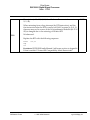
General remark: In order to prevent the use of instructions or sequences of instructions that
do not operate correctly, we encourage you to use the “lint563” program to identify such
cases and use alternative sequences of instructions. This program is available as part of the
Motorola DSP Tools CLAS package.
Silicon Errata
Errata
No.
Applies
to Mask
Errata Description
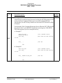
Description (added 5/1/1996):
ES1
1F92R
A Conditional Change-of-Flow instruction (Jcc/Bcc) to LA does not work
properly if interrupts are enabled.
Workaround: Not available
Description (added 5/1/1996):
ES2
1F92R
The DSP56301 cannot work with a low frequency crystal (less than 500
KHz) connected as its clock source between EXTAL and XTAL pins.
Workaround: Not available
Description (added 5/1/1996):
ES3
ES4
1F92R
If any DMA channel is active and a second DMA channel is enabled by
writing
DE = 1 and TM = 011 to its control register, and the next instructions cause
“transfer stall” (see Appendix B-3.4.2 in the DSP56300 core specification)
or “conditional transfer interlock” (see paragraph B-3.5.1 in the DSP56300
core specification), then the second DMA channel does not start data
transfer.
Workaround: Insert one NOP instruction between the DMA control
register write and the sequence causing the “transfer stall” or “conditional
transfer interlock”. Do not place a write instruction to the DMA control
register with DE = 1 and
TM = 011 as a second word of a fast interrupt routine.
Description (added 5/1/1996): Two sequential 1-cycle writes to the same
peripheral do not work properly.
1F92R
Workaround: Not available
Motorola, Semiconductor Products Sector 301CE1F92R_4_5
6501 William Cannon Drive West, Austin, Texas 78735-8598
ng 12/19/02 pg. 1
1995-2002 Motorola
Chip Errata
DSP56301 Digital Signal Processor
Mask: 1F92R
Errata
No.
Applies
to Mask
Errata Description
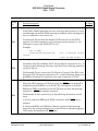
1. Description (added 5/1/1996):
ES5
1F92R
When external bus activity is disabled (OMR[4] is set) and there is a
contention between the DMA and core access to internal memory (access
to the same 256-word bank), the DMA properly.
Workaround:
2. Description (added 5/1/1996):
ES6
1F92R
When the stack extension is enabled and a nested DO loop with
consecutive LAs ends causing SP to return to 0, a stack extension
operation which fills the HW stack is wrongly executed (but no stack error
occurs), causing EP to be decremented under its lowest permitted value.
If this section of the memory belongs to another program task, damage
will be caused because of a stack extension operation that will overwrite
these two memory locations (EP-1 and
EP-2).
Workaround: Any of the following alternatives can be used:
a.
Guarantee that EP-1 and EP-2 memory locations are not used by any
task.
b.
Separate the two consecutive LAs by one instruction.
c.
Push a dummy value onto the stack before the nested DO loop.
3. Description (added 5/1/1996):
ES7
1F92R
The STOP instructiondoes not work properly.
Workaround: Not available
4. Description (added 5/1/1996):
ES8
1F92R
The IRQA, IRQB, IRQC, IRQD, PINIT/NMI, HCLK and RESET pins do
not have the proper 5 volt protection.
Workaround: Not required. The pins function correctly as specified. There
is no significant reliability degradation expected. It is recommended that
the system apply only 3.3 volt levels to these pins if possible.
DSP56301 Errata
1995-2002 Motorola
ng 12/19/02pg. 2
Chip Errata
DSP56301 Digital Signal Processor
Mask: 1F92R
Errata
No.
Applies
to Mask
Errata Description
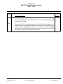
5. Description (added 5/1/1996):
ES9
1F92R
When the HI32 is in UB mode and pulse mode of HIRQ pin is set, and
TREQ and RREQ control bits in HCTR are changed simultaneously from
transmit request enable to receive request enable (or vice versa), the false
assertion of HIRQ pin might occur.
Note: This is not an issue if handshake mode of HIRQ pin is used.
Workaround: Do not change TREQ and RREQ control bits in HCTR
simultaneously from transmit request enable to receive request enable (or
vice versa). First disable both requests and then enable one (or both) of
them.
6. Description (added 5/1/1996):
1F92R
Stack extension mechanism does not work properly if a conditional jump
or branch to subroutine is used.
Workaround: For the proper operation, the following instructions should
not appear immediately after conditional jump or branch to subroutine:
ES10
XY Memory Data Move (A-6.76)
X Memory Move (A-6.71)
Y Memory Move (A-6.73)
Long Memory Data Move (A-6.75)
Immediate Short Data Move (A-6.68)
Register to Register Data Move (A-6.69)
Address Register Update (A-6.70)
X Memory and Register Data Move (A-6.72)
Y Memory and Register Data Move (A-6.74)
Arithmetic Instructions that allow Parallel Moves listed above
IFcc and IFcc.U (A-6.41)
Note: For this workaround, any of the listed above instructions should not
be the first instruction of interrupt service routine.
Description (added 5/1/1996):
ES11
1F92R
When the DMA channel is enabled in triggered-by-request mode and the
core is in the WAIT state, a false DMA data transfer might occur (e.g., one
DMA request might cause two data transfers instead of one).
Workaround: Not available
DSP56301 Errata
1995-2002 Motorola
ng 12/19/02pg. 3
Chip Errata
DSP56301 Digital Signal Processor
Mask: 1F92R
Errata
No.
Applies
to Mask
Errata Description
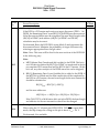
Description (added 5/1/1996):
ES12
1F92R
The CILP (Interrupt Line-Interrupt Pin Configuration Register) is defined
at address $FC instead of address $3C, as requested by the PCI
specification.
Workaround: Not available
Description (added 5/1/1996):
1F92R
When the DMA performs external memory accesses with priority higher
than the core and both continuous mode and interrupt enable bits are set
in the channel’s control register, then the DMA interrupt might not occur
if the core performs external memory access immediately after the
enabling (DE = 1) of the DMA channel.
ES14
Workaround: In this scenario any of the following alternatives can be
used:
a. Do not set continuous mode.
b. Use dynamic DMA-core priority.
c. Guarantee that the core will perform at least two instructions
fetched from
internal memory immediately after setting of the DE.
Description (added 5/1/1996):
1F92R
While stack extension is enabled and MOVE to/from SSH is followed by
Address Generation Interlock of Type0, then improper operation may
occur. For example, the following sequence may generate incorrect
results:
MOVE SSH,A
MOVE #0,R7
MOVE A,X:(R7)
ES15
Workaround: After MOVE to/from SSH use any instruction sequence
that does not cause Address Generation Interlock of Type0.
Note: No interrupt service routine should start with Address Generation
Interlock of Type0).
DSP56301 Errata
1995-2002 Motorola
ng 12/19/02pg. 4
Chip Errata
DSP56301 Digital Signal Processor
Mask: 1F92R
Errata
No.
Applies
to Mask
Errata Description
Description (added 5/1/1996):
ES16
1F92R
When the chip is powered up with PLL enabled (PINIT = 1), the skew
between EXTAL and CLKOUT after the PLL locks cannot be guaranteed
at high frequency (over 50 MHz, not 100% tested).
Workaround: If skew between EXTAL and CLKOUT is needed, power up
with PINIT = 0, and then enable the PLL by software.
Description (added 5/1/1996):
1F92R
A change-of-flow instruction that appears at LA-1 or LA-2 (or a two-word
change-of-flow instruction at LA-3) while stack extension is enabled may
cause improper operation if the preceding instruction activates the stack.
For example, the following sequences may generate incorrect results:
a. Example 1
DO #N,LABLE
...
MOVE SSH,N3
JSR R1
NOP
; stack activating instruction
; LA-1
; LA
LABLE
b. Example 2
ES17
DO #M,LABLE1
DO #N,LABLE2
...
NOP
; stack activating instruction
LABLE2
JSR R1
NOP
; LA-1
; LA
LABLE1
Workaround: For proper operation the following should be guaranteed:
a.
Stack activating instruction does not appear immediately before the
restricted above change of flow instruction.
Note: Any instruction at LA is a stack activating instruction, for example,
in the case of nested DO-loops.
b. Interrupt service routine should not include more than fifteen stack
pushes and pops.
DSP56301 Errata
1995-2002 Motorola
ng 12/19/02pg. 5
Chip Errata
DSP56301 Digital Signal Processor
Mask: 1F92R
Errata
No.
Applies
to Mask
Errata Description
Description (added 5/1/1996):
1F92R
If the HI32’s HCVR register is read in the PCI mode and DMA transfers
to DTXS are enabled, then false DMA transfers may occur.
ES18
Workaround: Since typically the HCVR is read for HC bit polling, use
HCVR write with HC = 0 instead of HC bit polling. The write can be
accepted by the HI32 only if HC is cleared by the HI32 hardware;
otherwise, the transaction will be retried. In the latter case, the “retry”
condition indirectly signals that HC is set, whereas a successfully finished
transaction means that HC is cleared by the HI32 hardware.
Description (added 5/1/1996):
1F92R
In the PCI mode, if the PCI master inserts more than one wait state when
the HI32’s HCVR register is read and there is data ready in HRXS, then
the HRXS will be read instead of HCVR.
Workaround: In this scenario use any of the following alternatives:
ES19
a.
Use HCVR write with HC = 0 instead of HC bit polling (see
workaround above).
b. Read the HCVR in a non one-word transaction starting from the
HI32 register with the lower PCI address (e.g., HSTR). The PCI master
must not extend the HCVR read data phase (usually, zero wait states can
be easily guaranteed for data phases after the first one).
DSP56301 Errata
1995-2002 Motorola
ng 12/19/02pg. 6
Chip Errata
DSP56301 Digital Signal Processor
Mask: 1F92R
Errata
No.
Applies
to Mask
Errata Description
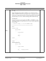
Description (added 5/1/1996):
1F92R
After HC bit is set by the host processor (writing the HCVR register) in UB
mode, the Host Command interrupt is executed as defined by the
specification, but HC bit may remain set even after HCP status bit in DSR
is cleared.
Workaround: Host Command Interrupt Service Routine (HC_ISR) should
be started with 1-cycle MOVEP instruction accessing any of the HI32’s
DSP-side registers (see two examples below).
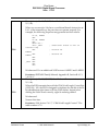
a. Example 1
ORG P:HC_ISR
MOVEP A,X:M_DSR
JSR <HCP_
ES20
; host command vector
; BSR could be used instead
of JSR
...
...
HCP_
...
...
RTI
; HCP ISR
b. Example 2
ORG P:HC_ISR
JSR >HCP_
; host command vector
; BSR could be used instead
of JSR
...
...
HCP_
DSP56301 Errata
MOVEP A,X:M_DSR
...
...
RTI
1995-2002 Motorola
; HCP ISR
ng 12/19/02pg. 7
Chip Errata
DSP56301 Digital Signal Processor
Mask: 1F92R
Errata
No.
Applies
to Mask
Errata Description
Description (added 5/1/1996):
1F92R
If the DMA channel performs non-zero wait state data accesses to/from
external memory and the DMA interrupt is enabled, a false interrupt may
occur in addition to the correct one.
ES21
Workaround: Ensure that the channel’s DTD status bit in the DSTR
register is set before jumping to the interrupt service routine (i.e., the
interrupt is correct only when DTD is set).
Example:
ORG P:I_DMA2
JSSET #M_DTD2,X:M_DSTR,ISR_
; ISR_ is interrupt service
routine
; label for DMA channel 2
Description (added 5/1/1996):
ES22
1F92R
Normally, if the PLL disabled, the PCAP pin may be connected to VCC, to
Ground, or be left floating. However, this device has a latchup sensitivity
on the PCAP pin.
Workaround: Do not connect the PCAP pin to Ground. If the PLL is not
being used, PCAP may be connected to VCC or be left floating. There is no
possibility of latchup if a capacitor is the only connection to PCAP.
Description (added 5/7/1996):
1F92R
When the HI32 operates in UB mode while the HIRQ pin is asserted in
handshake mode (HIRH is set in the DCTR), writing zero to both the
RREQ and TREQ control bits in the HCTR does not clear the interrupt
request (i.e., HIRQ pin remains asserted).
ES23
Workaround: In this scenario any of the following alternatives can be
used:
a. Do not clear both RREQ and TREQ control bits while HIRQ pin is
asserted.
b. After both RREQ and TREQ are cleared, service the last interrupt
request by the corresponding access to the HI32 host-side data registers.
This causes the deassertion of HIRQ pin.
DSP56301 Errata
1995-2002 Motorola
ng 12/19/02pg. 8
Chip Errata
DSP56301 Digital Signal Processor
Mask: 1F92R
Errata
No.
Applies
to Mask
Errata Description
Description (added 6/26/1996):
1F92R
Trace mode (TME bit is set in OSCR) does not work properly during REP
instruction execution.
ES24
Workaround: Host debugging software should disable tracing during
REP instruction execution and enable it only after the whole REP cycle is
complete. If the debugging software does not disable tracing during REP
instruction execution, the user must ensure that programs do not enter the
trace mode while executing a REP instruction.
DSP56301 Errata
1995-2002 Motorola
ng 12/19/02pg. 9
Chip Errata
DSP56301 Digital Signal Processor
Mask: 1F92R
Errata
No.
Applies
to Mask
Errata Description
Description (added 6/26/1996):
1F92R
If the HI32 is a PCI master and receives a target disconnect (TDIS = 1 in
DPSR), the Remaining Data Count (RDC[5:0] in DPSR) may be erroneous.
If the disconnected burst must be completed, the new Burst Length value
(BL[5:0] in DPMC) and address (AR[31:0] in DPMC and DPAR)
calculation may be incorrect.
Workaround: Reset the HI32 FIFOs (enter Mode 0) and regenerate the
disconnected burst. Minimize the probability of target disconnects by
selecting an appropriate Burst Length value.
Note: Note: This issue will be fixed in the next revision of the DSP56301
in the following way:
Note:
ES25
a. MDT (Master Data Transferred) bit is added to the DPSR. This bit is
set if all data (as defined by BL[5:0] in DPMC) is transferred in the latest completed PCI transaction and the HI32 is the PCI master. (If this
bit is set, any other analysis of the DPSR status bits can be skipped).
b. RDCQ (Remaining Data Count Qualifier) bit is added to the DPSR. If
the MDT bit is cleared and the data transfer should be completed by
the HI32 as a PCI master, the new burst length for the next transaction
should be calculated as
BL[5:0]new = RDC[5:0] + RDCQ,
and the new address as
AR[31:0]new = AR[31:0]old + BL[5:0]old - BL[5:0]new.
If the TAB, TRTY, or MAB status bit is set in the DPSR, the burst length
and address for the next transaction should not be changed.
Description (added 9/10/1996):
ES26
1F92R
When using the 5-V tolerant pins HP28, HP50, TXD, DE in open drain
mode, the chip clamps the voltage at the pin to about VCC + 0.4 V.
Workaround: Not available.
DSP56301 Errata
1995-2002 Motorola
ng 12/19/02pg. 10
Chip Errata
DSP56301 Digital Signal Processor
Mask: 1F92R
Errata
No.
Applies
to Mask
Errata Description
Description (added 9/10/1996):
ES27
1F92R
If the chip is in the Debug mode and the RESET pin is asserted to bring
the chip into Normal mode without asserting TRST at the same time, the
chip status continues to be read as “Debug” mode instead of the expected
“User” mode, when the status is read afterwards through the JTAG port.
Workaround: Assert the TRST pin while asserting the RESET pin.
Description (added 9/10/1996):
1F92R
If the chip is in the Debug mode and the TRST pin is asserted, the chip
status shows the chip status as “User” mode instead of the expected
“Debug” mode, when the status is read afterwards through the JTAG
port,.
ES28
Workaround: Execute the following JTAG commands before reading the
JTAG status:
a) Enable OnCE
b) DEBUG request
Afterwards, the status bits reflect the actual status of the chip and the DE
pin acknowledges “re-entering” the Debug mode.
Description (added 11/18/1996):
1F92R
After the BB pin output is driven high and released, the pin output
voltage level may not reach VCC. The issue depends on the application
board layout and the parameters of the chip process.
ES30
Workaround: Use a restricted board layout that includes a 1 kΩ pull-up
resistor connected to the BB pin with a 100 Ω resistor connected in series
with, and as close as possible to, the pin. The board route from the BB pin
to any component should guarantee the following parameters:
a. Route inductance < 40 nH
b. Route capacitance < 15 pF
c. Input capacitance < 8 pF
Such restrictions guarantee that when BB is driven high (deasserted), the
output voltage level will be above 2.25 V at VCC = 3.3 V.
DSP56301 Errata
1995-2002 Motorola
ng 12/19/02pg. 11
Chip Errata
DSP56301 Digital Signal Processor
Mask: 1F92R
Errata
No.
Applies
to Mask
Errata Description
Description (added 2/12/1997):
ES32
1F92R
Under the PCI specification, a PCI arbiter can park the PCI bus on a
specific device by asserting the GNT signal for that device, allowing the
device to have virtually instantaneous bus access (i.e, if GNT is asserted
for the device, no REQ assertion is required to start a transaction). The
device on which the bus is parked can either be a single preferred device
or the last device to use the bus (the recommended choice). The PCI
specification requires that when the bus is parked on a device and another
device requires the bus and the arbiter deasserts the GNT signal to
remove bus parking, the device on which the bus is parked must
immediately release the bus and not perform any transactions. However,
in the DSP56301, if the PCI arbiter performs bus parking on the HI32, and
the HI32 is configured as the PCI bus master, and the HI32 asserts the
HREQ signal at the same time that the PCI arbiter deasserts the HGNT
signal (removing the bus parking), the HI32 may hold the bus mastership
for one transaction.
Workaround:
Do not allow the PCI bus arbiter to park the bus on the HI32.
Description (added 3/3/1997):
ES33
1F92R
When using the JTAG instructions SAMPLE/PRELOAD, EXTEST, and
CLAMP, erroneous data may be driven out on the parallel pins and TDO.
Data cannot be shifted through the Boundary Scan Register (BSR) using
the SAMPLE/PRELOAD instruction. Because the BSR must be preloaded
using the SAMPLE/PRELOAD instruction, the EXTEST and CLAMP
instructions cannot be used for testing the board connections.
Workaround: None available.
Description (added 3/3/1997):
ES34
1F92R
The Self-Configuration procedure of the HI32 does not work properly
when executed from external memory (either program or data fetches).
Workaround: Download program and data to the internal memory and
then execute the Self-Configuration procedure from internal memory
(both program and data fetches).
DSP56301 Errata
1995-2002 Motorola
ng 12/19/02pg. 12
Chip Errata
DSP56301 Digital Signal Processor
Mask: 1F92R
Errata
No.
Applies
to Mask
Errata Description
Description (added 4/7/1997)
1F92R
When the HI32 is a PCI master and initiates any type of write transaction
after another PCI master performs Memory Write transaction to another
PCI agent, the DRXR FIFO pointers of the HI32 may be corrupted.
ES35
Workaround:
To guarantee that ‘valid’ DRXR data is not lost, it should be read prior the
HI32 initiates any type of the write transaction. This should be done after
each write transaction of any type initiated by the HI32 under mentioned
above conditions. Empty the DRXR FIFO reading both master and slave
‘dummy’ data according to the SRRQ and MRRQ status bits, using the
Core moves.
Description (added 9/2/1997):
ES37
1F92R
In PCI mode, improper HI32 operation may result if the HTXR/HRXS
registers are accessed by the PCI master at byte address Base_Address +
(N × 2048 + 16), where N is an integer from 1–31.
Workaround:
Not available.
Description (added 9/15/97):
1F92R
The HCLK pin of the HI32 presents an input capacitive load of almost 30
pF, which exceeds the permissible maximum load of 12 pF as specified in
the PCI Specification Version 2.1. This may cause improper HI32
operation in PCI systems.
ES41
Note: The effect of this extra load may vary from system to system, depending on PCI clock driver strength.
Workaround:
Use a zero-propagation-delay external PLL device (e.g., CY2305) to buffer
the PCI clock signal. This solution does not enable spread-spectrum PCI
clocking.
DSP56301 Errata
1995-2002 Motorola
ng 12/19/02pg. 13
Chip Errata
DSP56301 Digital Signal Processor
Mask: 1F92R
Errata
No.
Applies
to Mask
Errata Description
Description (added 3/3/98):
ES42
1F92R
When a Direct Memory Access (DMA) channel is in Line mode (i.e., the
DMA Transfer Mode is DTM = 010) with address modes defined by DMA
Three Dimensional mode D3D = 0 and DMA = 10010x (i.e., the DMA
Counter (DCO) is in mode A), and the DCO value is greater than $FFF,
then the DMA does not function properly. This address mode implies “no
update” at the destination and “no update” or “post increment by 1”
mode at the source.
Workaround:
Use Block Transfer mode (i.e., DTM = 000). For the DCO and DMA
Address Mode (DAM) settings described in this erratum, the Line
Transfer mode of DMA is identical to its Block Transfer mode, so this
combination is redundant. In fact, a block containing only one line is still
a block.
DSP56301 Errata
1995-2002 Motorola
ng 12/19/02pg. 14
Chip Errata
DSP56301 Digital Signal Processor
Mask: 1F92R
Errata
No.
Applies
to Mask
Errata Description
Description (added 3/3/98, modified 3/11/98):
Let’s say that “channel A” is the DMA channel servicing the HI32, and
that “channel B” is another DMA channel that has been disabled by
software. Then, depending on the DMA Request Source field (DRS[4:0])
of the two channels, channel A may be stalled by channel B being
disabled. Channel A may be stalled when the DMA Channel Enable (DE)
bit in the DMA Control Register is cleared by software in the following
cases:
1F92R
• DE bit of channel B cleared by software because of
- a Transfer Done from DMA channel 0 (DRSb = 00100) or
- an ESSI1 Receive Data (DRSb = 01100) or
then channel A may be stalled by a Host Slave Receive Data
(DRSa = 11100).
• DE bit of channel B cleared by software because of
ES44
- a Transfer Done from DMA channel 1 (DRSb = 00101) or
- an ESSI1 Transmit Data (DRSb = 01101) or
then channel A may be stalled by a Host Master Receive Data
(DRSa = 11101).
• DE bit of channel B cleared by software because of
- a Transfer Done from DMA channel 2 (DRSb = 00110) or
- an SCI Receive Data (DRSb = 01110) or
then channel A may be stalled by a Host Slave Transmit Data
(DRSa = 11110).
• DE bit of channel B cleared by software because of
- a Transfer Done from DMA channel 3 (DRSb = 00111) or
- an SCI Transmit Data (DRSb = 01111) or
then channel A may be stalled by a Host Master Transmit Data
(DRSa = 11111).
Workaround: Use either one of the following alternatives:
• Clear and set the DE bit of channel A immediately after you clear the
DE bit of channel B.
• Avoid a software clear of the DE bit of channel B.
DSP56301 Errata
1995-2002 Motorola
ng 12/19/02pg. 15
Chip Errata
DSP56301 Digital Signal Processor
Mask: 1F92R
Errata
No.
Applies
to Mask
Errata Description
Description (added 3/3/ 98):
1F92R
When the Host Command Vector Register (HCVR) is written in
Peripheral Component Interconnect (PCI) mode while the Receive Buffer
Lock Enable (RBLE) bit is set in the DSP PCI Control Register (DPCR), the
Host Data Transfer Complete (HDTC) status bit in DSP PCI Status
Register (DPSR) may be set falsely, thus also causing an HDTC interrupt
if that interrupt has been enabled by the Transfer Complete Interrupt
Enable (TCIE) bit in the DPCR.
Workaround:
ES45
Use either one of the following alternatives:
• Clear HDTC, if it is set, by writing it with 1 in the Host Command Interface Status Register (ISR).
• Clear HDTC, if it is set, by writing it with 1; use software-dependent
information to distinguish between a false and true HDTC setting. For
example, you do either of the following:
- Alter the destination address pointer if the DSP Receive Data Register (DRXR) data is being transferred by the DSP core. The pointer
will be changed if the HDTC setting is true.
- Alter the destination address or counter registers of the DMA channel if the DRXR data is being transferred by the DMA. The registers
will be changed if the HDTC setting is true.
Description (added 5/1/1996):
1F92R
JTAG-related errors:
ES56
The reset value of the JTAG Instruction Register is 1
(SAMPLE/PRELOAD), instead of 2 (ID-CODE), which is required by the
standard.
Workaround: Not available
DSP56301 Errata
1995-2002 Motorola
ng 12/19/02pg. 16
Chip Errata
DSP56301 Digital Signal Processor
Mask: 1F92R
Errata
No.
Applies
to Mask
Errata Description
Description (added 5/1/1996):
1F92R
JTAG-related errors:
ES57
The user may not read several ID devices in a daisy-chain as the DSP56301
inserts zeros after its IDR value.
Workaround: Read the device IDRs one at a time while keeping all the
other devices in BYPASS.
Description (added 5/1/1996):
1F92R
JTAG-related errors:
ES58
The user may not read the chip’s pre-FIFO, FIFO, or OGDBR registers
when in a daisy-chain configuration.
Workaround: Read these registers while keeping all the other devices in
BYPASS.
Description (added 5/1/1996):
1F92R
JTAG-related errors:
ES59
The user may not write the OnCE™ Command Register (OCR) when in a
daisy-chain configuration.
Workaround: Write OCR register while keeping all the other devices in
BYPASS.
Description (added 5/1/1996):
1F92R
JTAG-related errors:
ES60
The data in the Port A data bus D[23:0] and the HI32 pins HP[50:0] might
be erroneous in EXTEST JTAG mode.
The data in the BL pin might be erroneous in EXTEST JTAG mode.
Workaround: Do not use EXTEST for these pins.
DSP56301 Errata
1995-2002 Motorola
ng 12/19/02pg. 17
Chip Errata
DSP56301 Digital Signal Processor
Mask: 1F92R
Errata
No.
Applies
to Mask
Errata Description
Description (added 5/1/1996):
1F92R
JTAG-related errors:
ES61
After exiting EXTEST, a false debug request might be received.
Workaround: After exiting EXTEST, assert TRST pin (Test Reset) before
normal activity.
Description (added 5/3/98):
1F92R
The HI32 may generate a wrong PAR signal.
ES81
Workaround:
If possible, the system should ignore parity errors generated in such a
case.
7. Description (added 5/13/98):
1F92R
The BL pin may operate improperly when two consecutive manipulation
instructions (bset/bclr/bchg) use external memory as the destination.
Example of the sequence:
bset #5,x:(r0) ;; r0 is a pointer on an external memory address
ES82
bclr #7,x:(r3) ;; r3 is a pointer on an external memory address
Workaround :
Separate the consecutive bit manipulation instructions by any other
instruction, as in the following example:
bclr #7,x:(r3) ;; r3 is a pointer on an external memory address
nop
bset #5,x:(r0) ;; r0 is a pointer on an external memory address
DSP56301 Errata
1995-2002 Motorola
ng 12/19/02pg. 18
Chip Errata
DSP56301 Digital Signal Processor
Mask: 1F92R
Errata
No.
Applies
to Mask
Errata Description
Description (added 5/13/98):
1F92R
When software disables a DMA channel (by clearing the DE bit of the
DCR) , the DTD status bit of the channel may not be set if any of the
following events occur:
a. Software disables the DMA channel just before a conditional transfer
stall (Described by App B-3.5.1,UM).
b. Software disables the DMA channel at the end of the block transfer
(that is after the counter is loaded with its initial value and transfer of
the last word of the block is completed).
As a result, the Transfer Done interrupt might not be generated.
Workaround:
Avoid using the instruction sequence causing the conditional transfer
stall (See DSP56300 UM, App B-3.5.1 for description) in fast interrupt
service routines. Every time the DMA channel needs to be disabled by
software, the following sequence must be used :
ES84
bclr
#DIE,x:M_DCR
; not needed if DIE is cleared
bclr
#DE,x:M_DCR
; instead of two instructions above, one ’movep’ instruction may
be used
; to clear DIE and DE bits
movep
#DCR_Dummy_Value,x:M_DCR
bclr
#DE,x:M_DCR
nop
nop
Here, the DCR_Dummy_value is any value of the DCR register that complies
with the following requirements:
•
•
•
DE is set;
DIE is set if Transfer Done interrupt request should be generated
and cleared otherwise;
DRS[4:0] bits must encode a reserved DMA request source (see
the following list of reserved DRS values);
List of reserved DRS[4:0] values (per device):
•
DSP56302, DSP56309, DSP56303, DSP56304, DSP56362 —
10101-11111
•
•
•
DSP56301 Errata
DSP56305 — 11011
DSP56301 — 10011-11011
DSP56307 — 10111-11111
1995-2002 Motorola
ng 12/19/02pg. 19
Chip Errata
DSP56301 Digital Signal Processor
Mask: 1F92R
Errata
No.
Applies
to Mask
Errata Description
8. Description (added 4/23/98):
ES86
1F92R
If the HI32 performs a write transaction as a PCI master and the
transaction is disconnected by the target, the value of the MTRQ status bit
in the DPSR register may be wrong.
Workaround:
Do not use an MTRQ status bit-related interrupt or polling. (The related
DMA functionality is not affected by this issue.)
9. Description (added 5/28/98):
1F92R
When the HI32 is an active PCI target, it does not set the DPE bit in the
CSTR register if an address parity error occurs.
ES87
Workaround:
The Host can get information about the Address Parity status either by
reading the SSE bit (in the CSTR) or by indirectly reading the (e.g. via Host
Command) the APER bit in the DPSR register.
Description (added 6/25/98):
ES89
1F92R
If the SCI Receiver is programmed to work with a different serial clock
than the SCI Transmitter so that either the Receiver or Transmitter is using
the external serial clock and the other is using the internally-generated
serial clock—RCM and TCM in the SCCR are programmed differently)—
then the internal serial clock generator will not operate and the SCI
portion (Receiver or Transmitter) clocked by the internal clock will be
stuck.
Workaround:
Do not use SCI with the two SCI portions (Receiver and Transmitter)
clocked by different serial clocks; use either both externally or both
internally clocked.
Or:
When using both portions of the SCI (Receiver & Transmitter), do not
program different values on RCM and TCM in the SCCR.
DSP56301 Errata
1995-2002 Motorola
ng 12/19/02pg. 20
Chip Errata
DSP56301 Digital Signal Processor
Mask: 1F92R
Errata
No.
Applies
to Mask
Errata Description
Description (added 8/15/98):
ES95
1F92R
If more than a single DMA channel is enabled while the DSP stays in the
WAIT processing state, and triggering one of the DMA channels causes an
exit from the WAIT state (See A-6.115, UM), triggering another DMA
channel might cause improper DMA operation.
Workaround:
Assure that only a single DMA channel can be triggered during DSP
WAIT state. If the application cannot guarantee this, other DMA channels
should be disabled before the WAIT processing state is entered and then
reenabled after WAIT state is exited.
Description (added 10/26/98):
1F92R
If the reset mode is expanded mode (for example, mode 0 or mode 8 on
the DSP5630x), A MOVE (not a PROGRAM FETCH) from internal P
memory to any destination may not work properly.
Workaround:
ES101
After each reset (RESET) negation and before the first move from internal
program memory, execute the following sequence:
BSET
NOP
NOP
NOP
BCLR
DSP56301 Errata
#M_CE,sr
#M_CE,sr
1995-2002 Motorola
ng 12/19/02pg. 21
Chip Errata
DSP56301 Digital Signal Processor
Mask: 1F92R
Errata
No.
Applies
to Mask
Errata Description
Description: (added 11/24/98):
1F92R
An improper operation may occur when all the following conditions
apply:
•
•
ES104
•
The DMA channel is in a mode that does not automatically clear
the DE bit at the end of the block (DTM[2:0] = 1xx in DCR).
This channel is disabled by software (by clearing DE in DCR)
while it is triggered for a new transfer.
The previous operation is not yet completed.
Workaround:
The DMA channel should be disabled only when it is not triggered for a
new transfer, i.e. when the DACT bit in the DSTR register is cleared.
Note: To perform this operation most efficiently, all other DMA channels
should be disabled.
Description (added 12/8/98):
1F92R
The HDTC status bit (relevant only if the RBLE control bit is set) may not
be set properly when both of the following conditions apply:
a) DSP software clears the HDTC bit while the PCI bus is parked on the
HI32.
b) The PCI master read transaction is initiated by the HI32 while the bus
is still parked on the HI32.
ES107
Workaround:
Use one of the following alternatives:
1. Avoid bus parking on the HI32.
2. Enter the Personal Software Reset (HM[2:0]=0) in HDTC ISR.
3. Poll the MRRQ and SRRQ status bits before the start of each master read
transaction (e.g. in MARQ ISR). Start this transaction only when both
MRRQ and SRRQ are cleared. The HDTC status bit should be cleared by
the DSP software as defined in the specification.
DSP56301 Errata
1995-2002 Motorola
ng 12/19/02pg. 22
Chip Errata
DSP56301 Digital Signal Processor
Mask: 1F92R
Errata
No.
Applies
to Mask
Errata Description
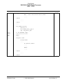
Description (added 4/19/99, revised 4/30/99):
ES114
1F92R
A DMA channel may operate improperly when the address mode of this
channel is defined as three-dimensional (D3D=1) and DAM[5:0] = 1xx 1
10 or DAM[5:0] = 01xx 10 (i.e., triple counter mode is E).
Workaround:
Use the triple counter modes C(DAM[1:0]=00) or D(DAM[1:0]=01)
instead of the E(DAM[1:0]=10) mode.
Description (added 4/19/99):
1F92R
When a DMA channel (called channel A) is disabled by software clearing
the channel’s DCR[DE] bit, the DTD bit may not get set, and the DMA end
of the block interrupt may not happen if one of the following occurs:
1. There is another channel (channel B) executing EXTERNAL accesses,
and the DE bit of channel A is being cleared by software at the end of the
channel B word transfer - if channel B is in Word transfer mode, or at the
end of the channel B line transfer - if channel B is in Line Transfer mode,
or at the end of the channel B block transfer - if channel B is in Block
transfer mode.
ES115
2. This channel (A) is executing EXTERNAL accesses, and the DE bit of
this channel (A) is being cleared by software at the end of the channel B
word transfer - if channel B is in Word transfer mode, or at the end of the
channel B line transfer - if channel B is in Line transfer mode.
Workaround:
Avoid executing a DMA external access when any DMA channel should
be disabled. This can be done as follows. Every time the DMA channel
needs to be disabled by software, the following sequence must be used:
;; initialize an unused DMA channel "C"
movep
#DSR_swflag, x:M_DSRC
;; here DSR_swflag is an
;; unused X, Y or P memory
;; location, should
;; be initialized to
;; $800000
;; M_DSRC - address of the
;; channel C DSR register.
DSP56301 Errata
1995-2002 Motorola
ng 12/19/02pg. 23
Chip Errata
DSP56301 Digital Signal Processor
Mask: 1F92R
Errata
No.
Applies
to Mask
Errata Description
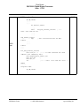
movep
#DDR_swflag, x:M_DDRC
movep
#TR_LENGTH, x:M_DCOC
register .movep
ES115
cont.
DSP56301 Errata
;;
;;
;;
;;
;;
;;
;;
DDR_swflag is an unused
X, Y or P memory
location, should be
initialized to $000000
M_DDRC address of the channel C
DDR register .
1F92R
;; see below the definition
;; of the TR_LENGTH value,
;; M_DCOC - address
;; of the channel C DCO
#1f0240, x:M_DCRC ;; M_DCRB - address of the
;; channel C DCR register.
;; Set transfer mode ;; block transfer,
;; triggered by
;; software highest
;; priority, continuous
;; mode on no-update
;; source and destination
;; address mode X memory
;; location for source
;; and destination (can be
;; chosen by
;; user accordingly to
;; DSR_swflag/DDR_swflag)
1995-2002 Motorola
ng 12/19/02pg. 24
Chip Errata
DSP56301 Digital Signal Processor
Mask: 1F92R
Errata
No.
Applies
to Mask
Errata Description
1F92R
;; disable DMA channel "A"
ES115
cont.
ori
bset
bclr
#3, mr
;; mask all interrupts
#23, x:M_DCRC
;; enable DMA channel C
#23,x:DDR_swflag,* ;; wait until DMA channel C
;; begin transfer
bclr
nop
nop
jclr
#23, x:M_DCRA
#M_DTDA, x:M_DSTR,*
;; disable DMA channel A
;; polling DTD bit of the DMA
;; channel A,
The TR_LENGTH value can be defined as the maximum length of the
external DMA transfer——from the length of the read DMA cycle and
from the length of the write DMA cycle. The length of the external
read/write DMA cycle can be defined as the length of the PORTA
external access. The length of the internal read/write DMA cycle
can be defined in the errata case as 2 DSP clock cycles. The
TR_LENGTH can be found as sum of the lengths of the DMA read and
DMA write cycles.
Description (added 9/11/99) (reclassified from documentation to silicon
errata 11/11/99):
1F92R
When an external PCI master executes a configuration space read from
the HI32 with an odd number of byte lanes enabled (for example, BE3 –
BE0 = 1000), the DSP drives the parity signal (HPAR) with the wrong
value. This is because the BE3 – BE0 signals are ignored (erroneously)
when generating the parity value during configuration space reads.
ES124
Workaround: None.
Pertains to: The HI32 (PCI) chapter of the user’s manual, in the section on
PCI Mode (DCTR[HM]=$1). In Revision 2 of the DSP56301 User’s
Manual, this section is 6.5.2 on page 6-14. The information should
accompany the bullet on Memory-Space and configuration transactions
as a target.
NOTE: Was documentation errata, ED39.
DSP56301 Errata
1995-2002 Motorola
ng 12/19/02pg. 25
Chip Errata
DSP56301 Digital Signal Processor
Mask: 1F92R
DOCUMENTATION ERRATA
Errata No.
Applies
to Mask
Document Update
10. Description (revised 11/9/98):
1F92R
XY memory data move does not work properly if the X-memory move
destination is internal I/O and the Y-memory move source is a register
used as destination in the previous adjacent move from non Ymemory OR the Y-memory move destination is a register used as
source in the next adjacent move to non Y-memory.
Here are examples of the two cases (where x:(r1) is a peripheral):
Example 1:
ED1
move #$12,y0
move x0,x:(r7) y0,y:(r3) (while x:(r7) is a peripheral).
Example 2:
mac
move
x1,y0,a x1,x:(r1)+
y0,y1
y:(r6)+,y0
This is not a bug, but a documentation update. Any of the following
alternatives can be used:
a.
Separate these two consecutive moves by any other instruction.
b. Split XY Data Move to two moves.
Description (added 5/1/1996):
ED2
1F92R
BL pin timings T198 and T199 in the Data Sheet are changed,
improving the arbitration latency:
T198 is 5 ns (max), T199 is 0 ns (min).
This is not a bug, but a documentation update.
Description (added 5/7/1996):
ED3
1F92R
A one-word conditional branch instruction at LA-1 is not allowed.
This is not a bug, but a documentation update.
DSP56301 Errata
1995-2002 Motorola
ng 12/19/02pg. 26
Chip Errata
DSP56301 Digital Signal Processor
Mask: 1F92R
Description (added 11/11/1996):
1F92R
The following instructions should not start at address LA:
ED4
MOVE to/from Program space {MOVEM, MOVEP (only the P space
options)}
This is not a bug but a documentation update (Appendix B, DSP56300
Family Manual).
ED6
ED7
Description (added 4/9/98)
1F92R
When the HIRQ pin is used in pulse mode (HIRH=0 in DCTR), the
LT[7:0] value (in CLAT) should not be zero. This is not a bug but a
documentation update.
Description (added 1/27/98):
1F92R
When activity passes from one DMA channel to another and the DMA
interface accesses external memory (which requires one or more wait
states), the DACT and DCH status bits in the DMA Status Register
(DSTR) may indicate improper activity status for DMA Channel 0
(DACT = 1 and DCH[2:0] = 000).
Workaround:
None.
Pertains to: DSP56300 Family Manual, Sections 8.1.6.3 and 8.1.6.4
1F92R
Description (added 1/27/98):
ED8
When activity passes from one DMA channel to another and the DMA
interface accesses external memory (which requires one or more wait states),
the DACT and DCH status bits in the DMA Status Register (DSTR) may
indicate improper activity status for DMA Channel 0 (DACT = 1 and
DCH[2:0] = 000).
Workaround:
None.
Pertains to: DSP56300 Family Manual, Sections 8.1.6.3 and 8.1.6.4
DSP56301 Errata
1995-2002 Motorola
ng 12/19/02pg. 27
Chip Errata
DSP56301 Digital Signal Processor
Mask: 1F92R
1F92R
Description (added 1/27/98):
When the SCI is configured in Synchronous mode, internal clock, and all the
SCI pins are enabled simultaneously, an extra pulse of 1 DSP clock length is
provided on the SCLK pin.
ED9
Workaround:
a. Enable an SCI pin other than SCLK.
b. In the next instruction, enable the remaining SCI pins, including the
SCLK pin.
Pertains to: UM, SCI Chapter (Use the 302 UM as your reference, Section
8.4.2, “SCI Initialization”)
Description (added 5/13/98):
ED10
1F92R
The HI32 may operate improperly in PCI mode when the TWSD bit is
set in the HCTR register.
Workaround:
Do not set the TWSD bit in the HCTR register; this bit is reserved. This
is a documentation change.
Description (added 5/13/98):
1F92R
When the HI32 is in PCI mode, the HTF control bits affect the address
insertion (the IAE bit is set in the DPCR register) in the same way they
affect the transferred data.
Address as appears on the PCI bus: $12345678
ED12
HTF[1:0]
Inserted Address
00
01
10
11
$005678,
$345678
$345678
$123456
$001234
Workaround:
This is a documentation update.
Description (added 5/15/98):
ED13
DSP56301 Errata
1F92R
When the HI32 is in PCI mode, the Insert Address Enable control bit
(IAE=1) can be set only with the Receive Buffer Lock Enable control bit
set (RBLE=1 in the DPCR register.)
1995-2002 Motorola
ng 12/19/02pg. 28
Chip Errata
DSP56301 Digital Signal Processor
Mask: 1F92R
Description (added 7/21/98):
ED15
1F92R
The DRAM Control Register (DCR) should not be changed while
refresh is enabled. If refresh is enabled only a write operation that
disables refresh is allowed.
Workaround:
First disable refresh by clearing the BREN bit, than change other bits
in the DCR register, and finally enable refresh by setting the BREN bit.
Description (added 9/28/98):
ED17
1F92R
In all DSP563xx technical datasheets, a note is to be added under "AC
Electrical Characteristics" that although the minimum value for
"Frequency of Extal" is 0MHz, the device AC test conditions are
15MHz and rated speed.
Workaround:
N/A
ED18
Description (added 11/2/98):
1F92R
The PCI host must not change the values of the HBE[3:0] bits during
PCI read transactions from the HI32 as a PCI target.
Description (added 11/9/98):
1F92R
To guarantee the proper HI32 operation, the DMA should service the
HI32 under the following restrictions:
ED19
•
Two DMA channels should not service the DRXR FIFO if master and slave data is mixed there.
• The DMA data transfers should not be concurrent with the
56300 Core data transfers to/from the same HI32 data FIFO.
Description (added 11/24/98):
1F92R
In the Technical Datasheet Voh-TTL should be listed at 2.4 Volts, not
as:
ED20
TTL = Vcc-0.4
Workaround:
This is a documentation update.
DSP56301 Errata
1995-2002 Motorola
ng 12/19/02pg. 29
Chip Errata
DSP56301 Digital Signal Processor
Mask: 1F92R
Description (added 11/24/98):
ED21
1F92R
In the Technical Datasheet Iol should be listed as 1.6 mA, not as 3.0
mA.
Workaround:
This is a documentation update.
Description (added 11/24/98):
ED24
1F92R
The technical datasheet supplies a maximum value for internal supply
current in Normal, Wait, and Stop modes. These values will be
removed because we will specify only a "Typical" current.
Workaround:
This is a documentation update.
DSP56301 Errata
1995-2002 Motorola
ng 12/19/02pg. 30
Chip Errata
DSP56301 Digital Signal Processor
Mask: 1F92R
Description (added 12/16/98):
1F92R
Current definition:
HDTC is set if SRRQ and MRRQ are cleared (i.e. the host-to-DSP data
path is emptied by DSP56300 core reads) under one of the following
conditions:
•
ED25
a non-exclusive PCI write transaction to the HTXR terminates
or completes
• HLOCK is negated after the completion of an exclusive write
access to the HTXR
• the HI32 initiates a read transaction. The HI32 disconnects
(retry or disconnect-C) forthcoming write accesses to the HTXR
as long as HDTC is set.
New definition:
HDTC is set if SRRQ and MRRQ are cleared (i.e. the host-to-DSP data
path is emptied by DSP56300 Core reads) under one of the following
conditions:
•
a non-exclusive PCI write transaction to the HTXR terminates
or completes
• HLOCK is negated after the completion of an exclusive write
access to the HTXR. The HI32 disconnects (retry or disconnectC) forthcoming write accesses to the HTXR as long as HDTC is
set.
Note: The HDTC bit is not set after a read transaction initiated by the
HI32 as a PCI master.
Workaround:
NTR
Description (added 1/6/99):
1F92R
The specification DMA Chapter is wrong.
ED26
“Due to the DSP56300 Core pipeline, after DE bit in DCRx is set, the
corresponding DTDx bit in DSTR will be cleared only after two
instruction cycles.”
Should be replaced with:
“Due to the DSP56300 Core pipeline, after DE bit in DCRx is set, the
corresponding DTDx bit in DSTR will be cleared only after three
instruction cycles.”
DSP56301 Errata
1995-2002 Motorola
ng 12/19/02pg. 31
Chip Errata
DSP56301 Digital Signal Processor
Mask: 1F92R
Description (added 1/7/1997; identified as Documentation Errata
2/1/99):
1F92R
When two consecutive LAs have a conditional branch instruction at
LA-1 of the internal loop, the part does not operate properly. For
example, the following sequence may generate incorrect results:
ED28
DO #5, LABEL1
NOP
DO #4, LABEL2
NOP
MOVE (R0) +
BSCC _DEST
internal loop
NOP
LABEL2
NOP
LABEL1
NOP
NOP
_DEST NOP
NOP
RTS
; conditional branch at LA-1 of
; internal LA
; external LA
Workaround: Put an additional NOP between LABEL2 and LABEL1.
Pertains to: DSP56300 Family Manual, Appendix B, Section B-4.1.3,
“At LA-1.”
Description (added 9/12/1997; identified as a Documentation errata
2/1/99):
ED29
1F92R
When the ESSI transmits data with the CRA Word Length Control bits
(WL[2:0]) = 100, the ESSI is designed to duplicate the last bit of the 24bit transmission eight times to fill the 32-bit shifter. Instead, after
shifting the 24-bit word correctly, eight 0s are being shifted.
Workaround:
None at this time.
Pertains to: UM, Section 7.4.1.7, “CRA Word Length Control.” The
table number is 7-2.
DSP56301 Errata
1995-2002 Motorola
ng 12/19/02pg. 32
Chip Errata
DSP56301 Digital Signal Processor
Mask: 1F92R
Description (added 9/12/1997; identified as a Documentation errata
2/1/99):
1F92R
When the ESSI transmits data in the On-Demand mode (i.e., MOD = 1
in CRB and DC[4:0] = $00000 in CRA) with WL[2:0] = 100, the
transmission does not work properly.
ED30
Workaround:
To ensure correct operation, do not use the On-Demand mode with
the
WL[2:0] = 100 32-bit Word-Length mode.
Pertains to: UM, Section 7.5.4.1, “Normal/On-Demand Mode
Selection.”
Description (added 9/12/1997; modified 9/15/1997; identified as a
Documentation errata 2/1/99):
1F92R
Programming the ESSI to use an internal frame sync (i.e., SCD2 = 1 in
CRB) causes the SC2 and SC1 signals to be programmed as outputs. If
however, the corresponding multiplexed pins are programmed by the
Port Control Register (PCR) to be GPIOs, then the GPIO Port Direction
Register (PRR) chooses their direction, but this causes the ESSI to use
an external frame sync if GPIO is selected.
ED31
Note: This errata and workaround apply to both ESSI0 and ESSI1.
Workaround:
To assure correct operation, either program the GPIO pins as outputs
or configure the pins in the PCR as ESSI signals.
Note: The default selection for these signals after reset is GPIO.
Pertains to: UM, Section 7.4.2.4, “CRB Serial Control Direction 2
(SCD2) Bit 4”
DSP56301 Errata
1995-2002 Motorola
ng 12/19/02pg. 33
Chip Errata
DSP56301 Digital Signal Processor
Mask: 1F92R
Description (added 11/9/98; identified as a Documentation errata
2/1/99):
1F92R
When returning from a long interrupt (by RTI instruction), and the
first instruction after the RTI is a move to a DALU register (A, B, X, Y),
the move may not be correct, if the 16-bit arithmetic mode bit (bit 17 of
SR) is changed due to the restoring of SR after RTI.
ED32
Workaround:
Replace the RTI with the following sequence:
movec
nop
rti
ssl,sr
Pertains to: DSP56300 Family Manual. Add a new section to Appendix
B that is entitled “Sixteen-Bit Compatibility Mode Restrictions.”
DSP56301 Errata
1995-2002 Motorola
ng 12/19/02pg. 34
Chip Errata
DSP56301 Digital Signal Processor
Mask: 1F92R
Description (added 12/16/98; identified as a Documentation errata
2/1/99):
1F92R
When Stack Extension mode is enabled, a use of the instructions
BRKcc or ENDDO inside do loops might cause an improper operation.
If the loop is non nested and has no nested loop inside it, the erratais
relevant only if LA or LC values are being used outside the loop.
Workaround:
If Stack Extension is used, emulate the BRKcc or ENDDO as in the
following examples. We split between two cases, finite loops and do
forever loops.
1) Finite DO loops (i.e. not DO FOREVER loops)
==============================================
BRKcc
Original code:
do #N,label1
.....
.....
do #M,label2
.....
.....
BRKcc
.....
.....
ED33
label2
.....
.....
label1
Will be replaced by:
do #N, label1
.....
.....
do #M, label2
.....
.....
Jcc
fix_brk_routine
.....
.....
DSP56301 Errata
1995-2002 Motorola
ng 12/19/02pg. 35
Chip Errata
DSP56301 Digital Signal Processor
Mask: 1F92R
nop_before_label2
nop
label2
.....
.....
label1
....
....
1F92R
; This instruction must be NOP.
fix_brk_routine
move #1,lc
jmp nop_before_label2
ENDDO
-----Original code:
do #M,label1
.....
.....
do #N,label2
.....
.....
ENDDO
.....
.....
ED33
cont.
label2
.....
.....
label1
Will be replaced by:
do #M, label1
.....
.....
do #N, label2
.....
.....
JMP
fix_enddo_routine
DSP56301 Errata
1995-2002 Motorola
ng 12/19/02pg. 36
Chip Errata
DSP56301 Digital Signal Processor
Mask: 1F92R
1F92R
nop_after_jmp
NOP ; This instruction must be NOP.
.....
.....
label2
.....
.....
label1
....
....
fix_enddo_routine
move #1,lc
move #nop_after_jmp,la
jmp nop_after_jmp
ED33
cont.
2) DO FOREVER loops
===================
BRKcc
----Original code:
do #M,label1
.....
.....
do forever,label2
.....
.....
BRKcc
.....
.....
label2
.....
.....
label1
DSP56301 Errata
1995-2002 Motorola
ng 12/19/02pg. 37
Chip Errata
DSP56301 Digital Signal Processor
Mask: 1F92R
Will be replaced by:
1F92R
do #M,label1
.....
.....
do forever,label2
.....
.....
JScc
fix_brk_forever_routine
note: JScc and not Jcc
.....
.....
ED33
cont.
nop_before_label2
nop
label2
.....
.....
label1
....
....
; <---
; This instruction must be NOP.
fix_brk_forever_routine
move ssh,x:<..> ; <..> is some reserved not used
address (for temporary data)
move #nop_before_label2,ssh
bclr #16,ssl
;
move #1,lc
rti
; <---- note: "rti" and not "rts" !
ENDDO
-----Original code:
do #M,label1
.....
.....
DSP56301 Errata
1995-2002 Motorola
ng 12/19/02pg. 38
Chip Errata
DSP56301 Digital Signal Processor
Mask: 1F92R
1F92R
do forever,label2
.....
.....
ENDDO
.....
.....
label2
.....
.....
label1
Will be replaced by:
ED33
cont.
do #M,label1
.....
.....
do forever,label2
.....
.....
JSR
fix_enddo_routine
; <--- note:
JSR and not JMP
nop_after_jmp
NOP ; This instruction should be NOP
.....
.....
label2
.....
.....
label1
....
....
fix_enddo_routine
nop
move #1,lc
bclr #16,ssl
move #nop_after_jmp,la
rti
; <--- note: "rti" and not "rts"
Pertains to: DSP56300 Family Manual, Section B-4.2, “General Do
Restrictions.”
DSP56301 Errata
1995-2002 Motorola
ng 12/19/02pg. 39
Chip Errata
DSP56301 Digital Signal Processor
Mask: 1F92R
Description (added 1/5/99; identified as a Documentation errata
2/1/99):
1F92R
When stack extansion is enabled, the read result from stack may be
improper if two previous executed instructions cause sequential read
and write operations with SSH. Two cases are possible:
Case 1:
For the first executed instruction: move from SSH or bit manipulation
on SSH (i.e. jclr, brclr, jset, brset, btst, bsset, jsset, bsclr, jsclr).
For the second executed instruction: move to SSH or bit manipulation
on SSH (i.e. jsr, bsr, jscc, bscc).
For the third executed instruction: an SSL or SSH read from the stack
result may be improper - move from SSH or SSL or bit manipulation
on SSH or SSL (i.e., bset, bclr, bchg, jclr, brclr, jset, brset, btst, bsset,
jsset, bsclr, jsclr).
ED34
Workaround:
Add two NOP instructions before the third executed instruction.
Case 2:
For the first executed instruction: bit manipulation on SSH (i.e. bset,
bclr, bchg).
For the second executed instruction: an SSL or SSH read from the stack
result may be improper - move from SSH or SSL or bit manipulation
on SSH or SSL (i.e., bset, bclr, bchg, jclr, brclr, jset, brset, btst, bsset,
jsset, bsclr, jsclr).
Workaround:
Add two NOP instructions before the second executed instruction.
Pertains to: DSP56300 Family Manual, Appendix B, add a new section
called “Stack Extension Enable Restrictions.” Cover all cases. Also, in
Section 6.3.11.15, add a cross reference to this new section.
DSP56301 Errata
1995-2002 Motorola
ng 12/19/02pg. 40
Chip Errata
DSP56301 Digital Signal Processor
Mask: 1F92R
Description (added 4/19/99):
1F92R
In paragraph 6.1.1.11 on page 6-12 of the 301 User’s Manual, there is
an error, as follows:
ED37
"HIRQ_ is asserted by the HI32 when a host interrupt request (recieve
and/or transmit) is generated in the HI32"
Workaround/correction:
Should be:
"HIRQ_ is asserted by the HI32 when a host interrupt request (receive
and/or transmit) is generated in the HI32 (as described in paragraphs
6.2.1.1, 6.2.1.1 and 6.2.1.4)."
Description (added 7/14/99):
ED38
1F92R
If Port A is used for external accesses, the BAT bits in the AAR3-0
registers must be initialized to the SRAM access type (i.e. BAT = 01) or
to the DRAM access type (i.e. BAT = 10). To ensure proper operation
of Port A, this initialization must occur even for an AAR register that
is not used during any Port A access. Note that at reset, the BAT bits
are initialized to 00.
Pertains to: DSP56300 Family Manual, Port A Chapter (Chapter 9 in
Revision 2), description of the BAT[1 –0] bits in the AAR3 - AAR0
registers. Also pertains to the core chapter in device-specific user’s
manuals that include a description of the AAR3 - AAR0 registers with
bit definitions (usually Chapter 4).
DSP56301 Errata
1995-2002 Motorola
ng 12/19/02pg. 41
Chip Errata
DSP56301 Digital Signal Processor
Mask: 1F92R
Description (added 11/11/99):
When an instruction with all the following conditions follows a repeat
instruction, then the last move will be corrupted.:
1. The repeated instruction is from external memory.
2. The repeated instruction is a DALU instruction that includes 2 DAL
registers, one as a source, and one as destination (e.g. tfr, add).
3. The repeated instruction has a double move in parallel to the DALU
instruction: one move’s source is the destination of the DALU
instruction (causing a DALU interlock); the other move’s destination
is the source of the DALU instruction.
Example:
1F92R
rep #number
tfr x0,a x(r0)+,x0 a,y0 ; This instruction is from external memory
|__|_________|------|----------> This is condition 3 second part.
|_____________|----------> This is condition 3, first part - DALU interlock
ED40
In this example, the second iteration before the last, the "x(r0)+,x0"
doesn’t happen. On the first iteration before the last, the X0 register is
fixed with the "x(r0)+,x0", but the "tfr x0,a" gets the wrong value from
the previous iteration’s X0. Thus, at the last iteration the A register is
fixed with "tfr x0,a", but the "a,y0" transfers the wrong value from the
previous iteration’s A register to Y0.
Workaround:
1. Use the DO instruction instead; mask any necessary interrupts
before the DO.
2. Run the REP instructions from internal memory.
3. Don’t make DALU interlocks in the repeated instruction. After the
repeat make the move. In the example above, all the "move a,y0" are
redundant so it can be done in the next instruction:
rep #number
tfr x0,a
x(r0)+,x0
move a,y0
If no interrupts before the move is a must, mask the interrupts before
the REP.
Pertains to: DSP56300 Family Manual, Rev. 2, Section A.3,
“Instruction Sequence Restrictions.”
DSP56301 Errata
1995-2002 Motorola
ng 12/19/02pg. 42
Chip Errata
DSP56301 Digital Signal Processor
Mask: 1F92R
1F92R
Description (added on 3/22/2000)
ED42
The DMA End-of-Block-Transfer interrupt cannot be used if DMA is
operating in the mode in which DE is not cleared at the end of the block
transfer (DTM = 100 or 101).
Pertains to:
DSP56300 Family Manual, Rev. 2, Section 10.4.1.2, “End-of-Block-Transfer
Interrupt.” Also, Section 10.5.3.5, “DMA Control Registers (DCR[5–0],”
discussion of bits 21 – 19 (DTM bits).
Description (added 12/10/2001):
1F92R
The following sequence gives erroneous results:
1) A different slave on the bus terminates a transaction (for example,
assertion of "stop" ).
2) Immediately afterwards (no more than one PCI clock), the chip’s
memory space control/status register at PCI address ADDR is read in
a single-word transaction. In this transaction, the chip drives to the
bus the data corresponding to the register at PCI address ADDR+4,
instead of the requested ADDR.
NOTE: ADDR is the PCI address of one of the following registers:
HCTR (ADDR=$10) , HSTR (ADDR=$14), or HCVR (ADDR=$18),
and not the data register.
ED46
Workaround:
The user should find a way to set/clear at least one bit in the control/status
registers to clearly differentiate between them. For example, you can set
HNMI in the HCVR, as this bit will always be 0 in the HSTR. If NMI cannot
be used, then HCVR{HV4,HV3,HV2} and HSTR{HF5,HF4,HF3} can be set
in any combinations that distinguish between HCVR and HSTR data reads.
Pertains to:
DSP56301 User’s Manual: Put this errata text as a note in the description of
the HCTR (p.
6-48), the HSTR (p. 6-57), and the HCVR (p. 6-59). These page numbers are
for Revision 3 of the manual.
DSP56305 User’s Manual: Put this errata text as a note in the description of
the HCTR (p. 6-54), the HSTR (p. 6-68), and the HCVR (p. 6-72). These page
numbers are for Revision 1of the manual.
DSP56301 Errata
1995-2002 Motorola
ng 12/19/02pg. 43
Chip Errata
DSP56301 Digital Signal Processor
Mask: 1F92R
Description (added 9/10/1996 as ES29; reclassified as a
documentation erratum on 8/2/2002):
1F92R
When the SCI transmitter is used in Synchronous mode, the last bit of
the transmitted byte might be truncated to the half of the serial cycle.
ED50
Workaround: Not available.
Motorola and
are registered trademarks of Motorola, Inc.
OnCE is a trademark of Motorola, Inc.
NOTES
1. An over-bar (i.e., xxxx) indicates an active-low signal.
2. The letters in the right column tell which DSP56301 mask numbers apply.
3. The Motorola DSP website has additional documentation updates that can be accessed at the
following URL:
http://www.motorola-dsp.com/
4. Information contained in the addendum to the DSP56301 data sheet applies to all members
of the DSP56300 core family, as appropriate (i.e, references to the HI32 port do not apply to
the DSP56302 and DSP56303).
-end-
DSP56301 Errata
1995-2002 Motorola
ng 12/19/02pg. 44