1
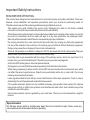
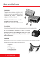
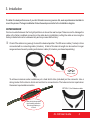
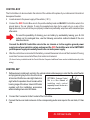
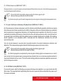
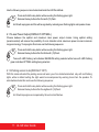
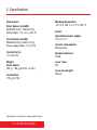
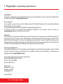
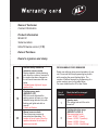
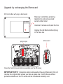
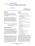
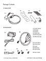
Package Contents
A. Sensor Unit
A2
A3
A4
A1
A6
A5
B. Control Unit
B2
B1
B3
A1 Outer Sensor
A2 Bracket
A3 Screws
A4 Cable ties
A5 Shrinking tube
A6 Adhesive tape
B4
B5
B1 Control Box
B2 Control Set
B3 Level
B4 Wire taps
B5 LED holder
B6 User Guide
AL G9 User Guide, ed. 2009-09-28
COPYRIGHT © 2009 A-ELEKTRONIK
Important Safety Instructions
READ BEFORE OPERATING
This product was designed and manufactured to meet strict quality and safety standards. There are,
however, some installation and operation precautions which you should be particularly aware of.
Therefore read, keep and follow these guidelines during installation and use:
Take special care while installing the sensor head. Damaging the cable or the factory installed
connector on the cable may cause malfunction and will void warranty.
While the sensor is water resistant and intended to be installed on the outside of the vehicle, the control
box and it’s connections must be made and kept in a dry area, preferably the passenger cabin.
Warranty will be deemed invalid if failures are caused by improper installation.
Do not plug more than four outer sensors into the control box. Do not plug any third party equipment
into any of the sockets in the control box. Do not plug any part of the AL G9 into third party equipment.
Doing so may cause fire or damage to the unit and voids warranty.
Since AL G9 operates on a different voltage it is NOT to be mixed with AL G8 components. Doing so
would cause characteristic failure of the unit and voids warranty.
It will take time to get acquainted with the range of the parking sensor, which can vary from 0 to 3
meters, from your car to the obstruction. Therefore rely on your personal judgment.
AL G9 can NOT detect glass or other transparent objects.
During warm-up mode (first 60 seconds of operation) AL G9 functions are limited.
While driving, especially in winter months, dirt and filth can accumulate on the outer sensor lens, which
can affect the sensor's performance. Wipe the lens periodically with a dry or moist cloth. Do not use
cleaning solvents other than water.
Laser signals emitted from AL G9 can cause interference to other laser equipment. If such a case is
detected by the unit the system will reset within few seconds.
If the vehicle where AL system is to be installed is already using another laser system (for instance
laser cruise control, or similar) two systems could interfere with each other. Such vehicles may not be
suitable for use of AL system.
Use of laser products may be regulated by your local laws. Check your local laws before using this
product.
Special caution
AL G9 laser sensor emits an invisible laser beam that can be harmful to sight. Never, under any
circumstances look at the sensor while it is operating.
Safety and Conformity
Electromagnetic compatibility
The AL G9 Guardian is fully in conformity with the requirements of Council Directive 2004/108/EC
Electromagnetic Compatibility (EMC), based on the full compliance of the product with the following
European/International Standards:
Emissions: EN 61000-6-3 (IEC 61000-6-3)
Immunity: EN 61000-6-1 (IEC 61000-6-1)
The labelling of the AL G9 which is affixed on the top of the Outer Sensor and the Control Box housing
meets the requirements of the guideline 2004/108/EC:
The AL G9 Guardian is fully in conformity with the requirements of Automotive EMC Directive
2004/104/EC amended by directives 2005/49/EC, 2005/83/EC, 2006/28/EC and approved by State
Office for Metrology of Republic of Croatia with approval number 10R-02 0004.
Laser safety
The AL G9 is tested and classified as Class 1M laser product in accordance to European and
International Eye safety regulations EN 60825-1 and IEC 60825-1.
Definition: Class 1M-laser products are safe under reasonably foreseeable conditions of operation, but
may be hazardous if the user employs optics within the beam.
An Outer Sensor unit of the AL G9 system is labelled in accordance to regulations:
For products delivered into the United States the following clause applies:
Complies with 21 CFR 1040.10 and 1040.11 except for deviations pursuant to Laser Notice No. 50, dated
July 26, 2001.
Table of Contents
1. Introduction
1
Revision X Improvements
2
2. Main Parts of the Product
3
3. Installation
Installation diagram
4. Usage
4.1 Operating modes
4.1.1 Detection range adjustment
4.1.2 Silent power-up
4.1.3 Laser interference defense (LID) adjustment
4.1.4 LED Dark mode
4.1.5 Laser Power Output
4.1.6 Parking sensor mute
4.2 Additional features
4.2.1 Speaker mute
4.2.2 Restore factory default settings
4.2.3 Manual sensor check
4
7
9
9
9
10
10
10
11
11
12
12
12
12
5. Specifications
13
6. Operation description
14
7. Registration, warranty and service
15
1. Introduction
Thank you for purchasing AL G9 GUARDIAN, a multipurpose parking sensor designed for
your driving comfort by A-ELEKTRONIK, Croatia.
The G9 comprises parts fabricated to military standards and was designed to keep you and
your vehicle safe by enabling effortless parking and greater confidence while driving. As
opposed to classic infra-red sensors that use light emitting diodes AL G9 is equipped with a
laser diode that is used in military range-finders and police speed detectors, the power of
which is one hundred times greater than that of a LED diode. In addition, it incorporates the
new laser detection technology that is a significant improvement in the industry and will ensure
higher precision, more reliability with high resistance to temperature changes and foreign light
interferences, specifically Sun rays.
The G9 works on the 905 nm light frequency. It constantly emits laser signals and recognizes
them if they return reflected from an obstacle, consequently warning the user. Thanks to the
advanced program code the G9 will differentiate the laser signals coming from other laser
sources.
If an AL Driveway Unit (an option) is installed in your driveway or garage the G9 becomes a
driveway light activator and/or a garage door opener.
As we continue to work on developing new products and supply constant improvements to our
existing products we thank you for the support given by this purchase.
AL G9 is patent pending according to PCT/HR2008/000015.
1
AL G9 User Guide
Revision X Improvements
AL G9 superior laser detection is achieved by completely new electronic and computing
design of the reception system. The unit's memory has been doubled enabling new program
features to be added.
The latest hardware revision brings more advancements:
- waterproof connector 1 meter from the sensor for easier installation
- thick shielded cable prevents engine interference and mechanical damage
- cable stress relief is now inside the sensor making it smaller
- optional extension cables available to fit to any length
- improved laser sensitivity (+15%)
- improved power filtering against power line noise
- fully effective from 10V to 17V power supply
- improved parking assistance performance
- even wider angle protection (up to ±12°H ±12°V)
- Control Box now comes with plug in Memocard enabling quick upgrades by end users
IMPORTANT NOTE: The G9 uses lower voltage and less current
consumption and is NOT compatible with AL G8 components.
AL G9 User Guide
2
2. Main parts of the Product
Control Box
The central part and the brain unit of the AL G9. It
includes a processor, a removable Memocard with
upgradeable flash memory, a complex power
supply unit and the following sockets:
1) 4 S sockets for front/rear sensors connection
2) C socket for control set connection
3) USB socket for AL G9 additional feature modules
Outer Sensor
Incorporates emitting and detection circuits: includes one emitting and four reception diodes.
As this unit is installed on the outside of the vehicle, it is specially
protected from water and mechanical damage. Sensor cable is 1 meter
long ending with a waterproof connector. The product set can consist of
one to four outer sensors.
Control Set
A cable with a C connector on one end which should be connected to the C socket of the Control Box.
The other end of the cable consists of controls that include:
on&off switch,
speaker,
two-color light diode,
programming key button,
mute wire for car stereo.
3 AL G9 User Guide
3. Installation
To obtain the best performance of your AL G9 and insure long service life, seek a professional installer to
mount the product. To begin installation follow these steps and refer to the Installation diagram.
OUTER SENSOR
Can be mounted between the front grill partitions or above the rear bumper. Take care not to damage the
cable or the factory installed connector on the cable during installation (cutting the cable or removing the
factory installed connector voids warranty and may cause malfunction).
j
Check if the cable is long enough to reach the desired position. The RX sensor cable (1 meter) is to be
connected with a connecting cable (4 meters). A total of 5 meters in lenght can be reached. Longer
range can be achieved by adding an Extension cable (2,5 meters, purchased separately).
arrow to arrow
To achieve maximum water resistance put a heat shrink tube (included) on the connector. Use a
strong heater for the tube to shrink and conform to connector size. The tube can be torn apart when
the sensor requires disconnection.
OPTION: 2,5 m Extension cable
Heat shrink tube provides
total humidity protection.
We strongly advise you
to use it.
AL G9 User Guide
4
k
Attach the unit using double-sided adhesive tape and a mounting bracket to a position that offers
a clear front (back) view. The mounting bracket can be bent as needed. Make sure the sensor is
installed firmly in order to absorb vibrations that occur while driving, especially if mounted on a
motorbike. For maximum grip use an adhesive tape in combination with the mounting bracket.
If installing sensors behind flat surfaces (plastic bumpers, dens grills) it will be necessary to drill
holes through which the sensor will have unobstructed view of the road. Two circles on the
sketch of the sensor lens represent area
where receiving and emitting diodes are
positioned. These circles must be clear
of obstruction while the rest of the lens
can be covered if needed. Obstructing
surface should not be more than 1 cm
away from the sensor lens, or larger
holes should be drilled to maintain
angle protection.
l
Make sure the sensor is levelled (use a level to check).
5 AL G9 User Guide
CONTROL BOX
The Control Box is to be mounted in the interior of the vehicle at the place of your choice and it should not
be exposed to water.
4
5
Locate access to the power supply of the vehicle (+12 V)
Connect the RED Control Box wire to the positive battery lead and BLACK Control Box wire to the
ground lead or the car chassis. If using the supplied wire taps (to be used only on a wire of the
appropriate size) insure that they are properly locked and preferably wrap them with insulation tape
afterwards.
To avoid the possibility of draining your car battery by accidentally leaving your AL G9
system on for prolonged time, use the following connection method instead of the one
described above:
6
Connect the BLACK Control Box wire to the car chassis or to the negative ground power
supply wire of your vehicle's system and connect the RED Control Box wire to the SWITCHED
positive power supply wire usually found in the car radio power supply.
After the control box is connected to the battery, connect the sensor into one of the S sockets. If having
more than 1 sensor connect all of them, their order is not relevant.
(1A fuse is factory installed inside the Control Box but if required additional fuses can be installed externally in the
wiring.)
CONTROL SET
7
Define where to install each control in the vehicle interior while keeping in mind that the on&off switch
and programming key button should be close
OPTIONAL: If using a Control
at hand and that the two-color light diode is in
Set in a Box instead of
sight while the speaker should remain within
installing each control
hearing range of the driver. Use a LED holder
separately mount the box in a
supplied with the installation accessories
clearly seen position.
when installing a two color LED diode.
8
9
Connect the C connector to the C socket of the Control Box.
Connect the blue car radio mute wire to the corresponding audio mute input on the car radio, if it has
one.
AL G9 User Guide
6
Installation diagram
on & off switch
programming key button
black
speaker
two color LED
mute wire
a battery
red
4. Usage
Turn on your AL G9 set. The activation is followed by an intermittent sound coming from the speaker and
alternating red and green flashing diode lights. While active the green light will flash once every second.
With every activation the set runs a self-test; if the set has not been connected properly or has a
malfunction, the red diode will light up accompanied by a warning tone. When an obstacle is detected your
AL G9 will warn you with red diode flashes and audible signals that will become faster as the obstacle gets
closer to the outer sensor. You will also be warned with fast red flashes and speaker tones in case of laser
interference detection. More on operation modes and audio-visual signals can be found on page 14.
AL G9 has 6 user selectable operating modes which are set to optimal default values but can be modified
by using the programming key button at any time during the operation of AL G9. After been modified
operating mode will remain permanently written in the memory of the processor. Some additional features
will be introduces further on.
4.1 Operating modes
4.1.1 Detection range adjustment (DEFAULT: LEVEL 2)
Before using the parking sensor in driving conditions it should be tested with a piece of paper or another
object. A warning tone will be heard, accompanied by the red flashing light as you bring the paper or object
closer to the sensor. If needed, the detection range (which can vary from 0 to 3 meters) can be adjusted to
four different levels by using the programming key button. Use the following sequence for reprogramming:
3
Press and hold the key button while counting the flashing green light.
Release the key button after the third (3) flash.
AL G9 will reprogram accompanied by red and green flashing lights and speaker tones. Long
tones coming from the speaker during reprogramming symbolize four different detection levels:
1 tone for LEVEL 1 (short mode);
2 tones for LEVEL 2 (medium mode);
3 tones for LEVEL 3 (long mode);
4 tones for LEVEL 4 (extra long mode).
The detection range levels alternate and you will need to reprogram the set several times before reaching
the desired setting.
9 AL G9 User Guide
4.1.2 Silent power-up (DEFAULT: OFF)
During activation, only red and green indicator lights will flash without sounds. Use the following sequence
to activate/deactivate this feature:
5
Press and hold the key button while counting the flashing green light.
Release the key button after the fifth (5) flash.
AL G9 will reprogram and this will be signalled by red and green flashing lights and speaker tones.
4.1.3 Laser interference defense (LID) adjustment (DEFAULT: 4 SEC)
AL G9 possesses an advanced program code for detecting and deflecting possible interference signals
from other sources of laser emissions on the 905 nm frequency. When a constant interference is detected
and recognized as an aggressive disturbance for the parking sensor operation, AL G9 will try to ensure
maintaining its reliable performance. During this time the user will be warned by a four second tone from
the speaker and a red flashing light that a parking sensor operation has become unreliable. If the parking
sensor operation is not recovered within 4 seconds and the interference continues the unit will
automatically reset.
You can choose between 4 seconds and 8 seconds duration of eventual interference detection and
deflection. This mode can be programmed with the following sequence on the key button:
8
Press and hold the key button while counting the flashing green light.
Release the key button after the eighth (8) flash.
AL G9 will reprogram accompanied by red and green flashing lights and speaker tones. A short
tone coming from the speaker during reprogramming indicates the 4 sec mode being selected while the
long tone indicates the 8 sec mode. The limit duration settings alternate so please repeat the sequence to
return to the previous state.
4.1.4 LED Dark mode (DEFAULT: OFF)
To prevent the green light from flashing every second during normal operation, you can activate the LED
Dark mode. The green light will stop flashing after the warm-up period (60 seconds after the power-up) if
this mode is activated.
AL G9 User Guide
10
Use the following sequence to activate/deactivate the LED Dark Mode:
10
Press and hold the key button while counting the flashing green light.
Release the key button after the tenth (10) flash.
AL G9 will reprogram and this will be signaled by red and green flashing lights and speaker tones.
4.1.5 Laser Power Output (DEFAULT: OPTIMAL)
Choose between the optimal and maximum laser power output modes. Using optimal setting
(recommended) will reduce the possibility of error detection while maximum power insures maximum
range and energy. To reprogram this mode use the following sequence:
13
Press and hold the key button while counting the flashing green light.
Release the key button after the thirteenth (13) flash.
Tone with LED flashing red indicates MAXIMUM setting selected while tone with LED flashing
green indicates OPTIMAL setting being selected.
4.1.6 Parking sensor mute (DEFAULT: OFF)
With this mode activated the parking sensor will warn you of an obstacle detected only with red flashing
lights, while in default setting the light would be accompanied by warning tones from the speaker. To
activate/deactivate this mode use the following sequence:
18
Press and hold the key button while counting the flashing green light.
Release the key button after the eighteenth (18) flash.
AL G9 will reprogram accompanied by three short red flashes.
11 AL G9 User Guide
4.2 Additional features
4.2.1 Speaker mute
1
The key button is useful in city driving as a single 1 second press will switch the speaker off
and further parking sensor warnings will be given just by red flashing lights.
This setting lasts until the set is turned off.
4.2.2 Restore factory default settings
Did you forget which features you programmed into your system? Use this simple programming sequence
to restore factory default settings:
15
Press and hold the key button while counting the flashing green light.
Release the key button after the fifteenth (15) flash.
AL G9 will reprogram accompanied by constant green light and longer speaker tone.
Automatic sensors check
While restoring factory default settings the unit will count and memorize the number of
sensors connected to the system. On each subsequent power-up during the self-test
process the unit will check if all memorized sensors are present and operational. If one or
more of them is disconnected or not operational you will be warned by five 2 seconds long
tones and red flashes during first 15 seconds of operation.
NOTE: In order to memorize the new setup initiate this setting after installation of every new
sensor.
4.2.3 Manual sensor check
To manually check the number of sensors connected and operating in the system use the following
programming sequence:
20
Press and hold the key button while counting the flashing green light.
Release the key button after the twentieth (20) flash.
The number of long tones coming from the speaker shows how many sensors are found
connected.
12 AL G9 User Guide
5. Specifications
Dimensions:
Outer Sensor (LxHxW)
43x20x50 mm (1,7x0.8x2.0 in)
Cable length: 1 m + 4 m (16.4 ft)
Control Box (LxHxW)
85x22x40 mm (3.3x0.8x1.6 in)
Power supply cable: 1 m (3.3 ft)
Control Set (L)
1,5 m (4.9 ft)
Weight:
Outer Sensor
105 g + 160 g (0.26 lb + 0.4 lb)
Control Box
110 g (0.27 lb)
Specifications are subject to change without notice.
13 AL G9 User Guide
Working temperature:
-20 °C to +60 °C (-4 °F to 140 °F)
Power:
Operational power supply
10 V to 17 V
Current consumption
600 mA max.
Speaker loudness:
90 dB
Laser class:
1M
Laser wavelength:
905 nm
6. Operation description
Operation :
Activation mode
1 second following power-up; self-test
Warm-up mode
60 seconds following the Activation mode; during warm-up mode AL G9 functions are limited.
The end of a warm-up mode is signaled with a green LED flash and a tone from the speaker.
Search mode
Searching for obstacles; Other functions
LED & sound signals:
LED flashing green
Normal operation, LED flashes green every second
LED flashing red + tone
Obstacle found
LED constant red + tone
Interference detected; LID activated
LED constant red + 1 beep
Faulty operation; low voltage, check vehicle power supply
LED constant red + 2 beeps
Faulty operation, cables unplugged or defective unit, check cables
LED constant red + 3 beeps
Warning sensor unplugged, not properly mounted or a defective sensor, check sensor
LED flashing red + beeps during first 15 seconds of operation
Automatic sensor check failed, check sensor connections. If adding or removing sensors
perform code 15 (restore factory defaults).
AL G9 User Guide
14
7. Registration, warranty and service
Registration
To become a Registered owner of the AL G9 please send a registration inquiry no later than 30 days from
the date of purchase to [email protected].
Why to register?
If you register, you get once a year free Memocard with the latest firmware sent to your address directly
from the factory on your request.
Only registered users will receive newsletters and get special discounts.
To find out if there is a program code upgrade available for your system, send an inquiry to
[email protected] or contact your local dealer.
Warranty
The manufacturer guarantees that the product is fully functional. During production and before delivery it
undergoes numerous quality checks. Nevertheless, a limited two years warranty will apply, valid from the
date of the first purchase. If you have not registered your product in case of warranty claim you are
required to show an original receipt with a visible date of the purchase and a warranty card authorized by
the dealer. The warranty terms are defined in the warranty card, here included.
Servicing and Support
If uncertain whether your AL G9 is working correctly please check Operation description, page 14 of this
manual. If it does not give you a solution to your problem contact your local dealer or our Service and
Support center at [email protected].
Service and support provided by the manufacturer:
A-ELEKTRONIK, Zagreb, Croatia
Phone: +385 1 364 3890
www.a-elektronik.hr
Wholesales:
Radikal d.o.o. (ltd.)
Sesvete - Croatia
[email protected]
www.alg9.com
15 AL G9 User Guide
Name of Customer
Contact information
Product information
Model ID
Serial numbers
Initial firmware version (F/W)
Date of Purchase
Dealer's signature and stamp
15
Restore factory defaults &
memorize sensors setup
Restore defaults. Initiate restoring
each time the number of sensors in
the system has been changed so
the unit would memorize the new
setup.
Constant green light and longer
speaker tone.
18
Parking sensor mute
(DEFAULT: OFF)
With this mode activated the
parking sensor will warn you of an
obstacle being detected only with
flashing red lights and with no
sounds.
3 short red flashes.
20
Manual sensors check
Check how many sensors is
connected and operating. The
number of tones coming from the
speaker indicates the number of
sensors connected.
PROGRAMMING CODES REMINDER
Select new settings during normal operation of your
unit. Press and hold the programming key button
while counting the green flashing lights. The
number of flashes required for programming of a
certain mode is given in the table below.
For more details see the G9's User Guide.
Nu. of
flashes
1
3
Mode that will be changed
& audio-visual signals
Speaker mute
This setting lasts until the set is
turned off.
Parking detection range
(DEFAULT: LEVEL 2)
Reprogramming tones:
1 tone - LEVEL 1 (short)
2 tones - LEVEL 2 (medium)
3 tones - LEVEL 3 (long)
4 tones - LEVEL 4 (extra long)
OFF)
Silent power-up (DEFAULT:
5
8
During activation only red and
green indicator lights will flash
with no sounds.
Red and green flashing lights
and 6 short speaker tones.
Laser interference defense (LID)
adjustment (DEFAULT: 4 SEC)
Choose between 4 sec and 8 sec
duration of LID.
Red and green flashing lights and 4
short speaker tones. If a fifth (5)
tone coming from the speaker is
short than the 4 sec mode was
selected while the long tone
indicates that the 8 sec mode was
selected.
10
13
LED Dark mode (DEFAULT: OFF)
Prevent the green light from
flashing every second. The green
light will stop flashing 60 seconds
after power-up.
Red and green flashing lights and 6
short speaker tones.
Laser Power Output (DEFAULT:
OPTIMAL)
Using «optimal setting»
(recommended) will reduce the
possibility of error detection while
«maximum power» insures
maximum range and energy.
Tones with LED flashing RED
indicate MAXIMUM setting selected
while tones with LED flashing
GREEN indicate OPTIMAL setting
being selected.
- ELEKTRONIK
Zagreb, Croatia
Phone: +385 1 364 3890
www.a-elektronik.hr
Manufacturer's Service and Support center:
The manufacturer - by means of its sales organization, representative
or distributor - guarantees this product against manufacturing defects
and guarantees after-sales servicing for two (2) years from the
original purchase date.
Should the product fail to work or show a manufacturing defect within
the warranty period A-ELEKTRONIK - by means of its sales
organization, representative or distributor - will take the necessary
actions to restore the perfect functioning of the product. To repair it or
to replace is at discretion of A-ELEKTRONIK.
Should the product fail to work or show a manufacturing defect, the
consumer shall contact A-ELEKTRONIK Service Center or distributor
for further service arrangement. When taken to a service company
the product must be accompanied with the warranty card and the
official purchase receipt.
It is necessary that the warranty card has been correctly and
completely filled out at the time of the original purchase. If not, the
warranty may not be in effect.
This warranty shall not apply to the following:
1) Normal wear and tear of the product and/or its parts.
2) Accidents, which occur during shipping and handling, and damage
resulting from such accidents.
3) Malfunction or damage due to a product misuse, or negligence by
the customer, or any use of the product other than that described in
user's guide.
4) Damage caused by incorrect installation.
5) Product is rebuilt, repaired or with adaptation made by non-certified
person, as well as by installation, modification or operation with
violation of technical specifications and/or safety regulation.
6) Products with serial numbers which have been changed, tampered
with or removed.
7) Any damage, failure or loss caused by accident, misuse, and any
other failure not directly related to a defect of the product.
The warranty does not cover installation and dismantling fees, nor
shipping costs.
Note: This warranty shall not be applicable, if the required
information in the warranty card is not completely filled in or if the
content is revised or modified in any way.
For further information please visit the website www.alg9.com, or
write to [email protected] .
Warranty Terms and Conditions
Upgrade by exchanging the Memocard
RX Control Box with plug in Memocard
SN: XXXXX
Remove Control Box protective
label but do not remove small
serial number label
Unscrew 5 screws and open the box
Unplug the old Memocard and plug
in the new one
plug in spot
Memocard
Close the Control box and stick a new label over the 5th screw
IMPORTANT NOTE: 1 protective label is delivered with every Memocard. Do not
remove the original label unless you have a spare one. Control boxes without
protective labels over the 5th screw will be considered warranty void.