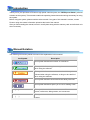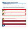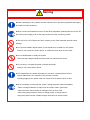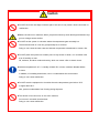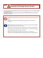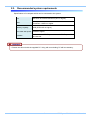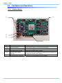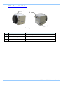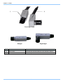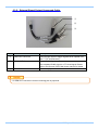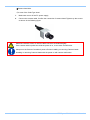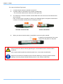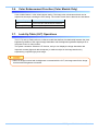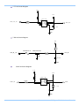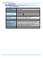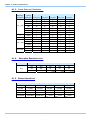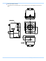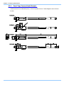
1
IDP-Express R2000 The copyright of this manual is held by Photron LIMITED. Product specifications and manual contents can change without advanced notification. This manual was created taking every possible measure to ensure the accuracy of its contents. However, if you find a section which is unclear, a mistake, or an omission, please contact Photron LIMITED using the contact information provided at the end of the manual. Photron LIMITED bears no responsibility for the results of using the product or from following the instructions in this manual. Introduction Thank you for your purchase of Photron’s high-speed camera system, the “IDP-Express R2000” (referred to below as the system). This manual contains the operating instructions and warnings necessary for using the system. Before using the system, please read the entire manual. If any part of this manual is unclear, contact Photron using the contact information printed at the back of the manual. After you finish reading the manual, store it in a safe place along with the warranty card and refer back to it when necessary. Manual Notation The following icons and symbols are used in the explanations in this manual. Icon/Symbol Description This symbol indicates the location of a reference. This symbol indicates supplementary items to be aware of when using the software. This symbol indicates instructions that should always be followed when using the software, or things to be careful of when using the software. This symbol indicates content that should always be read. This symbol indicates a space you to use for making notes. " [ This symbol is used to indicate the names of items on a " screen, references, dialog names, and connectors. ] This symbol is used to indicate menu names, and sub-menu names. Using the Manual This section explains the layout of the manual. Introduction The introduction explains the manual and safety precautions. Chapter. 1 Overview This chapter gives an overview of the system and an explanation of its features. Chapter. 2 Setup This chapter gives an overview of the components that make up the system. It also explains basic keypad operation and a list of items that should be checked before using the system. Chapter. 3 Recording This chapter explains operations related to recording. Chapter. 4 Product Specifications This chapter explains the system’s specifications. Chapter. 5 Warranty This chapter explains about the warranty. Chapter. 6 Contacting Photron This chapter lists the contact information to use when contacting Photron if the system malfunctions or if a portion of the manual is unclear. Using the System Safely and Correctly In order to prevent injury to yourself and others, and to prevent damage to property, carefully observe the following safety precautions. Photron has given its full attention to the safety of this system. However, the extent of damage and injury potentially caused by ignoring the content of the safety precautions and using the system incorrectly is explained next. Please pay careful attention to the content of the safety precautions when using the system. Warning Caution This symbol indicates actions that carry the risk that a person could receive a serious injury. This symbol indicates actions that carry the risk that a person could receive a moderate injury, or that damage to physical property might occur. The safety precautions to be observed are explained with the following symbols. This symbol indicates actions that require caution. This symbol indicates actions that are prohibited and must be avoided. This symbol indicates actions that must always be performed. Warning ■ Before operating the unit, please read the manuals of PC and other peripherals thoroughtly, and retain for future reference. ■ When connect and install this unit to PC and other peripherals, please make sure to turn off the device power supply, pull out the plugs, and remove the concerning cables. ■ This unit is for a PCI Express bus only. Inserting to any other extended slots will cause damage. ■ Do not insert metallic objects inside, or pour liquids such as water on, the system. Doing so can cause fire, electric shock, or malfunction from short circuit or heat. ■ Do not disassemble or modify the system. There are high voltages inside the system that can cause electric shock. ■ Do not plug in or unplug the power cord with wet hands. Doing so can cause electric shock. ■ This chapter lists the contact information to use when contacting Photron if the system malfunctions or if a portion of the manual is unclear. Not fully plugging in the power cable can cause fire from electric shock or heat. ■ When something is wrong with the system, unplug the power cable immediately. - When a foreign substance or liquid, such as metal or water, gets inside. - When the outer case is broken or damaged, such as from a fall. - When the system produces smoke, a strange smell, or strange sound. Using the system in these conditions might cause a fire or electric shock. Caution ■ Do NOT touch the card edge connector part of this unit. It may cause a loose connection or malfunction. ■Please consult to us in advance, When you perform shoot by which laser light and direct rays go into a image sensor surface. ■ Do NOT set the system in a location where the temperature gets unusually hot. The trunk and inside of a car can get especially hot in summer. Doing so can cause the outer case and internal components to deteriorate or cause a fire. ■ Do NOT place the system in a location prone to oily smoke or steam, or in a location with a lot of humidity or dust. Oil, moisture, and dust conduct electricity, which can cause a fire or electric shock. ■ Ambient temperature 5-45° C, humidity 20-80% RH or lower, maximum altitude 2000m or lower. In addition, if exceeding these limits, use in a condensation-free environment. Doing so can cause malfunction. ■ Do NOT store the equipment in a location where the temperature goes below -20°C or higher than 60°C. Also, prevent condensation from forming during shipment ■ This device is for indoor use, do not use it outdoors. Do not use in a location that has dust. Doing so can cause malfunction. Cleaning of the Image Sensor Surface Electrostatic Discharge (ESD) events may cause immediate and unrecoverable damage to the image sensor. Please read the following instructions and take EXTREME CARE when cleaning the image sensor surface. ■ALWAYS take appropriate anti-static precautions when cleaning or working near the image sensor. ■DO NOT use any form of cleaning equipment using electrostatic or ‘charged fiber’ technology. ■Please discharge any electrostatic build up in your body by touching a grounded metallic surface before working near the camera sensor. ■Very gently , use only clean and dry air to remove dust from surface of the image sensor. ■To remove stubborn contamination use the highest grade (e.g. VLSI grade) pure isopropyl alcohol (IPA) with optical wipes of ‘clean room’ grade. ■Extreme care must be taken! Gently wipe across the sensor in a single action. (DO NOT rub to avoid abrasive damage to delicate optical coatings on the glass surface.) About recording data ■Since this product records and transfers the images with a high speed directly to the PC memory, it is occurable for Missing Frames (miss recording). ■When Photron FASTCAM Viewer is terminated by user, or aborts accidentally, the preserved memory will be released and the images in it will disappear. Table of Contents Chapter. 1 1.1. 1 Product Overview and Features .............................................................................. 2 Chapter. 2 2.1. 2.2. 2.3. Overview Setup 3 System Components and Accessories .................................................................... 4 Recommended system requirements ...................................................................... 5 Part Names and Operations .................................................................................... 6 2.3.1. Grabber Board ............................................................................................ 6 2.3.2. Camera Head Portion ................................................................................. 7 2.3.3. Camera Cable.............................................................................................. 9 2.3.4. External Signal Input Compound Cable .................................................... 10 2.3.5. External Signal Output Compound Cable ................................................. 11 2.4. Device Connections ............................................................................................... 12 2.4.1. Connecting a Camera Head ..................................................................... 12 Chapter. 3 Recording 15 3.1. 3.2. 3.3. Selecting the Frame Rate ...................................................................................... 16 Selecting the Resolution ........................................................................................ 16 Selecting the Shutter Speed .................................................................................. 17 3.3.1. Changing SHUTTER LOCK ...................................................................... 17 3.4. Selecting the Trigger Mode .................................................................................... 18 3.4.1. START Mode ............................................................................................. 18 3.4.2. CENTER Mode ......................................................................................... 18 3.4.3. END Mode................................................................................................. 19 3.4.4. MANUAL Mode ......................................................................................... 19 3.4.5. RANDOM Mode ........................................................................................ 19 3.5. White Balance Adjustment (Color Models Only) .................................................... 20 3.5.1. Using Preset White Balance (Color Models Only) .................................... 20 3.5.2. Using User White Balance (Color Models Only) ....................................... 20 3.6. Color Enhancement Function (Color Models Only) ............................................... 21 3.7. Look-Up Table (LUT) Operations ........................................................................... 21 3.8. Edge Enhancement Function ................................................................................ 22 3.9. Setting the Sensor Gain ......................................................................................... 22 3.10. Input/Output Signal Types...................................................................................... 23 3.10.1. External Signal Input Compound Cable .................................................... 23 3.10.2. External Signal Output Compound Cable ................................................. 23 3.11. Using External Triggers.......................................................................................... 24 3.11.1. Inputting an External Trigger Signal .......................................................... 24 3.11.2. Outputting External Trigger Signals .......................................................... 26 3.12. About Record Time(Record Frames) ..................................................................... 26 Chapter. 4 Product Specifications 27 4.1. Specifications ......................................................................................................... 28 4.1.1. Product Specifications............................................................................... 28 4.1.2. General Specifications .............................................................................. 29 4.1.3. Frame Rate and Resolution....................................................................... 30 4.1.4. Selectable Resolution List......................................................................... 30 4.1.5. Shutter Speed List..................................................................................... 30 4.2. Dimensions ............................................................................................................ 31 4.2.1. Grabber Borad .......................................................................................... 31 4.2.2. Camera Head ............................................................................................ 32 4.2.3. Pencil Type Camera Head (Straight) ........................................................ 34 4.2.4. Pencil Type Camera Head (Right angle) .................................................. 35 Chapter. 5 5.1. 37 About the Warranty ................................................................................................ 38 Chapter. 6 6.1. Warranty Contacting Photron 39 Contact Information................................................................................................ 40 Chapter. 1 Overview 1.1.Product Overview and Features 1 IDP-Express R2000 Hardware Manual Chapter. 1 Overview 1.1. Product Overview and Features This product is applicable for engineering research and development as a powerful tool in various fields, such as in designing, manufacturing, and the quality controling, etc. Moreover, it is also suitable for a compact, flexible and extendible built-in system, or a PC-platformed systematization application,. The device can connects and drives two micro-sized camera heads that can work under 2,000 fps with a resolution of 260,000 pixels. The image data is transmitted and recorded in the main memory of PC in real time. It makes it possible to process a high-speed image grabbing easier with this architecture. Furthermore, the construction of a high-speed imaging system in the software level becomes possible. The device can be used not only as a simple high-speed camera system on a PC platform; it can also work as a measurement apparatus combining with other peripheral devices. Moreover, it is competent for manufacture, inspection equipment, and a system component as well. Tripod is not supplied as a default accessory. IDP-Express High Speed Frame grabber is already installed into PC while shipped. 2 Chapter. 2 Setup 2.1. System Components and Accessories 2.3. Recommended system requirements 2.4. Part Names and Operations 2.4. Device Connection 3 IDP-Express R2000 Hardware Manual Chapter. 2 Setup 2.1. System Components and Accessories The system's standard components are listed below. Remove the components from the packaging and check the system. 1. Grabber Board (PCI Express Board) 1 2. Camera Head(s) (with C mount adapter) Cube Type / Pencil Type (depends on configuration) 3. Camera Cable(s) (7m) Cube Type / Pencil Type (depends on configuration) 4. Tripod adaptor (depends on configuration) Cube Type / Pencil Type 5. External signal input compound cable 1 6. External signal output compound cable 1 7. Grabber Board Power supply cable 1 8. FASTCAM Series Setup Disk (Driver/Application CD) 1 9. IDP-Express R2000 Hardware Manual (This Manual) 1 10. Photron FASTCAM Viewer User's Manual 4 1 2.2. Recommended system requirements Specifications of a computer which can be connected to the system. OS Windows XP 32bit Professional (SP3 or higher) CPU Core2Duo 1.86GHz or higher Memory Capacity 4GB (DDR2-800 or higher) Free hard disk space 100GB or higher Interface At lease one x8 PCI Express slot or x16 PCI Express slot be reserved. Please use this unit with the supplied PC. Using with an excluding PC will lose warranty. 5 IDP-Express R2000 Hardware Manual Chapter. 2 Setup 2.3. Part Names and Operations 2.3.1. Grabber Board ① ④ ② ③ ⑤ No. Connector Description ① Special connector Use a special cable to connect to camera head. ② I/O Cable Connector (OUT) Connect to a trigger output I/O cable. ③ I/O Cable Connector (IN) Connect to a trigger input I/O cable. ④ Internal Power Supply The power supply of the addition is supplied from the inside of PC. Conector (Connector for FDD power supply) PCI Express bus connector Insert to a PC PCI-Express bus (x8 or higher). ⑤ 6 2.3.2. Camera Head Portion ① ② ③ Cube type head No. Part Name Explanation ① Lens mount Connects the Camera Head to a Lens with the C-mount. ② Camera Head output connector Connects the Camera Head to the Grabber board with the ③ Serial number label dedicated cable. Shows the product serial number. 7 IDP-Express R2000 Hardware Manual Chapter. 2 Setup ① ② Pencil type head Straight No. Right angle Part Name Explanation ① Lens mount Connects the Camera Head to a Lens with the C-mount. ② Serial number label Shows the product serial number. 8 2.3.3. Camera Cable A cable that connecting the camera head with the frame grabber is necessary. For a cube-type camera head, the cable connects the camera head with the frame grabber. For a pencil-type camera head, the cable connects between the frame grabber and the cable that fixed on camera head. When securing the camera cable, do not bend it R50 or lower. Always secure the camera cable externally in one location within 60 cm of the connector. 9 IDP-Express R2000 Hardware Manual Chapter. 2 Setup 2.3.4. External Signal Input Compound Cable ① ② ③ No. Name Description ① T-SW IN Connector A trigger signal input connector for receiving a switch-in ② T-TTL IN Connector A trigger signal input connector for receiving a TTL level ③ SYNC IN Connector An external synchronizing signal is inputted via this signal. signal. connector. 10 2.3.5. External Signal Output Compound Cable ① ② ③ No. Name Description ① TRIG OUT Connector Pass-through output of trigger signal that be inputted from the「T-TTL IN Connector」 ② SYNC OUT Connector Output SYNC Signal The outputted SYNC signal is a TTL level signal. Please refer to the Photron FASTCAM Viewer manual for details. ③ GEN OUT Connector Not in use.(※) A GEN OUT connector’s function mounting plan is proposed. 11 IDP-Express R2000 Hardware Manual Chapter. 2 Setup 2.4. Device Connections 2.4.1. Connecting a Camera Head Follow the procedure below to connect a Camera Head to the Grabber Board. ■ Frame grabber Board side. 1. Make sure to turn off the PC power supply, 2. Connect the camera cable. Confirm the connection of camera head and the Grabber Board respectively. tightens up the screws as shown in the following figure. 12 ■Camera head side. ◇In case of the Cube Type head 1. Make sure to turn off the PC power supply, 2. Connect the camera cable. Confirm the connection of camera head. Tightens up the screws as shown in the following figure. Make sure that the screws of camera cable connector be fastened tightly. If the camera cable is pulled out while the power is on, it can cause a malfunction. Always turn the Camera Controller's power off when installing or removing Camera Heads. Installing or removing Camera Heads with the power on will cause a malfunction. 13 IDP-Express R2000 Hardware Manual Chapter. 2 Setup ◇In case of the Pencil Type Head 1. 2. It checks that the camera controller is turned off. A camera cable is connected to the camera controller side. * The connection method is the same as a cube type head. 3. The cable from a camera controller and the cable which has come out of the camera head are connected. Each connector part is checked, as shown in the following figure a red point is united and it connects. If it inserts normally, there is a feeling of a click. ■Camera Controller Side 4. ■Camera Head SIde When you remove camera cable, it is possible to remove to pull to outside. It draws out in the direction of an arrow. Press down the place of a red point. Always secure the camera cable by tightening the screws attached to the camera cable's connector. If the camera cable is pulled out while the power is on, it can cause a malfunction. Always turn the Camera Controller's power off when attaching or removing Camera Heads. Adding or removing Camera Heads with the power on can cause a malfunction. 14 Chapter. 3 Recording 3.1. Selecting the Frame Rate 3.2. Selecting the Resolution 3.3. Selecting the Shutter Speed 3.4. Selecting the Trigger Mode 3.5. White Balance Adjustment (Color Models Only) 3.6. Color Enhancement Function (Color Models Only) 3.7. Look-Up Table (LUT) Operations 3.8. Edge Enhancement Function 3.9. Setting the Sensor Gain 3.10. Input/Output Signal Types 3.11. Using External Triggers 3.12. About Recording Time(Recording Frames) 15 IDP-Express R2000 Hardware Manual Chapter. 3 Recording 3.1. Selecting the Frame Rate With the system, you can record images from 50 to 2,000 fps using the full 512x512 pixel resolution of the image sensor. For frame rates higher than 2,000 fps, high-speed photography is achieved by limiting the read area of the image sensor. For frame rates over 2,000 fps, the resolution is automatically set to the maximum available at that frame rate. For details, see "4.1.3. Frame Rate and Resolution", page 30. 3.2. Selecting the Resolution With the system, you can record images with a maximum size of approximately 260,000 pixels using the high-speed image sensor, which has a maximum size of 512x512 pixels. You can also record at even faster frame rates or reduce the amount of image data to make even longer recordings by limiting the resolution according to the application. For more information of relation between Frame Rate and Resolution, refer to "4.1.3. Frame Rate and Resolution", page 30. 16 3.3. Selecting the Shutter Speed With the system, the shutter speed is independent of the frame rate, and you can control the exposure timing one frame using the electric shutter. By making an exposure that is of a shorter period than the frame rate, high-speed objects can be recorded blur-free. Shutter speed can be set from 1/frame sec to a maximum of 1/160,000 s (approximately 6.2 us). The procedure for selecting the shutter speed is explained here. For more information of shutter speed, refer to “4.1.5. Shutter Speed List”, page 30. 3.3.1. Changing SHUTTER LOCK By switching between [ON] and [OFF] on the Photron FASTCAM Viewer, the shutter speed value first used when the frame rate is changed can be set. ON: Changing the frame rate does not change the shutter speed, it maintains the current setting. OFF: Changing the frame rate automatically sets the shutter speed to 1/frame s. 17 IDP-Express R2000 Hardware Manual Chapter. 3 Recording 3.4. Selecting the Trigger Mode With the system, in order to reliably capture high-speed phenomena, many kinds of trigger modes have been made available. These trigger modes are explained next. There are seven types of trigger modes which are listed below. - START - CENTER - RANDOM CENTER 3.4.1. - END - MANUAL - RANDOM - RANDOM MANUAL START Mode START mode is a trigger mode where recording starts the instant the trigger is input, the scene is recorded until the memory is full, and then recording ends. This mode is suitable for taking images of high-speed phenomena when what will happen, and when it happens, is known in advance. For example, in a situation with a maximum useable memory of two seconds of recording, two seconds of high-speed video is saved immediately after the trigger is input. 3.4.2. CENTER Mode CENTER mode is a trigger mode where an equal amount of content recorded before and after the trigger is input is saved to memory. This mode is suitable for viewing before and after an important instant. For example, in a situation with a maximum useable memory for two seconds of recording, one second before and one second after the trigger was input is recorded for a total of two seconds of high-speed video. 18 3.4.3. END Mode END mode is a trigger mode where the content recorded immediately before the trigger is input is saved to memory. This mode is suitable for recording a high-speed phenomenon where it is hard to predict when the important action will start and stop. For example, in a situation with a maximum useable memory for two seconds of recording, the two seconds of high-speed video immediately before when the trigger was input are saved. 3.4.4. MANUAL Mode MANUAL mode is a trigger mode, similar to CENTER mode, where the content recorded before and after the trigger is input is saved to memory, but the proportion of time before and after the trigger can be set as required. For example, in a situation with a maximum record time of two seconds, 0.5 seconds before and 1.5 seconds after the trigger is input are recorded and saved, a total of two seconds of high-speed video. 3.4.5. RANDOM Mode RANDOM mode is a trigger mode where each time a trigger is input only a predetermined number of frames are saved to memory. For example, this function is convenient for a subject which is an irregular and repeated phenomenon which can have a trigger output produced for each cycle or occurrence. The number of frames recorded each time the trigger is input can be set as desired, in one frame increments, from one frame to the maximum of all the recordable frames available. 19 IDP-Express R2000 Hardware Manual Chapter. 3 Recording 3.5. White Balance Adjustment (Color Models Only) On digital video cameras, photographing white as pure white is described as "having the appropriate white balance." On the system's color models as well, in order to take images with the correct color representation, the white balance must be adjusted for the color temperature of the light source used. The intensity of each color, R, G, and B, can be adjusted on this system. By adjusting the balance of those three colors to match the light source used, the appropriate white balance can be achieved. Two methods are available for adjusting the white balance, preset and user-editable white balance. These methods are explained in this section. 3.5.1. Using Preset White Balance (Color Models Only) With the system, there are two types of white balance presets (5100K, 3100K) for use with common light sources. The suggested color temperature for these presets is listed below. 5100K (Daylight, Outdoors) 3100K (Halogen Light Source) 3.5.2. Using User White Balance (Color Models Only) Each Camera Head can be assigned a user white balance setting in order to achieve the most appropriate white balance for the light source used and the conditions during recording. The values set here are stored for each camera head in the Camera Controller's internal memory as a user preset, and the values can be loaded by selecting USER. 20 3.6. Color Enhancement Function (Color Models Only) Color models feature a color enhancement setting. The image color enhancement level can be adjusted in two steps, including the OFF setting. The content of each item is listed in the chart below. Menu Display OFF x1 3.7. Contents Turns the color enhancement mode off (LEVEL2) Sets x1 (default) color enhancement Look-Up Table (LUT) Operations The LUT (Look-Up Table) refers to a reference table that defines the relationship between the pixel brightness gradation of the original image data taken and the brightness gradation displayed on a computer screen or video monitor. The system contains a Software LUT function, and you can display the image data taken with improved contrast (light and dark sharpness) or make an object in the image stand out by emphasizing a specified gray level range. When an image is saved with its brightness converted with the LUT, the image saved is the image that has had its brightness converted. 21 IDP-Express R2000 Hardware Manual Chapter. 3 Recording 3.8. Edge Enhancement Function With the system's edge enhancement setting, you can enhance the edges in the recorded image in three steps. Menu Display OFF 3.9. Contents Edge enhancement off. LEVEL1 Edge enhancement set to weak. LEVEL 2 Edge enhancement set to medium. LEVEL 3 Edge enhancement set to strong. Setting the Sensor Gain The sensor gain setting adjusts the amplitude voltage inside the sensor. By increasing this setting, when recording in low light, the signal is amplified and the camera can take a higher gain (brighter) image. However, by amplifying the signal, the noise component also increases, resulting in decreased image quality, or more noise. The sensor gain can be set in two steps according to the object being recorded. The content of each item is listed in the chart below. Menu Display Contents x1 Sets the sensor gain to standard. x3 Sets the sensor gain to 3x. 22 3.10. Input/Output Signal Types With the system, many signals can be input and output through the BNC connectors. Signals that can be input and output from the BNC connectors are listed below. A signal other than the specified signal must not be input to the various connectors. Use extreme caution as there is a risk of damage to both devices, the input device and the output device. 3.10.1. External Signal Input Compound Cable ◆T-TTL IN Connector While working in trigger waiting state or under ENDLESS trigger mode, an outputted pulse signal is recognized as a trigger signal. As a result, record action will start / end according to current recording mode. An input voltage of 0V~+12V(H level +4.5V~+12V), positive/negative polarity, and a more than 50 nsec trigger time are preferred. A working current of 10mA~25mA is recommended (Max current is 25mA). ◆T-SW IN Connector While working in trigger waiting state or under ENDLESS trigger mode, a shield and center pin connection of BNC cable will be recognized as a trigger signal. Do NOT contact the center pin with other pins while operating since a voltage is always applied to the center pin. ◆SYNC IN Connetor Pulse signal inputted from other devices is recognized as a synchronized signal. An input voltage of 0V~+12V(H level +4.5V~+12V), positive/negative polarity, and a more than 50 nsec trigger time are preferred. A working current of 10mA~30mA is recommended (Max current is 30mA). 3.10.2. External Signal Output Compound Cable ◆TRIG OUT Trigger signal output for external devices (5V). ◆SYNC OUT For a synchronization between multi devices(IDP-Express to IDP-Express, or IDC-Express to other devices), a vertical synchronizing signal is outputted. ◆GEN OUT For future extension. 23 IDP-Express R2000 Hardware Manual Chapter. 3 Recording 3.11. Using External Triggers With the system, you can record by receiving various trigger signals matched to the recording application. The trigger signals that can be used with the system are explained here. 3.11.1. Inputting an External Trigger Signal The external trigger signals that can be used with the system and their input systems are listed below. The settings for external trigger signal input are made by selecting "I/O" from "Camera Option" when using PFV. Signals are input with the TRIGGER IN connector explained in section "2.2.9. BNC Connectors". Connector Name (Input System) Signal T-TTL IN Isolated IC Input (+4.5V - +12V), Positive Polarity T-SW IN Contact Signal Use caution not to input more than specified voltage or current to the T-TTL IN / T-SW IN trigger signal input as there is a risk of damage to the equipment. 24 T-TTL IN Circuit Diagram BLM 1 8BA 0 5 0SN 1 + 5V TR IG _TTL _ IN + 5V IL 6 1 1 - 3E IN 1+ VDD IN 1- OUT 1 IN 2+ OUT 2 IN 2- GND 3 9 0ΩF TR IG _TTL 0 . 1μF GND T-SW IN Circuit Diagram 10K ΩF +5V MICROSD150-02 NFW31SP506X1E4 TRIG_SW__IN TRIG_SW 220ΩF GND 0.1μF GND SYNC IN Circuit Diagram + 5V BLM 1 8BA 0 5 0SN 1 3 9 0ΩF SYNC _ IN + 5V IL 6 1 1 - 3E IN 1+ VDD IN 1- OUT 1 IN 2+ OUT 2 IN 2- GND SYNC 0 . 1μF GND 25 IDP-Express R2000 Hardware Manual Chapter. 3 Recording 3.11.2. Outputting External Trigger Signals With the system, the external output of trigger signals can be optionally set from the connector. The settings for external trigger signal output are made by selecting "I/O" from "Camera Option" when using PFV. The table below summarizes the output systems and the signals that can be output. Connector Name (Output System) Signal Type TRIG OUT CMOS (74ACT541 buffer) output, positive polarity SYNC OUT CMOS (74ACT541 buffer) output, positive / negative polarity A GEN OUT connector’s function mounting plan is proposed. 3.12. About Record Time(Record Frames) This product transfers images grabbed directly to the main memory of PC. It is necessary to reserve memory area before recording. Please refer to "Photron FASTCAM Viewer user's manual" for method of reserving memory. Memory that can be reserved is decided depending on OS. The amount of memory can be reserved will vary according to the current running applications, drivers and system behavior in progress. Since this product records and transfers the images with a high speed directly to the PC memory, it is occurable for Missing Frames (miss recording). When Photron FASTCAM Viewer is terminated by user, or aborts accidentally, the preserved memory will be released and the images in it will disappear. 26 Chapter. 4 Product Specifications 4.1. Specifications 4.2. Dimensions 27 IDP-Express R2000 Hardware Manual Chapter. 4 Product Specifications 4.1. Specifications 4.1.1. Product Specifications Image Sensor CMOS image sensor Sensor Resolution 512 x 512 pixels Pixel Size 10μm × 10μm Frame Rate Lens Mount 2,000 fps full frame C mount Recording Color Depth Shutter Trigger Method Monochrome 8bit Color RGB, each 8-bit (Bayer color filter method) Electronic shutter START, CENTER, END, MANUAL, RANDOM RANDOM CENTER, RANDOM MANUAL Gain Control Hardware Gain on camera, controllable via software Image Output Customization External Synchronization Input Signal External Synchronization Output Signal Trigger Input Signal Customizable LUT, brightness is changeable Isolated IC Input (+4.5V - +12V), positive polarity (switchable) 5 Vp-p, negative polarity / positive polarity (switchable) Isolated IC Input (+4.5V - +12V), contact Recording Memory Capacity Depending on the PC system status. Interface PCI Express 8 lane (a low profile slot is not supported). 28 4.1.2. General Specifications Environment Conditions Strage Temperature -20℃ ~ 60℃ (No Condensation) Strage Humidity 80% or less (No Condensation) Guaranteed Operating Temperature 0℃ ~40℃ (No Condensation) Guaranteed Operating Humidity 80% or less (No Condensation) Dimensions Grabber Bord 111.7 (H) × 210.5 (W) mm , excluding protruding Cube type Head 35 (H) × 35 (W) ×33.3 (D) mm Pencil type Head(Straight) 23 (H) × 22 (W) ×75 (D) mm Pencil type Head(Right angle) 23 (H) × 23 (W) ×77 (D) mm Power Consumption Total power consumption 12W Weight Cube type Head Pencil type Head (Include Cable) 90g Straight 145g Right angle 140g 29 IDP-Express R2000 Hardware Manual Chapter. 4 Product Specifications 4.1.3. Frame Rate and Resolution Frame Rate (fps) 512×512 512×352 512×256 512×128 512×96~ 50 (PAL) ○ ○ ○ ○ ○ 512×512 60 ○ ○ ○ ○ ○ 125 ○ ○ ○ ○ ○ 250 ○ ○ ○ ○ ○ 500 ○ ○ ○ ○ ○ 1,000 ○ ○ ○ ○ ○ 2,000 ○ ○ ○ ○ ○ 512×352 3,000 × ○ ○ ○ ○ 512×256 4,000 × × ○ ○ ○ 5,000 × × × ○ ○ 6,000 × × × ○ ○ 7,000 × × × ○ ○ 8,000 × × × ○ ○ 512×128 512×96 4.1.4. Settable Resolution Maximum Resolution 9,000 × × × × ○ 10,000 × × × × ○ Selectable Resolution List H Resolution 512 V Resolution 512 64 16 352 48 8 256 40 128 32 96 24 4.1.5. Shutter Speed List 1/frame 1/125 1/250 1/500 1/700 1/1,000 1/1,250 1/1,600 1/2,000 1/2,500 1/2,800 1/4,000 1/5,000 1/5,600 1/6,400 1/8,000 1/10,000 1/14,000 1/16,000 1/20,000 1/28,000 1/40,000 1/56,000 1/70,000 1/80,000 1/112,000 1/140,000 1/160,000 30 4.2. 4.2.1. Dimensions Grabber Borad * All dimensions are in millimeters (mm) – 25.4 mm equals one inch. These diagrams are not shown to scale. 205.1 31 127.7 111.7 190.5 IDP-Express R2000 Hardware Manual Chapter. 4 Product Specifications 4.2.2. Camera Head * All dimensions are in millimeters (mm) – 25.4 mm equals one inch. These diagrams are not shown to scale. 9.33 4*2*M3 DEPTH3 FRANGE BACK ADJUST SCREW 17.5 5 17.5 30 35 25 9.33 35 39.83 45.01 φ34 9.33 25 32 With Tripod Adapter Attached * All dimensions are in millimeters (mm) – 25.4 mm equals one inch. These diagrams are not shown to scale. FRANGE BACK ADJUST SCREW 8.5 26 42.3 39.83 16.33 6.33 26.33 1/4-20UNC 33 IDP-Express R2000 Hardware Manual Chapter. 4 Product Specifications 4.2.3. Pencil Type Camera Head (Straight) * All dimensions are in millimeters (mm) – 25.4 mm equals one inch. These diagrams are not shown to scale. 11 2-M2 Depth 2 7 5 6 11 2- φ 3. 29.8 2-M2 Depth 2 Pi er ce 24.2 M3 Depth 5 7 77.1 450 11 2-M2 Depth 2 23 7 35.8 36 48 φ15 2-M2 Depth 2 11 23.2 7 M3 Depth 5 34 4.2.4. Pencil Type Camera Head (Right angle) * All dimensions are in millimeters (mm) – 25.4 mm equals one inch. These diagrams are not shown to scale. 6 9.5 14.5 φ 3. 5 28.1 Pi er c e 24.2 6 11 φ 3. 2 2-M2 Depth 2 M3 Depth 5 Pie rc e 75.1 450 11.5 2-M2 Depth 2 6 23 11 21.6 14.6 11 36 M3 Depth 5 48 φ15 6 14.5 2-M2 Depth 2 35 IDP-Express R2000 Hardware Manual Chapter. 4 Product Specifications 36 Chapter. 5 Warranty 5.1. About the Warranty 37 IDP-Express R2000 Hardware Manual Chapter. 5 Warranty 5.1. About the Warranty This system has been shipped having undergone rigorous testing. However, in the unlikely event that it malfunctions due to a manufacturing defect, it will be repaired, at no charge, within the warranty period. Warranty Exceptions The following exceptions will result in fee-based repair, even within the warranty period. 1. Damage or malfunction as a result of fire, earthquake, water damage, lightning, other natural disasters, pollution, or the effects of abnormal voltage. 2. Damage or malfunction as a result of dropping or mishandling during shipment or when moving after purchase or misuse. 3. Consumable goods (cables) 4. When repair, adjustment, or alternation done by an entity other than Photron service has been performed on the system, or damage or malfunction that is determined to be attributed to a fault in the use the product. For inquires related to malfunction, contact the dealer where the product was purchased, or the nearest Photron office. Reference For inquires related to our product, refer to "6.1. Contact Information", page 40. 38 Chapter. 6 Contacting Photron 6.1. Contact Information 39 IDP-Express R2000 Hardware Manual Chapter. 6 Contacting Photron 6.1. Contact Information For inquires related to PFV, contact Photron at the contact information listed below. Additionally, the following items will be verified when inquiring, so please prepare them in advance. Items Verified Concrete Example Contact Information Company, school or organization name, customer contact name, contact phone number, contact e-mail. Product Name IDP-Express R2000 Serial Number Check on the nameplate seal. Condition of the system and what is known about it. Contact Information PHOTRON USA, INC. 9520 Padgett Street, Suite 110 In Americas and Antipodes San Diego, CA 92126-4446, USA Phone : 800-585-2129 or 858-684-3555 Fax : 858-684-3558 E-mail : [email protected] www.photron.com PHOTRON EUROPE LIMITED The Barn, Bottom Road, West Wycombe, Buckinghamshire, In Europe, Africa and India HP14 4BS, U.K. Phone : +44(0) 1494 48 1011 Fax : +44(0) 1494 48 7011 E-mail : [email protected] www.photron.com PHOTRON LIMITED Fujimi 1-1-8, Chiyoda-Ku Tokyo 102-0071, Japan In other areas Phone : +81 3 3238 2107 Fax : +81 3 3238 2109 E-mail : [email protected] www.photron.co.jp 40 IDP-Express R2000 Hardware Manual Revision 1.02E Publication Date June, 2011 Publisher PHOTRON LIMITED Chiyoda Fujimi Bldg., Fujimi 1-1-8, Chiyoda-ku, Tokyo 102-0071 © 2011.PHO T RON LIMIT ED, All rights reserved. Printed i n Japa n. (Control No. J1106301100U)