1
FASTCAM MH4-10K
• The copyright of this manual is held by Photron LIMITED.
• Product specifications and manual contents can change without advanced notification.
• This manual was created taking every possible measure to ensure the accuracy of its contents. However, if you find a section which is unclear, a mistake, or an
omission, please contact Photron LIMITED using the contact information provided at the end of the manual.
• Photron LIMITED bears no responsibility for the results of using the product or from following the instructions in this manual.
Introduction
Thank you for your purchase of Photron’s high-speed camera system, the “FASTCAM MH4-10K” (referred
to below as the system). This manual contains the operating instructions and warnings necessary for using
the system.
Before using the system, please read the entire manual. If any part of this manual is unclear, contact
Photron using the contact information printed at the back of the manual.
After you finish reading the manual, store it in a safe place along with the warranty card and refer back to it
when necessary.
Manual Notation
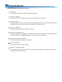
The following icons and symbols are used in the explanations in this manual.
Icon/Symbol
Description
This symbol indicates supplementary items to be aware of
when using the software.
This symbol indicates the location of a reference.
This symbol indicates content that should always be read.
This symbol indicates instructions that should always be
followed when using the software, or things to be careful of
when using the software.
This symbol indicates a space you to use for making notes.
"
[
This symbol is used to indicate the names of items on a
"
screen, references, dialog names, and connectors.
]
This symbol is used to indicate menu names, and sub-menu
names.
Using the Manual
This section explains the layout of the manual.
Introduction
The introduction explains the manual and safety precautions.
Chapter. 1 Overview
This chapter gives an overview of the system and an explanation of its features.
Chapter. 2 Setup
This chapter gives an overview of the components that make up the system. It also explains basic keypad
operation and a list of items that should be checked before using the system.
Chapter. 3 Recording
This chapter explains operations related to recording.
Chapter. 4 Connecting a PC
This chapter explains the procedure for connecting the system to a PC. Refer to the “Photron FASTCAM
Viewer User’s Manual” for additional details on using a PC to control the system.
Chapter. 5 Product Specifications
This chapter explains the system’s specifications.
Chapter. 6 Warranty
This chapter explains about the warranty.
Chapter. 7 Contacting Photron
This chapter lists the contact information to use when contacting Photron if the system malfunctions or if
a portion of the manual is unclear.
Using the System Safely and Correctly
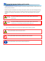
In order to prevent injury to yourself and others, and to prevent damage to property, carefully observe the
following safety precautions.
Photron has given its full attention to the safety of this system. However, the extent of damage and injury
potentially caused by ignoring the content of the safety precautions and using the system incorrectly is
explained next. Please pay careful attention to the content of the safety precautions when using the
system.
Warning
Caution
This symbol indicates actions that carry the risk that a person could receive a
serious injury.
This symbol indicates actions that carry the risk that a person could receive a
moderate injury, or that damage to physical property might occur.
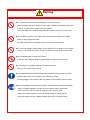
The safety precautions to be observed are explained with the following symbols.
This symbol indicates actions that require caution.
This symbol indicates actions that are prohibited and must be avoided.
This symbol indicates actions that must always be performed.
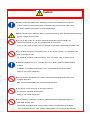
Warning
■ Do not perform actions that will damage the AC cable or plug.
(Do not damage the cable, modify it, use it near a heater, excessively bend, twist
or pull on it, place heavy objects on it, or bundle it.)
Using the cable when damaged can cause fire, electric shock, or a short circuit.
■ Do not use the system in a manner which will exceed the rating of the power
outlet or wiring equipment used.
Exceeding the power rating might cause a fire from excessive heat.
■ Do not insert metallic objects inside, or pour liquids such as water on, the system.
Doing so can cause fire, electric shock, or malfunction from short circuit or heat.
■ Do not disassemble or modify the system.
There are high voltages inside the system that can cause electric shock.
■ Do not plug in or unplug the power cord with wet hands.
Doing so can cause electric shock.
■ This chapter lists the contact information to use when contacting Photron if the
system malfunctions or if a portion of the manual is unclear.
Not fully plugging in the power cable can cause fire from electric shock or heat.
■ When something is wrong with the system, unplug the power cable immediately.
- When a foreign substance or liquid, such as metal or water, gets inside.
- When the outer case is broken or damaged, such as from a fall.
- When the system produces smoke, a strange smell, or strange sound.
Using the system in these conditions might cause a fire or electric shock.
Caution
■ Always unplug the system when cleaning it or when it is unused for a long period
of time. Leaving or storing the system connected to the power source might cause
fire from insulation deterioration or electrical discharge.
■Please consult to us in advance, When you perform shoot by which laser light and direct rays
go into a image sensor surface.
■ Do not set the system in a location where the temperature gets unusually hot.
The trunk and inside of a car can get especially hot in summer.
Doing so can cause the outer case and internal components to deteriorate or cause a fire.
■ Do not place the system in a location prone to oily smoke or steam, or in a location with
a lot of humidity or dust.
Oil, moisture, and dust conduct electricity, which can cause a fire or electric shock.
■ Ambient temperature 0-40° C, humidity 85% RH or lower, maximum altitude 2000m
or lower.
In addition, if exceeding these limits, use in a condensation-free environment.
Doing so can cause malfunction.
■ Do not store the equipment in a location where the temperature goes below -20°C
or higher than 60°C.
Also, prevent condensation from forming during shipment
■ This device is for indoor use, do not use it outdoors.
Do not use in a location that has dust.
Doing so can cause malfunction.
■ When shipping, remove the connecting cable and use the original packaging or a
dedicated carrying case.
Do not ship the equipment in an environment where the temperature goes below
-20°C or higher then 60°C. Also, prevent condensation from forming during shipment
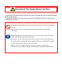
Cleaning of the Image Sensor Surface
Electrostatic Discharge (ESD) events may cause immediate and unrecoverable damage
to the image sensor.
Please read the following instructions and take EXTREME CARE when cleaning the
image sensor surface.
■ALWAYS take appropriate anti-static precautions when cleaning or working near the image
sensor.
■DO NOT use any form of cleaning equipment using electrostatic or ‘charged fiber’
technology.
■Please discharge any electrostatic build up in your body by touching a grounded metallic
surface before working near the camera sensor.
■Very gently , use only clean and dry air to remove dust from surface of the image sensor.
■To remove stubborn contamination use the highest grade (e.g. VLSI grade) pure isopropyl
alcohol (IPA) with optical wipes of ‘clean room’ grade.
■Extreme care must be taken! Gently wipe across the sensor in a single action.
(DO NOT rub to avoid abrasive damage to delicate optical coatings on the glass surface.)
Table of Contents
Chapter. 1
1.1.
Overview
1
Product Overview and Features ..............................................................................2
Chapter. 2
Setup
3
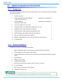
2.1.
System Components and Accessories ....................................................................4
2.1.1.
Components................................................................................................4
2.1.2.
Accessories/Options ...................................................................................4
2.2. Part Names ..............................................................................................................7
2.2.1.
Camera Controller.......................................................................................7
2.2.2.
Camera Controller Part Names...................................................................8
2.2.3.
Status Display LEDs on the front of the Camera Controller ....................... 9
2.2.4.
Camera Heads ..........................................................................................12
2.2.5.
High - G Housings.....................................................................................13
2.2.6.
Camera Cable (Selectable) ....................................................................15
2.2.7.
LCD Remote Controller (Optional)............................................................17
2.2.8.
RS-422 Serial Control ...............................................................................18
2.2.9.
I/O Cable ...................................................................................................19
2.2.10. Power Supply Connector ..........................................................................21
2.3. Device Connections ...............................................................................................22
2.3.1.
Connecting a Camera Head .....................................................................22
2.3.2.
Connecting the LCD Remote Controller (Optional) ..................................25
2.3.3.
Connecting a Video Monitor......................................................................25
2.3.4.
Connecting the AC Power Supply.............................................................26
2.3.5.
Connecting a PC .......................................................................................27
2.4. Memory Backup Battery ........................................................................................28
Chapter. 3
3.1.
3.2.
3.3.
3.4.
3.5.
3.6.
3.7.
3.8.
Recording
29
Selecting the Frame Rate ......................................................................................30
Selecting the Resolution ........................................................................................30
Selecting the Shutter Speed ..................................................................................31
3.3.1.
Changing SHUTTER LOCK......................................................................31
Selecting the Trigger Mode....................................................................................32
3.4.1.
START Mode.............................................................................................32
3.4.2.
CENTER Mode .........................................................................................32
3.4.3.
END Mode.................................................................................................33
3.4.4.
MANUAL Mode .........................................................................................33
3.4.5.
RANDOM Mode ........................................................................................33
LOW LIGHT Mode .................................................................................................34
White Balance Adjustment (Color Models Only)....................................................34
3.6.1.
Using Preset White Balance (Color Models Only) ....................................34
3.6.2.
Using User White Balance (Color Models Only).......................................34
Color Enhancement Function (Color Models Only) ...............................................35
Look-Up Table (LUT) Operations...........................................................................35
3.8.1.
Using Preset LUT Patterns .......................................................................35
3.8.2.
Using a Custom LUT.................................................................................38
3.9. Edge Enhancement Function ................................................................................38
3.10. Setting the Sensor Gain.........................................................................................38
3.11. Input/Output Signal Types......................................................................................39
3.11.1. TRIG TTL IN Connector ............................................................................39
3.11.2. TRIG TTL OUT Connector ........................................................................39
3.11.3. TRIG SW IN Connector ............................................................................39
3.11.4. SYNC IN Connector..................................................................................39
3.11.5. GENERAL IN Connector...........................................................................40
3.11.6. GENERAL OUT (1,2,3) Connector ...........................................................40
3.12. Using External Triggers..........................................................................................41
3.12.1. Inputting an External Trigger Signal..........................................................41
3.12.2. Outputting External Trigger Signals ..........................................................43
3.13. GENERAL Signal Settings.....................................................................................44
3.13.1. GENERAL IN Signal Settings ...................................................................44
3.13.2. GENERAL OUT Signal Settings ...............................................................45
3.14. Using External Synchronization Signals ................................................................46
3.14.1. Inputting an External Synchronization Signal ...........................................46
3.14.2. Outputting an External Synchronization Signal ........................................46
3.14.3. Synchronizing Multiple FASTCAM MC2.1 Systems (Multiple Unit
Synchronized Recording)..........................................................................47
3.14.4. Synchronizing the System with Other External Devices (Frame Rate
Synchronized Recording)..........................................................................50
3.14.5. Synchronizing the System with Other Cameras (Mixed Device
Synchronized Recording)..........................................................................52
3.15. Signal Delay...........................................................................................................53
3.16. Using Programmable Switch (USER SW) .............................................................54
3.17. Event Marker Function...........................................................................................55
Chapter. 4
4.1.
57
Connecting the Gigabit Ethernet Interface to a PC ...............................................58
4.1.1.
Connecting the System and a PC.............................................................59
4.1.2.
Setting the IP Address ..............................................................................59
4.1.3.
Using DHCP (Dynamic Host Configuration Protocol) ...............................59
4.1.4.
Connecting Multiple Systems and a PC ...................................................60
4.1.5.
Gigabit Ethernet Interface Initialization .....................................................60
Chapter. 5
5.1.
Connecting a PC
Product Specifications
61
Specifications .........................................................................................................62
5.1.1.
Product Specifications...............................................................................62
5.1.2.
General Specifications ..............................................................................63
5.1.3.
Options......................................................................................................64
5.1.4.
Frame Rate and Resolution ......................................................................64
5.1.5.
Recordable Image Count / Resolution......................................................64
5.1.6.
Shutter Speed List.....................................................................................65
5.2.
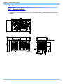
Dimensions ............................................................................................................66
5.2.1.
Camera Controller.....................................................................................66
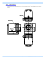
5.2.2.
Camera Head............................................................................................67
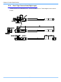
5.2.3.
Pencil Type Camera Head (Straight) ........................................................69
5.2.4.
Pencil Type Camera Head (Right angle) ..................................................70
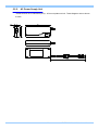
5.2.5.
AC Power Supply Unit ..............................................................................71
Chapter. 6
6.1.
73
About the Warranty ................................................................................................74
Chapter. 7
7.1.
Warranty
Contacting Photron
75
Contact Information................................................................................................76
Chapter. 1 Overview
1.1.Product Overview and Features
1
FASTCAM MH4-10K Hardware Manual
Chapter. 1 Overview
1.1.
Product Overview and Features
The FASTCAM MH4-10K is a camera that, by employing ultra-compact camera heads, makes it
possible to shoot in locations not previously accessible to conventional high speed camera heads.
As for the performance of the FASTCAM MH4-10K, it can record at a maximum resolution of 512 x
512 pixels at 2,000 fps (frames per second) at this full frame resolution, and up to a maximum speed
of 10,000 fps at reduced resolution. It is possible to record simultaneously with a maximum of four
camera heads attached to one controller case, even during high-G events, thanks to the high-G
design and construction of the camera heads and controller
Using real-time video output and an easy-to-use remote control, the camera can operate fully without
a PC connected. By connecting the camera controller to a PC via gigabit Ethernet, full camera
operations can be performed on the PC with the easy to use control software supplied.
Utilize the FASTCAM MH4-10K to view high-speed dynamic bodies slowed down with the latest
technology as an input system for video image processing. This manual explains the operating
procedures for the FASTCAM MH4-10K.
2
Chapter. 2 Setup
2.1. System Components and Accessories
2.2. Part Names
2.3. Device Connections
2.4. Memory Backup Battery
3
FASTCAM MH4-10K Hardware Manual
Chapter. 2 Setup
2.1.
System Components and Accessories
2.1.1.
Components
The system's standard components are listed below. Remove the components from the packaging
and check the system.
1.
Camera Controller
1
2.
Camera Head(s) (with tripod adapter)
Cube Type / Pencil Type
(depends on configuration)
3.
Camera Cable(s)
Cube Type / Pencil Type
(depends on configuration)
4.
AC Power Supply Unit / AC Cable
1
5.
Hexagonal Wrench for Flange Back Adjustment (1.5 mm)
1
6.
Gigabit Ethernet Interface Cable (LAN Cable)
1
7.
FASTCAM Series Setup Disk (Driver/Application CD)
1
8.
FASTCAM MH4-10K Hardware Manual (This Manual)
1
9.
Photron FASTCAM Viewer User's Manual
1
10. Making a Gigabit Ethernet Connection (Simple Procedure Manual)
1
11. IP address label
5
2.1.2.
Accessories/Options
The following options are available for the system.
1.
High-G Housings (High-G Lens Housing, Screw Reinforcement Housing)
2.
Tripod Adapter (For Cube type or Pencil type)
3.
Mounting Brackets (For the Camera Controller, Normal Camera head, High-G Camera
head)
4.
High-G Battery
5.
Cable Anchor Handle
6.
LCD Remote Controller
7.
NF Mount Lenses (Focal Lengths f=3.5mm, f=6mm, f=12 mm)
8.
C mount Adapter
9.
DC Connector for External Power Supply
10. Dedicated Carrying Case
The composition of a camera head turns into composition chosen at the time of purchase.
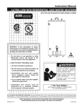
4
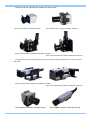
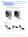
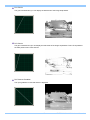
Examples with the optional parts installed are shown below.
High-G Lens Housing Installation Example
Screw Reinforcement Housing Installation Example
High-G Camera head Fixing Bracket Installation Example 1
High-G Camera head Fixing Bracket Installation Example 2
*(The high-g camera head fixing bracket and the normal camera head fixing bracket are the same except for
their width)
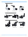
High-G Camera head Fixing Bracket Installation Example 1
High-G Camera head Fixing Bracket Installation Example 2
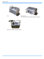
Tripod Adapter Installation Example (Cube)
5
Tripod Adapter Installation Example (Pencil)
FASTCAM MH4-10K Hardware Manual
Chapter. 2 Setup
Camera Controller Fixing Bracket Installation Example 1
Camera Controller Fixing Bracket Installation Example 2
Cable Anchor Handle Installation Example
6
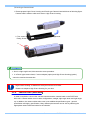
2.2.
Part Names
The system is composed of components including the Camera Controller, AC Power Supply Unit,
and the "Photron FASTCAM Viewer" controls software (referred to below as PFV).
For each of the system components.
- Do not use in an area with flammable gas or dust present.
- Do not place in an unstable location such as on a wobbly platform or an incline.
- Do not disassemble or modify.
- Do not expose to liquids such as water.
- Do not use in a manner where excessive force is applied.
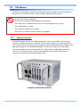
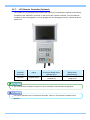
2.2.1.
Camera Controller
The FASTCAM MH4-10K has two models depended on memory size. Model 1 with a memory
capacity of 1 GB per camera unit, and model 2 with a memory capacity of 2 GB per camera unit.
They contain IC memory for saving images, and they have been designed with the capability to save
high-speed images as uncompressed digital data. The camera controller has a video output
connector to display live and recorded images on a video monitor, a Gigabit Ether interface to
connect a PC to fully control the cameras or download data, and various I/O (input/output)
connectors for external synchronization/trigger signals.
Camera Controller Exterior
7
FASTCAM MH4-10K Hardware Manual
Chapter. 2 Setup
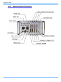
2.2.2.
Camera Controller Part Names
8
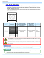
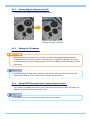
2.2.3.
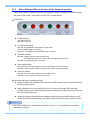
Status Display LEDs on the front of the Camera Controller
There are a number of LEDs on the front of the system's Camera Controller. These LEDs indicate
the status of the system. The meaning of each LED is explained here.
MAIN LEDs
POWER (Green)
LED ON: Power On
LED OFF: Power Off
IF LINK/TRANS (Red)
LED ON: The Gigabit Ethernet interface is connected
LED FLASHING: Data is transferring
LED OFF: The Gigabit Ethernet interface is not connected
TRIGGER (Yellow)
LED ON: A trigger signal is present (being input)
(The LED illuminates for 0.1 second when the trigger signal is input)
LED OFF: The trigger signal is not present
SYNC MODE (Red)
LED ON: External synchronization mode (synchronized to an external signal)
LED OFF: Internal synchronization mode (synchronized to the internal signal)
SYNC IN (Yellow)
LED ON: A synchronization signal is present (being input)
LED OFF: A synchronization signal is not present
Illumination/blinking in operational states
During low light mode operationLEDs other than POWER (Green) and IF LINK/TRANS (Red)
blink at a regular interval.
When calibration is run from USER SW or the LCD Remote Controller LEDs other than
POWER (Green) and IF LINK/TRANS (Red) blink alternately from right to left three times and
from left to right three times.
During the Gigabit Ethernet interface initialization LEDs other than POWER (Green) and IF
LINK/TRANS (Red) blink alternately from right to left and from left to right a number of times.
• For how to initialize of the Gigabit Ethernet interface, refer to "4.1.5. Gigabit Ethernet Interface
Initialization", page 60.
9
FASTCAM MH4-10K Hardware Manual
Chapter. 2 Setup
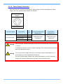
HEAD/MEMORY BOARD LEDs
CONNECT (Green)
LED ON: The Camera Controller is communicating with the Camera Head(s).
The LED does not illuminate by only connecting the camera cable
LED OFF: The Camera Controller is not communicating with the Camera Head
REC (Red)
LED ON: RANDOM mode ready state
LED FLASHING: Ready to record
LED OFF: Not recording
REC READY (Yellow)
LED ON: Ready to record
LED FLASHING: ENDLESS recording ("REC" LED also simultaneously flashes)
LED OFF: Not ready to record
10
BATTERY LED
CHARGE (Red)
LED ON: The battery is charging.
LED OFF: The battery is not charging.
FULL (Green) -> (Yellow) -> (Red) EMPTY
Indecates the remaining battery power.
Green
Yellow
Red
Remaining Battery
Remaining Battery
Remaining Battery
Power
Power
Power
100 - 90%
89 - 21%
20 – 0%
The battery’s condition is also indicated by the LED status.
LED ON: Running on external power.
LED FLASHING: Battery power memory protection.
11
FASTCAM MH4-10K Hardware Manual
Chapter. 2 Setup
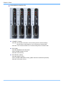
2.2.4.
Camera Heads
The FASTCAM MH4-10K’s camera head has been designed to be smaller than the previous models.
The camera head has been reduced to a revolutionary small size, while maintaining high
specifications such as a 512 x 512 resolution at recording rates up to 2000 fps.
This system can install two kinds of camera head type (“Cube Type” and “Pencil Type”)
Also each camera can choose a “Color Model” and “Monochrome Model”.
Multiple camera heads can also be connected to a single camera controller, and by operating the
cameras with a common synchronization signal, a single phenomenon can be simultaneously shot
from multiple angles.
* The maximum frame rate that can be set depends on the Camera Controller model.
Cube type head
Straight
Right angle
Cube type head
Straight
Right angle
Pencil type head
12
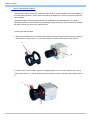
2.2.5. High - G Housings
In this section, we explain how to inatall the Hi-G housing to fit any type of camera head.
“Screw Reinforcement Housing” is enclosed by the product.(If you choose Cube type camera head)
1. Prepare the camera head screw reinforcement housing facing the direction shown in the photo.
2. Attach it to the camera, as shown below, and fasten it with the four screws provided as shown
below.
Camera head
Screw Reinforcement Housing
Screws
Screws
• When attaching a tripod adapter (option), it is necessary to remove Reinforcement Housing.
13
FASTCAM MH4-10K Hardware Manual
Chapter. 2 Setup
High-G Lens Housing (Option)
The basic lens mount for the FASTCAM MH4-10K is the NF mount, and NF lenses are available as
an optional price list them. The NF mount can also be changed to a C mount by using the optional C
mount adapter.
Specialized High-G housings (optional) are also available for the optional lenses. The High-G
capability of the lens can be enhanced by attaching the High-G housing. The procedure for installing
the High-G housing on the lens is explained next.
◇Cube type Camera Head
1. With the lens attached to the camera head, prepare the High-G lens housing facing the direction
shown below. Loosen screw “A” at this time and peel off the stickers used to cover part “B”.
A
B
2. Cover the lens with the high-g housing and lightly tighten screw “A”so the housing won’t move.
Then secure section “C” and its diagonal opposite with hex-screws, and finally, firmly tighten screw
“A”.
A
C
14
◇Pencil type Camera Head
1. Please prepare High-G lens Housing and Pensil type Camera Head with lens as following figure.
Camera head is made to slide and it sets to High-G lens Housing.
2. Two screws in the bottom of High-G lens Housing is tightened.
Finally, Screw “A” is tightened.
A
• Also in a light angle head, it becomes the same procedure.
• In a Pencil type camera head, C mount adapter (option) and High-G lens Housing (option)
cannot be used at the same time
“High-G lens Housing” is different for every kind of lens to be used.
Please use adaptive High-G lens Housing for your lens.
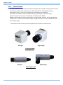
2.2.6.
Camera Cable (Selectable)
A cable is required to connect the camera controller and the camera head on the FASTCAM
MH4-10K. Camera cables come in three configurations, straight, right angle down and right-angle
up. In addition, the camera cables also come in two additional specification types: general
specification and high-g specification. Many different phenomena can be shot by selecting the
appropriate camera head and cable for the situation.
15
FASTCAM MH4-10K Hardware Manual
Chapter. 2 Setup
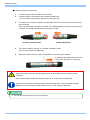
■ Photos of a general specification cable attached to a camera head (right-angle camera head
shown)
Straight
Right Angle Down
Right Angle Up
■ Photos of a high-g specification cable attached to a camera head (high-g housing attached,
right-angle camera head shown)
Straight
Right Angle Down
Right Angle Up
• A pencil type head differs in the connection method.
Please refer to “2.3.1”, Connecting a camera head, page 24.
When securing the camera cable, do not bend it R50 or lower.
Always secure the camera cable externally in one location within 60 cm of the connector.
16
2.2.7.
LCD Remote Controller (Optional)
The system can be operated while checking the monitor by connecting the optional LCD Remote
Controller to the "KEYPAD" connector on the front of the Camera Controller. The LCD Remote
Controller is also hot-pluggable, it can be plugged into and unplugged from the camera while the
power is on.
Camera
Controller
Connector
Signal
Camera Controller
Connector Model Name
(Manufacurer)
Keypad Connector
Model Name
(Manufacurer)
KEYPAD
Keypad signal
PT02A-12-10S (023)
(Amphenol)
PT06A-12-10P (023)
(Amphenol)
• The LCD Remote Controller is optional. It is not included in the standard configuration.
• For how to operate of the LCD Remote Controller, refer to "LCD Remote Controller User's
Manual".
17
FASTCAM MH4-10K Hardware Manual
Chapter. 2 Setup
2.2.8.
RS-422 Serial Control
The system supports serial control via an RS-422 connection through the “KEYPAD” connector.
By setting the STATUS OUT menu to ON, the system status can be output via the serial connection.
For details, check the command list.
A cable is not offered as an accessory. When using RS-422 control, construct a cable using the pin
diagram below as a reference.
Keypad Pin Diagram
PT02A-12-10S (023)
Connector
Name
KEYPAD
Signal Name
Pin
No.
+12V OUT
A
SIGNAL GND
B
RXD+
C
RXD-
D
TRIGGER SW
E
TXD-
F
TXD+
G
POWER GND
H
VBS GND
J
VBS
K
Camera Controller
Connector Model Name
(Manufacturer)
Cable Connector
Model Name
(Manufacturer)
PT02A-12-10S (023)
(Amphenol)
PT06A-12-10P (023)
(Amphenol)
Input
Connector
Not
Specified
When using the connector pins directly, refer to the chart above and ensure the wiring is correct.
Incorrect wiring can cause malfunction.
The voltage on pin A (+12V OUT) is used to power the LCD Remote Controller, do not use it for
other purposes.
• For inquires related to our product, refer to “7.1. Contact Information”, page 76.
• Serial control commands are available as separate list of commands. Please contact Photron or
the store where the system was purchased about the command list.
18
2.2.9.
I/O Cable
By inputting an external trigger or synchronization signal and by outputting an exposure timing or
synchronization signal, these signals can be used as a part of the FASTCAM MH4-10K system. The
input/output signal connectors on the camera controller have been bundled into a single connector,
the I/O connector, and it is possible to connect to access each type of signal by using the specialized
multi-connector.
A signal other than the specified signal must not be input to the various connectors.
Use extreme caution as there is a risk of damage to both devices, the input device and the
output device.
TRIG TTL IN
TRIG TTL OUT
TRIG SW IN
SYNC IN
GENERAL IN
GENERAL OUT1
GENERAL OUT2
GENERAL OUT3
I/O Pin DIagram
PT02A-16-26P (023)
• For signals that can be input, refer to “3.10. Input/Output Signal Types”.
19
FASTCAM MH4-10K Hardware Manual
Chapter. 2 Setup
Connector
Name
Signal Name
I/O PORT
TRIGGER TTL IN
TRIGGER TTL
OUT
TRIGGER SW
SYNC IN
GENERAL IN
GENERAL OUT1
GENERAL OUT2
N.C.
N.C.
N.C.
N.C.
N.C.
N.C.
N.C.
N.C.
POWER GND
GENERAL OUT3
SIGNAL GND
SIGNAL GND
N.C.
SIGNAL GND
+18 - +V36
+18 - +V36
+18 - +V36
N.C.
N.C.
Pin
Num.
A
Body-side Connector
Model Name(Maker)
Cable-side Connector
Model Name(Maker)
Input-side
Connector
BNC
B
BNC
C
D
E
F
G
H
J
K
L
M
N
P
R
S
T
U
V
W
X
Y
Z
a
b
c
BNC
BNC
BNC
BNC
BNC
BNC
BNC SHIELD
-
PT02A-16-26P(023)
(Amphenol)
• Pin U’s SIGNAL GND signal is the BNC ground.
20
PT06A-16-26S(424)
(Amphenol)
2.2.10. Power Supply Connector
This connector is the connector to input the DC power supply. Connect the supplied AC Power
Supply Unit or the optional external battery for operation.
DC 22-32V 65VA Pin
Diagram
PT02A-8-4P (023)
Connector Name
Signal Name
RESERVE
DC 22-32V 65VA
Warning
Pin
No.
Camera Controller
Connector Model Name
(Manufacurer)
Cable Connector
Model Name
(Manufacturer)
PT02A-8-4P (023)
(Amphenol)
PT06A-8-4S (424)
(Amphenol)
A
SIGNAL GND
B
POWER GND
+22V~+32V IN
C
D
When using the connector pins directly, refer to the chart above and ensure the wiring
is correct.
If the wiring is incorrect, not only is there the danger of the system malfunctioning, but
also of fire and electric shock.
Warning
Do not use a power supply which does not meet the system's specifications, or a
power supply you cannot guarantee the safety of.
By using a power supply outside of the system specifications, not only is there the
danger of the system malfunctioning, but also of fire and electric shock.
21
FASTCAM MH4-10K Hardware Manual
Chapter. 2 Setup
2.3.
Device Connections
2.3.1.
Connecting a Camera Head
Follow the procedure below to connect a Camera Head to the Camera Controller.
1.
Verify the Camera Controller's power is off.
2.
Connect the camera cable. Check the connector part of the Camera Head and Camera
Controller and connect them as shown in the pictures below.
■Camera Controller
Fix with a screw
General Cable
High-G Cable
■Camera head
◇For the Straight Camera head
Straight
Right-Angle Down
22
Right-Angle Up
◇For the Right-Angle Camera head
Straight
Right Angle-Down
Right Angle-Up
◇For the Straight Camera head with High-G Housing
Straight
Right-Angle Down
Right-Angle Up
◇For the Right-Angle Camera head with High-G Housing
Straight
Right-Angle Down
23
Right-Angle Up
FASTCAM MH4-10K Hardware Manual
Chapter. 2 Setup
■In case of the Pencil Type Head
1.
2.
It checks that the camera controller is turned off.
A camera cable is connected to the camera controller side.
* The connection method is the same as a cube type head.
3.
The cable from a camera controller and the cable which has come out of the camera head
are connected.
Each connector part is checked, as shown in the following figure a red point is united and it
connects. If it inserts normally, there is a feeling of a click.
■Camera Controller Side
■Camera Head Side
4.
The camera cable by the side of a camera controller is fixed.
(The screw for fixation is tightened.)
5.
When you remove camera cable, it is possible to remove to pull to outside.
It draws out in the direction of an arrow.
Press down the place of a red point.
Always secure the camera cable by tightening the screws attached to the camera cable's
connector.
If the camera cable is pulled out while the power is on, it can cause a malfunction.
Always turn the Camera Controller's power off when attaching or removing Camera Heads.
Adding or removing Camera Heads with the power on can cause a malfunction.
• You can also use connection of only one camera.
24
2.3.2.
Connecting the LCD Remote Controller (Optional)
If you have the optional LCD Remote Controller, connect it by plugging the LCD Remote Controller
connector into the connector labeled "KEYPAD" on the front of the Camera Controller.
• The LCD Remote Controller is hot-pluggable. It can be plugged in and removed while the
system's power is on.
• For how to operate of the LCD Remote Controller, refer to "LCD Remote Controller User's
Manual".
2.3.3.
Connecting a Video Monitor
A video monitor connected to the Camera Controller can be used to check the live image (camera
pass-through image). Connect the “VIDEO OUT” connector on the front of the Camera Controller to
the video input on the video monitor with a BNC cable.
Video Equipment (Monitor)
Video Equipment (VCR)
“VIDEO OUT” Connector
25
FASTCAM MH4-10K Hardware Manual
Chapter. 2 Setup
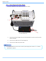
2.3.4.
Connecting the AC Power Supply
Connect the supplied AC Power Supply Unit to the power supply.
1.
AC Power Supply Unit
2.
1.
Connect the AC Power Supply Unit to the "DC22-32V 65VA" connector on the front of the
Camera Controller.
2.
Connect the AC cable to the AC Power Supply Unit.
3.
Connect the AC cable to the power outlet.
• For power supplies that can be used, see the DC power supply item in section “5.1.2. General
Specifications”, page 63.
26
2.3.5.
Connecting a PC
The system can have the operation of its functions performed from a PC using the Gigabit Ethernet
interface.
This section explains the required setup when connecting the system to a PC.
Gigabit Ether Connector
To connect a PC to the system, connect the system to a commercially available
1000BASE-T-compatible interface board with a LAN cable. For the LAN cable, prepare a UTP or
STP CAT5E (enhanced category 5) or higher LAN cable. (UTP: unshielded, STP: shielded)
The maximum cable length between the PC and the system is, compliant to the 1000BASE-T
specification, up to 100 m. One PC can connect to a maximum of 64 Photron Gigabit Ethernet
interface equipped cameras using a hub. When connecting multiple devices, connect through a
switching hub that can connect at 1000BASE-T. The maximum length of the cable that connects the
system (or PC) to the switching hub is also 100 m.
• For operating instructions of Photron FASTCAM Viewer software, refer to "Photron FASTCAM
Viewer User's Manual".
27
FASTCAM MH4-10K Hardware Manual
Chapter. 2 Setup
2.4.
Memory Backup Battery
A memory battery backup (referred to below as the battery) is built-in to the FASTCAM MH4-10K as
standard. If the external power supply becomes disconnected, the battery can retain the contents of
memory for a maximum of about 30 minutes. The battery is charged when the camera controller is
connected to an external power supply.
The status of the battery can also be checked by pressing the BATTERY CHECK button, even when
the power is off.
BATTERY CHECK BUTTON
The Memory Backup function is being interlocked with POWER SW of a controller.
When a POWER SW is turned OFF, the image data in a memory are not kept up.
The life time of a backup battery becomes about one year. However, it changes with
environment.
When you are pushed the BATTERY CHECK button in the state of “POWER OFF”, any LED for
a status check will be turned on.
If any LED for a status check does not light up at all, It means that a battery is in an empty state.
Or the life time of the backup battery may be exhausted.
For inquires related to replacement of backup battery, refer to "7.1. Contact Information", page
769.
28
Chapter. 3 Recording
3.1. Selecting the Frame Rate
3.2. Selecting the Resolution
3.3. Selecting the Shutter Speed
3.4. Selecting the Trigger Mode
3.5. LOW LIGHT Mode
3.6. White Balance Adjustment (Color Models Only)
3.7. Color Enhancement Function (Color Models Only)
3.8. Look-Up Table (LUT) Operations
3.9. Edge Enhancement Function
3.10. Setting the Sensor Gain
3.11. Input/Output Signal Types
0. Using External Triggers
3.13. GENERAL Signal Settings
3.14. Using External Synchronization Signals
3.15. Signal Delay
3.16. Using Programmable Switch (USER SW)
3.17. Event Marker Function
29
FASTCAM MH4-10K Hardware Manual
Chapter. 3 Recording
3.1.
Selecting the Frame Rate
With the system, you can record images from 60 (50 PAL) to 2,000 fps using the full 512x512 pixel
resolution of the image sensor. For frame rates higher than 2,000 fps, high-speed photography is
achieved by limiting the read area of the image sensor.
* The maximum frame rate that can be set depends on the Camera Controller model.
• The minimum frame rate in NTSC mode is 60 fps.
• The minimum frame rate in PAL mode is 50 fps.
• For frame rates over 2,000 fps, the resolution is automatically set to the maximum available at
that frame rate. For details, see "5.1.4. Frame Rate and Resolution", page 64.
3.2.
Selecting the Resolution
With the system, you can record images with a maximum size of approximately 260,000 pixels using
the high-speed image sensor, which has a maximum size of 512x512 pixels. You can also record at
even faster frame rates or reduce the amount of image data to make even longer recordings by
limiting the resolution according to the application.
• For more information of relation between Frame Rate and Resolution, refer to "5.1.4. Frame Rate
and Resolution", page 64.
30
3.3.
Selecting the Shutter Speed
With the system, the shutter speed is independent of the frame rate, and you can control the
exposure timing one frame using the electric shutter. By making an exposure that is of a shorter
period than the frame rate, high-speed objects can be recorded blur-free.
Shutter speed can be set from 1/frame sec to a maximum of 1/160,000 s (approximately 6.2 us).
The procedure for selecting the shutter speed is explained here.
• For more information of shutter speed, refer to “5.1.6. Shutter Speed List”, page 65.
3.3.1.
Changing SHUTTER LOCK
By switching between [ON] and [OFF] on the [SHUTTER LOCK] submenu on the [SHUTTER] menu,
the shutter speed value first used when the frame rate is changed can be set.
ON: Changing the frame rate does not change the shutter speed, it maintains the current setting.
OFF: Changing the frame rate automatically sets the shutter speed to 1/frame s.
31
FASTCAM MH4-10K Hardware Manual
Chapter. 3 Recording
3.4.
Selecting the Trigger Mode
With the system, in order to reliably capture high-speed phenomena, many kinds of trigger modes
have been made available. These trigger modes are explained next.
There are five types of trigger modes which are listed below.
- START
3.4.1.
- CENTER
- END
- MANUAL
- RANDOM
START Mode
START mode is a trigger mode where recording starts the instant the trigger is input, the scene is
recorded until the memory is full, and then recording ends. This mode is suitable for taking images of
high-speed phenomena when what will happen, and when it happens, is known in advance.
For example, in a situation with a maximum useable memory of two seconds of recording, two
seconds of high-speed video is saved immediately after the trigger is input.
3.4.2.
CENTER Mode
CENTER mode is a trigger mode where an equal amount of content recorded before and after the
trigger is input is saved to memory. This mode is suitable for viewing before and after an important
instant. For example, in a situation with a maximum useable memory for two seconds of recording,
one second before and one second after the trigger was input is recorded for a total of two seconds
of high-speed video.
32
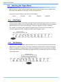
3.4.3.
END Mode
END mode is a trigger mode where the content recorded immediately before the trigger is input is
saved to memory. This mode is suitable for recording a high-speed phenomenon where it is hard to
predict when the important action will start and stop. For example, in a situation with a maximum
useable memory for two seconds of recording, the two seconds of high-speed video immediately
before when the trigger was input are saved.
3.4.4.
MANUAL Mode
MANUAL mode is a trigger mode, similar to CENTER mode, where the content recorded before and
after the trigger is input is saved to memory, but the proportion of time before and after the trigger
can be set as required. For example, in a situation with a maximum record time of two seconds, 0.5
seconds before and 1.5 seconds after the trigger is input are recorded and saved, a total of two
seconds of high-speed video.
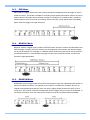
3.4.5.
RANDOM Mode
RANDOM mode is a trigger mode where each time a trigger is input only a predetermined number of
frames are saved to memory. For example, this function is convenient for a subject which is an
irregular and repeated phenomenon which can have a trigger output produced for each cycle or
occurrence. The number of frames recorded each time the trigger is input can be set as desired, in
one frame increments, from one frame to the maximum of all the recordable frames available.
33
FASTCAM MH4-10K Hardware Manual
Chapter. 3 Recording
3.5.
LOW LIGHT Mode
The more you increase the frame rate or shutter speed of a high-speed camera, the more the amount
of light entering the camera decreases, making the displayed image dark. Low light mode is a
function that temporarily increases the exposure time, making the displayed image easier to see for
setting the lens focus or other options.
3.6.
White Balance Adjustment (Color Models Only)
On digital video cameras, photographing white as pure white is described as "having the appropriate
white balance." On the system's color models as well, in order to take images with the correct color
representation, the white balance must be adjusted for the color temperature of the light source used.
The intensity of each color, R, G, and B, can be adjusted on this system. By adjusting the balance of
those three colors to match the light source used, the appropriate white balance can be achieved.
Two methods are available for adjusting the white balance, preset and user-editable white balance.
These methods are explained in this section.
3.6.1.
Using Preset White Balance (Color Models Only)
With the system, there are two types of white balance presets (5100K, 3100K) for use with common
light sources. The suggested color temperature for these presets is listed below.
5100K (Daylight, Outdoors)
3100K (Halogen Light Source)
3.6.2.
Using User White Balance (Color Models Only)
Each Camera Head can be assigned a user white balance setting in order to achieve the most
appropriate white balance for the light source used and the conditions during recording.
The values set here are stored for each camera head in the Camera Controller's internal memory as
a user preset, and the values can be loaded by selecting USER.
34
3.7.
Color Enhancement Function (Color Models Only)
Color models feature a color enhancement setting. The image color enhancement level can be
adjusted in five steps, including the OFF setting. The content of each item is listed in the chart below.
Menu Display
Contents
OFF
x0.5
(LEVEL1)
Sets x0.5 color enhancement
x1
(LEVEL2)
Sets x1 (default) color enhancement
x1.5
(LEVEL3)
Sets x1.5 color enhancement
x2
(LEVEL4)
Sets x2 color enhancement
3.8.
Turns the color enhancement mode off
Look-Up Table (LUT) Operations
The LUT (Look-Up Table) refers to a reference table that defines the relationship between the pixel
brightness gradation of the original image data taken and the brightness gradation displayed on a
computer screen or video monitor.
The system contains a hardware LUT function, and you can display the image data taken with
improved contrast (light and dark sharpness) or make an object in the image stand out by
emphasizing a specified gray level range.
• When an image is saved with its brightness converted with the LUT, the image saved is the image
that has had its brightness converted.
3.8.1.
Using Preset LUT Patterns
Six preset LUT patterns have been prepared in advance on the system. Each of these patterns is
explained in sequence in this section.
35
FASTCAM MH4-10K Hardware Manual
Chapter. 3 Recording
D1: Gain 1x
The input is always linear output. This LUT is used for normal conditions.
D2: Gamma 0.6
This LUT is 0.6 gamma correction.
D3: Gamma 0.45
This LUT is 0.45 gamma correction.
36
D4: Gain 2x
The gain is doubled and you can display the dark areas of the image emphasized.
D5: Gain 4x
The gain is doubled and you can display the dark areas of the image emphasized. This LUT emphasizes
the dark portions even more than D4.
D6: Reverse Gradation
The input gradation is reversed and then displayed.
37
FASTCAM MH4-10K Hardware Manual
Chapter. 3 Recording
3.8.2.
Using a Custom LUT
Creating a LUT pattern is done with PFV.
• For the creation method of a LUT pattern, refer to “Photron FASTCAM Viewer User's Manual”.
3.9.
Edge Enhancement Function
With the system's edge enhancement setting, you can enhance the edges in the recorded image in
three steps.
Menu Display
OFF
LEVEL1
Contents
Edge enhancement off.
Edge enhancement set to weak.
LEVEL 2
Edge enhancement set to medium.
LEVEL 3
Edge enhancement set to strong.
3.10. Setting the Sensor Gain
The sensor gain setting adjusts the amplitude voltage inside the sensor. By increasing this setting,
when recording in low light, the signal is amplified and the camera can take a higher gain (brighter)
image. However, by amplifying the signal, the noise component also increases, resulting in
decreased image quality, or more noise.
The sensor gain can be set in two steps according to the object being recorded. The content of each
item is listed in the chart below.
Menu Display
Contents
x1
Sets the sensor gain to standard.
x3
Sets the sensor gain to 3x.
38
3.11. Input/Output Signal Types
With the system, many signals can be input and output through the BNC connectors. Signals that
can be input and output from the BNC connectors are listed below.
A signal other than the specified signal must not be input to the various connectors.
Use extreme caution as there is a risk of damage to both devices, the input device and the
output device.
3.11.1. TRIG TTL IN Connector
The system recognizes an external TTL signal as a trigger during the READY or ENDLESS
recording state. Starting and stopping recording (in the selected recording mode) is controlled with
this signal.
Input voltage is 0V to +12V (H level +4.5V to +12V), positive or negative polarity, pulsewidth is 50 ns
or greater.
Operating current is 10 mA recommended, 30 mA maximum.
3.11.2. TRIG TTL OUT Connector
A 5V TTL trigger signal is output for input to an external device.
3.11.3. TRIG SW IN Connector
This trigger is input during the READY or ENDLESS recording state by contact between the BNC
connector's shield and a center pin (switch closure). The center pin normally has voltage flowing
through it. Use caution to avoiding contact with other pins.
3.11.4. SYNC IN Connector
The system recognizes a TTL signal from other devices as a synchronization signal.
Input voltage is 0V to +12V (H level +4.5V to +12V), positive or negative polarity, pulsewidth is 50 ns
or greater.
Operating current is 10 mA recommended, 30 mA maximum.
39
FASTCAM MH4-10K Hardware Manual
Chapter. 3 Recording
3.11.5. GENERAL IN Connector
The effect when a signal is input is described below, and can be optionally selected and set.
The input voltage is 0V to +12V (H level +4.5V to +12V), positive or negative polarity, pulsewidth is
50 ns or greater.
Operating current is 10 mA recommended, 30 mA maximum.
EVENT POS/NEG
TRIG POS/NEG
READY POS/NEG
Inputs an event signal (event marker).
Inputs a TTL trigger signal.
Inputs a change recording ready status signal (READY ON/OFF).
• To make the setting from the menu, refer to “3.13.1. GENERAL IN Signal Settings”, page 44.
• To make the setting from PFV, refer to "Photron FASTCAM Viewer User’s Manual".
3.11.6. GENERAL OUT (1,2,3) Connector
These are also BNC connectors. The signals below can be changed and output from the menu or
PFV.
SYNC POS/NEG
EXPOSE POS/NEG
REC POS/NEG
TRIG POS/NEG
READY POS/NEG
(POS: positive polarity, NEG: negative)
Outputs a vertical synchronization signal.
Outputs the camera's exposure period signal.
* Outputs during both LIVE and recording.
Outputs a signal during recording.
Outputs the trigger signal the camera received.
Outputs a signal that indicates the recording ready state.
• For details refer to “3.13.2. GENERAL OUT Signal Settings”, page 45.
40
3.12. Using External Triggers
With the system, you can record by receiving various trigger signals matched to the recording
application. The trigger signals that can be used with the system are explained here.
3.12.1. Inputting an External Trigger Signal
The external trigger signals that can be used with the system and their input system are listed below.
External trigger signal input settings are also made by selecting [SYNC IN/OUT] from the menu and
[TRIG TTL IN] or [GENERAL IN] from the submenu.
The signals input from the TRIG TTL IN and GENERAL IN connectors are explained in section
"2.2.9. I/O Cable".
Connector Name
(Input System)
Menu
TRIG POS
Isolated IC Input 0V - +12V (H level +4.5 - +12V),
Positive Polarity
TRIG NEG
Isolated IC Input 0V - +12V (H level +4.5 - +12V),
Negative Polarity
TRIG POS
Isolated IC Input 0V - +12V (H level +4.5 - +12V),
Positive Polarity
TRIG NEG
Isolated IC Input 0V - +12V (H level +4.5 - +12V),
Negative Polarity
TRIG TTL IN
GENERAL IN
TRIG SW IN
Signal
None
Contact signal
When a trigger signal is input to GENERAL IN, set the signal to be input from the menu in advance
before using it.
Use caution not to input more than specified voltage or current to the TRIG TTL IN and
GENERAL IN trigger signal inputs as there is a risk of damage to the equipment.
• For the setting method of the signal inputted into GENERAL IN, refer to “3.13.1. GENERAL IN
Signal Settings”, page 44.
41
FASTCAM MH4-10K Hardware Manual
Chapter. 3 Recording
TRIG TTL IN Circuit Diagram
+5V
IL611-3
IN1+ VDD
IN1- OUT1
IN2+ OUT2
IN2- GND
BLM18BA050SN1
TRIG_TTL_IN
390ΩF
TRIG_TTL
0.1μF
GND
SIGNAL_GND
TRIG SW IN Circuit Diagram
10KΩF
+5V
MICROSD150-02
NFW31SP506X1E4
TRIG_SW__IN
TRIG_SW
220ΩF
GND
0.1μF
GND
General IN / SYNC IN Circuit Diagram
+5V
IL611-3
390ΩF
SYNC
IN1+ VDD
IN1- OUT1
IN2+ OUT2
IN2- GND
SYNC_IN
GENERAL
BLM18BA050SN1
390ΩF
BLM18BA050SN1
GENERAL_IN
0.1μF
GND
SIGNAL_GND
42
3.12.2. Outputting External Trigger Signals
With the system, you can externally output trigger signals. Output is performed with the TRIG TTL
OUT connector's dedicated trigger output system provided by the system, and additionally, output
can also be optionally set from the GENERAL OUT connector. External trigger signal output settings
are also made by selecting [SYNC IN/OUT] from the menu and [TRIG TTL] OUT or [GENERAL
OUT] from the submenu.
Signal output is performed from the TRIG TTL OUT connector and the GENERAL OUT connector
explained in section “2.2.9. I/O Cable”.
The chart below summarizes the output systems and the signals that can be output.
Connector Name
(Output System)
Menu Setting
Reference Delay
Amount
Signal Type
TRIG POS
TTL, SW, SOFT, all TRIG pulse output
CMOS (74ACT541 buffer) output,
Positive Polarity.
TRIG NEG
TTL, SW, SOFT, all TRIG pulse output
CMOS (74ACT541 buffer) output,
Negative Polarity.
TRIG TTL OUT
TTL IN THRU
POS
TRIG TTL IN through output
CMOS (74ACT541 buffer) output,
Positive Polarity.
TTL IN THRU
NEG
TRIG TTL IN through output
CMOS (74ACT541 buffer) output,
Negative Polarity.
TRIG POS
TTL, SW, SOFT, all TRIG pulse output
CMOS (74ACT541 buffer) output,
Positive Polarity.
TRIG NEG
TTL, SW, SOFT, all TRIG pulse output
CMOS (74ACT541 buffer) output,
Negative Polarity
GENERAL OUT
43
For TRIG SW IN,
approx. 17.5 usec.
For TRIG TTL IN,
approx.
POS: 90n sec.
NEG:100n sec
For TRIG TTL IN,
approx. 45nsec.
For TRIG SW IN,
approx. 17.5usec.
For TRIG TTL IN
GENERAL IN,
approx.
POS: 90n sec.
NEG: 100n sec
FASTCAM MH4-10K Hardware Manual
Chapter. 3 Recording
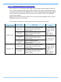
3.13. GENERAL Signal Settings
3.13.1. GENERAL IN Signal Settings
Details of the signals output from the GENERAL OUT connector explained in section “3.11.
Input/Output Signal Types” are shown in the chart below.
Menu Display
Contents
Signal
(Input Signal Conditions)
EVENT POS
Inputs a positive polarity event signal.
Isolated IC Input 0V - +12V
(H level +4.5 - +12V),
Positive Polarity
EVENT NEG
Inputs a negative polarity event signal.
Isolated IC Input 0V - +12V
(H level +4.5 - +12V),
Negative Polarity
TRIG POS
Inputs a positive polarity trigger signal.
Isolated IC Input 0V - +12V
(H level +4.5 - +12V),
Positive Polarity
TRIG NEG
Inputs a negative polarity trigger signal.
Isolated IC Input 0V - +12V
(H level +4.5 - +12V),
Negative Polarity
READY POS
READY NEG
Inputs a positive polarity READY signal.
READY ON/OFF is switched by a pulse input.
Inputs a negative polarity READY signal.
READY ON/OFF is switched by a pulse input.
Isolated IC Input 0V - +12V
(H level +4.5 - +12V),
Positive Polarity
Isolated IC Input 0V - +12V
(H level +4.5 - +12V),
Negative Polarity
Isolated IC Input 0V - +12V
(H level +4.5 - +12V),
Positive Polarity
Isolated IC Input 0V - +12V
(H level +4.5 - +12V),
Negative Polarity
When using the camera as a part of a system, verify the characteristics of the input signals
before using them.
• For the details of an EVENT POS/NEG setup, refer to “3.17.Event Marker Function”, page 55.
44
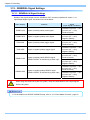
3.13.2. GENERAL OUT Signal Settings
Details of the signals output from the GENERAL OUT connector explained in section “3.11.
Input/Output Signal Types” are shown in the chart below. There are three GENERAL OUT
connectors and individual settings can be made for each connector.
Menu Display
Contents
Signal Type
SYNC POS
Outputs a positive polarity vertical synchronization
signal.
+5V CMOS output,
Positive Polarity
SYNC NEG
Outputs a negative polarity vertical synchronization
signal.
+5V CMOS output,
Negative Polarity
EXPOSE POS
Outputs the sensor's exposure interval at H level.
+5V CMOS output,
Positive Polarity
EXPOSE NEG
Outputs the sensor's exposure interval at L level.
+5V CMOS output,
Negative Polarity
REC POS
Outputs an interval signal during recording at H level.
+5V CMOS output,
Positive Polarity
REC NEG
Outputs an interval signal during recording at L level.
+5V CMOS output
Negative Polarity
TRIG POS
Outputs the trigger signal received by the camera at H
level.
+5V CMOS output,
Positive Polarity
TRIG NEG
Outputs the trigger signal received by the camera at L
level.
+5V CMOS output,
Negative Polarity
READY POS
Outputs a signal at H level during the trigger wait state.
(READY in START mode.) Only valid during START,
CENTER, END, and MANUAL modes.
+5V CMOS output,
Positive Polarity
READY NEG
Outputs a signal at L level during the trigger wait state.
(ENDLESS recording state in CENTER, END, MANUAL)
Only valid during START, CENTER, END, and MANUAL
modes.
+5V CMOS output,
Negative Polarity
IRIG RESET POS
Outputs the camera's internal IRIG reset signal (1PPS)
at H level.
+5V CMOS output,
Positive Polarity
IRIG RESET NEG
Outputs the camera's internal IRIG reset signal (1PPS)
at H level.
+5V CMOS output,
Negative Polarity
When using as a part of a system, verify the characteristics of the output signals before using
them.
45
FASTCAM MH4-10K Hardware Manual
Chapter. 3 Recording
3.14. Using External Synchronization Signals
An external synchronization mode to synchronize the camera to an external signal is provided on the
system. By using an external synchronization signal, you can record synchronizing the timing of the
recording using multiple systems or synchronize recording with external measuring devices and
lighting. The procedure for using the external synchronization signal is explained below.
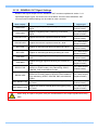
3.14.1. Inputting an External Synchronization Signal
With the system, you can input an external synchronization signal. The content of each item is listed
in the chart below.
Menu Display
Contents
Signal (Input Signal Conditions)
OFF
Sets external synchronization off,
operates independently.
(none)
ON CAM POS
Synchronizes to a positive polarity signal
from the system.
Isolated IC Input (+4.5V - +12V),
Positive Polarity
ON CAM NEG
Synchronizes to a negative polarity signal
from the system.
Isolated IC Input (+4.5V - +12V),
Negative Polarity
ON OTHERS POS
Synchronizes to a positive polarity signal
from an external device
(including other Photron products).
Isolated IC Input (+4.5V - +12V),
Positive Polarity
ON OTHERS NEG
Synchronizes to a negative polarity signal
from an external device
(including other Photron products).
Isolated IC Input (+4.5V - +12V),
Negative Polarity
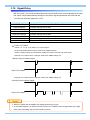
3.14.2. Outputting an External Synchronization Signal
With the system, you can externally output a synchronization signal. External synchronization
signals are output from the GENERAL OUT connector explained in section "Input/Output Signal
Types". The procedure for setting the output of an external synchronization signal is explained
below.
Menu Display
Contents
Signal Type
SYNC POS
Outputs a positive polarity
vertical synchronization signal.
CMOS (74ACT541 buffer)
Output, Positive Polarity
Approx. 100 ns
SYNC NEG
Outputs a negative polarity
vertical synchronization signal.
CMOS (74ACT541 buffer)
Output, Negative Polarity
Approx. 100 ns
46
I/O delay amuont
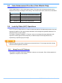
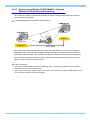
3.14.3. Synchronizing Multiple FASTCAM MC2.1 Systems
(Multiple Unit Synchronized Recording)
The system can perform synchronized recording by synchronizing multiple units using external
synchronization input/output.
Conceptual Diagram of a Synchronized Connection
CAMERA No.2
CAMERA No.1
(SLAVE)
SYNC IN
(MASTER)
SYNC OUT
(BNC Cable)
Synchronized recording settings using the system are made with the "LCD Remote Controller
(optional)" or PFV. The conceptual settings when performing synchronized recording using two
systems are explained here. First, decide which camera to make the master camera (outputs the
synchronization signal) and the slave camera (receives the synchronization signal) from the two
systems to use for synchronized recording.
Cable Connection
Connect the master camera controller's "GENERAL OUT" connector to the slave camera controller's
"SYNC IN" connector using a BNC cable.
When the synchronization signal is input to the "SYNC IN" connector, the SYNC IN LED (Yellow) on the
front of the slave camera controller illuminates.
47
FASTCAM MH4-10K Hardware Manual
Chapter. 3 Recording
Setting the Master Camera (Outputs Synchronization)
Set the signal output for the master camera which will output the synchronization signal. Synchronization
signal settings are made with the "LCD Remote Controller (optional)" or PFV.
For PFV (Standard)
1.
Verify that the camera mode is in LIVE mode (the image displayed is passed through from the
camera). If the system is in a mode other than LIVE mode, check "Live" on the camera
control panel.
2.
Select I/O on the left tree from "Camera Option" on the camera control panel.
3.
Set "GENERAL OUT1".
For the LCD Remote Controller (Optional)
1.
Verify that the camera mode is in LIVE mode.
2.
Press the LCD Remote Controller's MENU key and the menu list is displayed.
3.
Select GENERAL OUT1 from the SYNC IN/OUT submenu with the LCD Remote Controller's
ARROW keys and press the ENTER key.
4.
Select the signal to be output from the master Camera Controller's GENERAL OUT
connector from the menu. Move the cursor here to the SYNC POS item with the ↑↓ keys
and press the ENTER key to select.
5.
The master camera is set to output a positive polarity vertical synchronization signal from its
GENERAL OUT1 connector.
48
Setting the Slave Camera (Receives the Synchronization Signal)
Next, set the synchronization signal input for the slave camera which will receive the synchronization
signal supplied by the master camera. Synchronization signal settings are made with the "LCD Remote
Controller (optional)" or PFV.
For PFV (Standard)
1.
Verify that the camera mode is in LIVE mode (the image displayed is passed through from the
camera). If the system is in a mode other than LIVE mode, check "Live" on the camera
control panel.
2.
Select I/O on the left tree from "Camera Option" on the camera control panel.
3.
Set SYNC IN to "ON CAM POS".
For the LCD Remote Controller (Optional)
1.
Verify that the camera mode is in LIVE mode.
2.
Set the synchronization signal type that slave camera will receive. Press the LCD Remote
Controller's MENU key and the menu list is displayed.
3.
Select SYNC IN from the SYNC IN/OUT submenu with the LCD Remote Controller's
ARROW keys and press the ENTER key.
4.
The output previously set on the master Camera Controller has positive polarity (POSITIVE),
therefore it is necessary to make the setting on the slave Camera Controller the same,
positive polarity (POSITIVE). Move the cursor to the ON CAM POS item with the ↑↓ keys
and press the ENTER key to select.
• If steps 1-3 are completed when no synchronization signal is being input, the camera will not
operate normally. As detailed in the procedure, make the settings when the signal is being input.
49
FASTCAM MH4-10K Hardware Manual
Chapter. 3 Recording
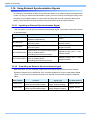
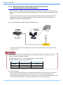
3.14.4. Synchronizing the System with Other External Devices
(Frame Rate Synchronized Recording)
With the system, in addition to the frame rate preset on the camera, a function has been provided
where you can receive a synchronization signal externally, set the frame rate to that frequency, and
record.
In this way, for example, the system can be synchronized with a dynamic body that spins at 450
revolutions per second to conduct high-speed recording at 450 fps. This can open up broad
applications that were unavailable until now.
Conceptual Diagram of External Synchronized Recording
450Hz
450fps
SLAVE
SYNC
Sync (Pulse)
Generator
SYNC IN
Frame rate synchronization signal settings on the system are made with the "LCD Remote Controller
(optional)" or PFV.
• When conducting frame rate synchronization recording with the system, the signal that can be
input must meet the following conditions.
■ Isolated IC Input (+4.5V - +12V), positive polarity or negative polarity
■ Frequencies are as shown in the table below
Model Name
Minimum Frequency
Maximum Frequency
model 500
60 Hz (50 Hz PAL)
500 Hz
model 2K
60 Hz (50 Hz PAL)
2,000 Hz
model 10K
60 Hz (50 Hz PAL)
10,000 Hz
Cable Connection
Input the synchronization signal from the device that generates the signal to the system. Connect the
synchronizing device's output signal to the system's “SYNC IN” connector using a BNC cable.
When the synchronization signal is input to the “SYNC IN” connector, the SYNC IN LED (Yellow) on the
front of the system illuminates. (* If the synchronization signal is lost, the LED goes out.)
50
System Settings
Frame rate synchronization signal settings on the system are made with the "LCD Remote Controller
(optional)" or PFV.
For PFV (Standard)
1.
Verify that the camera mode is in LIVE mode (the image displayed is passed through from the
camera). If the system is in a mode other than LIVE mode, check "Live" on the camera
control panel.
2.
Select I/O on the left tree from "Camera Option" on the camera control panel.
3.
Set ON OTHERS POS (positive polarity) or ON OTHERS NEG (negative polarity) according
to the polarity of the external synchronization signal.
For the LCD Remote Controller (Optional)
1.
Verify that the camera mode is in LIVE mode.
2.
Press the LCD Remote Controller's MENU key and the menu list displays.
3.
Select SYNC IN from the SYNC IN/OUT submenu with the LCD Remote Controller's
ARROW keys and press the ENTER key.
4.
Use the LCD Remote Controller's ↑↓ keys to select the input signal. Select ON OTHERS
POS (positive polarity) or ON OTHERS NEG (negative polarity) according to the polarity of
the external synchronization signal.
5.
When finished, press the ENTER key to complete the setting.
6.
Output the signal from the synchronization device and verify that the camera recognizes the
output frequency and synchronizes its frame rate. The recognized frame rate will display in
the lower left of the video monitor.
7.
Output the signal from the synchronization device and verify that the camera recognizes the
output frequency and synchronizes its frame rate. The recognized frame rate will display in
the lower left of the video monitor.
• The frequency of the synchronization signal cannot be changed during the LIVE or recording
state.(This is out of spec assurance.) The synchronization signal can be changed if you repeat
steps 1 through 6 after inputting the changed frequency. The system is reset.
• If no synchronization signal is input, or the input signal is under 60 Hz (50 Hz), during steps 1-6,
the display shows "NO SYNC INPUT".
• If steps 1 through 6 are made when inputting a signal that exceeds the frequency that can be
input, the display shows "OVER SYNC INPUT".
• The illumination of the LED on the front of the Camera Controller indicates that the
synchronization signal is being input. If the synchronization signal is lost, the LED goes out.
• A minute error occurs in the input synchronization signal due to the construction of the internal
circuitry of this function. For this system, an error of ±1 Hz can occur.
For example, when performing external device synchronization inputting a synchronization signal
of 10,000 Hz, the error is: 10,000 Hz ± 1 Hz = 9,999 fps to 10,001 fps.
51
FASTCAM MH4-10K Hardware Manual
Chapter. 3 Recording
3.14.5. Synchronizing the System with Other Cameras
(Mixed Device Synchronized Recording)
Using the function (frame rate synchronized recording) in the previous section, "3.13.4.
Synchronizing the System with Other External Devices", mixed-type synchronized recording can be
performed with Photron's other high-speed cameras (except for some older products).
In particular, the FASTCAM series high speed camera systems are also compatible with collective
control by the PFV control software.
CAMERA No.2
CAMERA No.1
(SLAVE)
SYNC IN
(MASTER)
SYNC OUT
(BNC Cable)
Basic Process
1.
Decide the master camera (the source of the synchronization signal) and the slave camera
(the camera that will operate according to the synchronization signal from the master).
Basically, by making the master camera the camera with the lowest maximum frame rate that
can be set, you can avoid setting a synchronization signal speed the slave camera cannot
receive.
2.
Connect the master camera's V-SYNC output connector to the slave camera's V-SYNC input
connector with a BNC cable, select the synchronization signal output polarity on the master
camera, and then set the slave camera to be operated by that signal.
For camera models that can perform synchronized recording or for detailed instructions on making the
settings, contact Photron at the contact information in "7.1. Contact Information"
• For camera models that can perform synchronized recording or for detailed instructions on
making the settings, contact Photron at the contact information in "7.1. Contact Information"
52
3.15. Signal Delay
With the system, you can set the signal delay time or pulse width for the various signals that are input
and output. Pulse width and delay settings for the various signals input/output are made with the
"LCD Remote Controller (optional)" or PFV.
Setting Item
TRIG TTL IN DELAY
SYNC IN DELAY
Setting Range (Value)
0-60 (s) 100 ns units
0-1/frame rate (s) 100 ns units
GENERAL IN DELAY
0-60 (s) 100 ns units
TRIG OUT WIDTH
0-1 (ms) 100 ns units
SYNC OUT DELAY
0-1/frame rate (s) 100 ns units
SYNC OUT WIDTH
0-500 (us), 1/frame rate (s) at 2,000 fps or higher 100 ns units
EXPOSE OUT DELAY
SYNC OUT TIMES
0-1/frame rate (s) 100 ns units
0.5, 1, 2, 4, 6, 8, 10, 20, 30 (* x1 is standard output)
SYNC OUT TIMES
Values 1, 2, 4, 6, 8, 10. A value of 1 is normal output.
Set from the SYNC IN/OUT menu, SYNC OUT TIMES submenu.
Output a SYNC (vertical synchronization signal) from SYNC OUT that is X times SYNC.
Example: For a frame rate of 1,000 fps, SYNC OUT TIMES setting of 2.
1,000 fps Synchronization Signal
SYNC OUT Output
Example: For a frame rate of 1,000 fps, SYNC OUT TIMES setting of 4.
1,000 fps Synchronization Signal
SYNC OUT Output
• When it is larger than 50,000fps, the setting becomes six or less.
• An accurate frequency is output, but when SYNC OUT TIMES is set to a large value with a high
frame rate, the setting may result in frequency errors.
53
FASTCAM MH4-10K Hardware Manual
Chapter. 3 Recording
3.16. Using Programmable Switch (USER SW)
There are four switches that can be set on the front of the system. Settings for the switches are made
from the menu and they can each be assigned a different function. The content of each setting is
listed in the chart below.
As an example, setting the USER1 switch on the front of the Camera Controller is explained here.
PFV
Setting
Explanation
OFF
Does not assign a function.
Change Frame Rate
Raises the frame rate.
Change Resolution
Lowers the resolution.
Change Shutter Speed
Increases the shutter speed.
Change Trigger Mode
Changes the trigger mode.
Fitting image
Adjusts the size of the image displayed on the video output to be the
maximum for the current resolution.
Status Display
Displays the status of camera settings on the video output.
Switch LIVE/MEMORY
Switches between LIVE and MEMORY states.
Record Ready
Sets the record ready state.
Record
Starts recording.
Low-Light
Turns low-light mode ON/OFF.
Head Select
It is changed the camera head to display at video out put
LCD Remote Controller (Optional)
Setting
Explanation
OFF
Does not assign a function.
FRAMERATE SEL
Raises the frame rate.
FRESOLUTION SEL
Lowers the resolution.
SHUTTER SEL
Increases the shutter speed.
TRIGGER SEL
Changes the trigger mode.
FIT
The same function as the [FIT] key on the LCD Remote Controller.
STATUS
The same function as the [STATUS] key on the LCD Remote Controller.
LIVE
The same function as the [LIVE] key on the LCD Remote Controller.
REC READY
The same function as the [REC READY] key on the LCD Remote
Controller.
REC
The same function as the [REC] key on the LCD Remote Controller.
LOW LIGHT
The same function as the [LOW LIGHT] key on the LCD Remote
Controller.
HEAD SELECT
It is changed the camera head to display at video out put
54
3.17. Event Marker Function
With the system, it is possible to input an external signal during recording, at the instant the frame
number is stored, and during playback you can immediately access, or jump to, the stored frame
numbers (event markers). This a separate feature from the trigger point, by marking interesting
points during recording, these points can be easily called up for review during playback. The event
marker can store ten positions within a sequence.
The frame number recording occurs on the pulse's edge, and the next frame after the pulse's edge is
input is stored as the event marker. Event marker settings can be made with the "LCD remote
controller (optional)" or PFV.
55
FASTCAM MH4-10K Hardware Manual
Chapter. 3 Recording
56
Chapter. 4 Connecting a PC
4.1. Connecting the Gigabit Ethernet Interface to a PC
57
FASTCAM MH4-10K Hardware Manual
Chapter. 4 Connecting a PC
4.1.
Connecting the Gigabit Ethernet Interface to a PC
The system can have the operation of its functions performed from a PC using the Gigabit Ethernet
interface.This section explains the required setup when connecting the system to a PC.
• For operating instructions of Photron FASTCAM Viewer software, refer to "Photron FASTCAM
Viewer User's Manual".
To connect a PC to the system, connect the system to a commercially available
1000BASE-T-compatible interface board with a LAN cable. For the LAN cable, prepare a UTP or
STP Cat 5e (enhanced category 5) or higher LAN cable. (UTP: unshielded, STP: shielded)
The maximum cable length between the PC and the system is, compliant to the 1000BASE-T
specification, up to 100 m. One PC can connect to a maximum of 64 Photron Gigabit Ethernet
interface equipped cameras using a hub. When connecting multiple devices, connect through a
switching hub that can connect at 1000BASE-T. The maximum length of the cable that connects the
system (or PC) to the switching hub is also 100 m.
Settings
■On the System
- IP Address Setting
■On the PC
- IP Address Setting
- Packet Size
- Time Out Length
- Communications Port
• The system is only 1000BASE-T compatible. When using a PC compatible with only 10BASE-T
or 100BASE-TX, the PC must be connected through a 10BASE-T, 100BASE-TX, and
1000BASE-T compatible switching hub.
• The system's factory default IP address is below:
IP ADDRESS > 192.168.0.10
NETMASK > 255.255.255.0
GATEWAY ADDRESS > 0.0.0.0
PORT > 2000 (Fixed, not changeable)
• Photron recommends using an STP cable over long distances or in noisy locations.
• For the setting method of IP address for camera system, refer to “4.1.2. Setting the IP Address”,
page 59.
• For the setting method of control PC, refer to “Photron FASTCAM Viewer User's Manual”.
58
4.1.1.
Connecting the System and a PC
Connect the LAN cable to the system as shown below.
Insert the LAN cable into the
"GIGABIT ETHER" connector.
4.1.2.
Setting the IP Address
• When connecting the system to a PC or when connecting other Gigabit Ethernet interface
compatible Photron cameras, set each of those devices to a different IP address. Also, when
connecting the system to an existing network, do not use IP addresses that are already in use on
the network.
• For the procedure for setting the IP address of the system, refer to the "Photron FASTCAM
Viewer User's Manual" or the "LCD Remote Controller User's Manual".
4.1.3.
Using DHCP (Dynamic Host Configuration Protocol)
The system is compatible with DHCP. In an environment where DHCP is used, the system's IP
address can be acquired from the DHCP server.
• For details, refer to the “Photron FASTCAM Viewer User’s Manual”.
59
FASTCAM MH4-10K Hardware Manual
Chapter. 4 Connecting a PC
4.1.4.
Connecting Multiple Systems and a PC
With PFV, the system’s control software, one PC can connect to and control multiple FASTCAM SA
series and MH4-10K high speed camera (Gigabit Ethernet) systems.
• When connecting to multiple systems, set the IP address of each one to a unique setting.
4.1.5.
Gigabit Ethernet Interface Initialization
When you cannot communicate well with the camera even though you are running PFV, the
system's control software, you may be able to improve the situation by performing the procedure
below.
1.
Of the four USER SW (Programmable Switches) on the front of the Camera Controller, press
and hold USER1 and USER4 for 10 seconds or more.
2.
The LEDs on the front of the Camera Controller will illuminate back and forth from left to right
and from right to left and inform you that the initialization of the Gigabit Ethernet interface has
completed normally.
60
Chapter. 5 Product Specifications
5.1. Specifications
5.2. Dimensions
61
FASTCAM MH4-10K Hardware Manual
Chapter. 5 Product Specifications
5.1.
Specifications
5.1.1.
Product Specifications
Image Sensor
CMOS image sensor
Sensor Resolution
512 x 512 pixels
Frame Rate
Lens Mount
2,000 fps full frame
NF mount , C mount (With adapter)
Monochrome
8bit
Recording Color Depth
Shutter
RGB, each 8-bit (Bayer color filter method)
Color
Electronic shutter
Recording Method
IC memory
Recording Memory Amount
1GB standard , 2GB maximum
Trigger Method
START, CENTER, END, MANUAL, RANDOM
Hardware LUT on camera, controllable via LCD Remote Controller
(optional) or software
Gain Control
Image Output Customization
External Synchronization
Input Signal
External Synchronization
Output Signal
Trigger Input Signal
Customizable LUT, brightness is changeable
Other Output Signals
5 Vp-p, negative polarity / positive polarity (switchable)
External Control
LCD Remote Controller (optional), RS-422 external control I/F,
digital IF (PC)
Video Output Signal
RS170 (NTSC),PAL, digital zoom function, with scroll, fit functions
Digital Interface
Gigabit Ethernet (1000BASE-T)
Isolated IC Input (+4.5V - +12V), negative polarity / positive polarity
(switchable)
5 Vp-p, negative polarity / positive polarity (switchable)
Isolated IC Input (+4.5V - +12V), contact
62
5.1.2.
General Specifications
Environment Conditions
Strage Temperature
-20℃ ~ 60℃ (No Condensation)
Strage Humidity
85% or less (No Condensation)
Guaranteed Operating
Temperature
0℃ ~40℃ (No Condensation)
Guaranteed Operating Humidity
85% or less (No Condensation)
Shock Resistance
Performance
100G 10ms 6axis (Guaranteed only when the lens is used a
reinforced NF mount lens)
Dimensions
Camera Controller
245 (W) x 160 (H) x 150 (D) mm
9.65” (W) x 6.3” (H) x 5.9” (D)
Cube type Head
35 (W) x 35 (H) x 34 (D) mm
1.38” (W) x 1.38” (H) x 1.34” (D)
Pencil type Head(Straight)
23 (W) x 22 (H) x 75 (D) mm
0.90” (W) x 0.86” (H) x 2.95” (D)
Pencil type Head(Right angle)
23 (W) x 23 (H) x 77 (D) mm
0.90” (W) x 0.90” (H) x 3.03” (D)
AC Power Suppy Unit
68 (W) x 35 (H) x 153 (D) mm, excluding protruding
2.66” (W) x1.36” (H) x5.98” (D)
AC Power Supply
Power Supply Voltage
Power Supply FVoltage
Japan 100V, US 120V, EU 240V
50Hz ~ 60Hz
Power Consumption
68VA
DC Power Supply
Power Supply Voltage
22V ~ 32V
Power Consumption
65VA
Weight
Camera Controller
7.6kg 16.8lb
Cube type Head
Pencil type Head
(Include Cable)
Straight
Right angle
AC Power Suppy Unit
90g
3.17 Oz
145g
5.10 Oz
140g
4.93 Oz
670g
46.2 Oz
Photron has verified two types of AC cables, type A (standard for Japan, USA, Canada, etc.)
and type SE (standard for Germany, France, etc.). However, when those cables cannot properly
receive power when plugged in, use the proper AC cable for the region's standards and verify
that AC cable works properly.
For inquires regarding the recommended AC cable for each region, contact that region's
Photron branch office or the distributor.
63
FASTCAM MH4-10K Hardware Manual
Chapter. 5 Product Specifications
5.1.3.
Options
User Option
High-G Housings (Lens, Camera head screw reinforcement Housing)
Tripod Adapter (for Cube type or Pencil type)
Mounting Brackets (For the camera controller, normal and high-g camera heads)
High-G Battery
Cable Anchor Handle
LCD Remote Controller
NF Mount Lenses (f=3.5mm , f=6mm , f=12mm)
C Mount Adapter
DC Connector for External Power Supply
Dedicated Carrying Case
5.1.4. Frame Rate and Resolution
Settable Resolution
Maximum
Frame Rate
Resolution
(fps)
512×512
512×352
512×256
512×128
512×96
50 (PAL)
○
○
○
○
○
60
○
○
○
○
○
125
○
○
○
○
○
250
○
○
○
○
○
500
○
○
○
○
○
1,000
○
○
○
○
○
2,000
○
○
○
○
○
512×352
3,000
×
○
○
○
○
512×256
4,000
×
×
○
○
○
5,000
×
×
×
○
○
6,000
×
×
×
○
○
7,000
×
×
×
○
○
512×512
512×128
512×96
8,000
×
×
×
○
○
9,000
×
×
×
×
○
10,000
×
×
×
×
○
5.1.5. Recordable Image Count / Resolution
Resolution
Recordable image count with
1 GB of memory
Recordable image count with
2 GB of memory
512×512
4,092
8,188
512×352
5,952
11,909
512×256
8,184
16,376
512×128
16,368
32,752
512×96
21,824
43,669
* Recording Time = Recordable Image Count x 1/frame rate (fps)
64
5.1.6. Shutter Speed List
1/frame
1/125
1/250
1/500
1/700
1/1,000
1/1,250
1/1,600
1/2,000
1/2,500
1/2,800
1/4,000
1/5,000
1/5,600
1/6,400
1/8,000
1/10,000
1/14,000
1/16,000
1/20,000
1/28,000
1/40,000
1/56,000
1/70,000
1/80,000
1/112,000
1/140,000
1/160,000
65
FASTCAM MH4-10K Hardware Manual
Chapter. 5 Product Specifications
5.2.
5.2.1.
Dimensions
Camera Controller
* All dimensions are in millimeters (mm) – 25.4 mm equals one inch. These diagrams are not shown
to scale.
1.3
150
245
8-M8 depth12max
126.3
196.13
180
160
BOTH SIDE
26.3
76.3
1.3
1.3
26.3
76.3
126.3
66
5.2.2.
Camera Head
* All dimensions are in millimeters (mm) – 25.4 mm equals one inch. These diagrams are not shown
to scale.
9.33
4*2*M3 DEPTH3
FRANGE BACK ADJUST SCREW
17.5
5
17.5
30
35
25
9.33
35
39.83
45.01
φ34
9.33
25
67
FASTCAM MH4-10K Hardware Manual
Chapter. 5 Product Specifications
With Tripod Adapter Attached
* All dimensions are in millimeters (mm) – 25.4 mm equals one inch. These diagrams are not shown to
scale.
FRANGE BACK ADJUST SCREW
8.5
26
42.3
39.83
16.33
6.33
26.33
1/4-20UNC
68
5.2.3.
Pencil Type Camera Head (Straight)
* All dimensions are in millimeters (mm) – 25.4 mm equals one inch. These diagrams are not shown
to scale.
11
2-M2 Depth 2
7
5
6
11
2-
φ
3.
29.8
2-M2 Depth 2
Pi
er
ce
24.2
M3 Depth 5
7
77.1
450
11
2-M2 Depth 2
23
7
35.8
36
48
φ15
2-M2 Depth 2
11
23.2
7
M3 Depth 5
69
FASTCAM MH4-10K Hardware Manual
Chapter. 5 Product Specifications
5.2.4.
Pencil Type Camera Head (Right angle)
* All dimensions are in millimeters (mm) – 25.4 mm equals one inch. These diagrams are not shown
to scale.
6
9.5
14.5
φ
3.
5
28.1
Pi
er
c
e
24.2
6
11
φ 3. 2
2-M2 Depth 2
M3 Depth 5
Pie rc
e
75.1
450
11.5
2-M2 Depth 2
6
23
11
21.6
14.6
11
36
M3 Depth 5
48
φ15
6
14.5
2-M2 Depth 2
70
5.2.5.
AC Power Supply Unit
* All dimensions are in millimeters (mm) – 25.4 mm equals one inch. These diagrams are not shown
to scale.
35
153
68
0.8
1500
71
FASTCAM MH4-10K Hardware Manual
Chapter. 5 Product Specifications
72
Chapter. 6 Warranty
6.1. About the Warranty
73
FASTCAM MH4-10K Hardware Manual
Chapter. 6 Warranty
6.1.
About the Warranty
This system has been shipped having undergone rigorous testing. However, in the unlikely event that
it malfunctions due to a manufacturing defect, it will be repaired, at no charge, within the warranty
period.
Warranty Exceptions
The following exceptions will result in fee-based repair, even within the warranty period.
1.
Damage or malfunction as a result of fire, earthquake, water damage, lightning, other natural
disasters, pollution, or the effects of abnormal voltage.
2.
Damage or malfunction as a result of dropping or mishandling during shipment or when
moving after purchase or misuse.
3.
Consumable goods (cables)
4.
When repair, adjustment, or alternation done by an entity other than Photron service has
been performed on the system, or damage or malfunction that is determined to be attributed
to a fault in the use the product.
For inquires related to malfunction, contact the dealer where the product was purchased, or the
nearest Photron office.
Reference
• For inquires related to our product, refer to "7.1. Contact Information", page 769.
74
Chapter. 7
Contacting Photron
7.1. Contact Information
75
FASTCAM MH4-10K Hardware Manual
Chapter. 7 Contacting Photron
7.1.
Contact Information
For inquires related to PFV, contact Photron at the contact information listed below.
Additionally, the following items will be verified when inquiring, so please prepare them in advance.
Items Verified
Concrete Example
Contact Information
Company, school or organization name,
customer contact name,
contact phone number,
contact e-mail.
Product Name
FASTCAM MH4-10K
Serial Number
Check on the nameplate seal.
Condition of the system and what is known about it.
Contact Information
PHOTRON USA, INC.
9520 Padgett Street, Suite 110
In Americas
and Antipodes
San Diego, CA 92126-4446, USA
Phone : 800-585-2129 or 858-684-3555
Fax : 858-684-3558
E-mail : [email protected]
www.photron.com
PHOTRON EUROPE LIMITED
The Barn, Bottom Road,
West Wycombe, Buckinghamshire,
In Europe,
Africa and India
HP14 4BS, U.K.
Phone : +44(0) 1494 48 1011
Fax : +44(0) 1494 48 7011
E-mail : [email protected]
www.photron.com
PHOTRON LIMITED
Fujimi 1-1-8, Chiyoda-Ku
Tokyo 102-0071, Japan
In other areas
Phone : +81 3 3238 2107
Fax : +81 3 3238 2109
E-mail : [email protected]
www.photron.co.jp
76
FASTCAM MH4-10K
Hardware Manual
Revision 1.03E
Publication Date
March, 2011
Publisher
PHOTRON LIMITED
Chiyoda Fujimi Bldg., Fujimi 1-1-8, Chiyoda-ku, Tokyo 102-0071
© 2011.PHO T RON LIMIT ED, All rights reserved. Printed i n Japa n.
(Control No. J1103183612U)