1
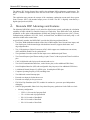
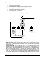
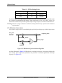
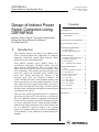
Hardware Implementation
5.
Hardware Implementation
5.1 System Outline
The hardware (HW) system is designed to drive the three-phase AC/BLDC motor. The application
note described here is only a PFC application example without motor control. PFC can be easily
integrated with any motor control application.
There are software (SW) versions targeted for a real DSP and evaluation module (DSP/EVM):
•
DSP56F803
•
DSP56F805
The HW setup only depends on the evaluation module (EVM) applied.
The designed software is capable of running only with the high voltage HW set described below.
The HW setup described in Figure 5-1 below is also described in the documents
Targetting_DSP56803_Platform, Targetting_DSP56805_Platform, both available from Motorola.
These documents also contain EVM jumper setting descriptions.
5.2 High Voltage HW Set
The PFC application does not require the motor drive. It provides evaluation of the PFC software only.
To enable a PFC converter on the high voltage 3ph AC/BLDC board, the jumper JP201 shall be in
PFC position. Contacts one and two are closed.
+12VDC
GND
U3
J1
J2
Optoisolation
Board
Controller
Board
JP201
1
2
3
3ph AC/BLDC
High Voltage
Power Stage
J1
PE
JP1.1
JP1.2
J11.1
J11.2
J14
L
N
U1
U2
40w flat ribbon
cable, gray
40w flat ribbon
cable, gray
Figure 5-1 High Voltage HW System Configuration
All the system parts are supplied and documented according to the following references:
•
U1 - Controller board for DSP56F805:
— supplied as: DSP56805EVM
— described in: DSP Evaluation Module Hardware User’s Manual
•
8
U1 - Controller board for DSP56F803:
Indirect Power Factor Correction