1
MELSEC iQ-R Motion Controller
Programming Manual (Common)
-R16MTCPU
-R32MTCPU
SAFETY PRECAUTIONS
(Read these precautions before using this product.)
Before using this product, please read this manual and the relevant manuals carefully and pay full attention to safety to handle
the product correctly.
The precautions given in this manual are concerned with this product only. Refer to the user's manual of the CPU module to
use for a description of the PLC system safety precautions.
In this manual, the safety precautions are classified into two levels: "
WARNING" and "
CAUTION".
WARNING
Indicates that incorrect handling may cause hazardous conditions, resulting in
death or severe injury.
CAUTION
Indicates that incorrect handling may cause hazardous conditions, resulting in
minor or moderate injury or property damage.
Under some circumstances, failure to observe the precautions given under "
CAUTION" may lead to serious
consequences.
Observe the precautions of both levels because they are important for personal and system safety.
Make sure that the end users read this manual and then keep the manual in a safe place for future reference.
[Design Precautions]
WARNING
● Configure safety circuits external to the programmable controller to ensure that the entire system
operates safely even when a fault occurs in the external power supply or the programmable controller.
Failure to do so may result in an accident due to an incorrect output or malfunction.
(1) Emergency stop circuits, protection circuits, and protective interlock circuits for conflicting
operations (such as forward/reverse rotations or upper/lower limit positioning) must be configured
external to the programmable controller.
(2) When the programmable controller detects an abnormal condition, it stops the operation and all
outputs are:
• Turned off if the overcurrent or overvoltage protection of the power supply module is activated.
• Held or turned off according to the parameter setting if the self-diagnostic function of the CPU
module detects an error such as a watchdog timer error.
(3) Also, all outputs may be turned on if an error occurs in a part, such as an I/O control part, where
the CPU module cannot detect any error. To ensure safety operation in such a case, provide a
safety mechanism or a fail-safe circuit external to the programmable controller. For a fail-safe
circuit example, refer to the user's manual of the CPU module to use.
(4) Outputs may remain on or off due to a failure of a component such as a relay and transistor in an
output circuit. Configure an external circuit for monitoring output signals that could cause a
serious accident.
● In an output circuit, when a load current exceeding the rated current or an overcurrent caused by a
load short-circuit flows for a long time, it may cause smoke and fire. To prevent this, configure an
external safety circuit, such as a fuse.
● Configure a circuit so that the programmable controller is turned on first and then the external power
supply. If the external power supply is turned on first, an accident may occur due to an incorrect output
or malfunction.
● For the operating status of each station after a communication failure, refer to manuals relevant to the
network. Incorrect output or malfunction due to a communication failure may result in an accident.
1
[Design Precautions]
WARNING
● When connecting an external device with a CPU module or intelligent function module to modify data
of a running programmable controller, configure an interlock circuit in the program to ensure that the
entire system will always operate safely. For other forms of control (such as program modification,
parameter change, forced output, or operating status change) of a running programmable controller,
read the relevant manuals carefully and ensure that the operation is safe before proceeding. Improper
operation may damage machines or cause accidents.
● Especially, when a remote programmable controller is controlled by an external device, immediate
action cannot be taken if a problem occurs in the programmable controller due to a communication
failure. To prevent this, configure an interlock circuit in the program, and determine corrective actions
to be taken between the external device and CPU module in case of a communication failure.
● Do not write any data to the "system area" and "write-protect area" of the buffer memory in the
module. Also, do not use any "use prohibited" signals as an output signal from the CPU module to
each module. Doing so may cause malfunction of the programmable controller system. For the
"system area", "write-protect area", and the "use prohibited" signals, refer to the user's manual for the
module used.
● If a communication cable is disconnected, the network may be unstable, resulting in a communication
failure of multiple stations. Configure an interlock circuit in the program to ensure that the entire
system will always operate safely even if communications fail. Failure to do so may result in an
accident due to an incorrect output or malfunction.
● To maintain the safety of the programmable controller system against unauthorized access from
external devices via the network, take appropriate measures. To maintain the safety against
unauthorized access via the Internet, take measures such as installing a firewall.
● Configure safety circuits external to the programmable controller to ensure that the entire system
operates safely even when a fault occurs in the external power supply or the programmable controller.
Failure to do so may result in an accident due to an incorrect output or malfunction.
● If safety standards (ex., robot safety rules, etc.,) apply to the system using the module, servo amplifier
and servomotor, make sure that the safety standards are satisfied.
● Construct a safety circuit externally of the module or servo amplifier if the abnormal operation of the
module or servo amplifier differs from the safety directive operation in the system.
● Do not remove the SSCNET cable while turning on the control circuit power supply of modules and
servo amplifier. Do not see directly the light generated from SSCNET connector of the module or
servo amplifier and the end of SSCNET cable. When the light gets into eyes, you may feel
something wrong with eyes. (The light source of SSCNET complies with class1 defined in JISC6802
or IEC60825-1.)
2
[Design Precautions]
CAUTION
● Do not install the control lines or communication cables together with the main circuit lines or power
cables. Keep a distance of 100 mm or more between them. Failure to do so may result in malfunction
due to noise.
● During control of an inductive load such as a lamp, heater, or solenoid valve, a large current
(approximately ten times greater than normal) may flow when the output is turned from off to on.
Therefore, use a module that has a sufficient current rating.
● After the CPU module is powered on or is reset, the time taken to enter the RUN status varies
depending on the system configuration, parameter settings, and/or program size. Design circuits so
that the entire system will always operate safely, regardless of the time.
● Do not power off the programmable controller or do not reset the CPU module during the setting
registration. Doing so will make the data in the flash ROM undefined. The data need to be set in the
buffer memory and to be written to the flash ROM again. Doing so may cause malfunction or failure of
the module.
● When changing the operating status of the CPU module from external devices (such as remote RUN/
STOP), select "Do Not Open by Program" for "Opening Method" in the module parameters. If "Open
by Program" is selected, an execution of remote STOP causes the communication line to close.
Consequently, the CPU module cannot reopen the communication line, and external devices cannot
execute the remote RUN.
[Installation Precautions]
WARNING
● Shut off the external power supply (all phases) used in the system before mounting or removing the
module. Failure to do so may result in electric shock or cause the module to fail or malfunction.
3
[Installation Precautions]
CAUTION
● Use the programmable controller in an environment that meets the general specifications in the
manual "Safety Guidelines" included in the base unit. Failure to do so may result in electric shock, fire,
malfunction, or damage to or deterioration of the product.
● To mount a module, place the concave part(s) located at the bottom onto the guide(s) of the base unit,
and push in the module until the hook(s) located at the top snaps into place. Incorrect mounting may
cause malfunction, failure, or drop of the module.
● When using the programmable controller in an environment of frequent vibrations, fix the module with
a screw.
● Tighten the screws within the specified torque range. Undertightening can cause drop of the screw,
short circuit, or malfunction. Overtightening can damage the screw and/or module, resulting in drop,
short circuit, or malfunction.
● When using an extension cable, connect it to the extension cable connector of the base unit securely.
Check the connection for looseness. Poor contact may cause incorrect input or output.
● When using an SD memory card, fully insert it into the memory card slot. Check that it is inserted
completely. Poor contact may cause malfunction.
● Securely insert an extended SRAM cassette into the cassette connector of a CPU module. After
insertion, close the cassette cover and check that the cassette is inserted completely. Poor contact
may cause malfunction.
● Do not directly touch any conductive parts and electronic components of the module, SD memory
card, extended SRAM cassette, or connector. Doing so may cause malfunction or failure of the
module.
[Wiring Precautions]
WARNING
● Shut off the external power supply (all phases) used in the system before installation and wiring.
Failure to do so may result in electric shock or damage to the product.
● After installation and wiring, attach the included terminal cover to the module before turning it on for
operation. Failure to do so may result in electric shock.
4
[Wiring Precautions]
CAUTION
● Individually ground the FG and LG terminals of the programmable controller with a ground resistance
of 100 ohm or less. Failure to do so may result in electric shock or malfunction.
● Use applicable solderless terminals and tighten them within the specified torque range. If any spade
solderless terminal is used, it may be disconnected when the terminal screw comes loose, resulting in
failure.
● Check the rated voltage and signal layout before wiring to the module, and connect the cables
correctly. Connecting a power supply with a different voltage rating or incorrect wiring may cause fire
or failure.
● Connectors for external devices or coaxial cables must be crimped or pressed with the tool specified
by the manufacturer, or must be correctly soldered. Incomplete connections may cause short circuit,
fire, or malfunction.
● Securely connect the connector to the module. Poor contact may cause malfunction.
● Do not install the control lines or communication cables together with the main circuit lines or power
cables. Keep a distance of 100 mm or more between them. Failure to do so may result in malfunction
due to noise.
● Place the cables in a duct or clamp them. If not, dangling cable may swing or inadvertently be pulled,
resulting in damage to the module or cables or malfunction due to poor contact. Do not clamp the
extension cables with the jacket stripped.
● Check the interface type and correctly connect the cable. Incorrect wiring (connecting the cable to an
incorrect interface) may cause failure of the module and external device.
● Tighten the terminal screws or connector screws within the specified torque range. Undertightening
can cause drop of the screw, short circuit, fire, or malfunction. Overtightening can damage the screw
and/or module, resulting in drop, short circuit, fire, or malfunction.
● When disconnecting the cable from the module, do not pull the cable by the cable part. For the cable
with connector, hold the connector part of the cable. For the cable connected to the terminal block,
loosen the terminal screw. Pulling the cable connected to the module may result in malfunction or
damage to the module or cable.
● Prevent foreign matter such as dust or wire chips from entering the module. Such foreign matter can
cause a fire, failure, or malfunction.
● A protective film is attached to the top of the module to prevent foreign matter, such as wire chips,
from entering the module during wiring. Do not remove the film during wiring. Remove it for heat
dissipation before system operation.
● Programmable controllers must be installed in control panels. Connect the main power supply to the
power supply module in the control panel through a relay terminal block. Wiring and replacement of a
power supply module must be performed by qualified maintenance personnel with knowledge of
protection against electric shock. For wiring, refer to the MELSEC iQ-R Module Configuration Manual.
● For Ethernet cables to be used in the system, select the ones that meet the specifications in the user's
manual for the module used. If not, normal data transmission is not guaranteed.
5
[Startup and Maintenance Precautions]
WARNING
● Do not touch any terminal while power is on. Doing so will cause electric shock or malfunction.
● Correctly connect the battery connector. Do not charge, disassemble, heat, short-circuit, solder, or
throw the battery into the fire. Also, do not expose it to liquid or strong shock. Doing so may cause the
battery to generate heat, explode, ignite, or leak, resulting in injury or fire.
● Shut off the external power supply (all phases) used in the system before cleaning the module or
retightening the terminal screws, connector screws, or module fixing screws. Failure to do so may
result in electric shock or cause the module to fail or malfunction.
[Startup and Maintenance Precautions]
CAUTION
● When connecting an external device with a CPU module or intelligent function module to modify data
of a running programmable controller, configure an interlock circuit in the program to ensure that the
entire system will always operate safely. For other forms of control (such as program modification,
parameter change, forced output, or operating status change) of a running programmable controller,
read the relevant manuals carefully and ensure that the operation is safe before proceeding. Improper
operation may damage machines or cause accidents.
● Especially, when a remote programmable controller is controlled by an external device, immediate
action cannot be taken if a problem occurs in the programmable controller due to a communication
failure. To prevent this, configure an interlock circuit in the program, and determine corrective actions
to be taken between the external device and CPU module in case of a communication failure.
● Do not disassemble or modify the modules. Doing so may cause failure, malfunction, injury, or a fire.
● Use any radio communication device such as a cellular phone or PHS (Personal Handyphone
System) more than 25 cm away in all directions from the programmable controller. Failure to do so
may cause malfunction.
● Shut off the external power supply (all phases) used in the system before mounting or removing the
module. Failure to do so may cause the module to fail or malfunction.
● Tighten the screws within the specified torque range. Undertightening can cause drop of the
component or wire, short circuit, or malfunction. Overtightening can damage the screw and/or module,
resulting in drop, short circuit, or malfunction.
● After the first use of the product, do not mount/remove the module to/from the base unit, and the
terminal block to/from the module, and do not insert/remove the extended SRAM cassette to/from the
CPU module more than 50 times (IEC 61131-2 compliant) respectively. Exceeding the limit of 50 times
may cause malfunction.
● After the first use of the product, do not insert/remove the SD memory card to/from the CPU module
more than 500 times. Exceeding the limit may cause malfunction.
● Do not touch the metal terminals on the back side of the SD memory card. Doing so may cause
malfunction or failure.
● Do not touch the integrated circuits on the circuit board of an extended SRAM cassette. Doing so may
cause malfunction or failure.
● Do not drop or apply shock to the battery to be installed in the module. Doing so may damage the
battery, causing the battery fluid to leak inside the battery. If the battery is dropped or any shock is
applied to it, dispose of it without using.
6
[Startup and Maintenance Precautions]
CAUTION
● Startup and maintenance of a control panel must be performed by qualified maintenance personnel
with knowledge of protection against electric shock. Lock the control panel so that only qualified
maintenance personnel can operate it.
● Before handling the module, touch a conducting object such as a grounded metal to discharge the
static electricity from the human body. Failure to do so may cause the module to fail or malfunction.
● Before testing the operation, set a low speed value for the speed limit parameter so that the operation
can be stopped immediately upon occurrence of a hazardous condition.
● Confirm and adjust the program and each parameter before operation. Unpredictable movements
may occur depending on the machine.
● When using the absolute position system function, on starting up, and when the module or absolute
position motor has been replaced, always perform a home position return.
● Before starting the operation, confirm the brake function.
● Do not perform a megger test (insulation resistance measurement) during inspection.
● After maintenance and inspections are completed, confirm that the position detection of the absolute
position detection function is correct.
● Lock the control panel and prevent access to those who are not certified to handle or install electric
equipment.
[Operating Precautions]
CAUTION
● When changing data and operating status, and modifying program of the running programmable
controller from an external device such as a personal computer connected to an intelligent function
module, read relevant manuals carefully and ensure the safety before operation. Incorrect change or
modification may cause system malfunction, damage to the machines, or accidents.
● Do not power off the programmable controller or reset the CPU module while the setting values in the
buffer memory are being written to the flash ROM in the module. Doing so will make the data in the
flash ROM undefined. The values need to be set in the buffer memory and written to the flash ROM
again. Doing so also can cause malfunction or failure of the module.
● Note that when the reference axis speed is specified for interpolation operation, the speed of the
partner axis (2nd, 3rd, or 4th axis) may exceed the speed limit value.
● Do not go near the machine during test operations or during operations such as teaching. Doing so
may lead to injuries.
[Disposal Precautions]
CAUTION
● When disposing of this product, treat it as industrial waste.
● When disposing of batteries, separate them from other wastes according to the local regulations. For
details on battery regulations in EU member states, refer to the MELSEC iQ-R Module Configuration
Manual.
7
[Transportation Precautions]
CAUTION
● When transporting lithium batteries, follow the transportation regulations. For details on the regulated
models, refer to the MELSEC iQ-R Module Configuration Manual.
● The halogens (such as fluorine, chlorine, bromine, and iodine), which are contained in a fumigant
used for disinfection and pest control of wood packaging materials, may cause failure of the product.
Prevent the entry of fumigant residues into the product or consider other methods (such as heat
treatment) instead of fumigation. The disinfection and pest control measures must be applied to
unprocessed raw wood.
8
CONDITIONS OF USE FOR THE PRODUCT
(1) Mitsubishi programmable controller ("the PRODUCT") shall be used in conditions;
i) where any problem, fault or failure occurring in the PRODUCT, if any, shall not lead to any major or serious accident;
and
ii) where the backup and fail-safe function are systematically or automatically provided outside of the PRODUCT for the
case of any problem, fault or failure occurring in the PRODUCT.
(2) The PRODUCT has been designed and manufactured for the purpose of being used in general industries.
MITSUBISHI SHALL HAVE NO RESPONSIBILITY OR LIABILITY (INCLUDING, BUT NOT LIMITED TO ANY AND ALL
RESPONSIBILITY OR LIABILITY BASED ON CONTRACT, WARRANTY, TORT, PRODUCT LIABILITY) FOR ANY
INJURY OR DEATH TO PERSONS OR LOSS OR DAMAGE TO PROPERTY CAUSED BY the PRODUCT THAT ARE
OPERATED OR USED IN APPLICATION NOT INTENDED OR EXCLUDED BY INSTRUCTIONS, PRECAUTIONS, OR
WARNING CONTAINED IN MITSUBISHI'S USER, INSTRUCTION AND/OR SAFETY MANUALS, TECHNICAL
BULLETINS AND GUIDELINES FOR the PRODUCT.
("Prohibited Application")
Prohibited Applications include, but not limited to, the use of the PRODUCT in;
• Nuclear Power Plants and any other power plants operated by Power companies, and/or any other cases in which the
public could be affected if any problem or fault occurs in the PRODUCT.
• Railway companies or Public service purposes, and/or any other cases in which establishment of a special quality
assurance system is required by the Purchaser or End User.
• Aircraft or Aerospace, Medical applications, Train equipment, transport equipment such as Elevator and Escalator,
Incineration and Fuel devices, Vehicles, Manned transportation, Equipment for Recreation and Amusement, and
Safety devices, handling of Nuclear or Hazardous Materials or Chemicals, Mining and Drilling, and/or other
applications where there is a significant risk of injury to the public or property.
Notwithstanding the above, restrictions Mitsubishi may in its sole discretion, authorize use of the PRODUCT in one or
more of the Prohibited Applications, provided that the usage of the PRODUCT is limited only for the specific
applications agreed to by Mitsubishi and provided further that no special quality assurance or fail-safe, redundant or
other safety features which exceed the general specifications of the PRODUCTs are required. For details, please
contact the Mitsubishi representative in your region.
INTRODUCTION
Thank you for purchasing the Mitsubishi MELSEC iQ-R series programmable controllers.
This manual describes the specifications, procedures before operation and wiring of the relevant products listed below.
Before using this product, please read this manual and the relevant manuals carefully and develop familiarity with the
functions and performance of the MELSEC iQ-R series programmable controller to handle the product correctly.
When applying the program examples provided in this manual to an actual system, ensure the applicability and confirm that it
will not cause system control problems.
Please make sure that the end users read this manual.
Relevant products
R16MTCPU, R32MTCPU
9
COMPLIANCE WITH EMC AND LOW VOLTAGE
DIRECTIVES
Method of ensuring compliance
To ensure that Mitsubishi programmable controllers maintain EMC and Low Voltage Directives when incorporated into other
machinery or equipment, certain measures may be necessary. Please refer to one of the following manuals.
MELSEC iQ-R Module Configuration Manual
Safety Guidelines (This manual is included with the base unit.)
The CE mark on the side of the programmable controller indicates compliance with EMC and Low Voltage Directives.
Additional measures
To ensure that this product maintains EMC and Low Voltage Directives, please refer to the following manual.
MELSEC iQ-R Motion Controller User's Manual
10
CONTENTS
SAFETY PRECAUTIONS . . . . . . . . . . . . . . . . . . . . . . . . . . . . . . . . . . . . . . . . . . . . . . . . . . . . . . . . . . . . . . . . . . . .1
CONDITIONS OF USE FOR THE PRODUCT . . . . . . . . . . . . . . . . . . . . . . . . . . . . . . . . . . . . . . . . . . . . . . . . . . . .9
INTRODUCTION . . . . . . . . . . . . . . . . . . . . . . . . . . . . . . . . . . . . . . . . . . . . . . . . . . . . . . . . . . . . . . . . . . . . . . . . . . .9
COMPLIANCE WITH EMC AND LOW VOLTAGE DIRECTIVES . . . . . . . . . . . . . . . . . . . . . . . . . . . . . . . . . . . . .10
RELEVANT MANUALS . . . . . . . . . . . . . . . . . . . . . . . . . . . . . . . . . . . . . . . . . . . . . . . . . . . . . . . . . . . . . . . . . . . . .16
MANUAL PAGE ORGANIZATION. . . . . . . . . . . . . . . . . . . . . . . . . . . . . . . . . . . . . . . . . . . . . . . . . . . . . . . . . . . . .18
CHAPTER 1
1.1
MULTIPLE CPU SYSTEM
19
Multiple CPU System. . . . . . . . . . . . . . . . . . . . . . . . . . . . . . . . . . . . . . . . . . . . . . . . . . . . . . . . . . . . . . . . . . . . . 19
Overview . . . . . . . . . . . . . . . . . . . . . . . . . . . . . . . . . . . . . . . . . . . . . . . . . . . . . . . . . . . . . . . . . . . . . . . . . . . . . . . 19
Restrictions on Multiple CPU systems using Motion CPUs. . . . . . . . . . . . . . . . . . . . . . . . . . . . . . . . . . . . . . . . . 20
Module control with Motion CPUs . . . . . . . . . . . . . . . . . . . . . . . . . . . . . . . . . . . . . . . . . . . . . . . . . . . . . . . . . . . . 22
1.2
CONTENTS
TERMS . . . . . . . . . . . . . . . . . . . . . . . . . . . . . . . . . . . . . . . . . . . . . . . . . . . . . . . . . . . . . . . . . . . . . . . . . . . . . . . . .17
Setting Operation for Multiple CPU System . . . . . . . . . . . . . . . . . . . . . . . . . . . . . . . . . . . . . . . . . . . . . . . . . . 24
Setting operation for CPU module stop error . . . . . . . . . . . . . . . . . . . . . . . . . . . . . . . . . . . . . . . . . . . . . . . . . . . 24
Multiple CPU synchronous startup setting. . . . . . . . . . . . . . . . . . . . . . . . . . . . . . . . . . . . . . . . . . . . . . . . . . . . . . 24
Clock synchronization between Multiple CPU . . . . . . . . . . . . . . . . . . . . . . . . . . . . . . . . . . . . . . . . . . . . . . . . . . . 24
1.3
Data Communication Between CPU Modules in the Multiple CPU System . . . . . . . . . . . . . . . . . . . . . . . . . 25
Used memory . . . . . . . . . . . . . . . . . . . . . . . . . . . . . . . . . . . . . . . . . . . . . . . . . . . . . . . . . . . . . . . . . . . . . . . . . . . 25
Data communication by refreshing at Motion CPUs . . . . . . . . . . . . . . . . . . . . . . . . . . . . . . . . . . . . . . . . . . . . . . 27
Fixed scan data transmission section over check . . . . . . . . . . . . . . . . . . . . . . . . . . . . . . . . . . . . . . . . . . . . . . . . 32
Inter-module synchronization function. . . . . . . . . . . . . . . . . . . . . . . . . . . . . . . . . . . . . . . . . . . . . . . . . . . . . . . . . 33
Relationship between fixed scan communication and inter-module synchronization . . . . . . . . . . . . . . . . . . . . . 41
Control instruction from PLC CPU to Motion CPU . . . . . . . . . . . . . . . . . . . . . . . . . . . . . . . . . . . . . . . . . . . . . . . 42
CHAPTER 2
COMMON PARAMETERS
43
2.1
Parameters Used by the Motion CPU . . . . . . . . . . . . . . . . . . . . . . . . . . . . . . . . . . . . . . . . . . . . . . . . . . . . . . . 43
2.2
R Series Common Parameter . . . . . . . . . . . . . . . . . . . . . . . . . . . . . . . . . . . . . . . . . . . . . . . . . . . . . . . . . . . . . . 45
System parameter . . . . . . . . . . . . . . . . . . . . . . . . . . . . . . . . . . . . . . . . . . . . . . . . . . . . . . . . . . . . . . . . . . . . . . . . 46
CPU parameter . . . . . . . . . . . . . . . . . . . . . . . . . . . . . . . . . . . . . . . . . . . . . . . . . . . . . . . . . . . . . . . . . . . . . . . . . . 48
Module Parameter . . . . . . . . . . . . . . . . . . . . . . . . . . . . . . . . . . . . . . . . . . . . . . . . . . . . . . . . . . . . . . . . . . . . . . . . 52
2.3
Motion CPU Common Parameter . . . . . . . . . . . . . . . . . . . . . . . . . . . . . . . . . . . . . . . . . . . . . . . . . . . . . . . . . . . 53
Basic setting . . . . . . . . . . . . . . . . . . . . . . . . . . . . . . . . . . . . . . . . . . . . . . . . . . . . . . . . . . . . . . . . . . . . . . . . . . . . 54
Servo network setting . . . . . . . . . . . . . . . . . . . . . . . . . . . . . . . . . . . . . . . . . . . . . . . . . . . . . . . . . . . . . . . . . . . . . 56
Manual pulse generator connection setting. . . . . . . . . . . . . . . . . . . . . . . . . . . . . . . . . . . . . . . . . . . . . . . . . . . . . 61
2.4
Motion CPU Operating Status . . . . . . . . . . . . . . . . . . . . . . . . . . . . . . . . . . . . . . . . . . . . . . . . . . . . . . . . . . . . . 62
Initial processing . . . . . . . . . . . . . . . . . . . . . . . . . . . . . . . . . . . . . . . . . . . . . . . . . . . . . . . . . . . . . . . . . . . . . . . . . 62
RUN/STOP status control . . . . . . . . . . . . . . . . . . . . . . . . . . . . . . . . . . . . . . . . . . . . . . . . . . . . . . . . . . . . . . . . . . 64
CHAPTER 3
3.1
DEVICES
66
Device List . . . . . . . . . . . . . . . . . . . . . . . . . . . . . . . . . . . . . . . . . . . . . . . . . . . . . . . . . . . . . . . . . . . . . . . . . . . . . 66
Devices that can be used with each function . . . . . . . . . . . . . . . . . . . . . . . . . . . . . . . . . . . . . . . . . . . . . . . . . . . 68
3.2
User Device . . . . . . . . . . . . . . . . . . . . . . . . . . . . . . . . . . . . . . . . . . . . . . . . . . . . . . . . . . . . . . . . . . . . . . . . . . . . 70
Input (X). . . . . . . . . . . . . . . . . . . . . . . . . . . . . . . . . . . . . . . . . . . . . . . . . . . . . . . . . . . . . . . . . . . . . . . . . . . . . . . . 70
Output (Y) . . . . . . . . . . . . . . . . . . . . . . . . . . . . . . . . . . . . . . . . . . . . . . . . . . . . . . . . . . . . . . . . . . . . . . . . . . . . . . 70
Internal relay (M) . . . . . . . . . . . . . . . . . . . . . . . . . . . . . . . . . . . . . . . . . . . . . . . . . . . . . . . . . . . . . . . . . . . . . . . . . 70
Link relay (B) . . . . . . . . . . . . . . . . . . . . . . . . . . . . . . . . . . . . . . . . . . . . . . . . . . . . . . . . . . . . . . . . . . . . . . . . . . . . 70
Annunciator (F) . . . . . . . . . . . . . . . . . . . . . . . . . . . . . . . . . . . . . . . . . . . . . . . . . . . . . . . . . . . . . . . . . . . . . . . . . . 70
11
Data register (D) . . . . . . . . . . . . . . . . . . . . . . . . . . . . . . . . . . . . . . . . . . . . . . . . . . . . . . . . . . . . . . . . . . . . . . . . . 70
Link register (W) . . . . . . . . . . . . . . . . . . . . . . . . . . . . . . . . . . . . . . . . . . . . . . . . . . . . . . . . . . . . . . . . . . . . . . . . . 70
Motion register (#) . . . . . . . . . . . . . . . . . . . . . . . . . . . . . . . . . . . . . . . . . . . . . . . . . . . . . . . . . . . . . . . . . . . . . . . . 70
3.3
System Device . . . . . . . . . . . . . . . . . . . . . . . . . . . . . . . . . . . . . . . . . . . . . . . . . . . . . . . . . . . . . . . . . . . . . . . . . . 71
Special relay (SM) . . . . . . . . . . . . . . . . . . . . . . . . . . . . . . . . . . . . . . . . . . . . . . . . . . . . . . . . . . . . . . . . . . . . . . . . 71
Special register (SD) . . . . . . . . . . . . . . . . . . . . . . . . . . . . . . . . . . . . . . . . . . . . . . . . . . . . . . . . . . . . . . . . . . . . . . 71
3.4
CPU Buffer Memory Access Device . . . . . . . . . . . . . . . . . . . . . . . . . . . . . . . . . . . . . . . . . . . . . . . . . . . . . . . . 71
3.5
Module Access Device . . . . . . . . . . . . . . . . . . . . . . . . . . . . . . . . . . . . . . . . . . . . . . . . . . . . . . . . . . . . . . . . . . . 72
3.6
Constants . . . . . . . . . . . . . . . . . . . . . . . . . . . . . . . . . . . . . . . . . . . . . . . . . . . . . . . . . . . . . . . . . . . . . . . . . . . . . . 72
3.7
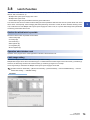
Device Setting . . . . . . . . . . . . . . . . . . . . . . . . . . . . . . . . . . . . . . . . . . . . . . . . . . . . . . . . . . . . . . . . . . . . . . . . . . 73
3.8
Latch Function. . . . . . . . . . . . . . . . . . . . . . . . . . . . . . . . . . . . . . . . . . . . . . . . . . . . . . . . . . . . . . . . . . . . . . . . . . 75
3.9
Labels . . . . . . . . . . . . . . . . . . . . . . . . . . . . . . . . . . . . . . . . . . . . . . . . . . . . . . . . . . . . . . . . . . . . . . . . . . . . . . . . . 77
Labels registered in the Motion CPU. . . . . . . . . . . . . . . . . . . . . . . . . . . . . . . . . . . . . . . . . . . . . . . . . . . . . . . . . . 77
Classes . . . . . . . . . . . . . . . . . . . . . . . . . . . . . . . . . . . . . . . . . . . . . . . . . . . . . . . . . . . . . . . . . . . . . . . . . . . . . . . . 77
Data types . . . . . . . . . . . . . . . . . . . . . . . . . . . . . . . . . . . . . . . . . . . . . . . . . . . . . . . . . . . . . . . . . . . . . . . . . . . . . . 77
Structures . . . . . . . . . . . . . . . . . . . . . . . . . . . . . . . . . . . . . . . . . . . . . . . . . . . . . . . . . . . . . . . . . . . . . . . . . . . . . . 78
CHAPTER 4
4.1
AUXILIARY AND APPLIED FUNCTIONS
79
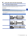
Limit Switch Output Function . . . . . . . . . . . . . . . . . . . . . . . . . . . . . . . . . . . . . . . . . . . . . . . . . . . . . . . . . . . . . 79
Operations . . . . . . . . . . . . . . . . . . . . . . . . . . . . . . . . . . . . . . . . . . . . . . . . . . . . . . . . . . . . . . . . . . . . . . . . . . . . . . 79
Limit output data setting . . . . . . . . . . . . . . . . . . . . . . . . . . . . . . . . . . . . . . . . . . . . . . . . . . . . . . . . . . . . . . . . . . . 81
4.2
External Input Signal. . . . . . . . . . . . . . . . . . . . . . . . . . . . . . . . . . . . . . . . . . . . . . . . . . . . . . . . . . . . . . . . . . . . . 85
External signal . . . . . . . . . . . . . . . . . . . . . . . . . . . . . . . . . . . . . . . . . . . . . . . . . . . . . . . . . . . . . . . . . . . . . . . . . . . 85
High-speed Input Request Signal . . . . . . . . . . . . . . . . . . . . . . . . . . . . . . . . . . . . . . . . . . . . . . . . . . . . . . . . . . . . 86
4.3
Mark Detection Function. . . . . . . . . . . . . . . . . . . . . . . . . . . . . . . . . . . . . . . . . . . . . . . . . . . . . . . . . . . . . . . . . . 89
Operations . . . . . . . . . . . . . . . . . . . . . . . . . . . . . . . . . . . . . . . . . . . . . . . . . . . . . . . . . . . . . . . . . . . . . . . . . . . . . . 90
Mark detection setting . . . . . . . . . . . . . . . . . . . . . . . . . . . . . . . . . . . . . . . . . . . . . . . . . . . . . . . . . . . . . . . . . . . . . 91
4.4
Servo ON/OFF . . . . . . . . . . . . . . . . . . . . . . . . . . . . . . . . . . . . . . . . . . . . . . . . . . . . . . . . . . . . . . . . . . . . . . . . . . 97
Servo ON/OFF. . . . . . . . . . . . . . . . . . . . . . . . . . . . . . . . . . . . . . . . . . . . . . . . . . . . . . . . . . . . . . . . . . . . . . . . . . . 97
Follow up function . . . . . . . . . . . . . . . . . . . . . . . . . . . . . . . . . . . . . . . . . . . . . . . . . . . . . . . . . . . . . . . . . . . . . . . . 98
4.5
Absolute Position System . . . . . . . . . . . . . . . . . . . . . . . . . . . . . . . . . . . . . . . . . . . . . . . . . . . . . . . . . . . . . . . . 99
Absolute position system. . . . . . . . . . . . . . . . . . . . . . . . . . . . . . . . . . . . . . . . . . . . . . . . . . . . . . . . . . . . . . . . . . . 99
Synchronous control absolute position system . . . . . . . . . . . . . . . . . . . . . . . . . . . . . . . . . . . . . . . . . . . . . . . . . 101
Saving and recovering backup data . . . . . . . . . . . . . . . . . . . . . . . . . . . . . . . . . . . . . . . . . . . . . . . . . . . . . . . . . 101
4.6
Clock Function. . . . . . . . . . . . . . . . . . . . . . . . . . . . . . . . . . . . . . . . . . . . . . . . . . . . . . . . . . . . . . . . . . . . . . . . . 102
4.7
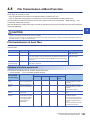
File Transfer Function . . . . . . . . . . . . . . . . . . . . . . . . . . . . . . . . . . . . . . . . . . . . . . . . . . . . . . . . . . . . . . . . . . . 103
4.8
File Transmission at Boot Function. . . . . . . . . . . . . . . . . . . . . . . . . . . . . . . . . . . . . . . . . . . . . . . . . . . . . . . . 107
File transmission at boot files . . . . . . . . . . . . . . . . . . . . . . . . . . . . . . . . . . . . . . . . . . . . . . . . . . . . . . . . . . . . . . 107
File transmission at boot procedure . . . . . . . . . . . . . . . . . . . . . . . . . . . . . . . . . . . . . . . . . . . . . . . . . . . . . . . . . 111
Operation when security function is set. . . . . . . . . . . . . . . . . . . . . . . . . . . . . . . . . . . . . . . . . . . . . . . . . . . . . . . 112
CHAPTER 5
5.1
FUNCTIONS USED WITH SSCNET COMMUNICATION
114
Servo Parameter Management . . . . . . . . . . . . . . . . . . . . . . . . . . . . . . . . . . . . . . . . . . . . . . . . . . . . . . . . . . . . 114
Transmission of servo parameters . . . . . . . . . . . . . . . . . . . . . . . . . . . . . . . . . . . . . . . . . . . . . . . . . . . . . . . . . . 114
Servo Parameter Read/Change Function . . . . . . . . . . . . . . . . . . . . . . . . . . . . . . . . . . . . . . . . . . . . . . . . . . . . . 116
5.2
Optional Data Monitor Function . . . . . . . . . . . . . . . . . . . . . . . . . . . . . . . . . . . . . . . . . . . . . . . . . . . . . . . . . . . 117
Optional data monitor setting. . . . . . . . . . . . . . . . . . . . . . . . . . . . . . . . . . . . . . . . . . . . . . . . . . . . . . . . . . . . . . . 120
Example of using transient commands . . . . . . . . . . . . . . . . . . . . . . . . . . . . . . . . . . . . . . . . . . . . . . . . . . . . . . . 126
5.3
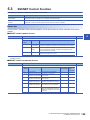
SSCNET Control Function . . . . . . . . . . . . . . . . . . . . . . . . . . . . . . . . . . . . . . . . . . . . . . . . . . . . . . . . . . . . . . . 129
Connect/disconnect function of SSCNET communication. . . . . . . . . . . . . . . . . . . . . . . . . . . . . . . . . . . . . . . . . 130
12
Amplifier-less operation function . . . . . . . . . . . . . . . . . . . . . . . . . . . . . . . . . . . . . . . . . . . . . . . . . . . . . . . . . . . . 133
5.4
Driver Communication Function . . . . . . . . . . . . . . . . . . . . . . . . . . . . . . . . . . . . . . . . . . . . . . . . . . . . . . . . . . 137
Control details . . . . . . . . . . . . . . . . . . . . . . . . . . . . . . . . . . . . . . . . . . . . . . . . . . . . . . . . . . . . . . . . . . . . . . . . . . 137
Precautions during control. . . . . . . . . . . . . . . . . . . . . . . . . . . . . . . . . . . . . . . . . . . . . . . . . . . . . . . . . . . . . . . . . 138
Servo parameter . . . . . . . . . . . . . . . . . . . . . . . . . . . . . . . . . . . . . . . . . . . . . . . . . . . . . . . . . . . . . . . . . . . . . . . . 140
5.5
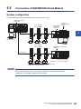
Connection of SSCNETIII/H Head Module. . . . . . . . . . . . . . . . . . . . . . . . . . . . . . . . . . . . . . . . . . . . . . . . . . . 141
System configuration . . . . . . . . . . . . . . . . . . . . . . . . . . . . . . . . . . . . . . . . . . . . . . . . . . . . . . . . . . . . . . . . . . . . . 141
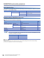
SSCNETIII/H head module parameters . . . . . . . . . . . . . . . . . . . . . . . . . . . . . . . . . . . . . . . . . . . . . . . . . . . . . . 142
Data of refresh device . . . . . . . . . . . . . . . . . . . . . . . . . . . . . . . . . . . . . . . . . . . . . . . . . . . . . . . . . . . . . . . . . . . . 147
Precautions when using SSCNETIII/H head module . . . . . . . . . . . . . . . . . . . . . . . . . . . . . . . . . . . . . . . . . . . . 147
5.6
Compatible Devices with SSCNETIII(/H) . . . . . . . . . . . . . . . . . . . . . . . . . . . . . . . . . . . . . . . . . . . . . . . . . . . . 148
Servo driver VCII series manufactured by Nikki Denso Co., Ltd. . . . . . . . . . . . . . . . . . . . . . . . . . . . . . . . . . . . 148
Inverter FR-A700 series . . . . . . . . . . . . . . . . . . . . . . . . . . . . . . . . . . . . . . . . . . . . . . . . . . . . . . . . . . . . . . . . . . 159
Optical hub unit . . . . . . . . . . . . . . . . . . . . . . . . . . . . . . . . . . . . . . . . . . . . . . . . . . . . . . . . . . . . . . . . . . . . . . . . . 168
CHAPTER 6
COMMUNICATION FUNCTIONS
CONTENTS
Data operation of intelligent function module by Motion SFC program . . . . . . . . . . . . . . . . . . . . . . . . . . . . . . . 147
172
6.1
Communication Function List . . . . . . . . . . . . . . . . . . . . . . . . . . . . . . . . . . . . . . . . . . . . . . . . . . . . . . . . . . . . 172
6.2
Security Function . . . . . . . . . . . . . . . . . . . . . . . . . . . . . . . . . . . . . . . . . . . . . . . . . . . . . . . . . . . . . . . . . . . . . . 173
File password . . . . . . . . . . . . . . . . . . . . . . . . . . . . . . . . . . . . . . . . . . . . . . . . . . . . . . . . . . . . . . . . . . . . . . . . . . 173
Software security key authentication . . . . . . . . . . . . . . . . . . . . . . . . . . . . . . . . . . . . . . . . . . . . . . . . . . . . . . . . . 175
IP filter function . . . . . . . . . . . . . . . . . . . . . . . . . . . . . . . . . . . . . . . . . . . . . . . . . . . . . . . . . . . . . . . . . . . . . . . . . 180
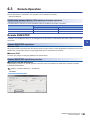
6.3
Remote Operation . . . . . . . . . . . . . . . . . . . . . . . . . . . . . . . . . . . . . . . . . . . . . . . . . . . . . . . . . . . . . . . . . . . . . . 181
Remote RUN/STOP . . . . . . . . . . . . . . . . . . . . . . . . . . . . . . . . . . . . . . . . . . . . . . . . . . . . . . . . . . . . . . . . . . . . . 181
6.4
Communication Function via PERIPHERAL I/F . . . . . . . . . . . . . . . . . . . . . . . . . . . . . . . . . . . . . . . . . . . . . . 183
Direct connection. . . . . . . . . . . . . . . . . . . . . . . . . . . . . . . . . . . . . . . . . . . . . . . . . . . . . . . . . . . . . . . . . . . . . . . . 183
Connection via HUB . . . . . . . . . . . . . . . . . . . . . . . . . . . . . . . . . . . . . . . . . . . . . . . . . . . . . . . . . . . . . . . . . . . . . 186
6.5
Vision System Connection Function . . . . . . . . . . . . . . . . . . . . . . . . . . . . . . . . . . . . . . . . . . . . . . . . . . . . . . . 191
Vision system parameter setting . . . . . . . . . . . . . . . . . . . . . . . . . . . . . . . . . . . . . . . . . . . . . . . . . . . . . . . . . . . . 195
Flow of vision system control. . . . . . . . . . . . . . . . . . . . . . . . . . . . . . . . . . . . . . . . . . . . . . . . . . . . . . . . . . . . . . . 204
Sample program . . . . . . . . . . . . . . . . . . . . . . . . . . . . . . . . . . . . . . . . . . . . . . . . . . . . . . . . . . . . . . . . . . . . . . . . 205
6.6
Test Mode . . . . . . . . . . . . . . . . . . . . . . . . . . . . . . . . . . . . . . . . . . . . . . . . . . . . . . . . . . . . . . . . . . . . . . . . . . . . . 208
Test mode specifications . . . . . . . . . . . . . . . . . . . . . . . . . . . . . . . . . . . . . . . . . . . . . . . . . . . . . . . . . . . . . . . . . . 208
Differences between normal operation and test operation . . . . . . . . . . . . . . . . . . . . . . . . . . . . . . . . . . . . . . . . 209
Parameters used during test mode . . . . . . . . . . . . . . . . . . . . . . . . . . . . . . . . . . . . . . . . . . . . . . . . . . . . . . . . . . 209
Test mode transition/cancellation . . . . . . . . . . . . . . . . . . . . . . . . . . . . . . . . . . . . . . . . . . . . . . . . . . . . . . . . . . . 210
Stop processing of axes operating in test mode . . . . . . . . . . . . . . . . . . . . . . . . . . . . . . . . . . . . . . . . . . . . . . . . 210
6.7
Positioning Control Monitor Function. . . . . . . . . . . . . . . . . . . . . . . . . . . . . . . . . . . . . . . . . . . . . . . . . . . . . . 212
Scroll monitor. . . . . . . . . . . . . . . . . . . . . . . . . . . . . . . . . . . . . . . . . . . . . . . . . . . . . . . . . . . . . . . . . . . . . . . . . . . 212
Current value history monitor . . . . . . . . . . . . . . . . . . . . . . . . . . . . . . . . . . . . . . . . . . . . . . . . . . . . . . . . . . . . . . 213
Speed monitor . . . . . . . . . . . . . . . . . . . . . . . . . . . . . . . . . . . . . . . . . . . . . . . . . . . . . . . . . . . . . . . . . . . . . . . . . . 214
6.8
Label Access from External Devices. . . . . . . . . . . . . . . . . . . . . . . . . . . . . . . . . . . . . . . . . . . . . . . . . . . . . . . 215
CHAPTER 7
DIGITAL OSCILLOSCOPE
217
7.1
Features . . . . . . . . . . . . . . . . . . . . . . . . . . . . . . . . . . . . . . . . . . . . . . . . . . . . . . . . . . . . . . . . . . . . . . . . . . . . . . 217
7.2
Function Overview . . . . . . . . . . . . . . . . . . . . . . . . . . . . . . . . . . . . . . . . . . . . . . . . . . . . . . . . . . . . . . . . . . . . . 217
7.3
Digital Oscilloscope Specifications . . . . . . . . . . . . . . . . . . . . . . . . . . . . . . . . . . . . . . . . . . . . . . . . . . . . . . . . 218
7.4
Digital Oscilloscope Operating Procedure . . . . . . . . . . . . . . . . . . . . . . . . . . . . . . . . . . . . . . . . . . . . . . . . . . 219
7.5
Sampling Settings File . . . . . . . . . . . . . . . . . . . . . . . . . . . . . . . . . . . . . . . . . . . . . . . . . . . . . . . . . . . . . . . . . . 219
7.6
Sampling Functions . . . . . . . . . . . . . . . . . . . . . . . . . . . . . . . . . . . . . . . . . . . . . . . . . . . . . . . . . . . . . . . . . . . . 220
13
Sampling type . . . . . . . . . . . . . . . . . . . . . . . . . . . . . . . . . . . . . . . . . . . . . . . . . . . . . . . . . . . . . . . . . . . . . . . . . . 220
Sampling start settings . . . . . . . . . . . . . . . . . . . . . . . . . . . . . . . . . . . . . . . . . . . . . . . . . . . . . . . . . . . . . . . . . . . 220
Sampling interval . . . . . . . . . . . . . . . . . . . . . . . . . . . . . . . . . . . . . . . . . . . . . . . . . . . . . . . . . . . . . . . . . . . . . . . . 221
Sampling target . . . . . . . . . . . . . . . . . . . . . . . . . . . . . . . . . . . . . . . . . . . . . . . . . . . . . . . . . . . . . . . . . . . . . . . . . 221
Trigger settings . . . . . . . . . . . . . . . . . . . . . . . . . . . . . . . . . . . . . . . . . . . . . . . . . . . . . . . . . . . . . . . . . . . . . . . . . 222
Saving sampling results. . . . . . . . . . . . . . . . . . . . . . . . . . . . . . . . . . . . . . . . . . . . . . . . . . . . . . . . . . . . . . . . . . . 224
7.7
Digital Oscilloscope Status . . . . . . . . . . . . . . . . . . . . . . . . . . . . . . . . . . . . . . . . . . . . . . . . . . . . . . . . . . . . . . 225
7.8
Digital Oscilloscope Errors . . . . . . . . . . . . . . . . . . . . . . . . . . . . . . . . . . . . . . . . . . . . . . . . . . . . . . . . . . . . . . 226
CHAPTER 8
8.1
MOTION CPU MEMORY STRUCTURE
227
Memory and Files . . . . . . . . . . . . . . . . . . . . . . . . . . . . . . . . . . . . . . . . . . . . . . . . . . . . . . . . . . . . . . . . . . . . . . 227
Standard ROM/SD memory card specifications . . . . . . . . . . . . . . . . . . . . . . . . . . . . . . . . . . . . . . . . . . . . . . . . 227
File handling precautions. . . . . . . . . . . . . . . . . . . . . . . . . . . . . . . . . . . . . . . . . . . . . . . . . . . . . . . . . . . . . . . . . . 228
Stored files. . . . . . . . . . . . . . . . . . . . . . . . . . . . . . . . . . . . . . . . . . . . . . . . . . . . . . . . . . . . . . . . . . . . . . . . . . . . . 229
8.2
SD Memory Card . . . . . . . . . . . . . . . . . . . . . . . . . . . . . . . . . . . . . . . . . . . . . . . . . . . . . . . . . . . . . . . . . . . . . . . 231
SD memory card handling . . . . . . . . . . . . . . . . . . . . . . . . . . . . . . . . . . . . . . . . . . . . . . . . . . . . . . . . . . . . . . . . . 231
SD memory card forced stop. . . . . . . . . . . . . . . . . . . . . . . . . . . . . . . . . . . . . . . . . . . . . . . . . . . . . . . . . . . . . . . 231
8.3
Memory Initialization . . . . . . . . . . . . . . . . . . . . . . . . . . . . . . . . . . . . . . . . . . . . . . . . . . . . . . . . . . . . . . . . . . . . 233
8.4
Installing the Operating System Software. . . . . . . . . . . . . . . . . . . . . . . . . . . . . . . . . . . . . . . . . . . . . . . . . . . 234
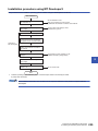
Installation procedure using MT Developer2 . . . . . . . . . . . . . . . . . . . . . . . . . . . . . . . . . . . . . . . . . . . . . . . . . . . 235
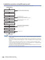
Installation procedure using SD memory card. . . . . . . . . . . . . . . . . . . . . . . . . . . . . . . . . . . . . . . . . . . . . . . . . . 236
8.5
Add-on Function . . . . . . . . . . . . . . . . . . . . . . . . . . . . . . . . . . . . . . . . . . . . . . . . . . . . . . . . . . . . . . . . . . . . . . . 237
Add-on module structure . . . . . . . . . . . . . . . . . . . . . . . . . . . . . . . . . . . . . . . . . . . . . . . . . . . . . . . . . . . . . . . . . . 238
Installing add-on library . . . . . . . . . . . . . . . . . . . . . . . . . . . . . . . . . . . . . . . . . . . . . . . . . . . . . . . . . . . . . . . . . . . 238
Add-on function load error . . . . . . . . . . . . . . . . . . . . . . . . . . . . . . . . . . . . . . . . . . . . . . . . . . . . . . . . . . . . . . . . . 238
CHAPTER 9
9.1
RAS FUNCTIONS
239
Self-Diagnostics Function . . . . . . . . . . . . . . . . . . . . . . . . . . . . . . . . . . . . . . . . . . . . . . . . . . . . . . . . . . . . . . . 239
Self-diagnostics timing. . . . . . . . . . . . . . . . . . . . . . . . . . . . . . . . . . . . . . . . . . . . . . . . . . . . . . . . . . . . . . . . . . . . 239
Error checking methods. . . . . . . . . . . . . . . . . . . . . . . . . . . . . . . . . . . . . . . . . . . . . . . . . . . . . . . . . . . . . . . . . . . 239
Operations at error detection. . . . . . . . . . . . . . . . . . . . . . . . . . . . . . . . . . . . . . . . . . . . . . . . . . . . . . . . . . . . . . . 241
Cancelling errors . . . . . . . . . . . . . . . . . . . . . . . . . . . . . . . . . . . . . . . . . . . . . . . . . . . . . . . . . . . . . . . . . . . . . . . . 242
9.2
Safety Functions . . . . . . . . . . . . . . . . . . . . . . . . . . . . . . . . . . . . . . . . . . . . . . . . . . . . . . . . . . . . . . . . . . . . . . . 243
9.3
Event History Function . . . . . . . . . . . . . . . . . . . . . . . . . . . . . . . . . . . . . . . . . . . . . . . . . . . . . . . . . . . . . . . . . . 246
Processing time monitor and check. . . . . . . . . . . . . . . . . . . . . . . . . . . . . . . . . . . . . . . . . . . . . . . . . . . . . . . . . . 243
Event history settings . . . . . . . . . . . . . . . . . . . . . . . . . . . . . . . . . . . . . . . . . . . . . . . . . . . . . . . . . . . . . . . . . . . . 246
Saving event history . . . . . . . . . . . . . . . . . . . . . . . . . . . . . . . . . . . . . . . . . . . . . . . . . . . . . . . . . . . . . . . . . . . . . 246
Viewing the event history. . . . . . . . . . . . . . . . . . . . . . . . . . . . . . . . . . . . . . . . . . . . . . . . . . . . . . . . . . . . . . . . . . 248
Clearing the event history . . . . . . . . . . . . . . . . . . . . . . . . . . . . . . . . . . . . . . . . . . . . . . . . . . . . . . . . . . . . . . . . . 248
APPENDICES
249
Appendix 1 Error Codes . . . . . . . . . . . . . . . . . . . . . . . . . . . . . . . . . . . . . . . . . . . . . . . . . . . . . . . . . . . . . . . . . . . . . . 249
Error codes system . . . . . . . . . . . . . . . . . . . . . . . . . . . . . . . . . . . . . . . . . . . . . . . . . . . . . . . . . . . . . . . . . . . . . . 249
Operations at error occurrence . . . . . . . . . . . . . . . . . . . . . . . . . . . . . . . . . . . . . . . . . . . . . . . . . . . . . . . . . . . . . 250
Cancelling errors . . . . . . . . . . . . . . . . . . . . . . . . . . . . . . . . . . . . . . . . . . . . . . . . . . . . . . . . . . . . . . . . . . . . . . . . 250
Error codes stored using the Motion CPU . . . . . . . . . . . . . . . . . . . . . . . . . . . . . . . . . . . . . . . . . . . . . . . . . . . . . 250
Warning (0800H to 0FFFH) . . . . . . . . . . . . . . . . . . . . . . . . . . . . . . . . . . . . . . . . . . . . . . . . . . . . . . . . . . . . . . . . 252
Minor error (1000H to 1FFFH). . . . . . . . . . . . . . . . . . . . . . . . . . . . . . . . . . . . . . . . . . . . . . . . . . . . . . . . . . . . . . 257
Minor error (SFC) (3100H to 3BFFH) . . . . . . . . . . . . . . . . . . . . . . . . . . . . . . . . . . . . . . . . . . . . . . . . . . . . . . . . 268
Moderate error (2000H to 3BFFH) . . . . . . . . . . . . . . . . . . . . . . . . . . . . . . . . . . . . . . . . . . . . . . . . . . . . . . . . . . 281
14
Major error (3C00H to 3FFFH) . . . . . . . . . . . . . . . . . . . . . . . . . . . . . . . . . . . . . . . . . . . . . . . . . . . . . . . . . . . . . 289
Appendix 2 Event List . . . . . . . . . . . . . . . . . . . . . . . . . . . . . . . . . . . . . . . . . . . . . . . . . . . . . . . . . . . . . . . . . . . . . . . . 291
Guide for reference of event list . . . . . . . . . . . . . . . . . . . . . . . . . . . . . . . . . . . . . . . . . . . . . . . . . . . . . . . . . . . . 291
Event history list . . . . . . . . . . . . . . . . . . . . . . . . . . . . . . . . . . . . . . . . . . . . . . . . . . . . . . . . . . . . . . . . . . . . . . . . 292
Appendix 3 Special Relays . . . . . . . . . . . . . . . . . . . . . . . . . . . . . . . . . . . . . . . . . . . . . . . . . . . . . . . . . . . . . . . . . . . . 295
Appendix 4 Special Registers . . . . . . . . . . . . . . . . . . . . . . . . . . . . . . . . . . . . . . . . . . . . . . . . . . . . . . . . . . . . . . . . . . 300
REVISIONS. . . . . . . . . . . . . . . . . . . . . . . . . . . . . . . . . . . . . . . . . . . . . . . . . . . . . . . . . . . . . . . . . . . . . . . . . . . . .318
WARRANTY . . . . . . . . . . . . . . . . . . . . . . . . . . . . . . . . . . . . . . . . . . . . . . . . . . . . . . . . . . . . . . . . . . . . . . . . . . . .319
CONTENTS
TRADEMARKS . . . . . . . . . . . . . . . . . . . . . . . . . . . . . . . . . . . . . . . . . . . . . . . . . . . . . . . . . . . . . . . . . . . . . . . . . .320
15
RELEVANT MANUALS
Manual Name [Manual Number]
Description
Available form
MELSEC iQ-R Motion Controller Programming Manual
(Common)
[IB-0300237] (This manual)
This manual explains the Multiple CPU system configuration,
performance specifications, common parameters, auxiliary/
applied functions, error lists and others.
Print book
MELSEC iQ-R Motion Controller User's Manual
[IB-0300235]
This manual explains specifications of the Motion CPU modules,
SSCNET cables, synchronous encoder, troubleshooting, and
others.
Print book
MELSEC iQ-R Motion Controller Programming Manual
(Program Design)
[IB-0300239]
This manual explains the functions, programming, debugging for
Motion SFC and others.
Print book
MELSEC iQ-R Motion Controller Programming Manual
(Positioning Control)
[IB-0300241]
This manual explains the servo parameters, positioning
instructions, device lists and others.
Print book
MELSEC iQ-R Motion Controller Programming Manual
(Advanced Synchronous Control)
[IB-0300243]
This manual explains the dedicated instructions to use
synchronous control by synchronous control parameters, device
lists and others.
Print book
e-Manual
EPUB
PDF
e-Manual
EPUB
PDF
e-Manual
EPUB
PDF
e-Manual
EPUB
PDF
e-Manual
EPUB
PDF
e-Manual refers to the Mitsubishi FA electronic book manuals that can be browsed using a dedicated tool.
e-Manual has the following features:
• Required information can be cross-searched in multiple manuals.
• Other manuals can be accessed from the links in the manual.
• The hardware specifications of each part can be found from the product figures.
• Pages that users often browse can be bookmarked.
16
TERMS
Unless otherwise specified, this manual uses the following terms.
Term
Description
R32MTCPU/R16MTCPU or Motion
CPU (module)
Abbreviation for MELSEC iQ-R series Motion controller
MR-J4(W)-B
Servo amplifier model MR-J4-B/MR-J4W-B
MR-J3(W)-B
Servo amplifier model MR-J3-B/MR-J3W-B
AMP or Servo amplifier
General name for "Servo amplifier model MR-J4-B/MR-J4W-B/MR-J3-B/MR-J3W-B"
RnCPU, PLC CPU or PLC CPU
module
Abbreviation for MELSEC iQ-R series CPU module
Multiple CPU system or Motion
system
Abbreviation for "Multiple PLC system of the R series"
CPUn
Abbreviation for "CPU No.n (n = 1 to 4) of the CPU module for the Multiple CPU system"
Operating system software
General name for "SW10DNC-RMTFW"
Engineering software package
General name for MT Developer2/GX Works3
MELSOFT MT Works2
General product name for the Motion controller engineering software "SW1DND-MTW2"
MT Developer2
Abbreviation for the programming software included in the "MELSOFT MT Works2" Motion controller engineering
software
GX Works3
General product name for the MELSEC PLC software package "SW1DND-GXW3"
Manual pulse generator
Abbreviation for "Manual pulse generator"
Serial absolute synchronous encoder
or Q171ENC-W8
Abbreviation for "Serial absolute synchronous encoder (Q171ENC-W8)"
SSCNET/H*1
High speed synchronous network between Motion controller and servo amplifier
SSCNET*1
SSCNET(/H)
General name for SSCNET/H, SSCNET
Absolute position system
General name for "system using the servomotor and servo amplifier for absolute position"
Intelligent function module
General name for module that has a function other than input or output such as A/D converter module and D/A
converter module.
SSCNET/H head module*1
Abbreviation for "MELSEC-L series SSCNET/H head module (LJ72MS15)"
Optical hub unit or MR-MV200
Abbreviation for SSCNET/H Compatible Optical Hub Unit (MR-MV200)
*1
SSCNET: Servo System Controller NETwork
17
MANUAL PAGE ORGANIZATION
Representation of numerical values used in this manual
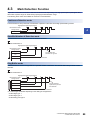
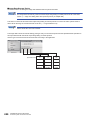
In the positioning dedicated signals, "n" in "M3200+20n", etc. indicates a value corresponding to axis No. as shown in the
following table.
Axis No.
n
Axis No.
n
Axis No.
n
Axis No.
n
1
0
9
8
17
16
25
24
2
1
10
9
18
17
26
25
3
2
11
10
19
18
27
26
4
3
12
11
20
19
28
27
5
4
13
12
21
20
29
28
6
5
14
13
22
21
30
29
7
6
15
14
23
22
31
30
8
7
16
15
24
23
32
31
• The range of axis No.1 to 16 (n=0 to 15) is valid in the R16MTCPU
• Calculate as follows for the device No. corresponding to each axis.
Ex.
For axis No. 32
M3200+20n (Stop command) = M3200 + 20 31 = M3820
M3215+20n (Servo OFF command) = M3215+20 31 = M3835
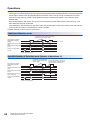
In the positioning dedicated signals, "n" in "M10440+10n", etc. of the "Synchronous encoder axis status", "Synchronous
encoder axis command signal", "Synchronous encoder axis monitor device" and "Synchronous encoder axis control device"
indicates a value corresponding to synchronous encoder axis No. as shown in the following table.
Synchronous encoder axis No.
n
Synchronous encoder axis No.
n
Synchronous encoder axis No.
1
0
5
4
9
8
2
1
6
5
10
9
3
2
7
6
11
10
4
3
8
7
12
11
• Calculate as follows for the device No. corresponding to each synchronous encoder.
Ex.
For synchronous encoder axis No.12
M10440+10n ([St.320] Synchronous encoder axis setting valid flag) = M10440 + 10 11 = M10550
D13240+20n ([Md.320] Synchronous encoder axis current value) = D13240 + 20 11 = D13460
18
n
1
1.1
MULTIPLE CPU SYSTEM
1
Multiple CPU System
Overview
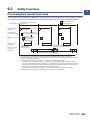
What is Multiple CPU system?
A Multiple CPU system is a system in which more than one PLC CPU module and Motion CPU module (up to 4 modules) are
mounted on several main base unit in order to control the I/O modules and intelligent function modules. Each Motion CPU
controls the servo amplifiers connected by SSCNET cable.
System configuration based on load distribution
• By distributing such tasks as servo control, machine control and information control among multiple processors, the flexible
system configuration can be realized.
• You can increase the number of control axes by using a multiple Motion CPU modules. It is possible to control up to 96
axes by using the three CPU modules (R32MTCPU).
• Overall system responsiveness is improved by distributing the high-load processing over several CPU modules.
Communication between CPUs in the Multiple CPU system
• Since device data of other CPUs can be automatically read by the Multiple CPU refresh function, the self CPU can also use
device data of other CPUs as those of self CPU.
• Motion dedicated PLC instructions can be used to access device data from the PLC CPU to Motion CPU and start Motion
SFC program.
1 MULTIPLE CPU SYSTEM
1.1 Multiple CPU System
19
Restrictions on Multiple CPU systems using Motion CPUs
Refer to the following for details on the Multiple CPU system concept (system configuration such as CPU module installation
positions, CPU Nos., I/O No. allocation etc.).
MELSEC iQ-R Series Module Configuration Manual
This section describes restrictions when using Motion CPUs.
CPU module installation position
Motion CPUs can only be used with the Multiple CPU system.
Motion CPU modules cannot be installed in CPU slots.
Controllable modules
■MELSEC iQ-R series modules
The following modules can be controlled with a Motion CPU. Modules other than those below cannot be controlled with a
Motion CPU.
Module
Input module
Model
RX10
RX40C7
RX41C4
RX42C4
RX40PC6H
RX40NC6H
Output module
RY10R2
RY40NT5P
RY41NT2P
RY42NT2P
RY40PT5P
RY41PT1P
RY42PT1P
Input/output composite module
Analog input module
RH42C4NT2P
R60AD4
R60ADI8
R60ADV8
R60AD8-G
R60AD16-G
Analog output module
R60DA4
R60DAI8
R60DAV8
R60DA8-G
R60DA16-G
High-speed counter module
RD62D2
RD62P2
RD62P2E
Temperature input module
RD60TD8-G
RD60RD8-G
■MELSEC Q series modules
MELSEC Q series modules cannot be controlled with the Motion CPU. If the Motion CPU is specified as the MELSEC Q
series module control CPU, a moderate error (error code: 2020H) is detected when turning ON the Multiple CPU system
power supply, and the module cannot be accessed.
20
1 MULTIPLE CPU SYSTEM
1.1 Multiple CPU System
Module access range from non-controlling CPU
1
• Access to MELSEC Q series modules controlled by other CPU is not possible from Motion CPU. (I/O reading from outside
the group is also not performed.)
• Module access devices (U\G) can be read. An error (error code differs for each function) is output when attempting to
write.
• X/Y devices for modules controlled by another CPU can be refreshed to a Motion X/Y with the I/O settings for outside the
group. However, I/O reading from outside the group is not performed for modules controlled by other CPUs that apply to
inter-module synchronization.
1 MULTIPLE CPU SYSTEM
1.1 Multiple CPU System
21
Module control with Motion CPUs
The settings required to control modules with Motion CPUs are as follows.
System configuration settings
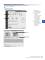
The system configuration for Multiple CPU systems and common parameters is set in the GX Works3 [Module Configuration]
and [System Parameter].
With Motion CPUs, parameters set at GX Works3 are read by MT Developer2, and therefore the system configuration and
common parameters are not set at MT Developer2. If setting the system configuration and common parameters, always do so
with GX Works3.
Furthermore, module parameters for modules set in the system configuration are set at GX Works3, however, module
parameters for modules for which a Motion CPU has been set as the control CPU cannot be set at GX Works3.
Settings for modules controlled by Motion CPUs are specified at the MT Developer2 [Module Configuration List].
For modules used with "High-precision" high-speed input request signals, set the "Synchronization Setting
within the Modules" to "Use" in GX Works3, and set the fixed scan interval setting to "0.444ms" or greater.
Please note that "Synchronization Setting within the Modules" can be used for modules with 32 or less input/
output points.
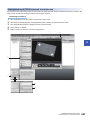
System configuration setting method
■GX Works3 settings
Set the following parameters at GX Works3.
• Module configuration
• System parameter(I/O assignment setting, Multiple CPU setting, Synchronization setting)
• Set the Motion CPU as the module control CPU in "Control PLC Settings" in [I/O Assignment Setting].
■MT Developer2 settings
• Read the parameters set at GX Works3 using MT Developer2 [System Parameter Diversion].
• Press the "Detailed" button at [R Series Common Parameters] [Module Configuration List] "Setting item" in MT
Developer2, and then set the parameters for the module for which a Motion CPU set has been set as the control CPU in the
module detailed settings that appear.
22
1 MULTIPLE CPU SYSTEM
1.1 Multiple CPU System
Module individual settings
1
The setting items for modules for which a Motion CPU has been set as the control CPU are shown below.
Module
Setting range*1
Item
Input module
Default value
Input/interrupt operation selection
Input/interrupt
Input
Interrupt condition setting
Leading edge/Trailing edge/Leading edge/trailing edge
Interrupt pointer
I0 to I15
Input response time setting
20s/50s/0.1ms/0.2ms/0.4ms/0.6ms/1ms/5ms/10ms/
20ms/70ms
*2
Output module
Error-time output mode setting
Clear/Maintain
Clear
I/O module
Input
Input/interrupt
Input
Interrupt condition setting
Leading edge/Trailing edge/Leading edge/trailing edge
Interrupt pointer
I0 to I15
Input response time setting
0.1ms/0.2ms/0.4ms/0.6ms/1ms/5ms/10ms/20ms/70ms
10ms
Error-time output mode
setting
Clear/Maintain
Clear
Pulses input mode
1 phase 1 time/1 phase 2 times/CW/CCW/
2 phase 1 time/2 phase 2 times/2 phase 4 times
1 phase 1 time
Counter speed setting
10kpps/100kpps/200kpps/500kpps/1Mpps/2Mpps/4Mpps/
8Mpps
10kpps
Output
High-speed counter
module
Analog input module
Analog output module
Temperature input
module
*1
*2
*3
Input/interrupt
operation selection
Counter type
Linear counter/Ring counter
Linear counter
Counter operation mode
Pulses counter mode/Pulses measure mode/PWM output
mode
Pulses counter mode
Function input response time setting
Response time 0ms/Response time 0.1ms/
Response time 1ms/Response time 10ms
Response time 0.1ms
Preset input response time setting
Response time 0ms/Response time 0.1ms/
Response time 1ms/Response time 10ms
Response time 0.1ms
Error-time output mode setting
Clear/Maintain
Clear
Input range setting
4 to 20mA/0 to 20mA/1 to 5V/0 to 5V/-10V to 10V/
0 to 10V/4 to 20mA (Extend)/1 to 5V (Extend)/
User range setting
*2
Operation mode setting
Normal mode(A/D conversion)/Offset/gain setting mode
Normal mode(A/D
conversion)
Output range setting
4 to 20mA/0 to 20mA/1 to 5V/0 to 5V/-10V to 10V/-12V to
12V/4 to 20mA (Extend)/1 to 5V (Extend)/User range
setting (Voltage)/User range setting (Current)/User range
setting 3/User range setting 2/User range setting 1
*2
Operation mode setting
Normal mode(A/D conversion)/Offset/gain setting mode
Normal mode(A/D
conversion)
Analog output HOLD/CLEAR setting
CLEAR/HOLD
CLEAR
Resistance temperature detector
type setting*3
Pt100(-200 to 850)/Pt100(-20 to 120)/JPt100(-180 to
600)/JPt100(-20 to 120)/Pt100(0 to 200)/JPt100(0 to
200)/Ni100(-60 to 250)/Pt50(-200 to 650)
Pt100(-200 to 850)
Thermocouple type setting*3
K thermocouple/E thermocouple/J thermocouple/T
thermocouple/B thermocouple/R thermocouple/S
thermocouple/N thermocouple
K thermocouple
Offset/gain setting
Factory setting/User range setting
Factory setting
Operation mode setting
Normal mode (temperature conversion processing)/Offset/
gain setting mode
Normal mode (temperature
conversion processing)
Items that can be set will differ depending on the module used.
Default values will differ depending on the module used.
Items that can be set will differ depending on the temperature input module used.
Set those module settings not shown above in the buffer memory for each module.
1 MULTIPLE CPU SYSTEM
1.1 Multiple CPU System
23
1.2
Setting Operation for Multiple CPU System
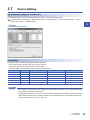
This section describes all operation settings for Multiple CPU systems. Specify all operation settings for Multiple CPU systems
in the GX Works3 [System Parameter]. Refer to the following for details on all operation settings.
MELSEC iQ-R CPU Module User's Manual (Application)
Setting operation for CPU module stop error
If a moderate or major error occurs at any of the CPUs, set whether to stop or continue operation for all CPUs.
Set the stopping mode for the CPU to be stopped in [System Parameter] [Multiple CPU Setting] "Multiple CPU Setting"
"Operation Mode Setting" "Stop Setting" in GX Works3.
Multiple CPU synchronous startup setting
Multiple CPU synchronous startup function synchronizes the startups of CPU No.1 to CPU No.4. (It takes about ten seconds
to startup for Motion CPU. After startup, each CPU requires time for initializing.)
Since this function monitors the startup of each CPU module, when other CPU is accessed by a user program, an interlock
program which checks the CPU module startup is unnecessary. With the Multiple CPU synchronous startup function, the
startup is synchronized with the slowest CPU module to startup; therefore, the system startup may be slow.
Multiple CPU synchronous startup function is for accessing each CPU module in a Multiple CPU system
without needing an interlock. This function is not for starting an operation simultaneously among CPU
modules after startup.
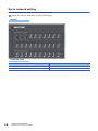
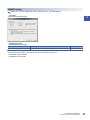
Multiple CPU synchronous startup setting
Set "Synchronize" in the Multiple CPU synchronous startup setting of the CPU in [System Parameter] [Multiple CPU
Setting] "Multiple CPU Setting" "Operation Mode Setting" "Synchronous Startup Setting"
When not performing Multiple CPU synchronous startup (each CPU startup without synchronization), startup of each CPU
module can be confirmed by using special relays SM220 to SM223 (CPU No.1 to 4 READY complete flag).
Clock synchronization between Multiple CPU
Motion CPU clock data is synchronized with the clock of CPU No. 1.
The clock data used for synchronization in a Multiple CPU system can be edited.(Page 102 Clock Function)
24
1 MULTIPLE CPU SYSTEM
1.2 Setting Operation for Multiple CPU System
1.3
Data Communication Between CPU Modules in the
Multiple CPU System
1
Data transfer is performed between CPU modules in the Multiple CPU system. Data can be written and read between CPUs
through communication by refreshing or by direct access. Data communication methods are shown below.
Refer to the following for details on data communication between CPU modules (data communication via CPU buffer memory/
fixed scan communication area).
MELSEC iQ-R CPU Module User's Manual (Application)
Communication
method
Application
Details
Data communication via
CPU buffer memory
Use to transfer data based on the timing
of the respective CPU modules.
CPU modules transmitting data write to the self CPU buffer memory. CPU modules
receiving data read from the self CPU buffer memory of the CPU module (other
CPU) from which the data was transmitted.
Data communication via
fixed scan communication
area
Use to transfer data based on the timing
between CPU modules.
CPU modules transmitting data write to the self CPU fixed scan communication
area (transmission area). CPU modules receiving data read from the self CPU fixed
scan communication area (receipt area) of the CPU module to which the data was
transmitted.
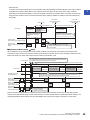
Used memory
Data communication between CPU modules uses the CPU buffer memory.
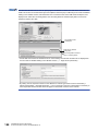
CPU buffer memory configuration
The CPU buffer memory configuration is shown below.
CPU buffer memory
0
to
2047
2048
System area
User setting area
to
Occupies the points for refresh(END) only.
When refresh(END) is not used, this can be
used as user setting area.
Refresh(END) area
524287
524288
to
999999
1000000
to
System area
User setting area
2097151
CPU buffer memory
(Fixed scan communication area)
0
to
(Fixed scan communication
area setting points - 1)
User setting area
Refresh(I45 executing)
area
Occupies the points for refresh(I45 executing) only.
When refresh(I45 executing) is not used, this
can be used as user setting area.
1 MULTIPLE CPU SYSTEM
1.3 Data Communication Between CPU Modules in the Multiple CPU System
25
Memory
Communication method
Details
Area size
CPU buffer memory
Communication by direct access
Data reading and writing is performed for the self CPU or
other CPU area.
PLC CPU: 512k words
Motion CPU: 2M words
Refresh area
Communication by refresh
Data communication is performed by refreshing at END
processing.
Fixed scan
communication
area*1
Communication by direct access
Data reading and writing is performed for the self CPU fixed
scan communication area, and self CPU and other CPU data
transfer is performed in fixed scan communication cycles.
Refresh area
Communication by refresh
Refresh is performed in fixed scan communication cycles.
*1
Changes can be made within an
overall range of 0 to 24k words. The
transmission area per module can
be set in the 0 to 12k word range.
To transfer data using the fixed scan communication area, specify fixed scan communication area settings at GX Works3. Refer to the
following for details on fixed scan communication area settings.
MELSEC iQ-R CPU Module User's Manual (Application)
• The system area is determined by the allocation in the system. Use the user area for communicating user
data.
• The refresh (END, I45 executing) area is used with the Multiple CPU refresh. Do not directly change this
area with a program.
Assurance for data communicated between Multiple CPUs
■Assurance of data sent between CPUs
Due to the timing of data sent from the self CPU and automatic refresh in any of the other CPUs, old data and new data may
become mixed (data separation).
The following shows the methods for avoiding data separation at communications by refresh.
• Data consistency for 32 bit data
Transfer data with refresh method is in units of 32 bits. Since refresh is set in units of 32 bits, 32-bit data does not separate.
For word data, 2 words data can be prevented from separating by using an even number to set the first number of each
device in refresh setting.
• Data consistency for 64-bit data
By setting the first number for the device set by refreshing to a multiple of 4, 64-bit data separation can be prevented.
• Data consistency for data exceeding 64 bits
In refresh method, data is read in descending order of the setting number in refresh setting parameter. Transfer data
separation can be avoided by using a transfer number lower than the transfer data as an interlock device.
26
1 MULTIPLE CPU SYSTEM
1.3 Data Communication Between CPU Modules in the Multiple CPU System
Data communication by refreshing at Motion CPUs
1
This section describes data communication by refreshing at Motion CPUs.
Refresh timing
The refresh timing at Motion CPUs differs from that for PLC CPUs. The refresh types and refresh timing are as follows.
Refresh type
MELSEC iQ-R series
Refresh (END)
Memory used
Refresh timing
PLC CPU side
Motion CPU side
CPU buffer memory
At END processing
Main cycle
Operation cycle and main cycle*2
Refresh (Q compatibility
high-speed refresh)*1
Refresh (I45 executing)
MELSEC Q series
(iQ Platform compatible)
*1
*2
*3
Fixed scan
communication area
Automatic refresh
When executing Multiple CPU
synchronous interrupt program (I45)
The longer of the operation cycle or
fixed scan communication cycle*3
At END processing
Main cycle
High-speed refresh
The longer of the operation cycle or
0.888ms and main cycle*2
This is an interchangeable setting equivalent to the MELSEC Q series "High-speed refresh" setting.
The order of processing inside the Motion CPU is as follows.
"Motion SFC event task Receipt refresh Motion operation Transmission refresh"
The order of processing inside the Motion CPU is as follows.
"Receipt refresh Motion SFC event task Motion operation Transmission refresh".
Furthermore, if the operation cycle is shorter than the fixed scan communication cycle, receipt refresh and transmission refresh are
performed only at the operation cycle immediately after the fixed scan communication cycle.
Fixed scan communication cycle
Motion CPU
fixed-cycle
processing
Receipt refresh
Transmission refresh
Motion operation cycle
Fixed scan communication
data transmission section
If using refresh (fixed scan communication), it is recommended that fixed scan communication cycles and
Motion operation cycles be aligned.
1 MULTIPLE CPU SYSTEM
1.3 Data Communication Between CPU Modules in the Multiple CPU System
27
Multiple CPU refresh setting
Setting for communicating by refresh.
In the refresh settings, up to 32 setting ranges (refresh (END) and refresh (I45 executing)) can be set for each CPU module.
[R Series Common Parameter] [System Parameter] [Multiple CPU Setting] "Communication Setting between
CPU" "Refresh (END) Setting" or "Refresh (I45 executing) Setting" "Detailed Setting"
Window
Displayed items
Item
Setting description
Setting range
Restriction
Data size
consistency
check
Refresh timing
Select "Detailed setting" based on the timing
at which data communication by refresh is
executed.
Refresh (END) setting/Refresh
(I45 executing)
Fixed-cycle refresh cannot be set if
fixed scan communication is invalid.
CPU selection
Select the CPU module for editing of the
CPU specific send range setting.
CPU No.1 to No.4
CPU No. which exceeds the number of
CPU modules cannot be selected.
Setting No.
The setting No. for transmission of each
CPU module is displayed. Automatic refresh
is executed between devices set to the
same setting No. for all CPUs that constitute
the Multiple CPU system.
1 to 32
Points
Set the number of points for data
communication.
Range: Refer to device list for
usable ranges.
(Page 66 Device
List)
Unit: 2 [points]
• Setting which exceeds the number of
points of the self CPU send area
allocated to each CPU module (CPU
specific send range) cannot be set.
• Bit device can be specified in units of
32 points (2 words) only.
Provided
Start
Specifies the device which performs the data
communication (refresh). Specifies the
device sent by the self CPU when the "Send
source CPU selection" is the self CPU, and
specifies the device received by the self
CPU when the CPU specific send range
setting is the other CPU.
Usable device ( X, Y, M, B, D,
W, #)*1
• Bit device can be specified in units of
16 points (1 word) only.
• Device number cannot be duplicated.
None
*1
28
Set "blank" when automatic refresh is not executed.
1 MULTIPLE CPU SYSTEM
1.3 Data Communication Between CPU Modules in the Multiple CPU System
Parameters set at GX Works3 are read at MT Developer2, and therefore there is no need to specify the
1
refresh (END) and refresh (I45 executing) settings, however, they should be set in the following cases.
• When a Motion register (#) is set to the transmitting device.
• When the Q compatibility high-speed refresh setting is used.
If specifying the Refresh (I45 executing) setting, specify the following settings in the GX Works3 [System
Parameter] [Multiple CPU Setting] "Communication setting between CPU".
Refer to the following for details on settings.
MELSEC iQ-R CPU Module User's Manual (Application)
• Set the "Fixed scan communication function" to "Use".
• Set the send area range for each CPU in the "Fixed scan communication area setting".
• Set the fixed scan interval setting of fixed scan communication (0.222ms/0.444ms/0.888ms/1.777ms/
3.555ms/7.111ms) in "Fixed scan communication settings".
Refresh processing performance is improved by setting the first device beginning with a 2-word unit or 4-word
unit.
■Operation example of refresh (END) that uses CPU buffer memory
A refresh (END) operation example using the CPU buffer memory is shown below.
CPU No.1
CPU No.2
CPU buffer memory
CPU buffer memory
Refresh area
Read by main cycle
of CPU No.2
Write by END process
of CPU No.1
Write by main cycle
of CPU No.2
Device
Device
B0 to B1F (CPU No.1)
B20 to B3F (CPU No.2)
Refresh area
B0 to B1F (CPU No.1)
Read by END process
of CPU No.1
B20 to B3F (CPU No.2)
■Refresh (I45 executing) operation example using fixed scan communication area
A refresh (I45 executing) operation example using the fixed scan communication area is shown below.
CPU No.1
CPU No.2
CPU buffer memory
CPU buffer memory
CPU No.1 fixed scan
communication area
Send to CPU No.2
Refresh area
CPU No.2 fixed scan
communication area
Refresh area
Write to refresh area
CPU No.1 fixed scan
communication area
Refresh area
Send to CPU No.1
CPU No.2 fixed scan
communication area
Refresh area
Write to refresh area
Read from refresh area
Read from refresh area
Device
Device
B0 to B1F (CPU No.1)
B0 to B1F (CPU No.1)
B20 to B3F (CPU No.2)
B20 to B3F (CPU No.2)
Refresh before and after I45 process
Refresh at the longer cycle of operation
cycle or fixed scan communication cycle
1 MULTIPLE CPU SYSTEM
1.3 Data Communication Between CPU Modules in the Multiple CPU System
29
■Application example of refresh setting (I45 executing)
Refresh setting (I45 executing) is used as in the following applications.
• Read the data such as the real current value and synchronous encoder current value with PLC CPU at high speed.
• Exchange the FIN waiting signal at high speed.
Multiple CPU refresh setting (Q compatibility high-speed refresh setting)
With self Motion CPUs, data between Motion CPU internal devices and the CPU buffer memory is updated every operation
cycle in the settings of devices for which refresh (at END) is set.
[R Series Common Parameter] [System Parameter] [Multiple CPU Setting] "Fixed Scan Communication Area
Setting" "Refresh (END) Setting" "Detailed Setting" "Q Compatibility High-speed Refresh Setting"
Window
Displayed items
Classification
Item
Description
Setting/display
value
Display
Setting
No.
Setting No. which executes high speed refresh is
displayed.
1 to 128
(Up to 128)
CPU
CPU No. set in the refresh (END) setting is
automatically displayed by setting devices.
• Self CPU
Refresh from the internal device of Motion CPU to
CPU buffer memory.
• Other CPU
Refresh from the CPU buffer memory to internal
device of Motion CPU.
CPU No. 1 to No.4
Device
setting
Set the device No. of Motion CPU to execute the high
speed refreshes.
Usable device:
D, W, #, M, X, Y, B
Points
Set the number of points to refresh data of each data
in word unit.
Sets the total of all CPUs to 256 points or lower.
*: Refresh is not executed when not set.
Range: 2 to 256
[points]
Unit: 2 points*1
Operation cycle (fixed)
User setting
Refresh
cycle
*1
30
Point in word unit.
1 MULTIPLE CPU SYSTEM
1.3 Data Communication Between CPU Modules in the Multiple CPU System
Restriction
• The start device number must be a multiple of
16 for the bit device.
• Cannot set a device not set also in the refresh
(END) setting.
• No. of "start device+number of points" cannot
exceed setting range of each setting No. in
refresh (END) setting.
• Cannot overlap the device No. between
setting No..
This refresh method is a setting for compatibility with the Q series Motion CPU with the purpose of making the
1
data refresh timing equivalent to that of "Multiple CPU high speed refresh" of the Q series Motion CPU.
When configuring a new system, we recommend using refresh (I45 executing) for communication of data that
is synchronized with the control of the Motion CPU.
■Operation example of Multiple CPU refresh setting (Q compatibility high-speed refresh
setting)
The operation example of Multiple CPU refresh setting (Q compatibility high-speed refresh setting) is shown below.
CPU No.1
CPU No.2
CPU buffer memory
Refresh area
CPU buffer memory
Read by main cycle or
operation cycle of
CPU No.2
Refresh area
Write by main
cycle or operation
cycle of CPU No.2
Write by END process
of CPU No.1
Device
Device
B0 to B1F (CPU No.1)
B0 to B1F (CPU No.1)
B20 to B3F (CPU No.2)
Read by END process
of CPU No.1
B20 to B3F (CPU No.2)
1 MULTIPLE CPU SYSTEM
1.3 Data Communication Between CPU Modules in the Multiple CPU System
31
Fixed scan data transmission section over check
A check is performed to verify whether Motion CPU fixed-cycle processing (Motion SFC event tasks, motion operations, etc.)
is completed by the data transmission section of the CPU fixed scan communication.
A check can be carried out to detect whether fixed scan transmission data separation has occurred. "Detect/Not detected"
and "Stop/Continue" can be selected in the "RAS settings" (refer to Page 48 CPU parameter).
Fixed scan communication cycle
Fixed scan communication cycle
Motion operation time
Motion CPU
fixed-cycle
processing
Receipt
refresh
Motion operation time
Operation Transmission
cycle
refresh
Fixed scan
Input refresh
transmission
section
OK (the send data can be seen
from other CPU in next cycle)
Operation cycle
Output
refresh
Fixed scan
transmission
section
NG (the send data cannot be seen from
other CPU in the next cycle because data
write was not completed by the beginning
of the transmission section)
Checks are performed as follows depending on the relationship between the motion operation cycle and fixed scan
communication cycle.
When motion operation cycle < fixed scan communication cycle
A check is performed only when an operation cycle over condition is detected, and not performed otherwise.
When motion operation cycle = fixed scan communication cycle
A check is performed every cycle.
When motion operation cycle > fixed scan communication cycle
A check is performed only at the fixed scan communication section immediately before the motion operation cycle. No check
is performed part of the way into a fixed scan communication section during a motion operation cycle, thus if a cycle shorter
than the motion operation cycle is referenced from another CPU, separation may occur even if no error occurs when
performing this check.
Special relay/special register
The special relay and special register relating to the fixed scan data communication section excess check are shown below.
Refer to the following for details on special relays and special registers.
• Special relay(Page 295 Special Relays)
• Special register(Page 300 Special Registers)
32
Device
Number
Name
Special relay
SM484
Fixed scan data transmission section over
Special register
SD484
Fixed scan data transmission section over count
1 MULTIPLE CPU SYSTEM
1.3 Data Communication Between CPU Modules in the Multiple CPU System
Inter-module synchronization function
1
Inter-module synchronization function overview
• By using the inter-module synchronization function, control timing can be synchronized across Motion CPUs, I/O modules,
and intelligent function modules. By enabling inter-module synchronization for modules controlled by a Motion CPU, motion
control and synchronized I/O control are possible.
• With the inter-module synchronization function, each module executes a "Inter-module synchronization interrupt program"
to perform fixed-cycle control. At the Motion CPU, overall Motion CPU fixed-cycle processing (Motion SFC fixed-cycle
event tasks, motion operation processing, etc.) corresponds to the inter-module synchronization interrupt program.
• By enabling the inter-module synchronization function between Multiple CPUs, the execution timing for self CPU Motion
CPU fixed-cycle processing and other CPU inter-module synchronization interrupt programs (PLC CPU 144 interrupt
program, Motion CPU fixed-cycle processing) can be synchronized.
• Set the inter-module synchronization function in the following cases.
• When using I/O module signals as high-speed input request signals
• When using a synchronous encoder via a high-speed counter module (By enabling inter-module synchronization, variations between synchronous encoder
input value operation cycles are reduced.)
Refer to the following for details on the overall system inter-module synchronization function, including PLC
CPUs and network modules.
MELSEC iQ-R Inter-Module Synchronization Function Reference Manual
Inter-module synchronization setting
Set the inter-module synchronization settings in [System Parameter] [Synchronization Setting within the Modules]
"Synchronization Setting within the Modules" of GX Works3. Inter-module synchronization settings must be consistent across
the Multiple CPU system.
1 MULTIPLE CPU SYSTEM
1.3 Data Communication Between CPU Modules in the Multiple CPU System
33
If setting inter-module synchronization settings at the Motion CPU, set as follows.
Operating procedure
1.
Set "Use inter-module synchronization function in
system" to "Use".
2.
Set "Synchronize" from the setting of the selected
synchronization target module displayed in "Select the
synchronous target unit", for the module to be
synchronized.
3.
Set the "Inter-module synchronization target module
selection" as follows.
• Set "0.05ms unit setting" to "Not set".
• Set the following fixed scan interval compatible with the
Motion CPU in "Fixed scan interval setting (not set by
0.05ms)".
(0.222ms, 0.444ms, 0.888ms, 1.777ms, 3.555ms,
7.111ms)*1
*1
If a fixed scan interval other than the above that is not
compatible with the Motion CPU is set, a moderate error (error
code: 2222H) occurs when the Multiple CPU system power
supply is turned ON.
The operating status of the inter-module synchronization function for each module can be checked with the GX Works3
system monitor function.
Inter-module synchronization target refresh settings
Refresh settings are not required for modules controlled by Motion CPUs. I/O (X/Y) refresh is performed for all modules
controlled by Motion CPU control. Also, perform read to and write from the module buffer memory by direct access with a
module access device (U\G).
34
1 MULTIPLE CPU SYSTEM
1.3 Data Communication Between CPU Modules in the Multiple CPU System
Inter-module synchronization control timing
1
■Timing of I/O refresh processing
When using the inter-module synchronization function, the timing of motion operation cycles with Motion CPUs is linked to
inter-module synchronization cycles. Refresh of inter-module synchronization target modules I/O (X/Y) is performed before
and after Motion CPU fixed-cycle processing (Motion SFC fixed-cycle event tasks, motion operation processing, etc.) The
processing timing is as follows.
Inter-module synchronization cycle
Motion operation time
Motion CPU
fixed-cycle
processing
External
equipment
Input
refresh
Input
External
Input
equipment
Operation
cycle*1
Output
refresh
Input
Output
Input
Output
Input module
(Internal buffer)
Output
External
equipment
Output module
(Internal buffer)
Input latch
*1
Output
Synchronized output
Motion SFC event task and Motion real-time task processing
Inter-module synchronization target module input (X) refresh is performed when starting Motion CPU fixed-cycle processing,
and output (Y) refresh is performed when Motion CPU fixed-cycle processing is complete. Perform read to and write from the
module buffer memory by direct access with a module access device (U\G). Depending on the module, a buffer memory is
available for inter-module synchronous control. Refer to the User's Manual of each module for details on module operation
relating to the inter-module synchronization function.
■When the inter-module synchronization cycle and motion operation cycle differ
The processing timing if the inter-module synchronization cycle and motion operation cycle differ is as follows.
• When inter-module synchronization cycle < motion operation cycle
: Input refresh
: Output refresh
: Actual input timing
: Actual output timing
Inter-module
synchronization cycle
Motion CPU fixed-cycle
processing
Example 1
Example 2
Example 3
Operation cycle over
Motion operation cycle
• The Y device content at the moment output refresh processing is executed is output at the inter-module synchronization cycle immediately after. (Example 1,
2)
• When the timing of the output refresh and inter-module synchronization cycle overlap, a discrepancy in the actual output timing may occur depending on the
module. (Example 2) Therefore, to align the actual output timing of all modules, ensure that the "inter-module synchronization cycle motion operation cycle".
• If the Motion CPU fixed-cycle processing time, including output refresh processing, does not end within the motion operation cycle, an operation cycle over is
detected. (Example 3)
1 MULTIPLE CPU SYSTEM
1.3 Data Communication Between CPU Modules in the Multiple CPU System
35
• When inter-module synchronization cycle > motion operation cycle
: Input refresh
: Output refresh
: Actual input timing
: Actual output timing
Inter-module synchronization cycle
Example 4
Example 5
Operation cycle over
Motion operation cycle
• Input refresh is performed when processing the first Motion CPU fixed cycle within the inter-module synchronization cycle. Output refresh is performed when
processing the last Motion CPU fixed cycle within the inter-module synchronization cycle. (Example 4)
• If the Motion CPU fixed-cycle processing time, including output refresh processing, does not end within the motion operation cycle, an operation cycle over is
detected. (Example 5)
CPU module operating status and refresh operation
The CPU module operating status when using the inter-module synchronization function and the I/O (X/Y) refresh operation
are shown below.
CPU operating status
Refresh
executed/not
executed
I/O (X/Y) refresh timing
RUN (including when continue error
occurs)
Refresh
Motion operation cycle*1
• Refresh OFF for Y.*2
• Refresh is not performed at such times as when the module
does not start up or refresh does not function due to a
parameter error, etc.
STOP (including when stop error
occurs due to moderate error)
STOP (when major error occurs)
Do not refresh
Test mode (including when continue
error occurs)
Refresh
Motion operation cycle*1
*1
*2
Remarks
Refresh is still performed if interrupt is prohibited with a Motion SFC DI instruction.
The Y immediately before going into STOP status is saved, and all devices are turned OFF. Not all modules are turned OFF if there are
modules with allocations as synchronous encoder/manual pulse generator inputs.
Inter-module synchronization processing time
When using the inter-module synchronization function with a Motion CPU, I/O refresh is performed when processing fixed
cycles in the Motion CPU, therefore processing time increases by the increased amount of motion operation time. The
following is a guideline for inter-module synchronization function processing time.
Inter-module synchronization function processing time = 5[s] + 0.7[s] Number of input points *1+3[s] Number of output
points *1
*1
Total number of I/O points (words) for modules that are part of inter-module synchronization and controlled by the Motion CPU
If an operation cycle over condition occurs, review the module subject to synchronization and the inter-module
synchronization cycle settings.
If not using the inter-module synchronization function, by accessing actual I/O (X/Y) at the Motion SFC fixedcycle event task, bus access occurs for each instruction, causing a drop in performance.
If using the inter-module synchronization function, an overhead occurs for the amount of processing time
mentioned above, and actual I/O (X/Y) are collectively refreshed, which can reduce motion operation time.
36
1 MULTIPLE CPU SYSTEM
1.3 Data Communication Between CPU Modules in the Multiple CPU System
Special relay/special register
1
The special relays and special register relating to the inter-module synchronization function are shown below. Refer to the
following for details on special relays and special registers.
• Special relay(Page 295 Special Relays)
• Special register(Page 300 Special Registers)
Device
Number
Name
Special relay
SM480
Motion CPU operation cycle over
Special register
SM488
Module synchronization error detection
SD480
Motion CPU operation cycle over counter No.
Inter-module synchronization function in Multiple CPU configuration
■Operating specifications
Refer to relationship between fixed scan communication and inter-module synchronization for the motion operation cycle
relationship when fixed scan communication and inter-module synchronization are combined. (Page 41 Relationship
between fixed scan communication and inter-module synchronization)
The data flow when fixed scan communication and the inter-module synchronization function are combined and
communicating with the PLC CPU is as follows.
• When the Multiple CPU synchronous interrupt function and inter-module synchronization function are combined (PLC CPU
Motion CPU)
Two inter-module synchronization cycles are required for data acquired by the PLC CPU by the time it reaches the Motion CPU via the CPU buffer memory
(fixed scan communication area). When synchronizing output between CPUs, use a function block for the inter-module synchronization function with a PLC
CPU, and program taking into account the difference in output timing (two cycles) between the PLC CPU control module and Motion CPU control module.
• When the Multiple CPU synchronous interrupt function and inter-module synchronization function are combined (Motion
CPU PLC CPU)
One inter-module synchronization cycle is required for data acquired by the Motion CPU by the time it reaches the PLC CPU via the CPU buffer memory
(fixed scan communication area). If synchronizing output between CPUs, adjust the number of Motion SFC fixed-cycle event task consecutive transitions for
the Motion CPU, and program taking into account the difference in output timing (one cycle) between the PLC CPU control module and Motion CPU control
module.
■Module access from other CPU
Even if the following settings are set in GX Works3, inputs (X) and outputs (Y) cannot be read from modules subject to the
inter-module synchronization function. Reading from the buffer memory is possible by direct access with a module access
device (U\G), FROM instruction, etc.
• When set to "import" at the [System Parameter] [Multiple CPU Setting] "Other PLC Control Module Setting" "I/O
Setting Outside Group".
■Aligning the inter-module synchronization function start timing at all CPUs, all stations
Specify the following settings in GX Works3.
• Set each module in [System Parameter] [Synchronization Setting within the Modules] "Select Synchronous Target
Unit between Unit" to "Synchronize".
• Set all CPUs in [System Parameter] [Multiple CPU Setting] "Operation Mode Setting" "Synchronous Startup
Setting" to "Synchronize".
1 MULTIPLE CPU SYSTEM
1.3 Data Communication Between CPU Modules in the Multiple CPU System
37
■Link between inter-module synchronization function and CPU fixed scan communication
When the following are set in GX Works3, CPU fixed scan communication operates based on the fixed scan interval set with
the inter-module synchronization function, enabling control with the timing of both inter-module synchronization function and
CPU fixed scan communication aligned.
• Set "Cooperate" in [System Parameter] [Multiple CPU Setting] "Communication Setting Between CPU" "Fixed
Scan Communication Function" "Fixed Scan Interval Setting of Fixed Scan Communication" "Fixed Scan
Communication Function and Inter-Module Synchronization Function".
If using both the fixed scan communication function and inter-module synchronization function, set "Fixed
Scan Communication Function and Inter-Module Synchronization Function" to "Cooperate". If set to "Not
cooperated", a moderate error (error code: 2222H) occurs, and the Motion CPU does not RUN.
Inter-module synchronization function operation when the CPU operating status
changes
■Operation at power supply ON, reset
• Normal startup (RUN)
If there are no setting errors in the parameters etc. after analysing inter-module synchronization function related settings
(system parameters, CPU parameters, module parameters) written to the Motion CPU when turning the Multiple CPU
system power supply ON or when cancelling a reset, the inter-module synchronization function operates.
• Abnormal stop (STOP)
When parameter inconsistencies between Multiple CPUs or network parameter setting errors, etc. occur, or if module
hardware errors have occurred when analysing inter-module synchronization function related settings (system parameters,
CPU parameters, module parameters) written to the Motion CPU when turning the Multiple CPU system power supply ON
or when cancelling a reset, the inter-module synchronization function does not operate, and a stop error occurs. When this
happens, I/O refresh is not performed.
■Operation at STOP (RUN STOP)
• Normal stop
I/O refresh continues even during a STOP condition. With a normal stop operation such as STOP, Motion CPU output is
turned OFF, and a stop command is issued to each module. Refer to the User's Manual for each module for details on
operation when the module stops normally.
If performing key operation, RUN to STOP is recognized
when CPU module END processing is performed.
Inter-module synchronization cycle
Scan
CPU module
END
RUN to STOP
Inter-module synchronization
cycle
As the module is in the STOP condition, the inter-module
synchronization interrupt program does not run
Inter-module synchronization cycle
Scan
Normal control
program
Synchronous Normal control
interrupt prgrm.
program
END
The execution of all programs, including inter-module
synchronous interrupt programs, is stopped with the
STOP operation.
Outut module
(Inter-module synchronization target)
Output module
(Not inter-module synchronization
target)
Output
Output
Hold/
Clear
Hold/
Clear
Output and deceleration stop are performed for all modules,
including the target module of inter-module synchronization,
when the STOP operation is peformed.
(Refresh is performed at END processing during STOP status)
38
1 MULTIPLE CPU SYSTEM
1.3 Data Communication Between CPU Modules in the Multiple CPU System
• Abnormal stop
If a Motion CPU major/moderate error occurs (including cases where settings ensure that Motion CPUs stop at a major/
1
moderate error at each module), Motion CPU output is turned OFF (there are also cases when output is retained
depending on the parameter settings), and a stop command is issued to the control module. I/O refresh continues even
during a STOP condition. Refer to the User's Manual for each module for details on operation when the module stops
abnormally.
Inter-module
synchronization timing
(first stop)
RUN to STOP
Inter-module synchronization cycle
CPU module
Motion operation/
Motion SFC
fixed-cycle event task
Motion SFC
normal task
Output module
(Not inter-module synchronization
target)
Inter-module synchronization cycle
Motion operation
If a moderate error occurs, motion
operation continues (deceleration stop)
Execution of the program is
stopped when a stop error
occurs.
Output module
(Inter-module synchronization target)
Inter-module
synchronization timing
(second stop)
Hold/
Clear
Output
Dec.
stop
Output
Output modules either hold or clear (stop)
external outputs depending on the specifications
for each module.
■Operation at RUN (STOP RUN)
When the Motion CPU is changed from STOP to RUN, the Motion CPU issues an inter-module synchronization start
command to each module at the next inter-module synchronization cycle after STOP to RUN, and begins execution of the
Motion SFC fixed-cycle event task at the next inter-module synchronization cycle.
STOP to RUN
The next operation is performed at the first inter-module synchronization cycle.
•An “Inter-module synchronization command” is issued to the control module.
•The Motion SFC fixed-cycle event task is not executed.
Inter-module synchronization
Inter-module synchronization cycle Inter-module synchronization cycle
cycle
Main cycle
Motion CPU
Motion operation
Motion SFC
normal task
Motion operation/
Motion SFC fixedcycle event task
Motion SFC
normal task
Motion operation
/Motion SFC fixedcycle event task
Motion SFC
normal task
ON
[St.1550] PCPU ready
complete (SM500)
Output module
(Inter-module
synchronization target)
OFF
The next operation is performed at the second inter-module synchronization cycle.
•Execution of the Motion SFC fixed cycle event task is started.
Hold/
Clear
Output
Output module
(Inter-module
synchronization target)
Output module
(Not inter-module
synchronization target)
Output
Input
Hold/
Clear
Output
Input
Output is resumed in
accordance with the
transition to the RUN status.
Please note that if system parameters related to the inter-module synchronization function are rewritten during STOP,
analysis is not performed at STOP to RUN, and therefore the module operates based on parameters before rewriting. The
changed parameters will be valid the next time the Multiple CPU system power supply is turned ON, or when reset.
1 MULTIPLE CPU SYSTEM
1.3 Data Communication Between CPU Modules in the Multiple CPU System
39
Error detection
The following error statuses are monitored at the Motion CPU.
■Execution time monitoring of the Motion CPU fixed-cycle processing
Regardless of whether the inter-module synchronization function is used, the Motion CPU fixed-cycle processing (intermodule synchronization I/O refresh, Motion SFC fixed-cycle event task, motion operation processing, etc.) execution time is
monitored. When Motion CPU fixed-cycle processing is not completed within the motion operation cycle, the number of times
that a Motion CPU fixed-cycle processing cycle error occurs is stored in "Motion CPU operation cycle over counter No.
(SD480)".
When "Over Execute Time (Operation Cycle Over)" in [CPU Parameter] "RAS Setting" "Error Detections Setting" is set
to "Detect", "Stop" or "Continue" can be selected for Motion CPU operation processing. When set to "Detect", a moderate
error (error code: 2600H) is output.
■Inter-module synchronization signal error monitor
Inter-module synchronization signal cycle errors are monitored, and a moderate error (error code: 2610H) occurs if there is an
error.
Motion CPU operation processing can bet set to "Stop" or "Continue" when a inter-module synchronization signal error occurs
with [CPU Parameter] "RAS Setting" "CPU Module Operation Setting at Error Detected".
When "Synchronous Interrupt Execution Interval Error (CPU module)" is set to "Continue", if the continuation
error is cancelled, the Motion CPU ERROR LED turns OFF but the error factor is not removed. Furthermore,
errors are not detected again even if a synchronous interrupt execution interval error reoccurs.
40
1 MULTIPLE CPU SYSTEM
1.3 Data Communication Between CPU Modules in the Multiple CPU System
Relationship between fixed scan communication and intermodule synchronization
1
If using fixed scan communication and inter-module synchronization between multiple CPUs, the relationship between motion
operations and Motion SFC event task (fixed-cycle tasks) is as follows.
Inter-module synchronization function
Fixed scan
communication
function
*2
Used
Motion CPU inherent cycle
Synchronization with inter-module
synchronization cycle*2
(timing example 2)
If the "Fixed scan communication function
and inter-module synchronization function"
setting is "Not cooperated".
Synchronization with fixed scan
communication cycle*2
(timing example 1)
Moderate error
(error code: 2222H)
If the "Fixed scan communication function
and inter-module synchronization function "
setting is "Cooperate".
Setting not possible with Engineering
Tool
Inter-module synchronization cycle
=synchronization with fixed scan
communication cycle*1
(timing example 3)
Not used
Used
*1
Not used*1
If inter-module synchronization function is set to not used, or if the Motion CPU is not the module subject to inter-module
synchronization.
If the motion operation cycle and fixed scan communication cycle, or the inter-module synchronization cycle differ, the start timing with
longer cycle is always synchronized with the start timing with shorter cycle.
If a cycle (other than 0.222ms, 0.444ms, 0.888ms, 1.777ms, 3.555ms, 7.111ms) not compatible with Motion
CPUs is set for a fixed scan communication cycle or inter-module synchronization cycle, a moderate error
(error code: 2222H) occurs when the Multiple CPU system power supply is turned ON.
Timing Example 1
Fixed scan communication
timing
Motion operation
Timing Example 2
Inter-module
synchronization timing
Motion operation
Timing Example 3
Fixed scan communication
timing
Inter-module
synchronization timing
Motion operation
1 MULTIPLE CPU SYSTEM
1.3 Data Communication Between CPU Modules in the Multiple CPU System
41
Control instruction from PLC CPU to Motion CPU
Control can be instructed from the PLC CPU to the Motion CPU using the Motion dedicated PLC instructions listed in the table
below.
Refer to the following for the details of each instruction. (Control may not be instructed from one Motion CPU to another
Motion CPU.)
MELSEC iQ-R Motion controller Programming Manual (Program Design)
Instruction name
Description
M(P).□
D(P).□
M(P).SFCS
D(P).SFCS
Start request of the Motion SFC program (Program No. may be specified.)
M(P).SVST
D(P).SVST
Start request of the specified servo program
M(P).SVSTD
D(P).SVSTD
Direct positioning start request
M(P).CHGA
D(P).CHGA
Current value change request of the specified axis
M(P).CHGAS
D(P).CHGAS
Current value change request of the specified command generation axis
M(P).CHGV
D(P).CHGV
Speed change request of the specified axis
M(P).CHGVS
D(P).CHGVS
Speed change request of the specified command generation axis
M(P).CHGT
D(P).CHGT
Torque control value change request of the specified axis
M(P).GINT
D(P).GINT
Execute request of an event task to the other CPU (Motion CPU)
M(P).DDWR
D(P).DDWR
Write device data of the self CPU (PLC CPU) to the device of other CPU (Motion CPU)
M(P).DDRD
D(P).DDRD
Read device data of other CPU (Motion CPU) to the device of self CPU (PLC CPU)
M(P).BITWR
D(P).BITWR
Write bit operation to the bit device of another Motion CPU
For example, by using the D(P).SFCS instruction of Motion dedicated PLC instruction, the Motion SFC of the Motion CPU can
be started from the PLC CPU.
Ex.
PLC CPU
Motion CPU
Start request
Motion SFC
D(P).SFCS instruction
42
1 MULTIPLE CPU SYSTEM
1.3 Data Communication Between CPU Modules in the Multiple CPU System
2
COMMON PARAMETERS
2.1
Parameters Used by the Motion CPU
2
The parameters used by the Motion CPU are as follows.
Parameter
Details
R series common parameters
Common parameters for R series CPU modules
Motion CPU common parameters
Common parameters for Motion CPU modules
Motion control parameters
Positioning control parameters and synchronous control parameters used by the Motion CPU for Motion control
A list of parameters used by the Motion CPU is shown below.
: Input, : Not input
Parameter item
R series
common
parameter
Motion CPU
common
parameter
Parameter input timing
Details
Reference
Set the R series CPU common
parameters for the base, slot, and module
settings and the Multiple CPU system
settings.
The system parameters for each CPU in
the Multiple CPU system must be
matched.
Page 46
System
parameter
At ON/reset of
Multiple CPU
system power
supply
At STOP to
RUN/test
mode request
System parameter
CPU parameter
Module parameter
Basic setting
Set the basic parameters of the Motion
system, such as operation cycle and the
external forced stop input.
Page 54
Basic setting
Servo network setting
Set the servo network type, the connected
servo amplifier, and the SSCNET/H
head module.
Page 56
Servo network
setting
Limit output data
Set the output device and watch data for
limit output.
Page 81
Limit output data
setting
High-speed input request signal
Set the high precision input request signal
used for advanced synchronous control or
mark detection.
Page 86
High-speed
input request
signal setting
Mark detection
Set the data for mark detection.
Page 91
Mark detection
setting
Manual pulse generator connection
setting
Set the data required for connecting the
manual pulse generator to the module.
Page 61
Manual pulse
generator
connection
setting
Vision system parameter
Set the parameters used for connecting
the vision system.
Page 195
Vision system
parameter
setting
Head module
Set the parameters used for connecting
the SSCNET/H head module.
Page 142
SSCNETIII/H
head module
parameters
Refresh (END/I45 executing) setting
Set the Multiple CPU refresh (main cycle/
operation cycle).
Page 28
Multiple CPU
refresh setting
Page 46
System
parameter
Page 48
CPU parameter
Page 52
Module
Parameter
2 COMMON PARAMETERS
2.1 Parameters Used by the Motion CPU
43
Parameter item
Motion
control
parameter
*1
*2
44
Details
Reference
Set the fixed data based on the
mechanical system, etc. of the controlled
axis.
*1
Set the data required for the home
position return.
JOG operation data
Set the data to perform the JOG
operation.
External signal
parameter
Set the external signals (upper stroke limit
(FLS), lower stroke limit (RLS), stop
(STOP), and proximity dog or speed/
position switching (DOG/CHANGE)) used
for each axis.
Expansion
parameter
Set when the following functions are used.
• Individual monitoring of positive and
negative direction torque limit values
• Change the acceleration/deceleration
time when changing speed
• When performing positioning control in
the absolute data method in degrees,
specify the positioning direction.
Speed-torque
control data
Set when the speed-torque control is
performed.
Optional data
monitor
Set the type of the monitored data and the
storage device when the servo amplifier
status, etc. is monitored.
Page 120
Optional data
monitor setting
Pressure control
data
Set when performing pressure control that
uses a profile.
*1
Override data
Set when using the override function.
Vibration
suppression
command filter data
Set when using vibration suppression
command filter function.
Servo parameter
Parameters for the servo amplifier are set
based on the specifications for the servo
amplifier and servo motor.
Parameter block
Set the data for acceleration/deceleration
control, etc. used for each positioning
processing.
Synchronous
control
parameter
Input axis parameter
Set the input axis used for advanced
synchronous control.
Synchronous
parameter
Set the synchronous parameters for the
output axis used for advanced
synchronous control.
Multiple CPU
advanced
synchronous control
setting
Set the master CPU and slave CPU for
performing Multiple CPU advanced
synchronous control.
Axis setting
parameter
Parameter input timing
At ON/reset of
Multiple CPU
system power
supply
At STOP to
RUN/test
mode request
Fixed parameter
Home position
return data
MELSEC iQ-R Motion Controller Programming Manual (Positioning Control)
MELSEC iQ-R Motion controller Programming Manual (Advanced Synchronous Control)
2 COMMON PARAMETERS
2.1 Parameters Used by the Motion CPU
*2
2.2
R Series Common Parameter
Set the MELSEC iQ-R series CPU module common parameters used at the Multiple CPU system for the R series common
parameters.
Common system
parameters
2
Motion CPU parameters
(set at MT Developer2)
PLC CPU parameters
(set at GX Works3)
Read by
MT Developer2
Individual
parameter
Common system
parameters
Individual
parameter
Power supply
Parameter write
RnCPU R32MT
CPU
2 COMMON PARAMETERS
2.2 R Series Common Parameter
45
System parameter
These parameters are used to set the Multiple CPU system module configuration and common system items. The system
parameters for each CPU in the Multiple CPU system must be matched. There is no need to set system parameters because
the parameters set in the GX Works3 "Module Configuration" or "System Parameter" are read by MT Developer2. However,
the "Refresh (END) setting", "Refresh (I45 executing) setting", and "Q compatibility high-speed refresh setting" in the
communication setting between CPU can be set based on the Motion CPU settings.
[R Series Common Parameter] [System Parameter] [Multiple CPU Setting] "Communication Setting between
CPU"
Window
Displayed items
Item
Multiple CPU
setting
Communication
setting between
CPU
Refresh (END)
setting*1
Refresh (I45 executing) setting
*1
46
Setting range
Default
Up to 32 settings for each CPU
No. of points: Refer to device list for allowable setting range.
(Page 66 Device List)
Start: Usable devices (X, Y, M, B, D, W, #)
No setting
Up to 32 settings for each CPU
No. of points: Refer to device list for allowable setting range.
(Page 66 Device List)
Start: Usable devices (X, Y, M, B, D, W, #)
No setting
Q compatibility high-speed refresh setting
Setting range
Default
Up to 128 settings for each CPU
No. of points: 2 to 256
Start: Usable devices (X, Y, M, B, D, W, #)
No setting
2 COMMON PARAMETERS
2.2 R Series Common Parameter
Communication setting between CPU
■Refresh (END) setting
Set up to 32 settings for refresh device per CPU. Refer to device list for the range of devices that can be set. (Page 66
Device List)
2
• Q compatibility high-speed refresh setting
Set refresh between CPUs with up to of 128 settings for the entire Multiple CPU system. Set 2 points (words) or more each,
and no more than 256 points in total. Refer to device list for the range of devices that can be set. (Page 66 Device List)
■Refresh (I45 executing)
Set up to 32 settings for refresh device per CPU. Refer to device list for the range of devices that can be set. (Page 66
Device List)
• Refer to Multiple CPU refresh setting for details on the Refresh (at END) and Refresh (I45 executing)
settings. (Page 28 Multiple CPU refresh setting, Page 30 Multiple CPU refresh setting (Q
compatibility high-speed refresh setting))
• If using the CPU fixed scan communication function set at GX Works3, or the inter-module synchronization
function, set the cycles that can be set at the Motion CPU (0.222ms/0.444ms/0.888ms/1.777ms/3.555ms/
7.111ms) for the fixed scan communication cycle or inter-module synchronization cycle. A moderate error
(error code: 2222H) occurs if a cycle other than the above cycles is set. Refer to relationship between fixed
scan communication and inter-module synchronization for details on the relationship with motion operation
cycle settings. (Page 41 Relationship between fixed scan communication and inter-module
synchronization)
2 COMMON PARAMETERS
2.2 R Series Common Parameter
47
CPU parameter
Set the operational details for the Motion CPU's functions. Also, regarding the overall system, settings for which verification
between CPUs is not necessary are also stored in these parameters.
[R Series Common Parameter] [Motion CPU Module] [CPU Parameter]
Window
Displayed items
Item
Name setting
Operation
related setting
Device related
setting
48
Setting range
Default value
Title setting
Up to 32 characters
No setting
Comment setting
Up to 256 characters
No setting
RUN contact
X0 to X2FFF
No setting
Output mode setting of STOP to RUN
Output the output (Y) status before STOP/Clear the output
(Y) (output is 1 scan later)
Output the output
(Y) status before
STOP
Module synchronous setting
Synchronize/Do not synchronize
Synchronize
Device points
Bit device (M, B, F)/Word device (D, W, #)
Page 73
Device Setting
Latch setting
Up to 32 settings
No setting
2 COMMON PARAMETERS
2.2 R Series Common Parameter
Item
RAS setting
Error detections
setting
CPU module
operation
setting at error
detected
I/O assignment
setting
Setting range
Default value
Module verify error
Detect/Not detected
Detect
Over execute
time of Motion
CPU fixed scan
process
Over execute
time (operation
cycle over)
Detect/Not detected
Not detected
Over fixed scan
data send
section
Detect/Not detected
Not detected
Stop/Continue
Stop
Instruction execution error module
I/O No. specification incorrect
Memory card access error
Stop/Continue
Stop
Module verify error
Stop/Continue
Stop
Over execute
time of Motion
CPU fixed scan
process
Over execute
time (operation
cycle over)
Stop/Continue
Stop
Over fixed scan
data send
section
Stop/Continue
Stop
Synchronous interrupt execution
interval error (CPU module)
Stop/Continue
Stop
Event history
setting
Save destination
SD memory card/Standard ROM
Standard ROM
Set save volume of per file
1 to 2048[k bytes]
128[k bytes]
CPU module
operation
setting at error
detected
Slot
0 to 63
Major: Stop, Moderate: Stop/Major: Stop, Moderate:
Continue/Major: Continue, Moderate: Continue
Major: Stop,
Moderate:
Continue
2
Name setting
■Title setting
Set the Motion CPU title (name, application). Up to 32 characters can be set.
■Comment setting
Set a comment for the title. Up to 256 characters can be set.
Operation related setting
■RUN contact
Set contacts used to control Motion CPU RUN signals. Only inputs (X) can be set.
Setting range
X0 to X2FFF
Refer to remote RUN/STOP for details on operation with RUN contacts. (Page 181 Remote RUN/STOP)
■Output mode setting of STOP to RUN
Set the output (Y) operation when switching from the STOP status to RUN status.
• Output the output (Y) status before STOP: If outputting the output (Y) status before STOP
• Clear the output (Y) (output 1 scan later) : If clearing the output (Y) status and outputting 1 scan later
■Module synchronous setting
Set whether or not to synchronize Motion CPU and intelligent function module startup.
• Synchronize: Synchronizes startup.
• Do not synchronize: Does not synchronize startup.
2 COMMON PARAMETERS
2.2 R Series Common Parameter
49
Device related setting
■Device points
Set the range for the number of points for each device.
Refer to device setting for details on the number of devices setting. (Page 73 Device Setting)
Refer to device list for the range of devices that can be set. (Page 66 Device List)
Settable devices
M, B, F, D, W, #
■Latch setting
Set the device (M, B, F, D, W, #) latch range. Up to 32 devices can be set for the latch (1) and latch (2) latch range. Refer to
latch function for details on the latch range setting. (Page 75 Latch Function)
Refer to device list for the range of devices that can be set. (Page 66 Device List)
RAS setting
■Error detections setting
• Module verify error
Set whether to "Detect" or "Not detect" module comparison errors in cases such as when a different module is detected
when the Multiple CPU system power supply is ON.
• Over execute time of Motion CPU fixed scan process
• Over execute time (operation cycle over)
Set whether to "Detect" or "Not detect" Motion CPU fixed-cycle processing execution time over conditions.
• Over fixed scan data send section
Set whether to "Detect" or "Not detect" errors if Motion CPU fixed-cycle processing is not complete by the time fixed scan data communication to another
CPU starts.
■CPU module operation setting at error detected
• Instruction execution error module I/O No. specification incorrect
Set whether to "Stop" or "Continue" Motion CPU processing if a module I/O No. specification incorrect error is detected.
• Memory card access error
Set whether to "Stop" or "Continue" Motion CPU processing if a memory card access error is detected.
• Module verify error
Set whether to "Stop" or "Continue" Motion CPU processing if a module comparison error is detected.
• Over execute time of Motion CPU fixed scan process
• Over execute time (operation cycle over)
Set whether to "Stop" or "Continue" Motion CPU processing if a Motion CPU fixed-cycle processing operation cycle over condition is detected.
• Over fixed scan data send section
Set whether to "Stop" or "Continue" Motion CPU processing if a Motion CPU fixed-cycle processing fixed scan data communication section over condition is
detected.
• Synchronous interrupt execution interval error (CPU module)
Set whether to "Stop" or "Continue" Motion CPU processing if the Motion CPU detects a synchronous signal error.
■Event history setting
• Save destination
Set the storage destination for event history files.
• SD memory card
• Standard ROM
• Set save volume of per file
Set the saving volume per event history file.
Setting range
1 to 2048[k bytes]
50
2 COMMON PARAMETERS
2.2 R Series Common Parameter
I/O assignment setting
■CPU module operation setting at error detected
Set the CPU module operation mode during error for slot 0 to slot 63.
• Major: Stop, Moderate: Stop
2
• Major: Stop, Moderate: Continue
• Major: Continue, Moderate: Continue
2 COMMON PARAMETERS
2.2 R Series Common Parameter
51
Module Parameter
Specify local node settings and security in order to communicate with external devices with the Motion CPU PERIPHERAL I/F.
[R Series Common Parameter] [Motion CPU Module] [Module Parameter]
Window
Displayed items
Item
Setting range
Default value
Local node
setting
IP address
setting
IP address
0.0.0.1 to 223.255.255.254
192.168.3.39
Subnet mask
0.0.0.1 to 255.255.255.254/blank
No setting
Default gateway
0.0.0.1 to 255.255.255.254/blank
No setting
Security
IP filter setting
IP filter use or not
Use/Not used
Not used
IP filter setting
Up to 32 settings
No setting
Disable direct connection to MELSOFT
Enable/Disable
Enable
Do not respond to search for CPU module on
network
Response (no check)/Not responded (check)
Response (no check)
Local node setting
■IP address setting
• IP address
Set the local node IP address.
• Subnet mask
Set the IP address in order to set which upper bit to use for the network address to identify the network.
• Default gateway
Set the IP address for the passing device (default gateway) used to access the network device to which the local node
belongs.
Security
■IP filter setting
Data set at GX Works3 is read by MT Developer2, and therefore there is no need to set the IP filter.
■Disable direct connection to MELSOFT
Set whether to "Enable" or "Disable" a direct connection (simple connection) with the Engineering Tool.
■Do not respond to search for CPU module on network
Set whether to "Respond" or "Not respond" to an Engineering Tool network CPU module search.
52
2 COMMON PARAMETERS
2.2 R Series Common Parameter
2.3
Motion CPU Common Parameter
The Motion CPU common parameters are used to specify Motion CPU basic settings, the servo network configuration, and all
auxiliary functions. A list of Motion CPU common parameter settings is shown in the table below.
Item
Basic
setting
Operation cycle
Forced stop
input setting
Setting range
Default value
Remark
0.222ms/0.444ms/0.888ms/1.777ms/
3.555ms/7.111ms/Default setting
Default setting
Set the operation cycle of motion
control.
Set the bit device to use for the
forced stop.
Instruction
Not used/Used
Not used
Device
Bit device
Not setting
File transmission setting during booting
Standard ROM write permission/read
protection/
Standard ROM write protection/read
protection/
Standard ROM write protection/read
permission/
Standard ROM write permission/read
protection/Boot operation file invalid
Standard ROM
write permission /
read protection
Set whether to permit/protect file
transmission at boot
SSCNET
setting
Communication type
SSCNET/H/SSCNET
SSCNET/H
Set the communication type for
every line.
Amplifier
setting
Amplifier
information
<Communication type "SSCNET/H" use>
MR-J4(W)-B(-RJ)/MR-J4-B-LL/
VC (Nikki Denso) /LJ72MS15
MR-J4(W)-B(-RJ)
Set the model name, axis No. and
other details for the servo
amplifiers.
<Communication type "SSCNET" use>
MR-J3(W)-B/MR-J3-B(S) Fully closed/MRJ3(W)-B Linear/MR-J3(W)-B DD motor/MRMT1200/FR-A700/FR-A700-NA/FR-A700EC/FR-A700-CHT/VC (Nikki Denso)
MR-J3(W)-B
Amplifier
operation
mode
<Communication type "SSCNET/H" use>
Standard/Fully closed/Linear/DD motor
Standard
Axis No.
R32MTCPU: Up to 2 lines, 32 axes
R16MTCPU: Up to 1 line, 16 axes
No setting
RIO axis
No.*1
<Communication type "SSCNET/H" use>
R32MTCPU: Up to 2 lines, 8 axes
R16MTCPU: Up to 1 line, 4 axes
No setting
Station
No.d
<Communication type "SSCNET/H" use>
1 to 64
No setting
Axis label/
RIO axis
label*1
Up to 32 characters
No setting
External synchronous
encoder input*2
Invalid/ABS/INC
Invalid
Input filter setting
Nothing/0.8ms/1.7ms/2.6ms/3.5ms
3.5ms
Allowable travel during
Power-Off
<Communication type "SSCNET" use>
0 to 8191 revolution
10
Limit output data
Set 1 to 64
No setting
Page 81 Limit output data
setting
High-speed input request signal
Set 1 to 64
No setting
Page 86 High-speed input
request signal setting
Servo
network
setting
Axis
information
Amplifier
model
Mark detection
Set 1 to 32
No setting
Page 91 Mark detection setting
Manual pulse generator connection setting
Set P1 to P3
No setting
Page 61 Manual pulse
generator connection setting
Vision system
parameter
Ethernet communication
line
Vision system No. 1 to 32
No setting
Page 195 Ethernet
Communication Line Setting
Vision program operation
Program No. 1 to 128
No setting
Page 198 Vision Program
Operation Setting
Set module 1 to 4 for each line.
R32MTCPU: 2 lines (Up to 8 modules)
R16MTCPU: 1 line (Up to 4 modules)
No setting
Page 142 Parameter setting of
SSCNETIII/H head module
Head module
*1
*2
2
This is the RIO-axis when "LJ72MS15" is selected for the amplifier model.
This can only be set when "MR-J4(W)-B(-RJ)" is selected for the amplifier model.
2 COMMON PARAMETERS
2.3 Motion CPU Common Parameter
53
Basic setting
The following explains each item to be set in basic setting.
[Motion CPU Common Parameter] [Basic setting]
Window
Displayed items
Item
Operation cycle
Forced stop input
setting
Setting range
Default value
0.222ms/0.444ms/0.888ms/1.777ms/3.555ms/7.111ms/Default setting
Default setting
Instruction
Not used/Used
Not used
Device
Bit device
No setting
Standard ROM write permission/read protection/
Standard ROM write protection/read protection/
Standard ROM write protection/read permission/
Standard ROM write permission/read permission/Boot operation file invalid
Standard ROM write
permission/read
protection
File transmission setting during
booting
Operation cycle
• Set the of motion operation cycle (cycles at which a position command is computed and sent to the servo amplifier).
• The default value is "Default Setting". The operation cycle is set according to the table below based on the number of axes
for servo amplifier set in the servo network setting.
Number of axes
Operation cycle setting
1 to 2 axes
0.222ms
3 to 8 axes
0.444ms
9 to 20 axes
0.888ms
21 to 32 axes
1.777ms
• If the duration of motion operation has exceeded the operation cycle, the "[St.1046] Operation cycle over flag (M2054)"
turns ON. (Page 243 Processing time monitor and check)
• The number of stations capable of connecting to the SSCNET(/H) 1 line is limited based on the motion operation cycle.
Refer to the following for details on restrictions based on the communication methods and operation cycles used.
MELSEC iQ-R Motion Controller User's Manual
Forced stop input setting
Set the bit device used for the forced stop to perform a forced stop for all servo amplifier axes together. Refer to device list for
the range of bit devices that can be set. (Page 66 Device List)
No default value has been set. The set bit device is designated as contact B and performs the following control in response to
ON/OFF of the device.
54
Bit device
Details
Bit device is turned OFF
Forced stop input is ON (forced stop)
Bit device is turned ON
Forced stop input is OFF (forced stop is released.)
2 COMMON PARAMETERS
2.3 Motion CPU Common Parameter
File transmission setting during booting
Set the operation for performing the file transmission at boot function.
Refer to file transmission at boot function for details of the file transmission at boot function. (Page 107 File Transmission
at Boot Function)
2
The file transmission at boot settings from the last time power supply was shutoff are valid when the power supply of the
Multiple CPU system is turned ON.
Setting
Details
Standard ROM write permission/read
protection
• Moving or copying to the standard ROM is permitted for files saved outside of the standard ROM.
• Moving or copying out of the standard ROM is protected for files saved in the standard ROM.
Standard ROM write protection/read
protection
• Moving or copying to the standard ROM is protected for files saved outside of the standard ROM.
• Moving or copying out of the standard ROM is protected for files saved in the standard ROM.
Standard ROM write protection/read
permission
• Moving or copying to the standard ROM is protected for files saved outside of the standard ROM.
• Moving or copying out of the standard ROM is permitted for files saved in the standard ROM.
Standard ROM write permission/read
protection
• Moving or copying to the standard ROM is permitted for files saved outside of the standard ROM.
• Moving or copying out of the standard ROM is permitted for files saved in the standard ROM.
Boot operation file invalid
File transmission at boot function cannot be used.
The file transmission at boot settings at the time of when Multiple CPU system power supply is turned ON are
stored in "Boot file transfer information (SD509)".
Refer to special registers for details on special registers. (Page 300 Special Registers)
2 COMMON PARAMETERS
2.3 Motion CPU Common Parameter
55
Servo network setting
The following explains each item to be set in servo network setting.
[Motion CPU Common Parameter] [Servo network setting]
Window
Displayed items
Item
56
Setting range
SSCNET setting
Page 57 SSCNET setting
Amplifier setting
Page 58 Amplifier setting
2 COMMON PARAMETERS
2.3 Motion CPU Common Parameter
SSCNET setting
[Motion CPU Common Parameter] [Servo network setting] [SSCNET Setting]
Window
2
Displayed items
Item
Setting range
Default value
Communication type
SSCNET/H/SSCNET
SSCNET/H
■Communication type
Set the communication type to communicate with the servo amplifier for every line.
• SSCNET/H: MR-J4(W)-B
• SSCNET: MR-J3(W)-B
2 COMMON PARAMETERS
2.3 Motion CPU Common Parameter
57
Amplifier setting
[Motion CPU Common Parameter] [Servo network setting] [Amplifier Setting]
Window
Displayed items
Item
Amplifier
information
Axis
information
Default value
<Communication type "SSCNET/H" use>
MR-J4(W)-B(-RJ)/MR-J4-B-LL/VC (Nikki Denso) /LJ72MS15
MR-J4(W)-B(-RJ)
<Communication type "SSCNET" use>
MR-J3(W)-B/MR-J3-B(S) Fully closed/MR-J3(W)-B Linear/MR-J3(W)-B DD motor/
MR-MT1200/FR-A700/FR-A700-NA/FR-A700-EC/FR-A700-CHT/VC (Nikki
Denso)
MR-J3(W)-B
Amplifier operation mode*1
<Communication type "SSCNET/H" use>
Standard/Fully closed/Linear/DD motor
Standard
Axis No.
R32MTCPU: Up to 2 lines, 32 axes
R16MTCPU: Up to 1 line, 16 axes
No setting
RIO axis No.*2
<Communication type "SSCNET/H" use>
R32MTCPU: Up to 2 lines, 8 axes
R16MTCPU: Up to 1 line, 4 axes
No setting
Station No.d
<Communication type "SSCNET/H" use>
1 to 64
No setting
Axis label/RIO axis label*2
Amplifier model
Up to 32 characters
No setting
External synchronous encoder input*1
Invalid/ABS/INC
Invalid
Input filter setting
Nothing/0.8ms/1.7ms/2.6ms/3.5ms
3.5ms
Allowable travel during Power-Off
<Communication type "SSCNET" use>
0 to 8191 revolution
10
*1
*2
58
Setting range
This can only be set when "MR-J4(W)-B(-RJ)" is selected for the amplifier model.
This is the RIO-axis when "LJ72MS15" is selected for the amplifier model.
2 COMMON PARAMETERS
2.3 Motion CPU Common Parameter
■Amplifier information
Set the amplifier model and amplifier operation mode.
• Amplifier model
Communication type
Amplifier model
When "SSCNET/H" is set
•
•
•
•
MR-J4(W)-B(-RJ)
MR-J4-B-LL
VC (Nikki Denso)
LJ72MS5
When "SSCNET" is set
•
•
•
•
•
•
•
•
•
•
MR-J3(W)-B
MR-J3-B(S) fully closed
MR-J3(W)-B linear
MR-J3(W)-B DD motor
MR-MT1200
FR-A700
FR-A700-NA
FR-A700-EC
FR-A700-CHT
VC (Nikki Denso)
2
• Amplifier operation mode
Set the amplifier operation mode only when "MR-J4(W)-B(-RJ)" is selected for the amplifier model.
Amplifier model
MR-J4(W)-B(-RJ)
Amplifier operation mode
•
•
•
•
Standard
Fully closed
Linear
DD motor
■Axis information
Set the axis No., station No., and axis label used to identify the servo amplifier.
• Axis No.
Set the axis No. for each line used by the Motion CPU to identify the servo amplifier.
Motion CPU
Axis No. setting range
R32MTCPU
1 to 32
R16MTCPU
1 to 16
• RIO Axis No.
Set the RIO axis No. used by the Motion CPU to identify the remote I/O only when "LJ72MS15" is selected for the amplifier
model.
Motion CPU
Axis No. setting range
R32MTCPU
601 to 608
R16MTCPU
601 to 604
• Station No. d
Set the station No. set with the servo amplifier rotary switch for each line.
Communication type
Station No. setting range
When "SSCNET/H" is set
1 to 64
When "SSCNET" is set
1 to 16
• Axis label/RIO label
Set an axis label of up to 32 characters for the set axis/RIO axis. This is the RIO axis label when "LJ72MS15" is selected for
the amplifier model.
■External synchronous encoder input
Set external synchronous encoder input when "MR-J4(W)-B(-RJ)" is selected for the amplifier model.
■Input filter setting
Set the signal input filter time for the servo amplifier with external input signal.
2 COMMON PARAMETERS
2.3 Motion CPU Common Parameter
59
■Allowable travel during power off
Set only when "MR-J3(W)-B" or "MR-J3-B(S) fully closed" is selected for the amplifier model when communication type
"SSCNET" is selected. If the motor travel distance when the servo amplifier control circuit power supply is OFF exceeds the
permissible travel amount when power supply off, a warning (error code: 093FH) occurs.
Setting range
0 to 8191
60
2 COMMON PARAMETERS
2.3 Motion CPU Common Parameter
Manual pulse generator connection setting
This section describes the manual pulse generator connection setting items.
[Motion CPU Common Parameter] [Manual Pulse Generator Connection Setting]
2
Window
Displayed items
Item
Setting range
Default value
Valid setting
0: Invalid/1: Valid
0: Invalid
I/O No.
H0000 to H0FF0
No setting
CH No.
1 to 2
No setting
Valid setting
Enable/disable the manual pulse generator (P1 to P3).
Setting range
Details
0: Invalid
Does not connect the manual pulse generator (P1 to P3).
1: Valid
Connects the manual pulse generator (P1 to P3).
I/O No.
Set the start I/O No. for the high-speed counter module used to connect the manual pulse generator. Set the high-speed
counter module as the Motion CPU management module in the GX Works3 "System Parameters" "I/O Assignment
Setting".
Setting range
H0000 to H0FF0
CH No.
Set the channel number for the high-speed counter module used to connect the manual pulse generator. The same channel
number for the same module can be set to overlap in manual pulse generator (P1 to P3).
Setting range
1 to 2
Refer to the following for details on the manual pulse generator.
MELSEC iQ-R Motion Controller Programming Manual (Positioning Control)
2 COMMON PARAMETERS
2.3 Motion CPU Common Parameter
61
2.4
Motion CPU Operating Status
This section describes the Motion CPU operating status and details of all processes. The operation for when the Motion CPU
is started with the rotary switch set to "0: Normal mode" are shown below. Refer to each function for details on operation when
started with rotary switch set to other than "0: Normal mode".
Initial processing
Initial processing the pre-processing used to start Motion CPU control. Initial processing is performed once only when the
CPU module status is one of those shown in the table below. When initial processing is complete, the Motion CPU transitions
to the operating status based on "[Rq.1120] PLC ready flag (M2000)". Details of initial process are shown in the table below.
: Execute, : Don't execute
Initial processing item
Motion CPU status
When Multiple CPU
system power
supply turned ON
When resetting
Multiple CPU
system
At STOP to RUN/
When making test
mode request
Executing file transmission at boot
R series common
parameters reading and
check
System parameter
Motion CPU common
Parameter reading*1
Motion basic setting
CPU parameter
Module parameter
Servo network setting
Limit switch output setting
High-speed input request signal setting
Mark detection setting
Manual pulse generator connection setting
Vision system parameter
Head module setting
Refresh (END/I45 executing) setting
Motion control
Parameter reading*1
Axis setting
data
Fixed parameter
Home position return data
JOG operation data
External signal parameter
Expansion parameter
Speed-torque control data
Optional data monitor setting
Pressure control data
Override data
Vibration suppression command
filter data
Servo parameter
Parameter block
Input axis parameter
Synchronous parameter
System configuration check
I/O module, intelligent function module initialization
Initialization of devices outside latch range
Motion SFC program, servo program reading
Cam data reading
*1
62
Shows the timing at which data is read from the settings file. Refer to each function for details on the indirect setting data read cycle and
data check timing.
2 COMMON PARAMETERS
2.4 Motion CPU Operating Status
Parameter and program content is read from a file and processed as follows until used for control.
(1) Data (programs or parameters) is read from a file.
(2) The read data is extracted to standard memory. (A consistency check is performed if necessary.)
(3) Indirectly set parameter values are read from the device.
2
(4) The data content is checked. (Value range check, etc.)
(5) Data is then used for control.
The timing of the above steps (1) to (5) may differ depending on the processing. The parameter and program
read processing in the table above indicates the timing for steps (1) and (2). Refer to each function for details
on the timing of steps (3) to (5).
2 COMMON PARAMETERS
2.4 Motion CPU Operating Status
63
RUN/STOP status control
STOP/RUN/test mode
When initial processing is complete, the Motion CPU status will be "STOP status", "RUN status", or "Test mode status"
depending on the "[Rq.1120] PLC ready flag (M2000)" and existence of a test mode request from MT Developer2, and the
respective control will be performed.
Motion CPU processing will be as follows for each operating status.
: Possible, : Possible (restrictions apply), : Not possible
Processing details
Motion CPU status
Stop error
Multiple CPU/module control
Program execution/positioning
control
Synchronous control
Communication with peripheral
devices
SSCNET(/H) control function
Auxiliary/application function
File management
*1
*2
*3
*4
*5
*6
64
Input (X) module refresh processing
Major
Moderate
STOP
RUN
Test
mode
*1
Output (Y) module refresh processing
Self-diagnosis processing
*2
Multiple CPU auto refresh
*3
*2
Multiple CPU clock synchronization
Error reset
Positioning control, home position return, JOG
operation, manual pulse generator operation,
speed-torque control
*4
Motion SFC program execution
Motion dedicated command accept
*5
*5
Synchronous control operation
Synchronous encoder monitor
*2
Program/parameter reading
*2
Program/parameter writing
*2
Online change
*2
Device monitor, device test
*2
Transition to test mode
Remote operation request
Latch clear
*2
Memory formatting
*2
Communication with servo amplifier
*2
*6
Disconnect/disconnect function
*2
Amplifier-less operation function
*2
Servo parameter transfer/read/change
*2
Optional data monitor function
*2
Limit switch output function
*2
Mark detection function
*2
Servo ON/OFF
*2
Follow-up function
*2
Digital oscilloscope (online/offline)
*2
SD memory card disable
*2
Refer to "[Rq.1120] PLC ready flag (M2000)" ON OFF (RUN status STOP status) processing. (Page 65 "[Rq.1120] PLC ready
flag (M2000)" ON -> OFF (RUN status -> STOP status) processing)
Execution may not be possible if an error occurs.
Only transmission refresh is performed.
Refer to test mode for functions that can be used from the MT Developer2 test screen. (Page 208 Test Mode)
Only the M(P).CHGA/D(P).CHGA/M(P).CHGT/D(P).CHGT/D(P).DDWR/M(P).DDWR/D(P).DDRD/M(P).DDRD/M(P).BITWR/
D(P).BITWR commands are possible.
The servo system can be turned ON, however, axes cannot be moved. Furthermore, only position control mode is possible.
2 COMMON PARAMETERS
2.4 Motion CPU Operating Status
"[Rq.1120] PLC ready flag (M2000)" OFF -> ON (STOP status -> RUN status) processing
■Processing details
1.
The Y device content is initialized based on the "Output mode setting of STOP to RUN" (Refer to Page 48 CPU
parameter) operation.
2.
3.
4.
2
All parameters are read from a file. (Refer to Page 62 Initial processing)
Clear the M-code storage area of all axes.
The "PCPU READY complete flag (SM500)" is turned ON when all of the above steps are complete. (Motion SFC
program execution is possible. The execution of automatically started Motion SFC programs is started from the
beginning.)
• If there is a starting axis, an error occurs, and the processing above is not executed.
• The processing above is not executed during the test mode. It is executed when the test mode is cancelled and "[Rq.1120]
PLC ready flag (M2000)" is ON.
V
Deceleration stop
Positioning start
t
[Rq.1120] PLC
ready flag (M2000)
ON
OFF
ON
PCPU READY
OFF
complete flag (SM500)
Clear a M-code
PCPU READY complete flag
(SM500) does not turn on because
during deceleration.
Refer to the following for details on the processing time when the "[Rq.1120] PLC ready flag M2000)" turns
from OFF to ON.
MELSEC iQ-R Motion Controller Programming Manual (Positioning Control)
"[Rq.1120] PLC ready flag (M2000)" ON -> OFF (RUN status -> STOP status) processing
■Processing details
1.
2.
Deceleration stop of the starting axis.
Execution of the Motion SFC program is stopped. (The program currently being executed stops at the position where
only the set number of consecutive transitions has been executed.)
3.
All Y devices are turned OFF. If the "Output mode setting of STOP to RUN" (Refer to Page 48 CPU parameter) is
"output the output (Y) status before STOP", the status prior to clearing is saved. However, the high-speed counter
module Y device set for the synchronous encoder or manual pulse generator input does not turn OFF even if the status
is STOP.
4.
The "PCPU READY complete flag (SM500)" is turned OFF.
• Refer to the following for details on the processing time when the "[Rq.1120] PLC ready flag (M2000)" turns
from ON to OFF.
MELSEC iQ-R Motion Controller Programming Manual (Positioning Control)
• Axis stoppage processing when transitioning from the RUN status to STOP status may differ depending on
the cause of the stoppage. Refer to the following for details.
MELSEC iQ-R Motion Controller Programming Manual (Positioning Control)
2 COMMON PARAMETERS
2.4 Motion CPU Operating Status
65
3
DEVICES
This section describes the devices used with the Motion CPU.
3.1
Device List
The following is a list of devices that can be used with the Motion CPU.
: Setting possible, : Setting not possible
Category
Type
Device name
User device
Bit device
Input (X)
Word device
No. of points
Setting range
Notation
Word device Bit
designation*1
12288 points (12k)*3
X0 to X2FFF
Hexadecimal
*3
Y0 to Y2FFF
Hexadecimal
M0 to M12287
Decimal
B0 to B1FFF
Hexadecimal
Output (Y)
12288 points (12k)
Internal relay (M)
12288 points (12k)*4*5
*4
Link relay (B)
8192 points (8k)
Annunciator (F)
2048 points (2k)*4
F0 to F2047
Decimal
Data register (D)
20480 points (20k)*4*5
D0 to D20479
Decimal
*4
8192 points (8k)
W0 to W1FFF
Hexadecimal
12288 points (12k)*4
#0 to #12287
Decimal
Special relay (SM)
4096 points
SM0 to SM4095
Decimal
Word device
Special register (SD)
4096 points
SD0 to SD4095
Decimal
CPU buffer
memory
access device
Word device
CPU buffer memory
access device
Up to 2097152 (2M)
U3E\G0 to
U3E\G2097151*6*7
Decimal
CPU buffer memory
access device (fixed
scan communication
area)
Up to 12288 points
(12k)*8
U3E\HG0 to
U3E\HG12287*6
Decimal
Module
access device
Word device
Module access device
Up to 268435456
points (256M)
U\G0 to
UG268435455*9
Decimal
Constant
16-bit integer
type
Decimal notation
K-32768 to K32767
Hexadecimal notation
H0 to HFFFF
32-bit integer
type
Decimal notation
K-2147483648L to K2147483647L
Hexadecimal notation
H0L to HFFFFFFFFL
64-bit floatingpoint type
Decimal notation
K-1.79E+308 to K-2.23E-308
K0.0
K2.23E-308 to K1.79E+308
*2
*3
*4
*5
*6
*7
*8
*9
Link register (W)
Bit device
Latch
setting*2
Motion register (#)
System
device
*1
66
Device range
The description for word device bit designation is "Device No. n (n = bit No.: 0 to F)".
(Example) "W100.A" indicates W100 bit A.
Refer to latch function for details on the latch function. (Page 75 Latch Function)
Up to 4096 X/Y points set in the GX Works3 [System Parameter] "I/O Assignment Setting" can be used as actual input/actual output.
(By specifying I/O settings other than group settings, the I/O status for management of other CPUs can be read.)
The total number of devices for the number of devices/latch setting can be changed within 128k words.(Page 73 Device Setting)
Includes dedicated positioning devices.
indicates the CPU No. (CPU No.1: 0, CPU No.2: 1, CPU No.3: 2, CPU No.4: 3).
This is the usage range at the Motion CPU. The maximum number of CPU buffer memory access devices will differ depending on the
CPU module.
The total number for each unit can be changed within 24k words in the GX Works3 [System Parameter] [Multiple CPU Setting].
However, the maximum number per CPU is 12288.
indicates 00h to FFh (module I/O No. /10h). The accessible range differs depending on the module. Refer to the manual for the
module being used.
3 DEVICES
3.1 Device List
[Device writing precautions]
Do not write to the following devices from the Motion CPU. Writing will be ignored, or a malfunction will occur.
• Actual input devices, or I/O number that is not allocated to any module and is within range of the maximum
I/O number for the modules being used, from inputs (X).
• Actual output devices from outputs (Y) for which other CPU management performed.
• Other CPU buffer memory access devices (U3E\G, U3E\HG).
• Other CPU management module access devices (U\G).
3
• Devices updated at the module side from module access devices (U\G).
• Devices other than user set devices from special relays (SM), special registers (SD).
• Monitor signals from internal relay (M), data register (D), Motion register (#) dedicated positioning devices.
3 DEVICES
3.1 Device List
67
Devices that can be used with each function
The following is a list of word and bit devices that can be used with each Motion CPU function.
: Setting possible, : Setting possible (restrictions apply), : Setting not possible
Item
Device type
Multiple
CPU refresh
setting
First device
Parameter
R series common
parameter
Module CPU common
parameter
Motion
control
parameter
Axis setting
parameter
Synchronous
control
parameter
Device allocation
68
3 DEVICES
3.1 Device List
System
device
compatibility
(SM/SD)
Bit device
Word
device Bit
designation
Word
device
*1
*2
*1
*2
I45 executing
*1
*2
Main cycle/operation
cycle
*1
*2
CPU parameter
RUN contact
*3
System basic
settings
Forced stop input setting
Limit switch
output setting
Bit device setting item
Word device setting item
High-speed
input request
signal setting
Bit device setting item
Word device setting item
Mark detection
setting
Bit device setting item
Word device setting item
Vision system
parameter
Bit device setting item
Word device setting item
Head module
setting
CPU refresh device
setting (Input: RX, RWr/
Output: RY, RWw)
Status device
Monitor device
Command device
Home position
return data
Word device setting item
External signal
parameter
Bit device setting item
Expansion
parameter
Bit device setting item
Word device setting item
Speed-torque
control
parameter
Bit device setting item
Word device setting item
Optional data
monitor
Storage device No.
Pressure
control data
Bit device setting item
Word device setting item
Override data
Word device setting item
Vibration
suppression
command filter
data
Bit device setting item
Word device setting item
Command
generation axis
parameter
Bit device setting item
Word device setting item
Multiple CPU
advanced
synchronous
control setting
Status device setting
*4
*2
CPU refresh
setting
END
Item
Device type
Latch function
Program
Motion dedicated
sequence command
Servo program(K)
Word
device
*4
*2
Device writing to Motion CPU(D(P).DDWR/
M(P).DDWR)
Reading from Motion CPU device
(D(P).DDRD/M(P).DDRD)
*2
Servo
command
Bit device setting item
Word device setting item
Bit device setting item
Word device setting item
*5
Bit device setting item
Word device setting item
WAIT ON/WAIT OFF
Motion SFC parameter
Program
parameter
*1
Sampling function
Sampling target
Motion SFC program
*1
*2
*3
*4
*5
Word
device Bit
designation
*2
Positioning data
Digital
oscilloscope
System
device
compatibility
(SM/SD)
Bit device
Operation
control program
(F/FS)/
transition
program (G)
Executing flag
3
Annunciators (F) cannot be set.
CPU buffer memory access devices (U3E\G, U3E\HG) and module access devices (U\G) cannot be set.
Only inputs (X) can be set.
Inputs (X) and outputs (Y) cannot be set.
Setting is not possible for commands (BMOV, FMOV, TO, RTO, RFROM, DIN, DOUT) in which bit data is used as 16 point units or 32
point units.
3 DEVICES
3.1 Device List
69
3.2
User Device
This section describes user devices used with the Motion CPU.
Input (X)
These are commands or data given to the Motion CPU with external devices such as buttons, switches, limit switches, and
digital switches.
Output (Y)
These are program control results output to external signal lamps, digital displays, electromagnetic contactors, and solenoids,
etc.
Internal relay (M)
These are devices intended for use as auxiliary relays inside the Motion CPU. When the following operations are performed,
all internal relays turn OFF.
• Multiple CPU system power OFF ON
• Multiple CPU system reset
• Latch clear
Some internal relays (M) are used as positioning signals.
Refer to the following for details.
MELSEC iQ-R Motion Controller Programming Manual (Positioning Control)
Link relay (B)
These are devices intended for use as auxiliary relays inside the Motion CPU. Link relays perform the same role as internal
relays (M).
Annunciator (F)
These are devices intended for use as auxiliary relays inside the Motion CPU. Annunciators perform the same role as internal
relays (M).
Data register (D)
These devices are able to store numerical data. Some data registers (D) are used for positioning control.
Refer to the following for details.
MELSEC iQ-R Motion Controller Programming Manual (Positioning Control)
Link register (W)
These devices are able to store numerical data. Link registers (W) perform the same role as data registers (D).
Motion register (#)
These devices are able to store numerical data. Some Motion registers (#) are used as monitoring devices.
Refer to the following for details.
MELSEC iQ-R Motion Controller Programming Manual (Positioning Control)
70
3 DEVICES
3.2 User Device
3.3
System Device
System devices are devices for the system. Allocation and capacity are fixed, and cannot be changed arbitrarily.
Special relay (SM)
These are internal relays whose specifications inside the Motion CPU are fixed, and as with standard internal relays, they
cannot be used at the program. However, they can be turned ON and OFF to control the Motion CPU if required.
3
Refer to special relays for details on special relays. (Page 295 Special Relays)
Special register (SD)
These are internal registers whose specifications inside the Motion CPU are fixed, and as with standard internal registers,
they cannot be used at the program. However, data can be written to control the Motion CPU if required.
Refer to special registers for details on special registers. (Page 300 Special Registers)
3.4
CPU Buffer Memory Access Device
These devices access memory used to read and write data between CPU modules in a Multiple CPU system.
Specification method
Specify with U [CPU module installation position]\[Communication area][First address in buffer memory].
U 3E \ First address in buffer memory
Communication area
• G: CPU buffer memory
• HG: Fixed scan communication area
CPU module installation position
CPU No.1: 3E0
CPU No.2: 3E1
CPU No.3: 3E2
CPU No.4: 3E3
Ex.
CPU No.2, CPU buffer memory address 4095
● U3E1\G4095
CPU No.3, CPU buffer memory (fixed scan communication area) address 1024
● U3E2\HG1024
3 DEVICES
3.3 System Device
71
3.5
Module Access Device
These devices are used to directly access the buffer memory in intelligent function modules or I/O modules installed on the
main base unit or expansion base unit from the Motion CPU.
Specification method
Specify with U [Intelligent function module or I/O module I/O No.*1]\[Buffer memory address].
*1
2 high-order digits if first I/O No. is expressed with 3 digits
For X/Y1F0: X/Y1F0 Specification: 1F
U\
Buffer memory address
Intelligent function module or
I/O module I/O number
• 00 to FF
Ex.
Intelligent function module I/O No. 050, buffer memory address 11
● U5\G11
3.6
Constants
This section describes constants.
Decimal constants (K)
These devices are used to specify decimal data in the program. Specify with K.
The specification range is determined based on the argument data type for the instruction using the decimal constant.
Hexadecimal constants (H)
These devices are uses to specify hexadecimal data in the program. Specify with H.
To specify data by BCD, specify each hexadecimal digit with 0 to 9.
The specification range is determined based on the argument data type for the instruction using the hexadecimal constant.
72
3 DEVICES
3.5 Module Access Device
3.7
Device Setting
No. of devices setting for user devices
The number of devices used can be changed with the number of device points/latch setting.
[R Series Common Parameter] [Motion CPU Module] [CPU Parameter] "Device Related Setting" "Device
Points/Latch Setting" "Detailed Setting"
3
Window
Precautions
Pay attention to the following if changing the number of devices.
• The number of inputs (X) and outputs (Y) cannot be changed.
• The maximum number of total user devices is 128k words.
• The range within which each device can be changed is shown below.
Device
Setting unit
Internal relay (M)
64 points
12k (12288) points
12k (12288) points
128k (131072) points
Link relay (B)
64 points
8k (8192) points
0k (0) points
128k (131072) points
Annunciator (F)
64 points
2k (2048) points
0k (0) points
128k (131072) points
Data register (D)
4 points
20k (20480) points
20k (20480) points
113.75k (116480) points*1
Link register (W)
4 points
8k (8192) points
0k (0) points
93.75k (96000) points*1
Motion register (#)
4 points
12k (12288) points
12k (12288) points
105.75k (108288) points*1
*1
Default No. of points
Min. No. of points
Maximum No. of points
If devices other than the relevant device are set as the minimum number of set devices
• If the number of user devices used is changed, the change will be valid when power supply of the Multiple
CPU system is turned ON, or when reset.
• If changing the number of user devices used, ensure that the Multiple CPU refresh range and latch range do
not lie outside the range for the number of devices. If the relevant device range is exceeded, data may be
written to another device, or an error may occur.
3 DEVICES
3.7 Device Setting
73
User device memory capacity
Set user devices so that they satisfy the following formula.
(Bit device capacity) + (word device capacity) 128k words
■Bit devices
For bit devices, 16 points are calculated as 1 word.
(Bit device capacity) =
(X+Y+M+B+F)
(words)
16
■Word devices
For data registers (D), link registers (W), and Motion registers (#), 16 points are calculated as 16 words.
(Word device capacity) =
(D+W+#)
×16 (words)
16
Device allocation examples
An example of device point allocation is shown below.
Device name
Bit devices
Word devices
Symbol
Number
base
Device points
Points
Setting range
Capacity (words)
Input
X
Hexadecimal
12k (12288) points
X0 to X2FFF
16
768 words
Output
Y
Hexadecimal
12k (12288) points
Y0 to Y2FFF
16
768 words
Internal relay
M
Decimal.
16k (16384) points
M0 to M16383
16
1024 words
Link relay
B
Hexadecimal
1k (1024) points
B0 to B03FF
16
64 words
Annunciator
F
Decimal.
4k (4096) points
F0 to F4095
16
256 words
Data register
D
Decimal.
22k (22528) points
D0 to D22527
1
22528 words
Link register
W
Hexadecimal
5k (5120) points
W0 to W13FF
1
5120 words
Motion register
#
Decimal.
15k (15360) points
#0 to #15359
1
Device total
74
Limit check
3 DEVICES
3.7 Device Setting
15360 words
45888 words (131072 words or less)
3.8
Latch Function
The content of each Motion CPU device is cleared in the following cases, and is returned to the respective default value (bit
devices: OFF, word devices: 0).
• Multiple CPU system power supply OFF to ON
• Multiple CPU system reset
• Power failure longer than permissible momentary power failure time
The content of each device for which the latch setting has been specified is retained in the event of a power failure even in the
3
above cases. Consequently, when managing data when performing consecutive control, all data is retained, allowing control
to be continued even if the Multiple CPU system power supply turns OFF to ON, or if a power failure longer than permissible
momentary power failure time occurs.
Devices for which latch is possible
Devices for which a latch is possible are as follows.
• Internal relays (M)
• Link relays (B)
• Annunciators (F)
• Data registers (D)
• Link registers (W)
• Motion registers (#)
Operation when latches used
Operation in the program is the same regardless of whether a latch has been set.
Latch range setting
Set the latch range for each device with the device points/latch setting.
Multiple latch ranges can be set for each device type. A combined total of 32 latch ranges can be set for latch (1) and latch (2).
However, the latch range must be set so that the latch (1) and latch (2) ranges do not overlap.
Latch range setting is valid when the Multiple CPU system power supply is turned ON.
[R Series Common Parameter] [Motion CPU Module] [CPU Parameter] "Device Related Setting" "Device
Points/Latch Setting" "Detailed Setting"
Window
3 DEVICES
3.8 Latch Function
75
Clearing the latch range
The latch (1) and latch (2) ranges are cleared with the following operations. (Page 233 Memory Initialization)
Latch range
Latch (1)
Latch (2)
Clear operation
• Clearing the MT Developer Motion CPU memory.
• Cleaning built-in memory with Motion CPU rotary switch "C".
Cleaning built-in memory with Motion CPU rotary switch "C".
Precautions
• When increasing the ranges set for latch (1) or latch (2), the latch device value when the Multiple CPU system power
supply is turned ON again after parameter writing will be the value when the power supply was previously turned OFF.
• All latch ranges are cleared if the number of devices setting differs from the setting at the previous operation when turning
ON the Multiple CPU system or when resetting.
76
3 DEVICES
3.8 Latch Function
3.9
Labels
A label is a variable consisting of a specified character string used in I/O data or internal processing.
Using labels in programming enables creation of programs without being aware of devices and buffer memory sizes.
For this reason, a program using labels can be reused easily even in a system having a different module configuration.
Labels registered in the Motion CPU
3
The labels registered in the Motion CPU are labels that provide the same data within a single project. It can be used in all
programs in the project.
The settings of a label include a label name, and data type.
By opening labels, they can be referenced from GOT and other stations, and can be used for monitoring and accessing data.
Label settings are performed in MT Developer2.
Refer to the following for the setting method of labels.
Help of MT Developer2
Classes
The label class indicates which program the label is from and how a label can be used.
Class
Description
VAR_GLOBAL
A common label that can be used in programs.
Data types
The data types of a label are classified according to the bit length, processing method, and value range.
The following table lists the data types.
Data type
Description
Value range
Bit length
Bit
Represents the alternative status, such as ON or OFF.
0 (FALSE), 1 (TRUE)
1 bit
Word [signed]
Positive and negative integer values.
-32768 to 32767
16 bits
Double word [signed]
Positive and negative double-precision integer values.
-2147483648 to 2147483647
32 bits
Word [unsigned]/bit string [16 bits]
16-bit array.
0 to 65535
16 bits
Double word [unsigned]/bit string [32 bits]
32-bit array.
0 to 4294967295
32 bits
Double-precision real number
Numerical values of decimal places (double-precision real
number values). Number of significant digits: 15 (14 digits
of decimal places)
-1.79E+308 to -2.23E-308,
0.0,
2.23E-308 to 1.79E+308
64 bits
3 DEVICES
3.9 Labels
77
Structures
A structure is a data type containing one or more labels and can be used in all programs.
Members (labels) included in a structure can be defined even when their data types are different.
Creating structures
To create a structure, first define the structure, and then define members in the structure.
Structure
Member name (Label1)
Member name (Label2)
Member name (Label3)
Member name (Label4)
How to use structures
To use a structure, register a label using the defined structure as the data type.
To specify each member in a structure, add the member name after the structure label name with a period '.' as a delimiter in
between.
Ex.
Specifying a member in the structure
stLabel1.bLabel1
Member name
Structure label name
78
3 DEVICES
3.9 Labels
4
4.1
AUXILIARY AND APPLIED FUNCTIONS
Limit Switch Output Function
This function is used to output the ON/OFF signal corresponding to the data range of the watch data set per output device.
Motion control data or optional word data can be used as watch data.(Page 81 Limit output data setting)
A maximum output device for 64 points can be set regardless of the number of axes.
Operations
4
Limit switch output function
ON output to an output device is made while the watch data value is in the ON region set with lower limit value and upper limit
value in the limit switch output function. Up to two ON regions can be set for each limit output setting data.
• Lower limit value, upper limit value and watch data value are handled as signed data. ON output region where an ON
output is made to the output device is governed by the magnitude relationship between lower limit value and upper limit
value as indicated below.
Relationship between lower limit value
and upper limit value
ON output region
Lower limit value < Upper limit value
Lower limit value (watch data value) < Upper limit value
ON
Output device
OFF
OFF
Upper limit value
ON section setting
Lower limit value
Watch data value
Lower limit value ≤ (Watch data value) < Upper limit value
Lower limit value > Upper limit value
Lower limit value (watch data value)
(Watch data value) < Upper limit value
ON
Output device
ON
OFF
Lower limit value
ON section setting
Upper limit value
Watch data value
(Watch data value) < Upper limit value
Lower limit value = Upper limit value
Lower limit value ≤ (Watch data value)
Output OFF in whole region
Output device
OFF in whole region
ON section setting
Lower limit value Upper limit value
Watch data value
4 AUXILIARY AND APPLIED FUNCTIONS
4.1 Limit Switch Output Function
79
• The limit switch outputs are controlled based on each watch data during the READY complete status (SM500: ON) by the
"[Rq.1120] PLC ready flag (M2000)" from OFF to ON. With the setting of "M2000 keep the output device when turns OFF"
invalid, when the "PCPU READY complete flag (SM500)" turns OFF by turning the "[Rq.1120] PLC ready flag (M2000)"
from ON to OFF, all points turn OFF. With the setting of "M2000 keep the output device when turns OFF" valid for output
devices other than Y devices, the output devices do not turn OFF even when the "[Rq.1120] PLC ready flag (M2000)" turns
from ON to OFF. The setting is valid for all the output devices. Y devices always turn OFF when the "[Rq.1120] PLC ready
flag (M2000)" turns from ON to OFF. When lower limit value and upper limit value are specified with word devices, the word
device contents are input to the internal area when the "[Rq.1120] PLC ready flag (M2000)" turns from OFF to ON. After
that, the word device contents are input per motion operation cycle, and limit switch outputs are controlled.
• Multiple outputs (Up to 64 points) can be also set to one watch data. In each setting, the output device may be the same. If
both of the two regions of the ON section setting are used or if the same output device is designated by multiple output
settings (regardless of whether or not the watch data is the same), the logical add of the output results in the regions is
output.
ON
Output device
OFF
ON section setting No.2
Upper limit value
Lower limit value
ON section setting No.1
Upper limit value
Lower limit value
ON
OFF
OFF
Watch data value
Setting the forced OFF bit
Forced OFF bit can be set to forcibly turn off the output of the output device point-by-point. When the forced OFF bit is ON, the
output is OFF.
Setting the forced ON bit
Forced ON bit can be set to forcibly turn on the output of the output device point-by-point. When the forced ON bit is ON, the
output is ON. Priority is given to control of this setting over ON of the "forced OFF bit" (forced output OFF).
80
4 AUXILIARY AND APPLIED FUNCTIONS
4.1 Limit Switch Output Function
Limit output data setting
This section describes limit output data setting items.
Up to 64 points of output devices can be set. (The items in the table below are set together as one point.)
[Motion CPU Common Parameter] [Limit Output Data]
Window
4
Displayed items
Item
Setting range
Fetch cycle
M2000 keep the output device when turns OFF
Invalid (default)/valid
Output
device
Output device
Bit device
Operation cycle
16 point unit batch output
setting
Invalid (default)/valid
Limit output compensation time
-5000000 to 5000000[s]/Word device
Watch data
Watch data setting
Motion control data/Word device data/Word device data (ring counter)
Axis*1
1 to 32
Name
*1
16-bit integer type/32-bit integer type
Ring counter value
ON section
setting 2
*3
Upper limit value
16-bit integer type: K1 to K32767, H0001 to H7FFF
32-bit integer type: K1 to K2147483647, H00000001 to H7FFFFFFF
Word device/constant (K, H)
Operation
cycle
Lower limit value
Upper limit value
Lower limit value
Forced OFF
bit
Forced OFF bit
Forced OFF bit device
Bit device
Forced ON
bit
Forced ON bit
Invalid (default)/valid
Forced ON bit device
Bit device
*1
*2
*3
Operation
cycle
Word device
Data type*2*3
ON section
setting 1
Page 83 Motion control data
Device*2*3
ON section
setting
Refresh cycle
Invalid (default)/valid
When Motion control data selected
When word device data selected
When word device data (ring counter) selected
4 AUXILIARY AND APPLIED FUNCTIONS
4.1 Limit Switch Output Function
81
M2000 keep the output device when turns OFF
With this setting valid for output devices other than Y devices, the output devices do not turn OFF even when the "[Rq.1120]
PLC ready flag (M2000)" turns from ON to OFF. The setting is valid for all the output devices. Y devices always turn OFF
when the "[Rq.1120] PLC ready flag (M2000)" turns from ON to OFF.
Output device
• Set the bit device which outputs the ON/OFF signal toward the preset watch data.
• As the output device, bit devices are used. Refer to device list for the range of bit devices that can be set. (Page 66
Device List)
• When the 16 point unit batch output setting is valid, the batch output of the sequential 16 point unit devices has less effect
on the operation cycle as compared with the output of each output device point-by-point. When the 16 point unit batch
output setting is valid, it is recommended to set multiple output devices as sequential 16 point unit output devices. The
sequential devices to be output in a 16 point unit batch is counted as one set and up to 4 sets can be set. When the 16 point
unit batch output setting is valid, among the 16 point unit devices, the devices that are not used as the output devices are
always OFF.
16 point unit batch output setting
Control description
Invalid
The output device is output point-by-point.
Valid
The sequential 16-point output devices are output in a batch.
Limit output compensation time
Compensate the output timing of the output device.
Set it to compensate for output signal delays. (Set a positive value to compensate for a delay.)
In indirect setting, the timing is compensated as "-5000000" when the compensation time is set to less than -5000000, and it
is compensated as "5000000" when it is set to more than 500000.
■Direct setting
Setting range
-5000000 to 5000000[s]
■Indirect setting
Word devices are used for the limit output compensation time.
Set an even number for the device number. Refer to device list for the range of word devices that can be set. (Page 66
Device List)
82
4 AUXILIARY AND APPLIED FUNCTIONS
4.1 Limit Switch Output Function
Watch data
This data is used to perform the limit switch output function. This data is comparison data to output the ON/OFF signal. The
output device is ON/OFF-controlled according to the ON section setting.
As the watch data, motion control data, word device data or word device data (ring counter) can be used.
■Motion control data
Settable watch data is shown in the following table.
Item
Feed current value
Unit
Data type
Control unit
32-bit integer type
Axis No. setting range
R32MTCPU
R16MTCPU
1 to 32
1 to 16
Remarks
Real current value
Servo command value
4
pulse
Position feed back
Absolute position encoder single
revolution position
16-bit integer type
Deviation counter value
pulse
32-bit integer type
Servo command speed
pulse/s
Motor speed
0.01r/min
Absolute position encoder multiple
revolution position
Motor current value
0.1%
16-bit integer type
Command generation axis feed
current value
Control unit
32-bit integer type
Command generation axis cumulative
current value
Command generation axis current
value per cycle
Synchronous encoder axis current
value
Encoder axis unit
1 to 12
Cam axis cycle unit
1 to 32
Synchronous encoder axis current
value per cycle
Cam axis current value per cycle
Cam axis current value per cycle
(Actual)
1 to 16
Valid in synchronous
control
■Word device data/word device data (ring counter)
• Device
Word devices are used for watch data. Refer to device list for the range of word devices that can be set. (Page 66
Device List)
• Data type
The following data type is set as the data type to be compared.
Data type
Remarks
16-bit integer type
32-bit integer type
Set the device No. as an even No.
4 AUXILIARY AND APPLIED FUNCTIONS
4.1 Limit Switch Output Function
83
• Ring counter value
When the watch data is the word device data (ring counter), the ring counter value is set.
Data type
Remarks
16-bit integer type
H0001 to H7FFF
32-bit integer type
K1 to K2147483647, H00000001 to H7FFFFFFF
ON
Without output device OFF
compensation time
OFF
Ring counter value
ON section
setting
Upper limit setting
Lower limit setting
0
For the word device data updated as ring counter, when the output timing is compensated without setting the
correct ring counter value or when the output timing is compensated by setting the ring counter for the word
device data that is not updated as ring counter, the output device may not be output at the correct timing.
ON section setting
• The data range which makes the output device turn ON/OFF toward the watch data. Up to two ON regions can be set for
each limit output setting data.
• Word devices constants (Hn/Kn) can be used as the lower limit value and upper limit value of the data range. The data type
of device/constant to be set is the same as the type of watch data. Refer to device list for the range of word devices that can
be set. (Page 66 Device List)
Forced OFF bit
• Set the "forced OFF bit" when forced OFF of the output device is desired during operation. The following control is
exercised.
Forced OFF bit
Control description
Invalid
Output device is turned ON/OFF based on the ON section setting.
Valid
OFF
ON
Output device is turned OFF.
• Bit devices are used for forced OFF bits. Refer to device list for the range of bit devices that can be set. (Page 66
Device List)
Forced ON bit
• Set the "forced ON bit" when forced ON of the output device is desired during operation. The following control is exercised.
Forced ON bit
Control description
Invalid
Valid
Output device is turned ON/OFF based on the ON section setting.
OFF
ON
Output device is turned ON.
• Bit devices are used for forced ON bits. Refer to device list for the range of bit devices that can be set. (Page 66 Device
List)
84
4 AUXILIARY AND APPLIED FUNCTIONS
4.1 Limit Switch Output Function
4.2
External Input Signal
External input signals are managed as "external signals" or "high-speed input request signals".
External signals are used with control functions such as home position return, speed/position switching control, hardware
limits, and stop processing.
High-speed input request signals are used with control functions such as mark detection clutch control, and synchronous
encoder axis current value changes.
Signal type
• Bit device
• Bit device
• Amplifier input DI3
• Bit device
• Amplifer input DI1
• Bit device
• Amplifier input DI2
• Bit device
4
Signal control
High-speed input
request signal
(64 signals)
• Compensation time
• Valid/Invalid
• Status
• Leading edge/
Trailing edge/
Both directions
• Precision settings
External signal
(32 axes)
DOG signal
• Normal open/
Normal close
• Precision settings
FLS signal
• Normal open/
Normal close
RLS signal
• Normal open/
Normal close
STOP signal
• Normal open/
Normal close
Control function
Mark detection
(32 settings)
• High-speed input
request signal
• Compensation time
• Latch data
• Current value
• Feed current
value
• Synchronous
encoder current
Clutch
(32 axes × 2)
Synchronous encoder
current value change/
counter enable and
disable (12 axes)
Speed/position
switching (32 axes)
• Enable flag
Home
position
return
(32 axes)
Hardware limit
processing/limit
combined home
position return
(32 axes)
Stop
processing
(32 axes)
External signal
External signals (FLS signals, RLS signals, STOP signals, DOG signals) are assigned to each axis, and are used with control
functions such as home position return, speed/position switching control, hardware limits, and stop processing.
External signals are set in the external signal parameters.
Refer to following for details on external signal parameters.
MELSEC iQ-R Motion Controller Programming Manual (Positioning Control)
4 AUXILIARY AND APPLIED FUNCTIONS
4.2 External Input Signal
85
High-speed Input Request Signal
Set the allocation of high-speed input request signals. The high-speed input request signals are used for mark detection and
to control clutch ON/OFF operations, synchronous control or the counter enable/counter disable/current value change
operation of the synchronous encoder axis with high accuracy. An example of current value change of the synchronous
encoder axis using input module (X0005) as the high-speed input request signal is shown below.
[Md.320]Synchronous encoder axis
current value
(D13240+20n, D13241+20n)
ON
High-speed input request signal 3
(X0005)
OFF
High-speed input request signal
valid flag
OFF
t
*1
ON
ON
High-speed input request signal
OFF
status
[Cd.320]Synchronous encoder axis
control start condition (D14822+10n)
[Cd.321]Synchronous encoder axis
control method (D14823+10n)
103: High-speed input request signal 3
0: Current value change
*1: Set the high-speed input request signal
detection direction to "Rising"
High-speed input request signal setting
This section describes the high-speed input request signal setting items. Up to 64 signals can be registered.
[Motion CPU Common Parameter] [High-speed Input Request Signal]
Window
Displayed items
Item
High-speed input request signal
Bit device/Amplifier input
High-speed input request signal detection direction
Rising/Falling/Both directions
High-speed input request signal precision
General/High precision
High-speed input request signal compensation time
-5000000 to 5000000[s]/Word device
High-speed input request signal valid flag
*1/Bit device
High-speed input request signal status
*1/Bit device
*1
86
Setting range
This setting can be omitted.
4 AUXILIARY AND APPLIED FUNCTIONS
4.2 External Input Signal
■High-speed input request signal
Set the input signal for high-speed input request signal.
• Bit device
Bit devices are used for high-speed input request signals. Refer to device list for the range of bit devices that can be set.
(Page 66 Device List)
• Amplifier input
Input signals DI1 to DI3 of the servo amplifier are used for high-speed input request signals.
Input module
Servo amplifier
Axis No.
Input signal
R32MTCPU
R16MTCPU
1 to 32
1 to 16
DI1 to DI3
■High-speed input request signal detection direction
4
Set whether to perform the high-speed input request signal detection operation in the input signal rising (OFF to ON), falling
(ON to OFF), or both directions (OFF to ON, ON to OFF).
Input signal detection
direction
Remarks
Rising
Performs high-speed input request detection with the input signal OFF to ON.
Falling
Performs high-speed input request detection with the input signal ON to OFF.
Both directions
Performs high-speed input request detection with the input signal OFF to ON or ON to OFF.
■High-speed input request signal precision
Set the precision of high-speed input request signals.
High-speed input request
signal precision
Signal type
Setting required on the module
side
Detection precision[s]
General
Bit device
None
222*1
Amplifier input (DI1 to DI3)
None
High-precision
*1
*2
*3
Bit device
• Operation cycle 1.777[ms] or less:
Operation cycle
• Operation cycle 3.555[ms] or more:
3555
• Enable the inter-module
synchronization function.*2
• Set the input response time.
*3
When using an actual device with the inter-module synchronization setting, the inter-module synchronization cycle is used.
When not set, a moderate error (error code: 30D3H) occurs.
Detection precision of the high precision setting of the bit device.
Input response time [ms]
Detection precision
Theoretical value [s]
Measured value [s]
0.10
4.9
7
0.20
9.9
12
0.40
19.8
22
0.60
25.0
27
1.00
39.5
41
5.00
158
160
10.00
316
318
20.00
630
632
70.00
2500
2502
• General
The detection precision is based on the fixed-cycle processing of the Motion CPU. General detection precision is used even
when the input module setting is "Enable synchronization between modules".
• High precision
When the input module setting is "inter-module synchronization valid", by setting the high-speed input request signal
accuracy to "High precision", high-speed input request signals can be controlled with high precision. If this signal is
specified for a signal that is not compatible with high-precision input, a moderate error (error code: 30D3H) occurs.
4 AUXILIARY AND APPLIED FUNCTIONS
4.2 External Input Signal
87
■High-speed input request signal compensation time
Compensate the input timing of the high-speed input request signal. Set it to compensate for sensor input delays, etc. Set a
positive value to compensate for a delay, and set a negative value to compensate for an advance. However, high-speed input
request status outputs the status of the signal with no relation to the set value.
In indirect setting, the timing is compensated as "-5000000" when the compensation time is set to less than -5000000, and it
is compensated as "5000000" when it is set to more than 500000.
If "Estimate calculation" is set to "Invalid" in the mark detection settings, the input timing for high-speed input request signals
is not compensated.
• Direct setting
Setting range
-5000000 to 5000000[s]
• Indirect setting
Word devices are used for the high-speed input request signal compensation time. Setting values are read each operation
cycle. Refer to device list for the range of word devices that can be set. (Page 66 Device List)
■High-speed input request signal valid flag
The high-speed input request signal is valid only when the flag is ON. The high-speed input request signal is invalid when the
flag is OFF. This setting can be omitted. When the setting is omitted, the high-speed input request signal is valid at all times.
Bit devices are used for high-speed input request signal valid flags. ON/OFF commands are read when high-speed input
request signals are detected. Refer to device list for the range of bit devices that can be set. (Page 66 Device List)
■High-speed input request signal status
The ON/OFF status of high-speed input request signal can be monitored. ON/OFF status can be monitored regardless of the
status of the high-speed input request signal valid flag. This setting can be omitted. Bit devices are used for high-speed input
request signal status. The ON/OFF status is output each operation cycle. Refer to device list for the range of bit devices that
can be set. (Page 66 Device List)
When signals are input in situations such as the following when the detection of high-speed input request
signals is unnecessary, turn the high-speed input request signal enable flag OFF, and when detection
becomes necessary, turn it ON.
• When "[St.380] Synchronous control (M10880+n)" is OFF
• When "[Rq.320] Synchronous encoder axis control request (M11601+4n)" is OFF.
• When mark detection is not used.
88
4 AUXILIARY AND APPLIED FUNCTIONS
4.2 External Input Signal
4.3
Mark Detection Function
Any motion control data and all device data can be latched at the input timing of the high-speed input request signal. Also,
data within a specific range can be latched by specifying the data detection range.
The following three modes are available for execution of mark detection.
Continuous Detection mode
The latched data is always stored at mark detection. Operation is the same as the high-speed reading function.
High-speed input request signal
Mark detection data
storage device
4
+0n
Specified Number of Detection mode
The latched data from a specified number of detections is stored.
Ex.
Number of detections: 3
High-speed input request signal
Mark detection data
storage device
+0n
The 4th detection
and later are ignored.
+1n
+2n
The 3rd detection
+3n
Ring Buffer mode
The latched data is stored in a ring buffer for a specified number of detections. The latched data is always stored at mark
detection.
Ex.
Number of detections: 4
High-speed input request signal
Mark detection data
storage device
+0n
+1n
+2n
+3n
The 5th detection
replaces the previous
first detection.
The 4th detection
"n" in above figure is different depending on the data type storage device.
• 16-bit integer type: 1
• 32-bit integer type: 2
• 64-bit floating-point type: 4
4 AUXILIARY AND APPLIED FUNCTIONS
4.3 Mark Detection Function
89
Operations
Operations done at mark detection are shown below.
• Calculations for the mark detection data are estimated at leading edge/trailing edge/both directions of the high-speed input
request signal. However, when the Specified Number of Detection mode is set, the current mark detection is checked
against the counter value for number of mark detections and then it is determined whether or not to latch the current
detection data.
• When a mark detection data range is set, it is first confirmed whether the mark detection data is within the range or not.
Data outside the range are not detected.
• The mark detection data is stored in the first device of the mark detection data storage area according to the mark detection
mode, and then the number of mark detections counter is updated.
Operation examples for each mode are shown below.
Continuous Detection mode
Confirmation of mark detection data range
(Upper/lower value setting: Valid)
High-speed input request
signal (Rising detection
setting)
Mark detection data current
value
Mark detection data storage
device
Number of mark detection
counter
Data outside range are not latch.
Real current value
(Continuous update)
**
Detected real current value
Detected real current value
1
2
0
"0 clear" by user program
Specified Number of Detection mode (Number of detections: 2)
Confirmation of mark detection
data range (Upper/lower value
setting: Valid)
High-speed input request
signal (Rising detection
setting)
Mark detection data current
value
Real current value
(Continuous update)
Mark detection data storage
device
Detection real current value (1st)
Mark detection data storage
device (2nd area)
Number of mark detection
counter
Detection real current value (2nd)
**
0
"0 clear" by user program
90
Mark detection is not executed
because the counter for number of
mark detections is already 2 (More
than the number of detections).
4 AUXILIARY AND APPLIED FUNCTIONS
4.3 Mark Detection Function
1
2
Mark detection setting
This section describes the mark detection setting items. Up to 32 mark detections setting can be registered.
[Motion CPU Common Parameter] [Mark Detection]
Window
4
Displayed items
Item
Setting range
High-speed input request signal
Mark detection process compensation time
Mark detection
data
1 to 64
*1
Mark detection data
Axis No.
*2
-5000000 to 5000000[s]/Word device
Motion control data/Word device data
1 to 32
Set data*2
Page 92 Motion control data
Device*3
Word device
Data type
*3
16-bit integer type/32-bit integer type/64-bit floating-point type
Estimate calculation*3
Valid (Normal data)/Valid (Ring counter)/Invalid
Ring counter value*3
16-bit integer type: K1 to K32767, H001 to H7FFF
32-bit integer type: K1 to K2147483647, H00000001 to H7FFFFFFF
64-bit floating-point type: K2.23E-308 to K1.79E+308
Mark detection data storage device
Word device
Mark detection
data range
Direct designation (K, H)/Word device
16-bit integer type: K-32768 to K32767, H0000 to HFFFF
32-bit integer type: K-2147483648 to K2147483647, H00000000 to HFFFFFFFF
64-bit floating-point type: K-1.79E+308 to K-2.23E-308, K0, K2.23E-308 to K1.79E+308
Upper value
Lower value
Mark detection
mode setting
Mark detection mode setting
Continuous detection mode/Specified No. of detection mode/Ring buffer mode/Word device
Number of detections
1 to 8192 (Specified number of detection mode/Ring buffer mode)
Device
Word device
Number of mark detections
counter
*4(Continuous detection mode)/Word device
Mark detection current value monitor device
*1
*2
*3
*4
*4/Word device
The mark detection signal compensation time cannot be set if "Invalid" is selected in the estimate calculation. (0[s] is set.)
When Motion control data selected
When word device data selected
This setting can be omitted.
4 AUXILIARY AND APPLIED FUNCTIONS
4.3 Mark Detection Function
91
High-speed Input Request Signal
Set the high-speed input request signal used for mark detection. Use the high-speed input request signal settings to specify
the input signal detection direction and compensation time. Mark detection accuracy is determined by the high-speed input
request signal accuracy setting.
Setting range
1 to 64
Mark detection process compensation time
The mark detection process delay time can be compensated. Set this time if wishing to compensate delays and so on inherent
to mark detection process separately from the high-speed input request signal compensation time. (If compensating the delay,
set a positive value.) However, when "Invalid" is selected for estimation calculation, the mark detection process compensation
time cannot be set. (The time will be 0 [s].)
In indirect setting, the timing is compensated as "-5000000" when the compensation time is set to less than -5000000, and it
is compensated as "5000000" when it is set to more than 500000.
■Direct setting
Setting range
-5000000 to 5000000[s]
■Indirect setting
Word devices are used for the mark detection process compensation time. Set an even number for the device number. Refer
to device list for the range of word devices that can be set. (Page 66 Device List)
Mark detection data
Set the data to latch at mark detection.
■Motion control data
Settable Motion control data is shown in the table below.
Setting Data
Unit
-1
Feed current value
Data type
-5
-5
10 [m], 10 [inch], 10 [degree],
[pulse]
Real current value
Servo command value
32-bit integer
type
Axis No. setting range
R32MTCPU
R16MTCPU
1 to 32
1 to 16
[pulse]
Position feed back
Absolute position encoder single revolution position
Absolute position encoder multiple revolution position
16-bit integer
type
Deviation counter value
[pulse]
Servo command speed
[pulse/s]
32-bit integer
type
Motor speed
0.01[r/min]
Motor current
0.1[%]
16-bit integer
type
Command generation axis feed current value
Control unit
32-bit integer
type
Command generation axis cumulative current value
Command generation axis current value per cycle
Synchronous encoder axis current value
Encoder axis unit
1 to 12
Cam axis cycle unit
1 to 32
Synchronous encoder axis current value per cycle
Cam axis current value per cycle
Cam axis current value per cycle
*1
92
(Actual)*1
Current value per cycle takes into consideration the delay of the servo amplifier.
4 AUXILIARY AND APPLIED FUNCTIONS
4.3 Mark Detection Function
1 to 16
Since the system-specific delay exists in the current value data of the synchronous encoder axis, there may be a difference
between the actual current value and the current value of mark detection. When the "synchronous encoder current value",
"synchronous encoder axis current value" or "synchronous encoder axis current value per cycle" is used in the mark detection
data, the mark detection process compensation time shown below can be set to compensate the delay. However, when the
"phase compensation advance time" is set in the synchronous control parameter to compensate the delay of the synchronous
encoder, setting of the mark detection process compensation time is not necessary.
Synchronous encoder type
Mark detection process compensation time[s]
Incremental synchronous encoder
-614
Q171ENC-W8 (Via servo amplifier)
-968
■Word device data
• Device
4
Word devices are set for mark detection data. Refer to device list for the range of word devices that can be set. (Page
66 Device List)
• Data type
Set the data type at word device data setting.
Data type
Remarks
16-bit integer type
32-bit integer type
Set the device No. as an even No.
64-bit floating-point type
• Estimate calculation
Set the estimate calculation to "Valid/Invalid" at the word device data setting.
Estimate calculation
Ring counter value
Valid
Normal data
Ring counter
16-bit integer type
K1 to K32767, H0001 to H7FFF
32-bit integer type
K1 to K2147483647, H00000001 to H7FFFFFFF
64-bit floating-point type
K2.23E-308 to K1.79E+308
Invalid
(1) Estimate calculation: Valid
Calculation for word device data in the operation cycle is estimated. The latch data is the value estimated at the timing in which the high-speed input
request signal is input. The value is calculated as shown in the figure below whether the word device data is normal data or a ring counter. Set the ring
counter value for the ring counter.
• Valid (Normal data)
Operation
cycle
Estimate line
Word device data
Latch data
t
High-speed input
request signal
4 AUXILIARY AND APPLIED FUNCTIONS
4.3 Mark Detection Function
93
• Valid (Ring counter)
Operation
cycle
Ring counter value
Latch data
Estimate line
Word device data
t
High-speed input
request signal
If "Valid (Normal data)" is selected for word device data updated as a ring counter, the latch data may not be
estimated correctly.
(2) Estimate calculation: Invalid
Calculation for word device data in operation cycle is not estimated. The latch data is the word device data at the timing in which the high-speed input
request signal is input. The detection accuracy is the operation cycle regardless of the high-speed input request signal type.
Operation
cycle
Word device data
Latch data
t
High-speed input
request signal
Mark detection data storage device
Set the mark detection data storage device (first device to use in the "Specified Number of Detections mode" or "Ring Buffer
mode"). When using the "Specified Number of Detections mode" or "Ring Buffer mode", reserve the device area to
accommodate the number of detections. Word devices are set for mark detection data storage devices. Set an even number
at the start of the device for 32-bit integer type/64-bit floating-point type devices. If storing 64-bit floating-point type data in
specified number of detection mode or ring buffer mode, mark detection data cannot be stored when the device No. for which
mark detection data is stored is the end device No. -1. Refer to device list for the range of word devices that can be set.
(Page 66 Device List)
Ex.
In the below case, mark detection data is stored in W1FFA: F for the first mark detection, however, data is not stored for
subsequent mark detections.
Data type: 64-bit floating-point type data
Mark detection data storage device: W1FFA
Mark detection mode: Specified Number of Detection mode or Ring Buffer mode
Number of mark detections set: 2 or more
94
4 AUXILIARY AND APPLIED FUNCTIONS
4.3 Mark Detection Function
Mark detection data range
When the data at mark detection is within the range, they are stored in the mark detection data storage device and the
number of mark detections counter is incremented by 1. When outside of range, mark detection is not processed.
• Upper limit value > Lower limit value
The mark detection is executed when the mark detection data is "greater or equal to the lower limit value and less than or
equal to the upper limit value".
t
Lower limit
value
4
Upper limit
value
• Upper limit value < Lower limit value
The mark detection is executed when the mark detection data is "greater or equal to the lower limit value or less than or
equal to the upper limit value".
t
Lower limit
value
Upper limit
value
• Upper limit value = Lower limit value
The mark detection range is not checked. The mark detection is always executed.
■Direct setting
Data type
Setting range
16-bit integer type
K-32768 to K32767, H0000 to HFFFF
32-bit integer type
K-2147483648 to K2147483647, H00000000 to HFFFFFFFF
64-bit floating-point type
K-1.79E+308 to K-2.23E-308, K0, K2.23E-308 to K1.79E+308
■Indirect setting
Word devices are set for the mark detection data range. Set an even number at the start of the device for 32-bit integer type/
64-bit floating-point type devices. Setting values are read each operation cycle. Refer to device list for the range of word
devices that can be set. (Page 66 Device List)
Mark detection mode setting
Set the data storage method of mark detection.
■Direct setting
Mode
Number of
detections
Operation for mark detection
Mark detection data storage
method
Continuous detection
mode
Always
The data is updated in the mark detection
data storage device.
Specified number of
detection mode
1 to 8192
Number of detections (If the number of mark detections counter is the
number of detections or more, the mark detection is not executed.)
Ring buffer mode
1 to 8192
Always (The mark detection data storage device is used as a ring
buffer for the number of detections.)
The data is stored in the following device
area.
"Mark detection data storage device +
Number of mark detections counter
Mark detection data size"
4 AUXILIARY AND APPLIED FUNCTIONS
4.3 Mark Detection Function
95
■Indirect setting
Word devices are set for the mark detection mode setting. Refer to device list for the range of word devices that can be set.
(Page 66 Device List)
• Used as a 1 word device.
• The mark detection mode is specified with the following setting values.
Setting value
Mode
0
Continuous detection mode
1 to 8192
Specified number of detection mode (Set the number of detections)
-8192 to -1
Ring Buffer mode (Set a negative value for the buffer count.)
Other than the above
Mark detection invalid
• Setting values are read each operation cycle.
Number of mark detections counter
The counter value is incremented by 1 at mark detection. Preset the initial value (0, etc.) in the user program to execute the
mark detection in "Specified Number of Detections mode" or "Ring Buffer mode".Word devices are set for the mark detection
times counter. Refer to device list for the range of word devices that can be set. (Page 66 Device List)
• Used as a 1 word device.
• The counter is updated as follows after mark detection data storage.
Mode
Storage value
Continuous detection mode
0 to 65535
1 is added to the counter value.
The counter returns to 0 if 65535 is exceeded.
Specified number of detection mode
0 to (specified number of detections)
1 is added to the counter value.
Ring buffer mode
0 to (buffer count -1)
1 is added to the counter value.
The counter returns to 0 if the counter value reaches or exceeds the buffer count.
This setting can be omitted when the continuous detection mode is selected.
Mark detection current value monitor device
The current value of mark detection data can be monitored. Word devices are set for mark detection current value monitor
devices. Set an even number at the start of the device for 32-bit integer type/64-bit floating-point type devices. Monitor values
are updated each operation cycle. Refer to device list for the range of word devices that can be set. (Page 66 Device List)
This setting can be omitted.
96
4 AUXILIARY AND APPLIED FUNCTIONS
4.3 Mark Detection Function
4.4
Servo ON/OFF
Servo ON/OFF
This function executes servo ON/OFF of the servo amplifiers connected to the Motion CPU. By establishing the servo ON
status with the servo ON command, servo motor operation is enabled. The following two signals can be used to execute servo
ON/OFF.
• [Rq.1123] All axes servo ON command (M2042) (Common on all axes)
• [Rq.1155] Servo OFF command (M3215+20n) (For each axis)
A list of the "[Rq.1123] All axes servo ON command (M2042)" and "[Rq.1155] Servo OFF command (M3215+20n)" is given
below.
4
: Servo ON (Servo operation enabled), : Servo OFF (Servo operation disabled)
[Rq.1155] Servo OFF command (M3215+20n)
OFF
[Rq.1123] All axes servo ON command
(M2042)
ON
Operation
enabled/disabled
Command to servo
amplifier
Operation
enabled/disabled
Command to servo
amplifier
OFF
Servo ON command: OFF
Ready ON command: OFF
Servo ON command: OFF
Ready ON command: OFF
ON
Servo ON command: ON
Ready ON command: ON
Servo ON command: OFF
Ready ON command: ON
• Refer the following for details of servo ON command OFF and ready ON command OFF from Motion CPU.
Servo amplifier Instruction Manual
• When the delay time of "Electromagnetic brake sequence output (PC02)" is used, execute the servo ON to
OFF by "[Rq.1155] Servo OFF command (M3215+20n)".
• If the servomotor is rotated by external force during the servo OFF status, follow up processing is
performed. (Page 98 Follow up function)
• Change between servo ON or OFF status while operation is stopped (position control mode). The servo
OFF command of during operation (during start accept flag ON) will be ignored.
• When "[Rq.1123] All axes servo ON command (M2042)" is turned OFF ON, the servo does not turn ON
for axes for which the "[Rq.1155] Servo OFF command (M3215+20n)" is ON.
• When the servo OFF is given to all axes, "[Rq.1123] All axes servo ON command (M2042)" is applied even
if all axis servo ON command is turned ON to OFF with "[Rq.1155] Servo OFF command (M3215+20n)".
• Even if the Motion CPU status is STOP, ON/OFF control for "[Rq.1123] All axes servo ON command
(M2042)" is possible.
• "[Rq.1123] All axes servo ON command (M2042)" is forcibly turned OFF when the forced stop input bit
device is turned ON OFF (set at [Motion CPU Common Parameter] [Basic Setting] "Forced stop
input setting".) or when a stop error (major error, moderate error) occurs.
Monitor signals
The servo ON/OFF and ready ON/OFF status can be monitored with the following signals.
■Servo ON/OFF
• [St.1075] Servo ready (M2415+20n)
• [Md.108] Servo status 1 (#8010+20n) (b1: Servo ON)
■Ready ON/OFF
• [Md.108] Servo status 1 (#8010+20n) (b0: Ready ON)
4 AUXILIARY AND APPLIED FUNCTIONS
4.4 Servo ON/OFF
97
Monitor devices and the servo amplifier status
The relationship between related command devices, monitor devices and the servo amplifier status is shown below. Refer to
the following for details on servo amplifier LED display and each status.
Servo amplifier Instruction Manual
Status waiting
[Ab]
Communication error
Connected
(1)
Initializing
[AC] to [AH]
Initialization complete
Ready OFF/servo OFF (2)
[b]
[Rq.1123]: OFF
[Rq.1123]: ON
/servo error
Ready ON/servo OFF
[C]
[Rq.1155]: ON
(3)
[Rq.1155]: OFF
Ready ON/servo ON
[d]
(4)
Communication error/disconnected
Communication disconnected (5)
[AA]
*: The value in the parentheses [ ] indicates the servo
amplifier LED display.
[St.1075] Servo ready (M2415+20n)
[Md.108] Servo status1 (#8010+20n)
b1: Servo ON
b0: Ready ON
(1)
OFF
OFF
OFF
(2)
OFF
OFF
OFF
(3)
OFF
OFF
ON
(4)
ON
ON
ON
(5)
OFF
OFF
OFF
Follow up function
The follow up function monitors the number of motor rotations (actual present value) with the servo OFF and reflects the value
in the present feed value. If the servomotor rotates during the servo OFF, the servomotor will not just rotate for the amount of
droop pulses at switching the servo ON next time, so that the positioning can be performed from the stop position.
Execution of follow up
Follow up function is executed continually in the operation cycle during the servo OFF status (including servo OFF by servo
error).
[Rq.1123] All axes servo ON
OFF
command (M2042)
[Rq.1155] Servo OFF
command (M3215+20n)
ON
ON
OFF
ON
Servo ON/OFF status
OFF
Follow up
process execution
Servo error occurrence
Follow up
process execution
Follow up
process execution
The follow-up function performs the process "servo OFF" and SSCNET(/H) communication regardless of
the presence of the absolute position system.
98
4 AUXILIARY AND APPLIED FUNCTIONS
4.4 Servo ON/OFF
4.5
Absolute Position System
Absolute position system
The positioning control for absolute position system can be performed using the absolute-position-compatible servomotors
and servo amplifiers. If the machine position is set at the system starting, home position return is not necessary because the
absolute position is detected at the power on. Absolute data (current value backup data, home position data) used with
absolute system control is stored in the Motion CPU internal backup memory. The absolute position system configuration is as
follows.
Battery
4
Servo motor
Motion CPU
Current value
backup data
• Position command
• Control command
• Servo parameter
Home position
coordinates
M
Servo amplifier
Backup
Monitor data
Back and restoration of current value
PLG
Absolute position encoder
Absolute position system start
Set the "Absolute position detection system (PA03)" in the servo parameters to "1" for axes used with the absolute position
system. To establish the machine position, perform home position return with the servo program servo command (ZERO), or
with test mode. (Page 208 Test Mode)
Establishing the absolute position
In the absolute positioning system, the absolute position may be lost in the following cases: Set the absolute position with a
home position return.
• The battery unit of the servo amplifier is removed or replaced.
• The battery error of the servo amplifier occurs. (It is detected at the servo amplifier power on).
• The machine system is disturbed by a shock.
• The cable between servo amplifier and encoder is removed, or the servo amplifier or encoder is replaced.
• If there is an abnormality with the counter of the absolute position encoder.
Monitoring the absolute position data
Absolute position data can be monitored with the MT Developer2 current value history monitor. (Page 213 Current value
history monitor)
4 AUXILIARY AND APPLIED FUNCTIONS
4.5 Absolute Position System
99
Erasing of absolute position data
If a minor error (error code: 197EH) occurs because of a communication error between the servo amplifier and encoder,
depending on the servo amplifier software version, "[St.1069] Home position return request (M2409+20n)" may turn ON, and
absolute position data is erased.
: There is no restriction by the version.
Servo amplifier
Model name
Software version
MR-J3-B
C3 or later
MR-J3-B-RJ006
Operation of "[St.1069] Home position return request
(M2409+20n)" when error occurs
"[St.1069] Home position return request (M2409+20n: OFF)" does not turn
ON.
MR-J3-B Safety
MR-J3-B-RJ004
C5 or later
MR-J3-B-RJ080W
MR-J3W-B
B1 or later
MR-J4-B
MR-J4-B-RJ
MR-J4-B-LL
MR-J4W-B
Others
"[St.1069] Home position return request (M2409+20n: ON)" turns ON.
(absolute position data is lost)
Clearing absolute position data
Absolute position data stored in the Motion CPU module is erased when the built-in memory (for all axes) is cleared with the
rotary switch. Always perform home position return after clearing absolute position data. Furthermore, take a data backup if
necessary. Please note that absolute position data will not be lost when installing the operating system software.
CAUTION
• After removing or replacing the battery unit of the servo amplifier, check that the absolute position is established.
• After a servo amplifier battery error occurs, eliminate the cause of the error and ensure operation is safe before setting the absolute position.
• After the mechanical system is disturbed by a shock, make the necessary checks and repairs, and ensure operation is safe before setting the absolute
position.
• The address setting range of absolute position system is -2147483648 to 2147483647. It is not possible to
restore position commands that exceed this limit, or current values after a power interruption. Correspond
by the [degree] setting for an infinite feed operation.
• Even when the current value address is changed by a current value change instruction, the restored data
for the current value after a power interruption is the value based on the status prior to execution of the
current value change instruction.
• When home position return has not been completed (home position return request is ON), restoration of the
current value after a power interruption is not possible.
100
4 AUXILIARY AND APPLIED FUNCTIONS
4.5 Absolute Position System
Synchronous control absolute position system
The status (current value, reference position, etc.) of each module when performing advanced synchronous control is stored
in the Motion CPU internal backup memory. (A backup is always taken regardless of the servo amplifier used, or the valid/
invalid status of the servo motor absolute position system.) Resuming synchronous control is easy using an absolute position
compatible servo motor and servo amplifier. Refer to the following for details on how to resume synchronous control.
MELSEC iQ-R Motion Controller Programming Manual (Advanced Synchronous Control)
Synchronous control backup data stored in the Motion CPU is erased (for all axes) when the built-in memory is cleared with
the rotary switch. Set the synchronous positional relationship for each axis if necessary.
Saving and recovering backup data
4
Absolute position data stored inside the Motion CPU and synchronous control backup data can be saved or recovered with
the MT Developer2 backup function. By saving/recovering not only programs and parameters, but also absolute position data
and synchronous control backup data when replacing the Motion CPU module, the time take to restart can be shortened.
4 AUXILIARY AND APPLIED FUNCTIONS
4.5 Absolute Position System
101
4.6
Clock Function
The CPU No.1 PLC CPU clock data is the standard clock information added to event history and all kinds of monitor
information. The following is an overview of the clock function.
Clock data settings
Set the CPU No.1 clock data. Refer to the following for details on the CPU No.1 clock data setting method.
MELSEC iQ-R CPU Module User's Manual (Application)
The Motion CPU runs automatically based on the CPU No.1 clock data.
Clock data synchronization timing and precision
When power supply in turned ON, the clock is always synchronized with the clock data of CPU No. 1.(1ms precision)
However, for information on errors that occurred when transmission with CPU No. 1 is not established such as during initial
processing, the correct clock data may not be applied.
Clock data information
The clock data transmitted by the CPU No.1 is in year (1980 to 2079), month, day of the month, day of the week, hour, minute,
and second (1/1000th units).
Clock data reading
If using the clock data with the program, clock data can be read with the following special relay and special registers.
■Special relay
• Clock data read request (SM213)
Refer to special relays for details on special relays.(Page 295 Special Relays)
■Special register
• Clock data (SD210) (Year)
• Clock data (SD211) (Month)
• Clock data (SD212) (Day)
• Clock data (SD213) (Hour)
• Clock data (SD214) (Minute)
• Clock data (SD215) (Second)
• Clock data (SD216) (Day of week)
Refer to special registers for details on special registers. (Page 300 Special Registers)
102
4 AUXILIARY AND APPLIED FUNCTIONS
4.6 Clock Function
4.7
File Transfer Function
The file transfer function is capable of reading and writing the following files with a "File transmission request (SD820)".
: Possible, : Not possible
File
Reading from file
Writing to file
Servo parameters
Cam file
By performing file transfer to the write target file, the existing target file is overwritten. Transfer the necessary
data after first performing a backup with MT Developer2.
4
Device list
With the file transfer function, all requests are set in "File transmission request (SD820)", and the processing status for each
request is stored in "File transfer status (SD554)".
■File transfer status devices
Device No.
Content details
Set side
SD554
The status of data transfer between the file and built-in memory is stored.
System
(main processing)
Monitor value Status
Details
0
Awaiting request
acceptance
File transfer requests can be accepted.
-1
Awaiting execution The system is waiting for a file transfer request.
-2
Executing
File transfer is being executed.
-1
Error completion
An error occurred and file transfer was not completed.
represents the following.
• When servo parameters set: axis No. at which error
occurred
• When cam file set: fixed at 00
4 AUXILIARY AND APPLIED FUNCTIONS
4.7 File Transfer Function
103
■File transfer request (command) devices
Device No.
Content details
Set side
SD820
Data between the file and built-in memory is synchronized, and a file transfer request is made. The type of data
to be synchronized is set in hexadecimal notation.
User
(During STOP/during
RUN)
Setting value Command
0000h
No request
1000h to 9020h Servo
parameter
reading/writing
Command
A000h to B400h Cam file
reading/writing
Command
Details
This value is set when there is no request.
Specifies the servo parameter target axis No. and
target file to be read/written for file transfer.
H
Target axis No.(1 to 32)
00 to 20
*: “00” applies to all axes
Read/write target file
• 10: Built-in memory to file (Standard ROM)
• 20: Built-in memory to file (SD memory card)
• 80: File (Standard ROM) to built-in memory
• 90: File (SD memory card) to built-in memory
Specifies the cam file target cam No. and target file to
be read/written for file transfer.
H
Target cam No.(1 to 1024)
000 to 400
*: “000” applies to all cam files
Read/write target file
• A: File (Standard ROM) to built-in memory
• B: File (SD memory card) to built-in memory
FFFEh
Execution
Command
By specifying a setting value when "File transfer
status (SD554)" is waiting to be executed (-1) after
setting each command value, processing is executed.
• The moment that the servo parameter read/write command (1000h to 9020h) and cam file read/write
command (A000h to B400h) used to perform file transfer are set in the "File transmission request (SD820)",
the "File transfer status (SD554)" only changes to the awaiting execution status (-1), and actual processing
is not yet performed. Perform processing by setting the execution command (FFFEh) in the "File
transmission request (SD820)".
• If an axis No. (00h to 20h) or cam No. (000h to 400h) that has not been set in the system is set, the status
returns to awaiting command acceptance (0), and the "File transfer status (SD554)" does not change to the
awaiting execution status (-1).
• If any of the following occur while "File transfer status (SD554)" is being executed (-2), an error occurs, and
file transfer is terminated. (The "File transmission request (SD820)" status changes to awaiting request
acceptance (0).)
• The
• The
• The
• The
• The
• The
• The
104
target file does not exist. (Transferring from file to built-in memory)
target file cannot be opened.
target file is corrupt.
target folder capacity is insufficient. (Transferring from built-in memory to file)
content of the servo parameter file is incorrect.
cam file content is incorrect.
cam open area size is insufficient.
4 AUXILIARY AND APPLIED FUNCTIONS
4.7 File Transfer Function
File transfer operation
• Operation when the file transfer target is a servo parameter file is as follows.
Request
Target axis
Built-in
memory to file
transfer
Any given 1 axis
• The target axis servo parameter open area content is written to the servo parameter file.
• If an error occurs during execution, the servo parameter file is not updated.
All axes
• The servo parameter open area content is written to the servo parameter file in order of the smallest system setting
axis number first.
• When transfer is complete for all axes, the "File transfer status (SD554)" changes to "0: Awaiting request
acceptance".
• If an error occurs with any of the files, transfer is terminated for the axis at which the error occurred and after.
Any given 1 axis
• The target axis servo parameter file content is read to the servo parameter open area.
• If an error occurs during execution, the servo parameter open area is not updated.
All axes
• The servo parameter file content is read to the servo parameter open area in order of the smallest axis number set
in the system.
• When transfer is complete for all axes, the "File transfer status (SD554)" changes to "0: Awaiting request
acceptance".
• If an error occurs with any of the files, transfer is terminated for the axis at which the error occurred and after.
File to built-in
memory
Operation
• Operation when the file transfer target is a cam file is as follows.
Request
Target cam No.
File to built-in
memory
Any given 1 file
Operation
• The target cam file content is read to the cam open area.
• If an error occurs during execution, the cam open area is not updated.
All cam files
• The content of the cam file in the folder is read to the cam open area one item at a time.
• When transfer is complete for all axes, the "File transfer status (SD554)" changes to "0: Awaiting request
acceptance".
• If an error occurs for any files, expansion of that file is terminated, and the next cam file is transferred. (The "File
transfer status (SD554)" changes to "-100: Error completion".)
When the execution command (FFFEh) is accepted, "Cam data writing (SM505)" turns ON, and then turns
OFF when file transfer is complete. The system will be executing a CAMRD, CAMWR, or CAMM command
when the execution command is accepted, and therefore if "Operating cam data (SM505)" is ON, file transfer
will not be executed, and the "File transfer status (SD554)" will change to error completion (-100).
4 AUXILIARY AND APPLIED FUNCTIONS
4.7 File Transfer Function
105
4
File transfer procedure
The procedures used to transfer servo parameter files and cam files is shown below.
■Transferring servo parameter files from the built-in memory to the SD memory card
Operating procedure
1.
2.
3.
4.
5.
Set the axis No. to be transferred to "File transmission request (SD820)". (Setting: 2001h to 2032h)
Ensure that the "File transfer status (SD554)" is "-1: Awaiting execution".
Set the "FFFEh: Execution command" for the "File transmission request (SD820)".
Ensure that the "File transfer status (SD554)" is "-2: Executing". (Performing file transfer)
Ensure that the "File transfer status (SD554)" is "0: Awaiting request acceptance". (File transfer complete)
■Transferring all standard ROM cam files to the cam open area
Operating procedure
1.
2.
3.
4.
5.
Ensure that the "Cam data writing flag (SM505)" is OFF.
Set the "A000h" for the "File transmission request (SD820)".
Ensure that the "File transfer status (SD554)" is "-1: Awaiting execution".
Set the "FFFEh: Execution command" for the "File transmission request (SD820)".
Ensure that the "File transfer status (SD554)" is "-2: Executing". Ensure that the "Cam data writing flag (SM505)" is ON.
(Performing file transfer)
6.
Ensure that the "File transfer status (SD554)" is "0: Awaiting request acceptance". Ensure that the "Cam data writing flag
(SM505)" is OFF. (File transfer complete)
106
4 AUXILIARY AND APPLIED FUNCTIONS
4.7 File Transfer Function
4.8
File Transmission at Boot Function
By using the file transmission at boot function, operations such as the following can be performed when Multiple CPU system
power supply is turned ON, or reset.
• Copy the parameters and programs on the standard ROM to the SD memory card.
• Copy the parameters and programs on the SD memory card to the standard ROM and startup Motion CPU.
Set the operation of the file transmission at boot function in [Motion CPU Common Parameter] [Basic Setting] "File
Transmission Setting during Booting".
When the Multiple CPU system power supply is turned ON, file transmission at boot is executed as per the "File Transmission
Setting during Booting".
4
CAUTION
• Depending on the contents of the boot operation file, Motion CPU control can be changed just by installing the SD memory card. To avoid unexpected
operations, check the data on the SD memory card before installing.
• Depending on the boot operation file, control data in the Motion CPU can be taken out from the CPU. To avoid the unauthorized reading/taking of data, use
the security function. (Page 173 Security Function)
File transmission at boot files
In file transmission at boot, the boot operation file, and boot log file are saved to the "$MMTPRJ$" folder of the SD memory
card root folder.
Item
File name
Operation
File saving
Boot operation file
boot01.csv
Executes file transmission at boot after Multiple CPU system power supply is turned
ON.
User saves the file in the
"$MMTPRJ$" folder.
Boot log file
bootlog.txt
Stores the list of files that are read at the initial processing after Multiple CPU
system power supply is turned ON, and the processing details of file transmission at
boot. The contents are overwritten each time the Multiple CPU system power supply
is turned ON.
System saves the file in the
"$MMTPRJ$" folder.
Boot log file
(previous boot log)
bootlog.bak
Renames the "bootlog.txt" file as "bootlog.bak" when the Multiple CPU system
power supply is turned ON.
Functions of the boot operation file
The operations specified by the boot operation file are shown below.
: Can be specified, : Can not specified (specified as blank)
Function
(Transmit mode
character string)
Operation
File copy
(copy)
Setting items
Remarks
File name
Source
Destination
Transmit
mode
Copies the specified file, or
files in the specified folder.
When a file with the same name
exists in the destination, the file is
overwritten.
File move
(move)
Moves the specified file, or
files in the specified folder.
When a file with the same name
exists in the destination, the file is
overwritten.
The source file is deleted.
File delete
(delete)
Deletes the specified file, or
specified folder.
For "delete", specify the source as
blank.
Control data set
(pathset)
Specifies the file to be used
as control data. The system
can be startup by reading a
file from a different folder,
without changing the
standard ROM.
• For "pathset" specify the
destination as blank.
• The control data to be changed
becomes the specified file in the
parameter change function as
well.
• A servo parameter file cannot be
specified to the file name.
4 AUXILIARY AND APPLIED FUNCTIONS
4.8 File Transmission at Boot Function
107
Boot operation file content
The boot operation file is written in CSV (comma-separated values) format.Write CSV file records (1 line) as follows. There is
no restriction on the number of records.
■Format (1 record)
[File name], [Source], [Destination], [Transmit mode]
Format
Character
string
Details
File name
Character
string
Up to 63 characters
Wildcard
symbol
*: Any given character string
?: Any given character
Source
Destination
Transmit mode
/rom
Standard ROM
/sdc
SD memory card
/rom
Standard ROM
/sdc
SD memory card
copy
Fie copy
move
File move
delete
File delete
pathset
Control data set
Remarks
• Write the file (in the $MMTPRJ$ folder) of the control data to be transmitted.
• Wildcard symbol may be used.
• Write the memory of the source.
• When specifying file delete (delete), specify the source as blank.
• Write the memory of the destination.
• When "/rom" is written, the files in the standard ROM are updated, and the Motion
CPU controls with the updated data after the file transmission at boot is
completed.
• When specifying control data set (pathset) to the transmit mode, specify as blank.
• When file copy (copy) or file move (move) is specified and the source and
destination are the same, it is not processed.
Write the transmit mode.
• When the specified file cannot be found, or the transmit mode cannot be determined, the file is not read and
the next record (next line) is analysed.
• The files that are not specified by the boot operation file are read from the standard ROM.
• The characters for each field are not case-sensitive.
• By writing "//" at the beginning of a record (1 line), the character string is determined to be a comment line
and is ignored, and analysis moves to the next record (next line).
• The character strings of the fields after the transmit mode are ignored, and the next record (next line) is
analysed.
• When a boot operation file is in both the standard ROM and SD memory card, the boot operation file in the
SD memory card is processed.
• When there are too many files to be processed by the boot operation file (boot01.csv) and it takes time to
transmit all files, a moderate error (error code: 2460H) may occur after turning the Multiple CPU system
power supply ON. Revise the files to be transferred.
• Copying and moving is not performed for programs that are locked by Motion CPU security.
• Copying and moving the boot operation file (boot01.csv) and boot log file (bootlog.txt) by file transmission at
boot is not possible. The copy and move commands are ignored.
• When an error occurred during file transmission or security authentication, a moderate error (error code:
3070H to 3073H) is detected, and an error message is output to the boot log file (bootlog.txt).
• When an error is detected in the boot log file (bootlog.txt), a warning (error code: 0ED0H, 0ED1H) occurs.
108
4 AUXILIARY AND APPLIED FUNCTIONS
4.8 File Transmission at Boot Function
■File types that can be specified
The files that can be specified to control data are shown below.
The maximum number of files that can be specified in control data set (pathset) is 512.
However, when using wildcard or specifying a folder, numerous files are selected with one specification.
When there is cam data in the folder specified for control data, the folder of the cam data files is switched. (A message for the
change of the folder of the cam data is output to the boot log.)
Method of control data
specification
File type
Remarks
Specification of files individually
■R series common parameter (/sys/)
• System parameter file (SYSTEM.PRM)
• CPU parameter file (CPU.PRM)
• Module parameter file (UNIT.PRM)
• Basic settings file (mot_sys.csv)
■Motion CPU common parameter (/sys/)
• Servo network settings file (motnet01.csv, motnet02.csv)
• High-speed input request signal settings file (fsinput.csv)
• Mark detection setting file (markdt.csv)
• Limit switch output settings file (limitout.csv)
• Manual pulse generator connection settings file (mpulser.csv)
• Vision system parameters files (vs_sys.csv, vs_prg.csv)
• Head module settings file (rioref.csv)
• Multiple CPU refresh (main cycle/operation cycle) settings file (fastref.csv)
■Motion control parameter (/motpara/)
• Axis settings parameter file (axpara01.csv to axpara32.csv)
• Parameter block file (para_blk.csv)
• Servo input axis parameter file (in_servo.csv)
• Synchronous encoder axis parameter file (in_enc.csv)
• Command generation axis parameter file (in_cmgen.csv)
• Synchronous parameter file (out01.csv to out32.csv)
• Multiple CPU advanced synchronous control settings file (cpu_sync.csv)
■Servo program file (/prog/servo.prg)
■Motion SFC parameter file (/prog/motsfcpr.bin)
■Motion SFC program file (/prog/motsfc.prg)
■Label/structure file (GL_LABEL.IF2)
• Wildcard specification is possible.
• Folder specification is possible.
(Files in the folder are searched for,
and the folder of each file is set.
When there is cam data, the folder
is switched in the same way as
when "cam*.csv" is specified.)
Specification of files by file type
■Motion control parameter (/sync/)
• Cam data file (cam*.csv)
• All cam data files (cam0001.csv to
cam1024.csv) are specified by
writing "cam*.csv".
• When cam data files are specified
individually, they are not
processed.
• When cam files are specified, the
cam data of the specified folder is
read at the Multiple CPU system
power supply turning ON.
Cannot be specified
■Motion control parameter
• Servo parameter file (svpara01.csv to svpara32.csv)
■Online change program file (df_f0000.prg to df_f4095.prg, df_g0000.prg to
df_g4095.prg, df_k0000.prg to df_k4095.prg, df_sf000.prg to df_sf255.prg)
■Digital oscilloscope sampling data file (********.csv)
■Digital oscilloscope settings file (osc01.csv)
■Device comment file (DEVCMNT.DC2)
When control data is specified, it is
not processed.
4 AUXILIARY AND APPLIED FUNCTIONS
4.8 File Transmission at Boot Function
109
4
Description example
• Write all of the data in the "$MMTPRJ$" folder of the standard ROM to the SD memory card.
*, /rom, /sdc, copy
• Overwrite the standard ROM with the data in the "$MMTPRJ$/motpara" folder of the SD memory card.
/motpara/*, /sdc, /rom, move
• Delete all of the cam data files (cam0001.csv to cam1024.csv) in the "/sync" folder of the SD memory card.
/sync/cam*.csv, , /sdc, delete
• Read the data of "$MMTPRJ$/motpara/axpara01.csv" on the SD memory card, and startup the system.
/motpara/axpara01.csv, /sdc, , pathset
Precautions
• When a Motion SFC program file, or servo program file is specified, depending on whether an online change program file
exists or not, the program may not operate as intended. Therefore before performing file transmission at boot, we
recommend deleting the "/prog" folder of the destination using file delete (delete), then transmitting the entire "/prog" folder.
Ex.
Moving the data of the /prog folder on the SD memory card to the standard ROM
/prog/*, , /rom, delete
/prog/*, /sdc, /rom, move
• When an online change is performed on a Motion SFC program or servo program file, the change is not reflected on the
program on the SD memory card.
• When "copy" or "move" from the SD memory card to the standard ROM is specified by the boot operation file, the file saved
on destination Motion CPU is overwritten.
• Even if the parameter files are stored in the SD memory card, when the control data is not specified by the boot operation
file, operation is conducted according to the parameter file settings in the Motion CPU.
• Make the module (Motion CPU model) of the program written to the SD memory card (program set by the boot operation
file settings), and the Motion CPU model of the destination the same.
• When characters other than ASCII characters are used in the file name, a moderate error (error code: 3070H) occurs.
• When a wildcard specification is used in the file name, and characters other than ASCII characters are used in the file
names in the SD memory card, a moderate error (error code: 3070H) occurs.
110
4 AUXILIARY AND APPLIED FUNCTIONS
4.8 File Transmission at Boot Function
File transmission at boot procedure
The procedure for performing a file transmission at boot from the SD memory card to the standard ROM is shown below.
Create boot operation file
Using a personal computer, create the boot operation file (boot01.csv), and write the boot operation file (boot01.csv) to the
"$MMTPRJ$" folder in the SD memory card.
Set parameters of the Motion CPU
Set the file transmission at boot parameters in [Motion CPU Common Parameter] [Basic Setting] "File Transmission
Setting during Booting". (Page 54 Basic setting)
4
Write the parameters to the Motion CPU, and turn Multiple CPU system power supply OFF to ON, or reset.
The status of file transmission at boot can be checked with "Boot file transfer information (SD509)"
Write data to SD memory card
Install the SD memory card to the Motion CPU, and write the files to be used in file transmission at boot to the SD memory
card using MT Developer2.
Execute file transmission at boot
Execute the boot operation file (boot01.csv) in the SD memory card by turning Multiple CPU system power supply ON to OFF,
or reset.
The processing details of the file transmission at boot are stored in the standard ROM and SD memory card as a boot log file
(bootlog.txt).
Check the contents of the boot log file (bootlog.txt) using a personal computer to view the boot log file
(bootlog.txt) in the "$MMTPRJ$" folder in the SD memory card.
4 AUXILIARY AND APPLIED FUNCTIONS
4.8 File Transmission at Boot Function
111
Operation when security function is set
This section shows the operation when security function is set.
Refer to security function for the security function. (Page 173 Security Function)
File password
If a file password is set to a file in the Motion CPU, the file password is authenticated at file transmission at boot.
When file passwords are set to files inside the boot operation file, files are transmitted only when all the file passwords of all of
the files in the source and destination are matched.
■Transmitting from SD memory card to standard ROM
: No such combination
Source (SD memory card) file
Destination (standard ROM) file
Files
File password setting
Files
File password setting
Files are stored
File password set
Files are stored
File password set
No file password set
Password matched/
not matched*1
Transmission
permitted
Matched
Transmission
permitted
Not matched
Transmission not
permitted*2
No file password set
Transmission not
permitted*2
No files are stored
Transmission
permitted
Files are stored
File password set
Transmission not
permitted*2
No file password set
Transmission
permitted
Transmission
permitted
No files are stored
*1
*2
When a read protect and a write protect password are set, if one of the passwords do not match, the file passwords are determined as
not matched.
A moderate error (error code: 3072H) occurs.
■Boot file transmission from standard ROM to SD memory card
: No such combination
Source (standard ROM) file
Destination (SD memory card) file
Files
File password setting
Files
File password setting
Password matched/
not matched*1
Transmission
permitted
Files are stored
File password set
Files are stored
File password set
Matched
Transmission not
permitted*2
Not matched
Transmission not
permitted*2
No file password set
Transmission not
permitted*2
No files are stored
Transmission not
permitted*2
Files are stored
File password set
Transmission not
permitted*2
No file password set
Transmission
permitted
Transmission
permitted
No file password set
No files are stored
*1
*2
When a read protect and a write protect password are set, if one of the passwords do not match, the file passwords are determined as
not matched.
A moderate error (error code: 3072H) occurs.
When performing file delete (delete), the files to be deleted will be deleted regardless of whether there is a file
password set or not.
112
4 AUXILIARY AND APPLIED FUNCTIONS
4.8 File Transmission at Boot Function
Security key
When a security key is set to a program file, and the security key of the program file does not match the security key of the
Motion CPU, a moderate error (error code: 3072H) occurs, and file transmission is not performed. A moderate error (error
code: 3072H) also occurs when a security key is not written to the Motion CPU.
■Transmitting from SD memory card to standard ROM
: No such combination
Program file security key
Motion CPU security key
Security key matched/not matched
Security key set
Security key is written
Matched
Transmission permitted
Not matched
Transmission not permitted*1
Transmission not permitted*1
Security key is not written
*1
Transmission permitted
4
A moderate error (error code: 3072H) occurs.
■Boot file transmission from standard ROM to SD memory card
: No such combination
Program file security key
Motion CPU security key
Security key matched/not matched
Transmission permitted
Security key set
Security key is written
Matched
Transmission not permitted*1
Not matched
Transmission not permitted*1
Transmission not permitted*1
Security key is not written
*1
A moderate error (error code: 3072H) occurs.
4 AUXILIARY AND APPLIED FUNCTIONS
4.8 File Transmission at Boot Function
113
5
FUNCTIONS USED WITH SSCNET
COMMUNICATION
5.1
Servo Parameter Management
Transmission of servo parameters
The Motion CPU stores servo parameters as a file, extracts them to the internal servo parameter open area (backup memory),
and then communicates with the servo amplifier. The servo parameter storage area, and transfer timing is shown below.
Motion CPU
MR Configurator2
MT Developer2
Write/Read
Making changes Built-in backup memory
at the servo
amplfiier
Write/Read
Servo amplifier
Performing initial
communication
Servo parameter open area
Servo parameter write/
read request (SD552)/
(SD804 to 807)
• [Rq.1120]PLC ready flag
(M2000)OFF to ON
• When power supply is turned ON
• Read request (file transmission
request (SD820))
MT Developer2
CPU write/read
GOT
(Motion monitor)
Device operation
• Write request (file transmission request
(SD820))
• When power supply is turned ON
Standard ROM/
SD memory card
Servo parameter file
Managed servo parameters
Servo parameters managed by the Motion CPU are first extracted to the servo parameter open area, and are then
automatically transferred to the servo amplifier when performing initial communication.
If changes are made to the content of the servo parameter file, use the following procedure to update the
changed content to the servo amplifier.
• Turn OFF or reset the Multiple CPU system.
• Turn the "[Rq.1120] PLC ready flag (M2000)" from OFF to ON (or, "File transfer flag (SD820)"), and then
turn ON the servo amplifier control power supply again, or disconnect and then reconnect SSCNET
communication.
If changes are also made to servo parameters for which it is necessary to reboot the servo amplifier control
circuit power supply, it is first necessary to perform the procedure above, and then reboot the servo amplifier
control circuit power supply again.
114
5 FUNCTIONS USED WITH SSCNET COMMUNICATION
5.1 Servo Parameter Management
When parameters are updated at the servo amplfier side
When the servo parameters are changed by one of the causes below after communication with the servo amplifier has been
established, the Motion CPU will automatically read the servo parameters and reflect them to the servo parameter storage
area in the Motion CPU.
• The parameters are changed by auto tuning.
• The parameters are changed by connecting directly MR Configurator2 to the servo amplifier.
• If the power supply of Multiple CPU system is turned off/reset or the power supply of servo amplifier is
turned off immediately after change of parameters on the servo amplifier side, changes may not be reflected
to the built-in memory or the servo parameter file.
• If changes are made to the servo parameter file content, and these changes are updated to the servo
parameter open area inside the Motion CPU, any changes made to parameters at the servo will not be
updated to the servo parameter open area inside the Motion CPU until updating of the changed parameter
content to the servo amplifier is complete.
• When changes to the servo parameters need to be reflected to the MT Developer2 project, read the servo
parameters from the Motion CPU and save data.
When the update of the servo parameter file is required
If the content of the servo parameter open area inside the Motion CPU changes, and it is necessary to update the servo
parameter file, the relevant axis bit for the "Servo parameters change flag (SD556, SD557)" will turn ON, and changes will be
automatically updated to the servo parameter file the next time the Multiple CPU system power supply is turned OFF or the
system is reset. Furthermore, changes can be updated to the servo parameter file with a "File transmission request (SD820)".
(The relevant axis bit turns OFF when the file update is complete.)
b15 b14
Axis
SD556 Axis
16 15
Axis
SD557 Axis
32 31
b13
Axis
14
Axis
30
b12
Axis
13
Axis
28
b11
Axis
12
Axis
28
b10
Axis
11
Axis
27
b9
Axis
10
Axis
26
b8
Axis
9
Axis
25
b7
Axis
8
Axis
24
b6
Axis
7
Axis
23
b5
Axis
6
Axis
22
b4
Axis
5
Axis
21
b3
Axis
4
Axis
20
b2
Axis
3
Axis
19
b1
Axis
2
Axis
18
b0
Axis
1
Axis
17
Devices used
Explicit synchronization of servo parameters between areas can be performed with a special register. The special registers
used and update target areas are shown below.
• Servo Parameter Read/Change Function(Page 116 Servo Parameter Read/Change Function)
• File Transfer Function(Page 103 File Transfer Function)
●: Update source, : Update target
Special register
Update target
Servo parameter file
Servo parameter open area
Servo amplifier
Device
Servo parameter write
request (SD804)
●
Servo parameter read
request (SD804)
●
File transmission request
(SD820) (write)
●
File transmission request
(SD820) (read)
●
5 FUNCTIONS USED WITH SSCNET COMMUNICATION
5.1 Servo Parameter Management
115
5
Servo Parameter Read/Change Function
The servo parameters can be changed or displayed individually from Motion CPU. Use the following special registers to
change or display the servo parameter.
"Servo parameter write/read request" device
No.
Name
Meaning
Details
Set by
SD552
Servo parameter
write/read request
Servo parameter
read value
The read value of servo parameter which executed "2: Read request" in SD804 is stored.
System(At
reading
request)
SD804*1
Servo parameter
write/read request
flag
• The "write/read request" is executed after setting of the axis No. and servo parameter No.
1: Write request
2: Read request
• "0" is automatically set by Motion CPU after completion of servo parameter write/read
request. ("-1" is stored by Motion CPU at write/read error.)
User/
System
SD805
Axis No.
The axis No. to write/read servo parameter is stored.
R32MTCPU: 1 to 32
R16MTCPU: 1 to 16
User
SD806
Servo parameter
No.
The servo parameter No. to be written/read is stored in hexadecimal.
H Parameter No.
Parameter group No.
• 0: PA
• 5: PF
• 1: PB
• 9: Po
• 2: PC
• A: PS
• 3: PD
• B: PL (MR-J4(W)-B only)
• 4: PE
• C: PT (MR-J4(W)-B only)
Fixed to 0
SD807
*1
Servo parameter
setting value
The setting value of servo parameter to be written is stored when "1: Write request" is set in
SD804.
Do not execute the automatic refresh.
Procedure to servo parameter write/read
■Procedure to write
1.
2.
3.
Set the axis No., servo parameter No. and servo parameter setting value in SD805 to SD807.
Set "1: Write request" in SD804.
Check that "0" is set in SD804. (Completion of write)
■Procedure to read
1.
2.
3.
4.
Set the axis No. and servo parameter No. in SD805 and SD806.
Set "2: Read request" in SD804.
Check that "0" is set in SD804. (Completion of read)
Stores the read value in SD552.
• New servo parameter is reflected to Motion CPU, therefore, the servo parameter of Motion CPU side does
not need to change.
• When the axis No., servo parameter No. or servo parameter setting value is outside the setting range, "-1:
write/read error" is stored in the servo parameter write/read request flag. The setting value of servo
parameter is reflected to Motion CPU even when the write error occurred. Be sure to set within the setting
range.
116
5 FUNCTIONS USED WITH SSCNET COMMUNICATION
5.1 Servo Parameter Management
5.2
Optional Data Monitor Function
The optional data monitor function is used to store data in the servo amplifier to a specified word device and monitor the data.
In the optional data monitor, there is registered monitor and transient command.
Refer to the following for details of the data types set by registered monitor and transient command.
Servo amplifier Instruction Manual
Registered monitor
The registered monitor data is refreshed every operation cycle.
The data is stored in the device set by the storage device No..
Transient command
Transient command data is sent and received asynchronously (one item at a time).
5
Although refreshing data with transient command is slower compared to registered monitor, transient command is used to
receive data that is not required to be read in fixed cycles. Transient command can also send commands to the servo
amplifier according to the data type.
The 12 points from the device set by the storage device No. are stored as transient send and receive data in the following
manner.
■Transient send and receive data
"Control data" is automatically initialized according to the specified data type when the Multiple CPU system power supply is
turned ON, and the result is stored to the "monitor data".
To change the data to be sent and received while the Multiple CPU system power supply is turned ON, change the transient
command after setting the command send request as "0 (no request)".
Offset
Item
+0
Control
data
Details
Command send
request
Requests send of transient command. The default value after Multiple CPU system power supply is turned
ON is "2: Transient request (continuous send)".
• If the value is changed while processing, the process is not interrupted.
• For "1: Transient request (individual send)", all data is cleared to 0 upon the completion of all processes
• Setting range
1: Transient request (individual send)
2: Transient request (continuous send)
Other than 1: No request
+1
Transient command
Sets the transient command to be sent.
• Without checking the value, the set value is sent to the servo amplifier as a command.
Do not set values other than those that are set for transient commands as the servo amplifier operation
for other values is not guaranteed.
• When the issued command is a send command, it is recorded to the event history.
• After Multiple CPU system power supply is turned ON, the command that supports the data type set by
the parameter is stored as the initial value.
+2
Request data
Sets the request data. Can be used as a command option when using a send command such as alarm
history clear command.
• Without checking the value, the set value is sent to the servo amplifier as a command.
• Set "0" when request data is not defined by command.
+3
+4
+5
5 FUNCTIONS USED WITH SSCNET COMMUNICATION
5.2 Optional Data Monitor Function
117
Offset
Item
+6
Monitor
data
Details
Transient status
The process after sending transient request is stored.
bF bE bD bC bB bA b9 b8 b7 b6 b5 b4 b3 b2 b1 b0
Transient command processing
completion wait
Transient request start
Transient receiving
Transient reception completed normally
Data valid bit*1
*1: ON (transient normal)
OFF (abnormal occurrence)
+7
Unusable
+8
Response data
The response data from the servo amplifier is stored.
The response data includes valid data and invalid data (0), and is always stored as 4 words.
• When SSCNET(/H) is disconnected, data is cleared to 0.
+9
+10
+11
118
5 FUNCTIONS USED WITH SSCNET COMMUNICATION
5.2 Optional Data Monitor Function
■Send and receive timing
The send and receive timing of transient send and receive data is shown below.
• Normal timing
Send and receive
of all items
Command send request (Start device+0)
Response data (Start device+8 to 11)
Data valid bit
(bF)
Transient request
start(b1)
Transient
status
(Start device+6)
Send start
Transient
receiving(b2)
Transient reception
completed normally
(b3)
Transient command
processing
completion wait(b0)
5
• Abnormal timing
Send and receive
of all items
Command send request (Start device+0)
Response data (Start device+8 to 11)
Data valid bit
(bF)
Transient request
start(b1)
Transient
status
(Start device+6)
Send start
Transient
receiving(b2)
Transient reception
completed normally
(b3)
Transient command
processing
completion wait(b0)
• When disconnected during continuous send
Command send request (Start device+0)
Clear to 0
Response data (Start device+8 to 11)
Data valid bit
(bF)
Transient request
start(b1)
Transient
status
(Start device+6)
Transient
receiving(b2)
Transient reception
completed normally
(b3)
Transient command
processing
completion wait(b0)
Send start
Disconnection
• Response data is only updated when normal receive is completed.
• When an error occurs with the data valid bit (bF), it is kept until normal receive is completed.
5 FUNCTIONS USED WITH SSCNET COMMUNICATION
5.2 Optional Data Monitor Function
119
Optional data monitor setting
This section explains the setting items of the optional data monitor.
Data for registered monitor and transient command data types per axis can be set for setting 1 to 14.
However, of the 14 settings, set no more than 6 settings of registered monitor data for SSCNET/H lines, and no more than 3
settings of registered monitor data for SSCNET lines.
[Motion Control Parameter] [Axis Setting Parameter] "Optional Data Monitor"
Item
Setting 1 to 14
Setting range
Default
Data type
Page 121 Registered monitor
Page 122 Transient command
0
Address/Transient ID
H0000 to HFFFF
Storage device No.
Word device
Data type
Set the total of number of communication data points per 1 axis so they are no more than the points shown below.
Servo amplifier
Total number of communication data points per 1 axis
MR-J4(W)-B
Up to 6 points
MR-J4-B-RJ*1
Up to 2 points
MR-J4-B-LL
Up to 5 points
MR-J3(W)-B
Up to 3 points
*1
120
When setting an axis of servo amplifier selected as "101: Synchronous encoder via servo amplifier" by "[Pr.320] Synchronous encoder
axis type".
5 FUNCTIONS USED WITH SSCNET COMMUNICATION
5.2 Optional Data Monitor Function
■Registered monitor
: Settable, : Unsettable
Data type
Unit
Number
of
words
Number of
communication
data points
Servo amplifier
MRJ3(W)-□B
MRJ4(W)-□B
Effective load ratio
[%]
1
1
Regenerative load ratio
[%]
1
1
Peak load ratio
[%]
1
1
Position feedback
[pulse]
2
0
Encoder position within one revolution
[pulse]
2
0
Encoder multiple revolution counter
[rev]
1
0
Load inertia moment ratio
[0.1]
1
1
[rad/s]
1
1
Load mass ratio
Model loop gain
Remark
Linear servo motor use
Main circuit bus voltage
[V]
1
1
Cumulative current value*1
[Position command]*2
2
0
Servo motor speed*3
[r/min]
1
1
Servo motor speed*3
[mm/s]
Selected droop pulse
[pulse]
2
2
Module power consumption*4
[W]
1
1
Module power consumption (2 words)*4
[W]
2
2
Module integral power consumption*4
[Wh]
2
2
Instantaneous torque
[0.1%]
1
1
5
Linear servo motor use
Instantaneous thrust
Linear servo motor use
Load-side encoder information 1
[pulse]
2
2
Load-side encoder information 2
2
2
Fully closed control or
synchronous encoder
via servo amplifier use
Z-phase counter
[pulse]
2
2
Linear servo motor use
Servo motor thermistor temperature
[]
1
1
Disturbance torque
[0.1%]
1
1
Overload alarm margin
[0.1%]
1
1
Error excessive alarm margin
[16pulse]
1
1
Settling time
[ms]
1
1
Overshoot amount
[pulse]
1
1
Servo motor side/load-side position deviation
[pulse]
2
2
Servo motor side/load-side speed deviation
[0.01r/min]
2
2
Servo command value*1*5
[pulse]
2
0
Torque command*1*6
[0.1%]
1
0
Pressure command
1
0
Disturbance thrust
Linear servo motor use
Load cell pressure
1
0
Optional address of registered monitor
1
1
*1
*2
*3
*4
*5
*6
Fully closed control
use
MR-J4-B-LL use
The "Cumulative current value", "Servo command value", and "Torque command" are all command values for the servo amplifier. All
other data types are servo amplifier monitor values (feedback).
Position commands are in the command unit set at [Motion Control Parameter] [Axis Setting Parameter] "Fixed Parameter"
"Unit setting".
The speed will be the average of every 227[ms]. Use a servo amplifier version compatible with this monitor. The result will always be 0 if
monitoring is performed with an incompatible servo amplifier.
In the servo amplifier for multiple axes, the measured value of whole unit is monitored. When these values set to each axis of MR-J4
multi-axis servo amplifier, the same value can be monitored in each axis. Use the monitored value of not each axis but each module to
calculate the module power consumption power consumption and unit integral power consumption of multiple modules.
The servo amplifier command value is a command value for the servo amplifier. Coordinates differ from those for the Motion CPU, and
therefore the result will not be 0 even if the home position is set.
The torque command value is a command value for the servo amplifier. Torque command values are only valid in speed-torque control
torque control mode and continuous operation torque control mode. The previous value will remain for the torque command value when
restoring to position control from torque control, etc., however, it is not actually used.
5 FUNCTIONS USED WITH SSCNET COMMUNICATION
5.2 Optional Data Monitor Function
121
■Transient command
: Settable, : Unsettable
Data type
Unit
Number
of
words*1
Number of
communication data
points
Servo amplifier
MRJ3(W)-□B
MRJ4(W)-□B
Transient
ID
Storage device
(response data
(+8 to 11))
content*2
+8: Motor ID
+10: Encoder ID
Servo motor ID (SSCNET)/
Encoder ID
3
0
0304h
Servo motor ID (SSCNET/
H)
2
0
0309h
Encoder resolution
[pulse]
2
0
0305h
Servo amplifier serial number
(First 8 characters)
[characters]
4
0
0306h
Servo amplifier serial number
(Last 8 characters)
[characters]
4
0
0307h
Servo amplifier recognition
information (First 8
characters)
[characters]
4
0
0310h
Servo amplifier recognition
information (Last 8
characters)
[characters]
4
0
0311h
Servo amplifier software
number (First 8 characters)
[characters]
4
0
0312h
Servo amplifier software
number (Last 8 characters)
[characters]
4
0
0313h
Power ON cumulative time
[h]
2
0
0319h
Inrush relay ON/OFF number
[times]
2
0
031Ah
Read alarm history number
[items]
1
0
0323h
Alarm history/Detail #1, #2
4
0
0324h
+8: Alarm history #1
+9: Alarm detail #1
+10: Alarm history #2
+11: Alarm detail #2
Alarm history/Detail #3, #4
4
0
0325h
+8: Alarm history #3
+9: Alarm detail #3
+10: Alarm history #4
+11: Alarm detail #4
Alarm history/Detail #5, #6
4
0
0326h
+8: Alarm history #5
+9: Alarm detail #5
+10: Alarm history #6
+11: Alarm detail #6
Alarm history/Detail/
Occurrence time
/[h]
4
0
0328h
+8: Alarm history
number #(N+1)
+9: Alarm history
number #(N+1)
detail
+10: Alarm history
number #(N+1)
occurrence time
(2 words)
Alarm occurrence time #1, #2
[h]
4
0
0329h
+8: Alarm
occurrence time
#1 (2 words)
+10: Alarm
occurrence time
#2 (2 words)
Alarm occurrence time #3, #4
[h]
4
0
032Ah
+8: Alarm
occurrence time
#3 (2 words)
+10: Alarm
occurrence time
#4 (2 words)
122
5 FUNCTIONS USED WITH SSCNET COMMUNICATION
5.2 Optional Data Monitor Function
Remark
Data type
Unit
Number
of
words*1
Number of
communication data
points
Servo amplifier
MRJ3(W)-□B
MRJ4(W)-□B
Transient
ID
Storage device
(response data
(+8 to 11))
content*2
+8: Alarm
occurrence time
#5 (2 words)
+10: Alarm
occurrence time
#6 (2 words)
Alarm occurrence time #5, #6
[h]
4
0
032Bh
Alarm history clear command
1
0
0382h
Home position [command
unit]
[pulse]/[rev]
3
0
0408h
Main circuit bus voltage
[V]
1
0
040Ah
Regenerative load ratio
[%]
1
0
040Bh
Effective load ratio
[%]
1
0
040Ch
Peak load ratio
[%]
1
0
040Dh
Estimate inertia moment ratio
[ 0.1]
1
0
040Eh
Model loop gain
[rad/s]
1
0
040Fh
LED display
[characters]
2
0
0410h
Load-side encoder
information 1
[pulse]
2
0
0416h
Load-side encoder
information 2
[pulse]
2
0
0417h
Speed feedback
[0.01mm/s]
2
0
0418h
Servo motor thermistor
temperature
[]
1
0
0419h
Z-phase counter
[pulse]
2
0
041Ah
Module power consumption
[W]
2
0
0424h
Module integral power
consumption
[Wh]
2
0
0425h
Disturbance torque
[0.1%]
1
0
0427h
Instantaneous torque
[0.1%]
1
0
0428h
Overload alarm margin
[0.1%]
1
0
0429h
Error excessive alarm margin
[pulse]
2
0
042Ah
Settling time
[ms]
1
0
042Bh
Overshoot amount
[pulse]
1
0
042Ch
Servo motor side/load-side
position deviation
2
0
042Dh
Servo motor side/load-side
speed deviation
2
0
042Eh
Machine diagnostic status
1
0
042Fh
Remark
+8: Home position
within one
revolution (2
words)
+11: Home position
multiple
revolution
counter
5
+8: Lower 2 digits
+9: Higher 2 digits
Fully closed
control or
synchronous
encoder via
servo
amplifier use
Linear servo
motor use
Linear servo
motor use
Fully closed
control use
+8: Machine
diagnostic status
5 FUNCTIONS USED WITH SSCNET COMMUNICATION
5.2 Optional Data Monitor Function
123
Data type
Unit
Number
of
words*1
Number of
communication data
points
Servo amplifier
MRJ3(W)-□B
MRJ4(W)-□B
Transient
ID
Storage device
(response data
(+8 to 11))
content*2
Friction estimation data
[0.1%]
4
0
0430h
+8: Forward rotation
torque Coulomb
friction [0.1%]
+9: Forward rotation
torque Friction
torque at rated
speed [0.1%]
+10: Reverse rotation
torque Coulomb
friction [0.1%]
+11: Reverse rotation
torque Friction
torque at rated
speed [0.1%]
Vibration estimation data
[Hz/0.1%]
4
0
043h
+8: Motor stopped
Oscillation
frequency [Hz]
+9: Motor stopped
Vibration level
[0.1%]
+10: Motor operating
Oscillation
frequency [Hz]
+11: Motor operating
Vibration level
[0.1%]
Optional transient command
4
0
*1
*2
124
Number of words for response data (+8 to 11).
Refer to the following for details on the content stored in response data (+8 to 11).
Servo amplifier Instruction Manual
5 FUNCTIONS USED WITH SSCNET COMMUNICATION
5.2 Optional Data Monitor Function
Remark
Address/Transient ID
Set when the registered monitor "Optional address of registered monitor", or transient command "Optional transient
command" is set.
Data type
Input range
Remarks
Optional address of registered
monitor
H0000 to H03FE
Refer to the following for the address ID that can be set.
Servo amplifier Instruction Manual
Optional transient command
H0000 to HFFFF
Refer to transient command for the transient commands that can be set.
(Page 122 Transient command)
CAUTION
• Do not set an address/transient ID other than those published in this manual. Setting an address/transient ID not published in this manual can cause the
servo amplifier to perform an unpredictable operation.
5
Storage device No.
Specifies the word device for storing registered monitor data, or transient send and receive data.(Page 66 Device List)
• The updating cycle of registered monitor data is every operation cycle.
• Set an even numbered device No. when the data type of registered monitor data is two word data, or
transient send and receive data.
5 FUNCTIONS USED WITH SSCNET COMMUNICATION
5.2 Optional Data Monitor Function
125
Example of using transient commands
The following explains the operating procedure for setting the transient command data types "Friction estimation data",
"Vibration estimation data", and "Optional transient command".
Friction estimation data/vibration estimation data
Setting "Friction estimation data" and "Vibration estimation data" to the optional monitor data settings does not enable the
correct values to be stored. With the procedure below, perform machine diagnosis and store the values.
Operating procedure
1.
In optional data monitor settings, set the transient command data type "machine diagnostic status", "friction estimation
data", and "vibration estimation data".
2.
Operate the servo motor for approximately 20 minutes in the operation pattern of servo parameter "Machine diagnosis
function - Friction judgement speed (PF31)" until the diagnosis function is complete.
3.
Check that the "forward rotation friction (b0 only)", "reverse rotation friction (b4 only)", and "vibration estimation (b8)" of
the machine diagnostic status are ON, and the machine diagnosis is completed normally. When the values are not that of
estimation completion and machine diagnosis fails, repeat the operating procedure starting from procedure 2.
4.
Check the stored values in the devices set by "friction estimation data", "vibration estimation data".
When the correct machine diagnosis conditions are not reached at the time of machine diagnosis estimation,
the friction estimation data and vibration estimation data are not stored. Refer to the following manual to make
sure the correct machine diagnosis conditions are reached.
Servo amplifier Instruction Manual
■Setting example
An example for setting "machine diagnostic status", "friction estimation data", and "vibration estimation data" in the data type
of the optional data monitor is shown below.
Ex.
When setting "Setting 1 to Setting 3" of optional data monitor, and storing friction estimation data to "W50 to W53", and
vibration estimation data to "W60 to W63"
• Optional data monitor setting
Item
Setting 1
Setting value
Remarks
Data type
Machine diagnostic status
Address/Transient ID
Storage device No.
W0
The data returned by the machine diagnostic status is stored in W8. (Settings and
operations are not performed in W0 to W7.)
The friction estimation status can be checked as follows.
b15
b9 b8 b7
b4 b3
b0
W8
Forward rotation friction
0000: Estimating friction
0001: Estimating complete
0010: One side operation (motor rotation
stays in one direction)
0011: Parameter threshold exceeded
0100: Low variation high-speed operation
0101: Time constant underestimate
0111: 60 minutes elapsed
Reverse rotation friction
0000: Estimating friction
0001: Estimating complete
0010: One side operation (motor rotation
stays in one direction)
0011: Parameter threshold exceeded
0100: Low variation high-speed operation
0101: Time constant underestimate
0111: 60 minutes elapsed
Vibration estimation
0: Estimating vibration
1: Estimating complete
126
5 FUNCTIONS USED WITH SSCNET COMMUNICATION
5.2 Optional Data Monitor Function
Item
Setting 2
Setting 3
Setting value
Remarks
Data type
Friction estimation data
Address/Transient ID
Storage device No.
W12
When friction estimation is completed normally, friction estimation data is stored to the
following devices. (Settings and operations are not performed in W12 to W19.)
• W20: Forward rotation torque Coulomb friction [0.1%]
• W21: Forward rotation torque Friction torque at rated speed [0.1%]
• W22: Reverse rotation torque Coulomb friction [0.1%]
• W23: Reverse rotation torque Friction torque at rated speed [0.1%]
Data type
Vibration estimation data
Address/Transient ID
Storage device No.
W24
When vibration estimation is completed normally, vibration estimation data is stored to the
following devices. (Settings and operations are not performed in W24 to W31.)
• W32: Motor stopped Oscillation frequency [Hz]
• W33: Motor stopped Vibration level [0.1%]
• W34: Motor operating Oscillation frequency [Hz]
• W35: Motor operating Vibration level [0.1%]
• Motion SFC program
Start machine diagnosis
5
*: Refer to the following manual, and conduct the
machine diagnosis estimation operation pattern
¢Servo amplifier Instruction Manual
[G1]
//Wait for estimation completion
W8==H0111
[F2]
//Read friction estimation data
W50=W20 //Forward rotation torque Coulomb friction [0.1%]
W51=W21 //Forward rotation torque Friction torque at
rated speed [0.1%]
W52=W22 //Reverse rotation torque Coulomb friction [0.1%]
W53=W23 //Reverse rotation torque Friction torque at
rated speed [0.1%]
[F3]
//Read vibration estimation data
W60=W32//Motor stopped Oscillation frequency [Hz]
W61=W33//Motor stopped Vibration level [0.1%]
W62=W34//Motor operating Oscillation frequency [Hz]
W63=W35//Motor operating Vibration level [0.1%]
END
5 FUNCTIONS USED WITH SSCNET COMMUNICATION
5.2 Optional Data Monitor Function
127
Optional transient command
If using optional transient commands, any given data type can be stored in response data devices (+8 to 11) by inputting the
transient ID from a GOT etc. to the device set in the transient command (+1) of transient send data.
■Setting example
An example for using optional transient commands is shown below.
Ex.
When switching to "effective load ratio" and storing, after storing "main circuit bus voltage".
• Optional data monitor setting
Item
Setting 1
Setting value
Data type
Optional transient command
Address/Transient ID
H040A
Storage device No.
W0
• Motion SFC program
Transient
[G10]
//Confirm transient communication received normally
//Data enabled bit(bF) & normal receive complete bit(b3) ON?
W6==H8008
[F10]
//Read main circuit bus voltage ID: 040Ah
W50=W8 //Store main circuit bus voltage data[V] to W50
[F11]
//Stop optional transient communication temporarily
W0=0 //2: Continuous send →0: Stop
[G11]
//Wait 1s until transient stops
TIME 1000
[F12]
//From ID: 040Ah to ID: 040Ch
W1=H040C //Switch to effective load ratio
[F13]
//Restart optional transient communication
W0=2 //0: Stop→2: Continuous send
[G12]
//Confirm transient communication received normally
//Data enabled bit(bF) & normal receive complete bit(b3) ON?
W6==H8008
[F14]
//Read effective load ratio
W60=W8 //Store effective load ratio[%] to W60
END
128
5 FUNCTIONS USED WITH SSCNET COMMUNICATION
5.2 Optional Data Monitor Function
5.3
SSCNET Control Function
The following controls are possible in the SSCNET control function.
Function
Application
Connect/disconnect of SSCNET
communication
Temporarily connect/disconnect of SSCNET communication is executed during Multiple CPU system's power supply ON.
This function is used to exchange the servo amplifiers or SSCNET cables.
Start/release of amplifier-less
operation
Start/release of amplifier-less operation is requested.
This function is used to confirm the operation without connection of the servo amplifies.
Device list
Set the request in "SSCNET control (command) (SD803)", and the process status is stored in "SSCNET control (status)
(SD508)".
■SSCNET control (status) devices
Device No.
SD508
*1
Overview
5
Set by
The execute status
*1
of the SSCNET control is stored.
System
Monitoring
value
Status
Contents
0
Command
accept waiting
Connect/disconnect command of SSCNET communication or start/release
command of amplifier-less operation is in the status that can be accepted.
-1
Execute
waiting
SD508 is waiting for connect/disconnect execute command after accepting
the connect/disconnect command of SSCNET communication or start/
release of amplifier-less operation.
-2
Executing
Connect/disconnect of SSCNET communication or start/release of
amplifier-less operation is in process.
The status for amplifier-less operation status is set in the "amplifier-less operation status flag (SM508)". (Page 133 Amplifier-less
operation function)
■SSCNET control (command) devices
Device No.
Overview
Set by
SD803
Set the SSCNET control command.
User
Setting Command
value
Contents
Amplifier
Connect/
Disconnect -less
operation
0
No command
Set “0” if there is no command.
¨
1 to 32
Disconnect command of
SSCNET communication
Set axis No. “1 to 32” to be
disconnected.
¨
-10
Connect command of
SSCNET communication
Set “-10” to connect axis while
disconnecting.
¨
-20
Start command of
amplifier-less operation
Set to change from the normal
operation to amplifier-less operation.
¨
-25
Release command of
amplifier-less operation
Set “-25” to change from the amplifier
-less operation to normal operation.
¨
-2
Execute command
Set “-2” to execute the processing
when the status (SD508) is execute
waiting after setting the value of each
command.
¨
¨
¨
5 FUNCTIONS USED WITH SSCNET COMMUNICATION
5.3 SSCNET Control Function
129
Connect/disconnect function of SSCNET communication
Temporarily connect/disconnect of SSCNET communication is executed during Multiple CPU system's power supply ON. This
function is used to exchange the servo amplifiers or SSCNET cables. Set the request for the connect/disconnect of SSCNET
communication in "SSCNET control (command) (SD803)", and the status for the command accept waiting or execute waiting
is stored in "SSCNET control (status) (SD508)". Use this device to connect the servo amplifiers disconnected by this function.
When the power supply module of head axis of each SSCNET line (servo amplifier connected directly to the Motion CPU
module) turns OFF/ON, this function is not necessary.
• Servo amplifiers connected after the axis specified for SSCNET communication disconnect processing are
also disconnected. Confirm the LED display of the servo amplifier for "AA" after completion of SSCNET
communication disconnect processing. And then, turn OFF the servo amplifier's power supply.
• The "SSCNET control (status) (SD508)" only changes into the execute waiting status (-1) even if the
disconnect command of SSCNET communication (1 to 32) or connect command of SSCNET
communication (-10) is set in "SSCNET control (command) (SD803)". The actual processing is not
executed. Set the execute command (-2) in "SSCNET control (command) (SD803)" to execute.
• When the disconnect command of SSCNET communication (1 to 32) is set to axis not disconnect, the
"SSCNET control (status) (SD508)" returns the command accept waiting status (0) without entering the
execute waiting status (-1).
• Operation failure may occur in some axes if the servo amplifier's power supply is turned OFF without using
the disconnect function. Be sure to turn OFF the servo amplifier's power supply by the disconnect function.
• When the connect/disconnect command is executed to the axis allocated to B-axis and C-axis of MR-J4WB or B-axis of MR-J3W-B, it can be disconnected, however it cannot be reconnected. Execute the
connect/disconnect command to the A-axis.
• Only the release command of amplifier-less operation can be accepted during amplifier-less operation. The
connect/disconnect command cannot be accepted.
• If using the connect/disconnect function of SSCNET communication in a system used to perform driver
communication, connection/disconnection is only possible at the first axis (the servo amplifier directly
connected to Motion CPU). (Page 138 Precautions during control)
Procedure to connect/disconnect of SSCNET communication
Procedure to connect/disconnect at the exchange of servo amplifiers or SSCNET cables is shown below.
■Procedure to disconnect
1.
2.
3.
4.
5.
Set the axis No. to disconnect in "SSCNET control (command) (SD803)". (Setting value: 1 to 32)
Check that "-1: Execute waiting" is set in "SSCNET control (status) (SD508)". (Disconnect execute waiting)
Set "-2: Execute command" in "SSCNET control (command) (SD803)".
Check that "0: Command accept waiting" is set in "SSCNET control (status) (SD508)". (Completion of disconnection)
Turn OFF the servo amplifier's power supply after checking the LED display "AA" of servo amplifier to be disconnected.
Disconnect command
(Axis No. of servo amplifier
to be disconnected)
SSCNET control (command)
(SD803)
0
1 to 32
Disconnect execute
command
Disconnect
command clear
-2
0
Completion of connection
SSCNET control (status)
(SD508)
130
0
-1
-2
0
Command accept
waiting
Disconnect execute
waiting
Disconnect processing
execute
Command accept
waiting
5 FUNCTIONS USED WITH SSCNET COMMUNICATION
5.3 SSCNET Control Function
■Procedure to connect
1.
2.
3.
4.
5.
6.
Turn ON the servo amplifier's power supply.
Set "-10: Connect command of SSCNET communication" in "SSCNET control (command) (SD803)".
Check that "-1: Execute waiting" is set in "SSCNET control (status) (SD508)". (Connect execute waiting)
Set "-2: Execute command" in "SSCNET control (command) (SD803)".
Check that "0: Command accept waiting" is set in "SSCNET control (status) (SD508)". (Completion of connection)
Resume operation of servo amplifier after checking the "[St.1075] Servo ready (M2415+20n)" ON.
SSCNET control (command)
(SD803)
Connect command
Connect execute
command
Connect command clear
-10
-2
0
0
Completion of connection
SSCNET control (status)
(SD508)
0
Command accept
waiting
-1
-2
0
Connect execute waiting
Connect processing
execute
Command accept
waiting
5
Program
■Program to connect/disconnect the servo amplifiers after Axis 5 of self CPU
Procedure
Operation
Disconnect procedure
Turn OFF the servo amplifier's control circuit power supply after checking the LED display "AA" of servo amplifier.
Connect procedure
Resume operation of servo amplifier after checking the "[St.1075] Servo ready (M2415+20n)" ON.
System configuration
R61P RnCPU R32MT RY40 RY40
CPU NT5P NT5P
Disconnection (After Axis 5)
AMP
Axis 1
AMP
Axis 2
M
AMP
Axis 3
M
M
AMP
Axis 4
M
AMP
Axis 5
AMP
Axis 6
M
AMP
Axis 7
M
AMP
Axis 8
M
M
Motion SFC program
Connect operation
Disconnect operation
Disconnect processing
[G10]
[F10]
[G20]
[F20]
[G30]
Connect processing
Check the disconnect
command accept status.
SD508==0
[G10]
Set "5: Disconnect command [F11]
of SSCNET communication"
(Disconnect after Axis 5)
in SD803.
[G20]
Disconnect execute waiting
SD803=5
SD508==-1
SD803=-2
Set "-2: Execute command"
in SD803.
[F20]
SD508==0
Check the completion of
disconnect processing.
[G30]
END
SD508==0
Check the connect
command accept status.
SD803=-10
Set "-10: Connect command
of SSCNET communication"
in SD803.
SD508==-1
Connect execute waiting
SD803=-2
Set "-2: Execute command"
in SD803.
SD508==0
Check the completion of
connect processing.
END
5 FUNCTIONS USED WITH SSCNET COMMUNICATION
5.3 SSCNET Control Function
131
■Program to connect/disconnect the servo amplifiers after Axis 5 connected to the Motion CPU
(CPU No.2) by the PLC CPU (CPU No.1).
Procedure
Operation
Disconnect procedure
Turn OFF the servo amplifier's control circuit power supply after checking the LED display "AA" of servo amplifier by turning X0
from OFF to ON.
Connect procedure
Resume operation of servo amplifier after checking the "[St.1075] Servo ready (M2415+20n)" of servo amplifier by turning X1
from OFF to ON.
System configuration
R61P RnCPU R32MT RY40 RY40
CPU NT5P NT5P
Disconnection (After Axis 5)
AMP
Axis 1
AMP
AMP
Axis 2
M
Axis 3
M
AMP
Axis 4
M
AMP
Axis 5
M
AMP
Axis 6
M
M
AMP
Axis 7
AMP
Axis 8
M
M
Sequence program
SM400
0
M100
M101
M102
MOV K1
D51
MOV K-2
D104
Set "-2: Execute command" in D104.
MOV K5
D102
Set "5: Disconnect command of SSCNET
communication" (Disconnect after Axis 5)
in D102.
X0
5
SET M100
X1
MOV K-10
D102
Set "-10: Connect command of SSCNET
communication" in D102.
SET M100
M100
M10
18
DP.DDRD
M10
H3E1 D50 "SD508" D100 M10
M11
=
RST M100
D100 K0
Read the data of SD508 for Multiple CPU
system (CPU No.2) by turning M100 ON, and
store them to data area (D100) of self CPU.
SET M101
M101
M12
39
DP.DDWR H3E1 D50
M12
D102 "SD803" M12
M13
RST M101
Write D102 to the data of SD803 for Multiple
CPU system (CPU No.2) by turning M101 ON.
(Disconnect/Connect command)
SET M102
M102
M10
57
DP.DDRD
M10
H3E1 D50 "SD508" D100 M10
M11
=
RST M102
D100 K-1
Read the data of SD508 for Multiple CPU
system (CPU No.2) by turning M102 ON, and
store them to data area (D100) of self CPU.
SET M103
M103
M12
78
DP.DDWR H3E1 D50
M12
D104 "SD803" M12
M13
RST M103
Write D104 to the data of SD803 for Multiple
CPU system (CPU No.2) by turning M103 ON.
(Disconnect/connect execute command)
SET M104
M104
M10
96
DP.DDRD
M10
M11
=
132
H3E1 D50 "SD508" D100 M10
D100 K0
5 FUNCTIONS USED WITH SSCNET COMMUNICATION
5.3 SSCNET Control Function
RST M104
Read the data of SD508 for Multiple CPU
system (CPU No.2) by turning M104 ON, and
store them to data area (D100) of self CPU.
Amplifier-less operation function
This function is used to confirm for the operation without connecting the servo amplifiers at the starting or debugging. The
start/release request of amplifier-less operation is set in "SSCNET control (command) (SD803)", and status of the command
accepting waiting or execute waiting is stored in "SSCNET control (status) (SD508)". Confirm the amplifier-less operation
status by the "Amplifier-less operation status flag (SM508)".
• The "SSCNET control (status) (SD508)" only changes into the execute waiting status (-1) even if the start
command of amplifier-less operation (-20) or release command of amplifier-less operation (-25) in
"SSCNET control (command) (SD803)". The actual processing is not executed. Set the execute command
(-2) in "SSCNET control (command) (SD803)" to executed.
• Only the release command of amplifier-less operation can be accepted during amplifier-less operation. The
start command for the other amplifier-less operation cannot be accepted.
• The operation of servo motor or the timing of operation cycle, etc. at the amplifier-less operation is different
from the case where the servo amplifiers are connected. Confirm the operation finally with a real machine.
• The amplifier-less operation becomes invalid immediately after the Multiple CPU system's power supply ON
or reset.
Amplifier-less operation status flag
Device No.
Signal name
Overview
Set by
SM508
Amplifier-less operation status flag
The amplifier-less operation status is stored.
OFF: During normal operation
ON: During amplifier-less operation
System
5 FUNCTIONS USED WITH SSCNET COMMUNICATION
5.3 SSCNET Control Function
133
5
Control details
Operation during amplifier-less operation is shown below.
Item
Operation
Servo amplifier type
All axes set in the system setting are connected with the following type regardless of the setting details of system setting.
■For communication type "SSCNET/H"
• Servo amplifier: MR-J4-10B
• Servo motor: HF-KR053
■For communication type "SSCNET"
• Servo amplifier: MR-J3-10B
• Servo motor: HF-KP053
Servo amplifier status
• Deviation counter value
Always 0
• Motor speed
Motor speed for the command
• Motor current value
At the amplifier-less operation start: "0" (The motor current value can be simulated during amplifier-less operation by changing
the "[Md.104] Motor current (#8001+20n)" using the user program.)
• Servo ready signal
This signal changes depending on the status of "[Rq.1123] All axes servo ON command (M2042)" or "[Rq.1155] Servo OFF
command (M3215+20n)".
• Torque limiting signal
This signal turns ON by the following condition.
|Motor current value|Torque limit value
*: When the positive direction and negative direction of torque limit value is set individually using CHGT instruction is as follows.
|Motor current value|Positive direction torque limit or Negative direction torque limit value
• Zero pass signal
Always ON
Servo amplifier external
signal
(At the setting valid)
Each signals is shown below at the amplifier-less operation start.
• [St.1071] External signals FLS (M2411+20n): Normal open: OFF/Normal close: ON
• [St.1072] External signals RLS (M2412+20n): Normal open: OFF/Normal close: ON
• [St.1074] External signals DOG/CHANGE (M2414+20n): Normal open: OFF/Normal close: ON
The servo amplifier external signals can be operated during amplifier-less operation by turning ON/OFF the "[St.1071] External
signals FLS (M2411+20n)", "[St.1072] External signals RLS (M2412+20n)" or "[St.1074] External signals DOG/CHANGE
(M2414+20n)" using the user program.
Home position return
All home position return methods can be used.
Absolute position system
The absolute position is controlled as the normal servo amplifier connection.
■At the amplifier-less operation start
The absolute position is restored by the saved absolute position data. The absolute position is restored as the travel value "0"
during the servo amplifier's power supply OFF.
■During amplifier-less operation
Suppose the servo motor operated during amplifier-less operation, and the absolute position data is refreshed.
■The servo amplifiers are connected after amplifier-less operation
The absolute position is restored by the refreshed absolute position data and the actual motor position during amplifier-less
operation.
Operation using
MR Configurator2
Online operation and monitor of the servo amplifiers cannot be executed.
Optional data monitor
Only the following data types are possible. The other monitor values are "0".
■Registered monitor
• Position feedback
• Absolute position encoder single revolution position
■Transient command
• Home position [command unit]
• LED display
Driver communication
Cannot change to amplifier-less operation when connected and not connected servo amplifier axes are mixed.
Change to amplifier-less operation when all axes are connected, or disconnect all axes of the servo amplifier.
SSCNET/H head
module
The module is disconnected during amplifier-less operation.
134
5 FUNCTIONS USED WITH SSCNET COMMUNICATION
5.3 SSCNET Control Function
Procedure to start/release of amplifier-less operation
■Procedure to start
1.
2.
Set "-20: Start command of amplifier-less operation" in "SSCNET control (command) (SD803)".
Check that "-1: Execute waiting" is set in "SSCNET control (status) (SD508)". (Start processing execute waiting of
amplifier-less operation)
3.
4.
Set "-2: Execute command" in "SSCNET control (command) (SD803)".
Check that "0: Command accept waiting" is set in "SSCNET control (status) (SD508)". (Start processing completion of
amplifier-less operation)
5.
Check that "ON: During amplifier-less operation" is set in "SSCNET control (status) (SD508)". Resume operation of
servo amplifier after checking the "[St.1075] Servo ready (M2415+20n)" ON.
SSCNET control (command)
(SD803)
Start command of
amplifier-less operation
Execute command
-20
-2
0
Execute command clear
5
0
Start completion of amplifier-less operation
SSCNET control (status)
(SD508)
0
-1
-2
0
Start execute wating of Start processing execution of Command accept
waiting
amplifier-less operation amplifier-less operation
Command accept
waiting
ON
Amplifier-less operation
status (SM508)
OFF
During amplifier-less
operation
During normal operation
■Procedure to release
1.
2.
Set "-25: Release command of amplifier-less operation" in "SSCNET control (command) (SD803)".
Check that "-1: Execute waiting" is set in "SSCNET (status) (SD508)". (Release processing execute waiting of amplifierless operation)
3.
4.
5.
Set "-2: Execute command" in "SSCNET control (command) (SD803)".
Check that "0: Command accept waiting" is set in "SSCNET (status) (SD508)".
Check that "OFF: During normal operation" is set in "SSCNET (status) (SD508)". (Release processing completion of
amplifier-less operation. When the servo amplifiers are connected, they are automatically reconnected.)
SSCNET control (command)
(SD803)
Release command of
amplifier-less operation
Execute command
-25
-2
0
Execute command clear
0
Release completion of amplifier-less operation
SSCNET control (status)
(SD508)
0
Command accept
waiting
-1
-2
0
Release execute waiting Release processing execution Command accept
of amplifier-less operation of amplifier-less operation
waiting
ON
Amplifier-less operation
status (SM508)
During amplifier-less operation
OFF
During normal
operation
5 FUNCTIONS USED WITH SSCNET COMMUNICATION
5.3 SSCNET Control Function
135
Program
■Program to start/release of amplifier-less operation for the self CPU
Motion SFC program
Operation start
Start processing of
amplifier-less operation
[G40]
[G10]
[F12]
[G20]
[F20]
[G41]
Operation release
Release processing of
amplifier-less operation
Check the normal
operation.
SM508
Check the amplifier-less
operation.
SD508==0
Check the accept status.
SD508==0
Check the connect
command accept status.
SD803=-20
Set "-20: Start command
[F11]
of amplifier-less operation"
in SD803.
SD803=-25
Set "-25: Release command
of amplifier-less operation"
in SD803.
SD508==-1
Execute waiting
SD508==-1
Execute waiting
SD803=-2
Set "-2: Execute command" [F20]
in SD803.
SD803=-2
Set "-2: Execute command"
in SD803.
SM508
Check the amplifier-less
operation.
!SM508
Check the normal operation.
END
136
[G41]
!SM508
5 FUNCTIONS USED WITH SSCNET COMMUNICATION
5.3 SSCNET Control Function
[G10]
[G20]
[G40]
END
5.4
Driver Communication Function
This function uses the "Master-slave operation function" of servo amplifier. The Motion CPU controls the master axis and the
slave axis is controlled by data communication (driver communication) between servo amplifiers without going through the
Motion CPU. This function is used for the case such as to operate the ball screw controlled by multiple axes via the belt. There
are restrictions in the function that can be used by the version of the servo amplifier. Refer to the "Servo amplifier Instruction
Manual" for details.
The following shows the number of settable axes for the master axis and slave axis.
: No restriction
Model
name
Number of
SSCNETIII(/H)
lines
Number
of control
axes
Combination of number of settable axes
SSCNETIII*1
SSCNETIII/H*2
R32MTCPU
2 lines
32 axes
1 axis to 8 axes
1 axis to 16 axes
R16MTCPU
1 line
16 axes
1 axis to 4 axes
1 axis to 8 axes
*1
*2
Master axis
Remark
Slave axis
The axes other than the master axis and slave
axis can be used as normal axis.
Up to 4 axes per line are settable in the master axis.
Up to 8 axes per line are settable in the master axis.
Driver communication function is only valid in MR-J3-B and MR-J4-B. MR-J4W-B and MR-J3W-B
cannot be used. Nor can MR-J4W-B be used in MR-J3-B compatibility mode.
Control details
Set the master axis and slave axis in the servo parameter. Execute each control of Motion CPU in the master axis. (However,
be sure to execute the servo ON/OFF of slave axis, and error reset at servo error occurrence in the slave axis.) The servo
amplifier set as master axis receives command (positioning command, speed command, torque command) from the Motion
CPU, and sends the control data to the servo amplifier set as slave axis by driver communication between servo amplifiers.
The servo amplifier set as the slave axis is controlled by the control data transmitted from the master axis by driver
communication between servo amplifiers.
Motion CPU module
Servo amplifier
MR-J3-B/MR-J4-B
SSCNETµ(/H)
Master axis: Position command, speed command or torque command is received
from Motion CPU.
Slave axis : Control data is received from Master axis by driver communication.
Master axis
Slave axis 1
[Driver
communication]
Control data 1
Control data 2
Control data 3
Slave axis 2
Slave axis 3
[Driver
communication]
[Driver
communication]
Control data 2
Control data 3
Control data 3
Positioning command/
speed command/
torque command
d1
Axis 1
ABS/INC
d2
Axis 2
INC
d3
Axis 3
INC
d4
Axis 4
INC
5 FUNCTIONS USED WITH SSCNET COMMUNICATION
5.4 Driver Communication Function
137
5
When a servo amplifier fails due to a SSCNET(/H) communication failure, communication with the axes
after the failed axis cannot be executed. For this reason, be sure to connect the master axis to the position
closest to the Motion CPU.
Precautions during control
CAUTION
• During operation by driver communication function, the positioning control or JOG operation, etc. by servo program is not interrupted even if a servo error
occurs in the slave axis. Be sure to stop the master axis by user program.
Servo amplifier
• For the axes where driver communication is executed, be sure to use a servo amplifier that supports driver communication.
• Driver communication function is only valid in MR-J3-B and MR-J4-B. MR-J4W-B and MR-J3W-B cannot be used.
Nor can MR-J4W-B be used in MR-J3-B compatibility mode.
• Be sure to connect the master CPU and slave CPU in the same SSCNET(/H) line.
• The master CPU and slave CPU combination is set in the servo parameters. After writing the servo parameters, turn ON
again or reset the Multiple CPU system power supply so that the parameters become valid.
• The differences between SSCNET and SSCNET/H communication method in driver communication function are
shown below.
Communication method
SSCNETIII
SSCNETIII/H
Communication with servo amplifiers
after Multiple CPU system power
supply ON.
Servo amplifiers cannot be operated until connection with
all axes set by system setting is confirmed.
Servo amplifier cannot be operated until connection with
all axes set to driver communication is confirmed.
Normal axes (axes not set to driver communication) can
also be connected after the network is established.
Connect/disconnect with servo
amplifier
Only the first axis of the SSCNET line (servo amplifier
connected directly to the Motion CPU) can connect/
disconnect.
Servo amplifiers other than the first axis can be
disconnected but cannot be connected.
Only the first axis of the SSCNET line (servo amplifier
connected directly to the Motion CPU) can connect/
disconnect. Only normal axes (axes not set to driver
communication) other than the first axis can be connected
when they are disconnected. However, when axes set to
driver communication are disconnected, they cannot
communicate with servo amplifiers that were connected
after disconnecting. (The servo amplifier's LED display
remains "AA")
• If all axes set to driver communication are not detected at the start of communication with the servo amplifier, all axes
connected to that line, including normal axes cannot be operated. (The servo amplifier's LED display remains "Ab"). Check
with the following "SSCNET searching flag (Line 1) (SM532)"/"SSCNET searching flag (Line 2) (SM533)" if a SSCNET
line can be operated. When all normal axes and axes set to driver communication are connected, the "SSCNET
searching flag (Line 1) (SM532)"/"SSCNET searching flag (Line 2) (SM533)" turn OFF.
Device No.
Name
Details
Set by
SM532
SSCNET searching flag
(Line 1)
S (Change status)
SM533
SSCNET searching flag
(Line 2)
• Turns ON when searching axes that have been set by system
setting in line 1 or line 2.
• Turns OFF when all axes that have been set by system setting in
line 1 or line 2 have been searched.
OFF: Search complete
ON: Searching
138
5 FUNCTIONS USED WITH SSCNET COMMUNICATION
5.4 Driver Communication Function
Positioning dedicated device used for positioning control of slave axis
In the slave axis, only the following positioning dedicated devices are valid. Do not use devices other than the following.
■Axis status
• [St.1066] Zero pass (M2406+20n)*1
• [St.1068] Servo error detection (M2408+20n)
• [St.1075] Servo ready (M2415+20n)
*1
Because the slave axis cannot execute home position return, it does not use this in control.
■Axis command signal
• [Rq.1148] Servo error reset command (M3208+20n)
• [Rq.1155] Servo OFF command (M3215+20n)
■Axis monitor device
• [Md.1005] Servo error code (D8+20n)
• [Md.35] Torque limit value (D14+20n)
5
■JOG speed setting register
"[Cd.1110] JOG speed setting (D640+20n, D641+20n)" that apply to the slave axis become invalid.
■Common device
The following common devices that apply to the slave axis cannot be used. Do not use an interlock.
• [St.1040] Start accept flag (M2001 to M2032)
• [St.1047] Speed change accepting flag (M2061 to M2092)
• [St.1048] Automatic decelerating flag (M2128 to M2159)
• [St.1049] Speed change "0" accepting flag (M2240 to M2271)
• [St.1050] Control loop monitor status (M2272 to M2303)
Current position management
• Set "0: Used in incremental system" in " Absolute position detection system (PA03)" of servo parameter for slave axis.
• Because the slave axis is in torque control and operates by input from the master axis, current feed value and deviation
counter are not updated. However, the real current value is updated. (During servo ON, the current feed value is not a value
that reflects the motor movement amount. If servo is turned OFF, the current feed value is a value that reflects the motor
movement amount. The deviation counter is always 0.)
• The "[St.1069] Home position return request (M2409+20n)" of slave axis is always ON but has no influence on the control
of slave axis.
• During slave operation, the following slave axis external signals, and parameters are invalid.
•
•
•
•
Upper stroke limit signal (FLS)
Lower stroke limit signal (RLS)
Stop signal (STOP)
Upper/lower stroke limit value of fixed parameter
• Do not operate the slave axis by a method other than driver communication with the master axis. If operated by a method
other than driver communication, commands to the servo amplifier become invalid and current feed value and other current
position management cannot be guaranteed.
Servo program
Do not set the slave axis to the start axis of the servo program. When slave axis is started, the position commands to the
servo amplifier become invalid.
Advanced synchronous control
• The master axis can be set to the servo input axis, or the output axis.
• When the slave axis is set to the servo input axis, set "[Pr.300] Servo input axis type" to "2: Real current value", or "4:
Feedback value". When set to anything else, the slave axis does not operate as input axis.
• Do not set the slave axis to output axis. When the slave axis is set to output axis, the position commands to the servo
amplifier become invalid.
5 FUNCTIONS USED WITH SSCNET COMMUNICATION
5.4 Driver Communication Function
139
Motion dedicated PLC instruction
Do not execute the following Motion dedicated PLC instructions for slave axis. When executed they become invalid.
• M(P).SVST/D(P).SVST (Start request of the specified servo program)
• M(P).SVSTD/D(P).SVSTD (Direct positioning start request)
• M(P).CHGV/D(P).CHGV (Speed change request of the specified axis)
Motion SFC program
Do not execute the following instructions for slave axis. When executed they become invalid.
• CHGV (Speed change request)
• CHGP (Target position change request)
Control mode of master axis
The control mode of the master axis can switch between position control mode, speed control mode, and torque control
mode. For the master axis, when a switch to continuous operation to torque control mode is executed, there is a warning
(error code: 09E8H), and the control mode does not switch.
Control mode of slave axis
• Because the slave axis is always controlled by torque mode, the control mode (b2, b3) of "[Md.108] Servo status1
(#8010+20n)" is in torque control mode ([0, 1]).
• Do not operate slave axis by speed-torque control. For the slave axis, when a control mode switch is executed, or is
operated by speed-torque control, the speed-torque control commands become invalid.
Servo parameter
Set the following parameters for the axes that execute the master-slave operation.
(Refer to the following for details.)
Servo amplifier Instruction Manual
No.
PA04
Item
Setting details
Function selection A-1
Set the forced stop input and forced stop
deceleration function.
• Set "0: Forced stop deceleration function disabled"
for forced stop deceleration function selection.
Setting range
MR-J3-□B
MR-J4-□B
0000h to 2100h
0000h to 2100h
PD15
Driver communication setting
Set the master axis and slave axis.
0000h to 0011h
0000h to 0011h
PD16
Driver communication setting
Master transmit data selection 1
Set the transmitted data at master axis setting.
0000h to FFFFh
0000h to FFFFh
PD17
Driver communication setting
Master transmit data selection 2
0000h to FFFFh
0000h to FFFFh
PD20
Driver communication setting
Master axis No. selection 1 for slave
Set the axis No. (d1 to d16) of master axis at slave
axis setting.
0 to 16
0 to 32
PD30
Master-slave operation
Torque command coefficient on slave
Set the coefficient to reflect the internal torque
command with the torque command value from the
master axis.
0000h to 01FFh
0 to 500
PD31
Master-slave operation
Speed limit coefficient on slave
Set the coefficient to reflect the internal speed limit
command with the speed limit command value from
the master axis.
0000h to 01FFh
0 to 500
PD32
Master-slave operation
Speed limit adjusted value on slave
Set the lowest value of the internal speed limit.
0000h to 7FFFh
0 to 32767
After writing the servo parameters to the Motion CPU, turn ON again or reset the Multiple CPU system power
supply so that the parameters become valid.
140
5 FUNCTIONS USED WITH SSCNET COMMUNICATION
5.4 Driver Communication Function
5.5
Connection of SSCNETIII/H Head Module
The MELSEC-L series SSCNET/H head module (LJ72MS15) can be connected to R32MTCPU/R16MTCPU.
System configuration
A system configuration that uses SSCNET/H head modules is shown below.
Motion CPU module
RMTCPU
Servo amplifier
MR-J4(W)-B
SSCNETµ/H
head module
LJ72MS15
I/O module,
intelligent function
module
5
SSCNETµ/H
MT Developer2
GX Works2
Servo amplifier
MR-J4(W)-B
SSCNETµ/H head module
LJ72MS15
SSCNETµ/H
R32MTCPU: 2 lines (Up to 8 stations
(Up to 4 stations/line))
R16MTCPU: 1 line (Up to 4 stations)
R32MTCPU: 2 lines (Up to 32 axes (Up to 16axes/line))
R16MTCPU: 1 line (Up to 16 axes)
The parameters of the SSCNET/H head module and modules mounted to the SSCNET/H head module
are set using GX Works2. Refer to the following for details of the SSCNET/H head module.
MELSEC-L SSCNET/H Head Module User's Manual
5 FUNCTIONS USED WITH SSCNET COMMUNICATION
5.5 Connection of SSCNETIII/H Head Module
141
SSCNETIII/H head module parameters
Set the parameters used for connecting the SSCNET/H head module.
Servo network settings
Set "LJ72MS15" for the ampliifer setting in the servo network settings, and set the "RIO axis No.", "Station No. d", and "RIO
axis label". (Page 58 Amplifier setting)
Item
Setting range
Amplifier setting
Amplifier information
Amplifier model
LJ72MS15
Axis information
RIO axis No.
R32MTCPU: 601 to 608
R16MTCPU: 601 to 604
Station No. d
1 to 64
RIO axis label
Up to 32 characters
Parameter setting of SSCNETIII/H head module
Set the parameters to use the SSCNET/H head module.
[Motion CPU Common Parameter] [Head Module]
Item
Default
value
601 to 608
Device name
Bit device name/Word device name
Module I/O No./10h(**)
00 to FF
Points
Bit device: 16 to 512
Word device: 1 to 32
Start
RIO axis No.
Refresh device setting (CPU side)
(Input: RX, RWr/Output: RY, RWw)
Setting range
Bit device/Word device
Status device
Bit device/Word device
Monitor device
Word device
Command device
Bit device/Word device
• The number of SSCNET/H head module stations that can be connected to a SSCNET/H line according
to operation cycle settings, are as follows.
Operation cycle [ms]
Stations connected
0.888
Up to 4 stations
0.444
Up to 2 stations
0.222
Up to 1 stations
■RIO axis No.
Display the SSCNET/H head module RIO axis No. and RIO axis label settings set in the servo network settings.
(For Motion SFC programs, this number is used for specifying).
142
5 FUNCTIONS USED WITH SSCNET COMMUNICATION
5.5 Connection of SSCNETIII/H Head Module
■Refresh device setting (CPU side)
Set the device (Input: RX, RWr/Output: RY, RWw) for storage of link data. Motion CPU device is set using automatic refresh
by cyclic transmission of the SSCNET/H head module. Link devices (RX, RWr, RY, RWw) of the Motion CPU are
automatically assigned in MT Developer2.
Link devices (RX, RWr, RY, RWw) of the Motion CPU are used only for internal processing. These cannot be
used in user data such as Motion SFC programs etc.
• Device name
Set the device name for the bit device or word device that stores link data. Refer to device list for bit device and word device
names that can be set. (Page 66 Device List)
• Module I/O No./10h(**)
If a module access device (U\G) is set for the device name, set the I/O No. for the module access device (U\G) in which
5
the link data being input is stored. Refer to device list for the range of module access devices (U\G) that can be set.
(Page 66 Device List)
• Points
Set the points of the device that stores link data. Set the points of the device in units of words. The total points for bits and
words must be 64 bytes or less.
Device
Setting range
Bit device*1
16 to 512
Word device
1 to 32
*1
Set in units of 16 points (1 word).
• Start
Set the start device number in which link data is stored with a bit device or word device. Refer to device list for the range of
bit devices and word devices that can be set. (Page 66 Device List)
5 FUNCTIONS USED WITH SSCNET COMMUNICATION
5.5 Connection of SSCNETIII/H Head Module
143
■Status device
Set the device for storage of the status of the SSCNET/H head module with a bit device or word device.
• Refer to device list for the range of bit devices and word devices that can be set. (Page 66 Device List)
• The device uses 16 points (1 point if a word device) from the specified device number. The details stored in the status
device are shown below.
Off set
Signal name
Refresh cycle
Details
+0
Unusable
+7
During stop error
Operation cycle
Can be used to judge whether there is an error or not by the signal
turning ON when a stop error is detected in the SSCNET/H head
module.
The applicable error code is stored in the error code signal of the
monitor device set in Monitor device. (Page 145 Monitor device) If
error is reset by turning ON the error reset command, or turning ON the
SSCNET/H head module power supply again, the signal turns OFF.
+8
Unusable
During continue error
Operation cycle
Can be used to judge whether there is an error or not by the signal
turning ON when a continue error is detected in the SSCNET/H head
module.
The applicable error code is stored in the error code signal of the
monitor device set in Monitor device. (Page 145 Monitor device) If
error is reset by turning ON the error reset command, or turning ON the
SSCNET/H head module power supply again, the signal turns OFF.
+1
+2
+3
+4
+5
+6
+9
+10
+11
+12
+13
+14
+15
144
5 FUNCTIONS USED WITH SSCNET COMMUNICATION
5.5 Connection of SSCNETIII/H Head Module
■Monitor device
Set the devices for monitoring the status of SSCNET/H head module with a word device.
• Refer to device list for the range of word devices that can be set. (Page 66 Device List)
• The device uses 10 points per word from the specified device number. The details stored in the status device are shown
below.
Off set
Signal name
Refresh cycle
Details
+0
Module operating status
Operation cycle
Stores the operating status of SSCNET/H head module.
0: No communication
1: STOP status
2: RUN status
3: ERROR status
+1
Error code
+2
Accumulative count for
communication retry
+3
Maximum continuous times for
communication retry
+4
Unusable
Stores the error code when an error is detected in the SSCNET/H
head module. (Continue error and stop error)
If error is reset by turning ON the error reset command, or the
SSCNET/H head module power supply is turned ON again, this
device is also cleared.
At a communication retry
5
Holds the accumulative count for communication retry with the
SSCNET/H head module.
Counts each time a communication retry with the SSCNET/H head
module occurs. When communication is successful, the count is "0".
+5
+6
+7
+8
+9
■Command device
Set the device for issuing commands to the SSCNET/H head module with a bit device or word device.
• Refer to device list for the range of bit devices and word devices that can be set. (Page 66 Device List)
• The device uses 16 points (1 point if a word device) from the specified device number. The details stored in the command
device are shown below.
Off set
Signal name
Refresh cycle
Details
+0
Unusable
+7
Error reset command
Main cycle
Clears the error code storage device and resets the error code
detection signal of the SSCNET/H head module. At an error reset
command, turn this signal OFF after confirming the error detection
signal of the SSCNET/H head module is turned OFF. However,
depending on the error of the SSCNET/H head module, an error
reset may not be executed, or conditions may apply to the error reset.
In this case, the error code storage device is not cleared and the error
code detection signal is not reset, even if an alarm reset is executed.
Refer to the the following for details.
MELSEC-L SSCNETIII/H Head Module User's Manual
+8
Unusable
+1
+2
+3
+4
+5
+6
+9
+10
+11
+12
+13
+14
+15
5 FUNCTIONS USED WITH SSCNET COMMUNICATION
5.5 Connection of SSCNETIII/H Head Module
145
Operation example of parameter
When setting 2 SSCNET/H head modules (station 17, station 18) to SSCNET line 1.
■Parameter setting
The setting example of parameter is shown below.
Station
number
Axis
No.
Input/
Output
Link device*1
Device
name
Points
Start
End
17
1
Input
RX
128
0000
007F
RWr
24
0000
0017
24
W0000
W0017
Output
RY
128
0000
007F
128
M240
M367
RWw
24
0000
0017
24
W0018
W002F
Input
RX
0
0
RWr
32
32
D2020
D2051
RY
0
0
RWw
32
32
D2052
D2083
18
2
Output
*1
Refresh device (CPU side)
0018
0037
0018
0037
Points
Start
End
Status
device
Monitor
device
Command
device
128
M112
M239
M0
D2000
M16
M32
D2010
M48
Used only for internal processing of Motion CPU. The number of points set in the refresh device (CPU side) is automatically assigned in
MT Developer2.
■Operation example
The example of operating parameter is shown below.
SSCNETµ/H head module
(Station number 17)
Motion CPU
RX*1
M
M112
SSCNETµ/H head module
(Station number 18)
RX
0000
0000
007F
007F
RX
0000
M239
M240
M367
RWr*1
W
W0000
RWr
RWr
0000
0000
0000
0017
0018
0017
001F
0037
W0017
W0018
W002F
RY*1
RY
0000
0000
007F
007F
RY
0000
D
RWw*1
*1
146
RWw
RWw
D2020
0000
0000
0000
D2051
D2052
0017
0018
0017
001F
D2083
0037
Used only for internal processing of Motion CPU. The number of points set in the refresh device (CPU side) is automatically assigned in
MT Developer2.
5 FUNCTIONS USED WITH SSCNET COMMUNICATION
5.5 Connection of SSCNETIII/H Head Module
Data operation of intelligent function module by Motion SFC
program
In addition to refresh of data by device, data read/write operations to the buffer memory of intelligent function modules on the
SSCNET/H head module can be executed by the RTO and RFROM instructions of Motion SFC programs.
Refer to the following for details.
MELSEC iQ-R Motion controller Programming Manual (Program Design)
Classification
Symbol
Instruction
Description
Others
RTO
Write buffer memory data to
head module
Writes word device data to the buffer memory of the intelligent function module mounted to
the SSCNET/H head module.
RFROM
Read buffer memory data
from head module
Reads data from the buffer memory of the intelligent function module mounted to the
SSCNET/H head module, to the word device.
Data of refresh device
The refresh of data by device, for the status of Motion CPU, or when there is a communication failure with the head module
are as follows.
Refresh of data
Bit device
Input
At communication failure occurrence
Clear
At STOP of Motion CPU
Maintain
At Motion CPU operation stop error
occurrence
Clear
Word device
Output
Maintain
Precautions when using SSCNETIII/H head module
Disconnect/reconnect function cannot be used for SSCNET/H head module. If executed it is ignored.
5 FUNCTIONS USED WITH SSCNET COMMUNICATION
5.5 Connection of SSCNETIII/H Head Module
147
5
5.6
Compatible Devices with SSCNETIII(/H)
Servo driver VCII series manufactured by Nikki Denso Co., Ltd.
The direct drive DISC/iD roll/Servo compass/Linear stage, etc. manufactured by Nikki Denso Co., Ltd. can be controlled
by connecting with the servo driver VC series manufactured by the same company using the Motion CPU and SSCNET(/
H).
Contact to Nikki Denso overseas sales office for details of VC series.
System configuration
The system configuration using VC series is shown below.
Motion CPU module
RMTCPU
Servo driver
VC´series
Servo amplifier
MR-J4(W)-B/MR-J3(W)-B
Servo driver
VC´series
Servo amplifier
MR-J4(W)-B/MR-J3(W)-B
SSCNETµcable
MR-J3BUSM(-A/-B)
SSCNETµ(/H)(CN1)
SSCNETµ(/H)(CN2)
R32MTCPU: 2 lines (Up to 32 axes (Up to 16axes/line))
R16MTCPU: 1 line (Up to 16 axes)
Parameter setting
To connect VC series, set the following in the servo network setting. (Page 56 Servo network setting)
• Set the following for communication type in SSCNET setting.
• When connecting SSCNET/H: "SSCNET/H"
• When connecting SSCNET: "SSCNET"
• Set the amplifier model in amplifier setting to "VC (Nikki Denso)".
148
5 FUNCTIONS USED WITH SSCNET COMMUNICATION
5.6 Compatible Devices with SSCNETIII(/H)
Control of VCII series parameters
Parameters set in VC series are not controlled by the Motion CPU. They are set directly using VC data editing software.
For details on setting items for VC series, refer to the instruction manual of VC series.
Comparisons of specifications with MR-J4(W)-B/MR-J3(W)-B
Item
VCII series*1
MR-J4(W)-□B
MR-J3(W)-□B
Amplifier type
VC (Nikki Denso)
MR-J4(W)-B(-RJ)
MR-J3(W)-B,
MR-J3(W)-B Fully closed,
MR-J3(W)-B Linear,
MR-J3(W)-B DD motor
Control of servo amplifier parameters
Controlled by VC series
Controlled by Motion CPU
External input signal
Not available
External input signals of servo amplifier are available.
Optional data
monitor (Data
type)
Registered
monitor
•
•
•
•
•
•
•
•
•
•
•
Effective load ratio
Regenerative load ratio
Peak load ratio
Position feed back
Encoder position within one
revolution
Encoder multiple revolution
counter
Model loop gain
Cumulative current value
Servo command value
Torque command value
Optional address of registered
monitor
•
•
•
•
•
•
•
•
•
•
•
•
•
•
•
•
•
•
•
•
•
•
•
•
•
•
•
•
•
•
Effective load ratio
Regenerative load ratio
Peak load ratio
Position feed back
Encoder position within one
revolution
Encoder multiple revolution
counter
Load inertia moment ratio
Model loop gain
Main circuit bus voltage
Cumulative current value
Servo motor speed
Selected droop pulse
Module power consumption
Module power consumption (2
words)
Module integral power
consumption
Instantaneous torque
Load-side encoder information 1
Load-side encoder information 2
Z-phase counter
Servo motor thermistor
temperature
Disturbance torque
Overload alarm margin
Error excessive alarm margin
Settling time
Overshoot amount
Servo motor side/load-side position
deviation
Servo motor side/load-side speed
deviation
Servo command value
Torque command value
Optional address of registered
monitor
•
•
•
•
•
•
•
•
•
•
•
•
•
•
•
•
•
•
Effective load ratio
Regenerative load ratio
Peak load ratio
Position feed back
Encoder position within one
revolution
Encoder multiple revolution
counter
Load inertia moment ratio
Model loop gain
Main circuit bus voltage
Cumulative current value
Servo motor speed
Selected droop pulse
Load-side encoder information 1
Load-side encoder information 2
Motor thermistor temperature
Servo command value
Torque command value
Optional address of registered
monitor
5 FUNCTIONS USED WITH SSCNET COMMUNICATION
5.6 Compatible Devices with SSCNETIII(/H)
5
149
VCII series*1
Item
Optional data
monitor (Data
type)
Transient
command
• Encoder resolution
• Servo amplifier recognition
information (First 8 characters)
• Servo amplifier recognition
information (Last 8 characters)
• Servo amplifier software number
(First 8 characters)
• Servo amplifier software number
(Last 8 characters)
• Read alarm history number
• Alarm history/Detail #1, #2
• Alarm history/Detail #3, #4
• Alarm history/Detail #5, #6
• Alarm history/Detail/Occurrence
time
• Alarm history clear command
• Regenerative load ratio
• Effective load ratio
• Peak load ratio
• Model loop gain
• LED display
• Optional transient command
MR-J4(W)-□B
• Servo motor ID (SSCNET)/
Encoder ID
• Servo motor ID (SSCNET/H)
• Encoder resolution
• Servo amplifier serial number (First
8 characters)
• Servo amplifier serial number (Last
8 characters)
• Servo amplifier recognition
information (First 8 characters)
• Servo amplifier recognition
information (Last 8 characters)
• Servo amplifier software number
(First 8 characters)
• Servo amplifier software number
(Last 8 characters)
• Power ON cumulative time
• Inrush relay ON/OFF number
• Read alarm history number
• Alarm history/Detail #1, #2
• Alarm history/Detail #3, #4
• Alarm history/Detail #5, #6
• Alarm history/Detail/Occurrence
time
• Alarm occurrence time #1, #2
• Alarm occurrence time #3, #4
• Alarm occurrence time #5, #6
• Alarm history/Detail/Occurrence
time
• Home position [command unit]
• Main circuit bus voltage
• Regenerative load ratio
• Effective load ratio
• Peak load ratio
• Estimate inertia moment ratio
• Model loop gain
• LED display
• Load-side encoder information 1
• Load-side encoder information 2
• Speed feedback
• Servo motor thermistor
temperature
• Z-phase counter
• Module power consumption
• Module integral power
consumption
• Disturbance torque
• Instantaneous torque
• Overload alarm margin
• Error excessive alarm margin
• Settling time
• Overshoot amount
• Servo motor side/load-side position
deviation
• Servo motor side/load-side speed
deviation
• Machine diagnostic status
• Friction estimation data
• Vibration estimation data
• Optional transient command
MR-J3(W)-□B
• Servo motor ID (SSCNET)/
Encoder ID
• Encoder resolution
• Servo amplifier recognition
information (First 8 characters)
• Servo amplifier recognition
information (Last 8 characters)
• Servo amplifier software number
(First 8 characters)
• Servo amplifier software number
(Last 8 characters)
• Power ON cumulative time
• Inrush relay ON/OFF number
• Read alarm history number
• Alarm history/Detail #1, #2
• Alarm history/Detail #3, #4
• Alarm history/Detail #5, #6
• Alarm history/Detail/Occurrence
time
• Alarm occurrence time #1, #2
• Alarm occurrence time #3, #4
• Alarm occurrence time #5, #6
• Alarm history clear command
• Home position [command unit]
• Main circuit bus voltage
• Regenerative load ratio
• Effective load ratio
• Peak load ratio
• Estimate inertia moment ratio
• Model loop gain
• LED display
• Load-side encoder information 1
• Load-side encoder information 2
• Speed feedback
• Servo motor thermistor
temperature
• Optional transient command
Absolute position detection system
Usable*2
Usable
Home position return method
Proximity dog type (1, 2), Count type
(1 to 3), Data set type (1), Dog
cradle type, Limit switch combined
type, Scale home position signal
detection type, Dogless home
position signal reference type
Proximity dog type (1, 2), Count type (1 to 3), Data set type (1, 2), Dog cradle
type, Stopper type (1, 2), Limit switch combined type, Scale home position
signal detection type, Dogless home position signal reference type
Speed-torque control
Position control mode, Speed control
mode, Torque control mode
Position control mode, Speed control mode, Torque control mode, Continuous
operation to torque control mode
150
5 FUNCTIONS USED WITH SSCNET COMMUNICATION
5.6 Compatible Devices with SSCNETIII(/H)
Item
VCII series*1
MR-J4(W)-□B
Torque limit value change
Usable (Separate setting:
Restrictions*3)
Usable
MR-J3(W)-□B
Gain changing command
Valid
Valid
PI-PID switching command
Valid
Valid
Control loop changing command
Invalid
Valid when using servo amplifier for fully closed loop control
Amplifier-less operation function*4
Usable
Usable
External input signals of servo
amplifier
Unusable
Usable
Servo parameter read/change
Usable
Usable
Driver communication
Unusable
Usable*5
Servo error (Motion error history)
Error codes detected by VC series
are stored
Error codes detected by servo amplifier are stored.
Programming tool
MR Configurator2 is not available.
Use VC data editing software.
MR Configurator2 is available.
*1
*2
*3
*4
Confirm the specifications of VC series for details.
The direct drive DISC series manufactured by Nikki Denso Co., Ltd. can restore the absolute position in the range from -2147483648 to
2147483647. Confirm the specifications of VC series for restrictions by the version of VC series.
The specification of torque limit direction differs by the version of VC series. Confirm the specifications of VC series for details.
During amplifier-less operation function, the following are spuriously connected.
Communication type
SSCNETIII/H
SSCNETIII
Servo amplifier
MR-J4-10B
MR-J3-10B
Servo motor
HG-KR053
HF-KP053
*5
Refer to the following for the servo amplifiers that can be used.
Servo amplifier Instruction Manual
Precautions during control
■Home position return
• Home position return operation types
The home position return methods that can be used in VC series are shown below.
: Possible, : Not possible
Home position return method
Possible/Not possible
Proximity dog type
Proximity dog type 1
Proximity dog type 2
Count type
Count type 1
Count type 2
Data set type
Count type 3
Data set type 1
Data set type 2
*1
Dog cradle type
Stopper type
Stopper type 1
*1
Stopper type 2
*1
Limit switch combined type
Scale home position signal detection type
Dogless home position signal reference type
*1
Minor error (error code: 1979H) occurs, and home position return is not performed.
5 FUNCTIONS USED WITH SSCNET COMMUNICATION
5.6 Compatible Devices with SSCNETIII(/H)
151
5
• Dogless home position signal reference type
When performing "dogless home position signal reference type" in VC series, the home position, home position return
operation, and home position return data (home position return retry function, dwell time at the home position return retry) is
the following. Also, set the VC series parameter "Select function for SSCNET on communicate mode (P612) (Condition
selection of home position set)" as follows.
Servo amplifier
type
Linear encoder
type
Home position
VC
series
Absolute position type
Position where
address of absolute
linear encoder
becomes 0
Linear
stage
Direct
drive
motor
*1
Home
position
return
operation*1
Home position return data
Operation C
Invalid
Home
position
return retry
function
Dwell time at
the home
position
return retry
Parameter "Select
function for SSCNETIII
on communicate mode
(P612) (Condition
selection of home
position set)"
Incremental type
Reference mark
Operation A
Valid
0
Absolute position type
Home position signal
(zero point)
Operation A/
Operation B
Valid/Invalid
0/1
Operation A
Valid
0
Incremental type
Refer to the following for home position return operation.
MELSEC iQ-R Motion Controller Programming Manual (Positioning Control)
• Home position return without passing motor Z phase
When "1" is set in the first digit of the parameter of VC series "Select function for SSCNET on communicate mode
(P612)", it is possible to carry out the home position return without passing the zero point. (Return to home position after
power is supplied will be executed when passing of motor Z phase is not necessary.) When "0" is set, a minor error (error
code: 197AH) occurs because the home position is executed without passing the motor Z phase (motor reference position
signal).
■Control mode
Control modes that can be used are shown below.
• Position control mode (position control, and speed control including position loop)
• Speed control mode (speed control not including position loop)
• Torque control mode (torque control)
However, it is not available to switch to continuous operation to torque control mode of "Speed-torque control". If the mode is
switched to continuous operation to torque control mode, a minor error (error code: 19E7H) occurs and the operation stops.
"1: Feedback torque" cannot be set in "Torque initial value selection at control mode switching". If it is set, a warning (error
code: 0A55H) occurs and the command value immediately after switching is the same as the case of selecting "0: Command
torque".
■Control of servo parameters
Parameters of VC series are not controlled by Motion CPU. Therefore, even though the parameter of VC series is changed
during the communication between Motion CPU and VC series, it does not process, and is not reflected to the parameter.
152
5 FUNCTIONS USED WITH SSCNET COMMUNICATION
5.6 Compatible Devices with SSCNETIII(/H)
■Servo parameter change function
• Change function of servo parameter can be executed.
The following is the operation for the servo parameter change function.
Operation for the servo parameter change function
Servo parameter write request
The servo parameter of VC series is controlled in a unit of 2 words, so that it is necessary to set "3: 2 words write
request" in "Servo parameter write/read request (SD804)" for executing the parameter write. If "1: write request" is
executed to VC series, the parameter write fails, and "-1" is stored in "Servo parameter write/read request (SD804)".
Servo parameter read request
The servo parameter of VC series is controlled in a unit of 2 words, so that it is necessary to set "4: 2 words read
request" in "Servo parameter write/read request (SD804)" for executing the parameter read. If "2: read request" is
executed to VC series, the parameter read fails, and "-1" is stored in "Servo parameter write/read request (SD804)".
• When the servo parameter of VC series is changed by the servo parameter change function, the parameter value after
changing the servo parameter cannot be confirmed using VC data editing software. When confirming the parameter
value, execute the servo parameter read request. Also, when the power of VC series is turned OFF, the parameter
changed by the servo parameter change function becomes invalid, and the value written by VC data editing software
becomes valid.
5
• "Servo parameter write/read" device
Store the value in the following special registers to change or display the servo parameter.
No.
Name
Meaning
Details
Set by
SD552
Servo parameter
write/read request
Servo parameter
read value
The read value (low 1 word) of servo parameter which executed "4: 2 word read request"
in "Servo parameter write/read request (SD804)" is stored.
System (At
reading
request)
SD553
The read value (high 1 word) of servo parameter which executed "4: 2 word read request"
in "Servo parameter write/read request (SD804)" is stored.
SD804*1
Servo parameter
write/read request
flag
• The "write/read request" is executed after setting of the axis No. and servo parameter
No.
3: 2 word write request
4: 2 word read request
• "0" is automatically set by Motion CPU after completion of servo parameter write/read
request. ("-1" is stored by Motion CPU at write/read error.)
User/
System
SD805
Axis No.
The axis No. to write/read servo parameter is stored.
R32MTCPU: 1 to 32
R16MTCPU: 1 to 16
User
SD806
Servo parameter
No.
The servo parameter No. to be written/read is stored in hexadecimal.
H Parameter No.
Parameter group No.
• 0: Group 0 • 5: Group 5
• 1: Group 1 • 6: Group 6
• 2: Group 2 • 7: Group 7
• 3: Group 3 • 8: Group 8
• 4: Group 4 • 9: Group 9
SD808
SD809
*1
Servo parameter
setting value (2
word)
The setting value of servo parameter to be written is stored when "3: 2 word write request"
is set in "Servo parameter write/read request (SD804)".
Do not execute the automatic refresh.
5 FUNCTIONS USED WITH SSCNET COMMUNICATION
5.6 Compatible Devices with SSCNETIII(/H)
153
■Optional data monitor setting
The following table shows data types that can be set.
Set the data so that the total number of communication data points per axis is no more than 6 points in a SSCNET/H line,
and no more than 3 points in a SSCNET line.
• Registered monitor
Data type*1
Unit
Number of words
Number of communication
data points
Effective load ratio
[%]
1
1
Regenerative load ratio
[%]
1
1
Peak load ratio
[%]
1
1
Position feedback
[pulse]
2
0
Encoder single revolution position
[pulse]
2
0
Encoder multiple revolution counter
[rev]
1
1
Model loop gain
[rad/s]
1
1
Cumulative current value*2
[Positioning command]*3
2
0
Servo command value*2*4
[pulse]
2
0
Torque command value
*2*5
Optional address or registered
monitor
*1
*2
*3
*4
*5
[0.1%]
1
0
1
1
Data types other than the above are "0".
The "Cumulative current value", "Servo command value", and "Torque command" are all command values for the servo amplifier. All
other data types are servo amplifier monitor values (feedback).
Position commands are in the command unit set at [Motion Control Parameter] [Axis Setting Parameter] "Fixed Parameter"
"Unit setting".
The servo amplifier command value is a command value for the servo amplifier. Coordinates differ from those for the Motion CPU, and
therefore the result will not be 0 even if the home position is set.
The torque command value is a command value for the servo amplifier. Torque command values are only valid in speed-torque control
torque control mode and continuous operation torque control mode. The previous value will remain for the torque command value when
restoring to position control from torque control, etc, however, it is not actually used.
• Transient command
Number of words*1
Data type
Unit
Encoder resolution
[pulse]
2
0
0305h
Servo amplifier recognition
information (First 8 characters)
[characters]
4
0
0310h
Servo amplifier recognition
information (Last 8 characters)
[characters]
4
0
0311h
Servo amplifier software number
(First 8 characters)
[characters]
4
0
0312h
Servo amplifier software number
(Last 8 characters)
[characters]
4
0
0313h
Read alarm history number
[items]
4
0
0323h
Alarm history/Detail #1, #2
4
0
0324h
+8: Alarm history #1
+9: Alarm detail #1
+10: Alarm history #2
+11: Alarm detail #2
Alarm history/Detail #3, #4
4
0
0325h
+8: Alarm history #3
+9: Alarm detail #3
+10: Alarm history #4
+11: Alarm detail #4
Alarm history/Detail #5, #6
4
0
0326h
+8: Alarm history #5
+9: Alarm detail #5
+10: Alarm history #6
+11: Alarm detail #6
154
5 FUNCTIONS USED WITH SSCNET COMMUNICATION
5.6 Compatible Devices with SSCNETIII(/H)
Number of communication
data points
Transient
ID
Storage device
(response data (+8
to 11)) content
Data type
Unit
Number of words*1
Number of communication
data points
Transient
ID
Storage device
(response data (+8
to 11)) content
Alarm history/Detail/Occurrence time
/[h]
4
0
0328h
+8: Alarm history
number #(N+1)
+9: Alarm history
number #(N+1)
detail
+10: Alarm history
number #(N+1)
occurrence time (2
words)
Alarm history clear command
1
0
0382h
Regenerative load ratio
[%]
1
0
040Bh
Effective load ratio
[%]
1
0
040Ch
Peak load ratio
[%]
1
0
040Dh
Model loop gain
[rad/s]
1
0
040Fh
LED display
[characters]
2
0
0410h
Optional transient command
4
0
*1
5
+8: Lower 2 digits
+9: Higher 2 digits
Number of words for response data (+8 to 11)
■Gain changing command, PI-PID switching command, control loop changing command
Gain changing command and PI-PID switching command are available. Control loop changing command becomes invalid.
■Driver communication
The driver communication is not supported. If the driver communication is set in a servo parameter, a minor error (error code:
1C93H) will occur when the power of Multiple CPU system is turned ON.
■Monitor devices (#8000 to #8639)
This register stores the servo amplifier types and servo amplifier vendor ID below when using VC series.
• [Md.1014] Servo amplifier type (#8000+20n)
Type code
Details
258(0102h)
VC series (For linear stage) *1 (Nikki Denso Co., Ltd. make)
263(0107h)
VC series (For direct drive motor) *1 (Nikki Denso Co., Ltd. make)
4096(1000h)
VC series *2 (Nikki Denso Co., Ltd. make)
*1
*2
When connecting SSCNET/H
When connecting SSCNET
• [Md.1027] Servo amplifier Vendor ID (#8016+20n)
Vendor ID code
Details
8
Nikki Denso Co., Ltd.
■Operation cycle
If "SSCNET" is set as the SSCNET settings communication type, the operation cycle of 0.222[ms] cannot be used.
Furthermore, even if the operation cycle is set to 0.222[ms] in the setting for axes 1 to 4 for 1 system, if the servo amplifier is
mixed with the VC series, the servo amplifier operates with an operation cycle of 0.444[ms]. If "SSCNET/H" is set as the
SSCNET settings communication type, there are no restrictions.
5 FUNCTIONS USED WITH SSCNET COMMUNICATION
5.6 Compatible Devices with SSCNETIII(/H)
155
VCII series detection error
When an error occurs on VC series, the "[St.1068] Servo error detection (M2408+20n)" turns ON. Eliminate the error cause,
reset the servo amplifier error by turning ON "[Rq.1148] Servo error reset command (M3208+20n)" and perform re-start.
However, "0" is always stored in "[Md.107] Parameter error No. (#8009+20n)". The errors detected by VC series are shown
in the table below. Refer to the instruction manual of VC series for details of the errors.
■VCII series
Error code
VCII series LED display
Name
1H
1-0
IPM error
3H
1-3
Excessive voltage error
5H
3-0
Encoder-related error
6H
1-4
Over speed error
7H
1-5
Overload error
8H
F-0
Overload precaution
9H
1-8
AC-off detection error
AH
3-1
At-power-ON motor shaft error
DH
4-0
Deviation over flow
EH
4-1
Deviation error
FH
F-1
Deviation abnormal warning
11H
5-0
Forward over travel
12H
5-1
Reverse over travel
13H
5-2
Forward software over travel
14H
5-3
Reverse software over travel
19H
E-0
Absolute encoder battery error
1AH
F-4
Absolute encoder battery error warning
1BH
3-2
Serial encoder count error
1CH
E-2
Absolute encoder over flow error
1DH
E-3
Absolute encoder count error
1EH
3-3
Serial encoder/IPU communication error
20H
2-0
Motor type none-setup
21H
2-1
Motor type incompatible
22H
A-1
EEPROM (Nonvolatile memory) writing error
23H
A-2
Rated speed command Invalid 1
24H
A-3
Rated speed command Invalid 2
25H
1-2
Main power supply shortage error
28H
1-6
IPM overload error
29H
1-7
Regenerative resistor overload error
2AH
F-3
Zero return incomplete automatic startup warning
2BH
6-0
Address setting error
2CH
6-1
Positioning timeover
2DH
6-d
Successive control command invalid
2EH
E-1
Absolute encoder backup error
2FH
6-2
Positioning data over flow
30H
6-3
1-rotation data no-setting
31H
1-A
Servo control error
32H
6-4
Program end command non-setup
33H
6-5
Sub-routine call nesting over
34H
9-4
Receive error 1
35H
1-C
Command frequency error
36H
9-5
Receive error 2
37H
6-9
Division invalid
38H
6-A
Positioning volume error
3AH
6-b
Invalid command
156
5 FUNCTIONS USED WITH SSCNET COMMUNICATION
5.6 Compatible Devices with SSCNETIII(/H)
Remarks
Error code
VCII series LED display
Name
3BH
6-C
Indirect data No. invalid
3CH
7
Data sustain error 1
3DH
7
Data sustain error 2
3EH
7
Data sustain error 3
3FH
7
Data sustain error 4
40H
7
Data sustain error 5
41H
7
Data sustain error 6
42H
7
Data sustain error 7
43H
7
Data sustain error 8
44H
7
Data sustain error 9
45H
7
Data sustain error 10
46H
7
Data sustain error 11
47H
7
Data sustain error 12
48H
7
Data sustain error 13
49H
7
Data sustain error 14
4AH
7
Data sustain error 15
4BH
7
Data sustain error 16
4CH
7
Data sustain error 17
4DH
7
Data sustain error 18
4EH
7
Data sustain error 19
4FH
7
Data sustain error 20
50H
7
Data sustain error 21
51H
7
Data sustain error 22
52H
7
Data sustain error 23
53H
7
Data sustain error 24
54H
7
Data sustain error 25
55H
7
Data sustain error 26
56H
7
Data sustain error 27
57H
7
Data sustain error 28
58H
7
Data sustain error 29
59H
7
Data sustain error 30
5AH
7
Data sustain error 31
5BH
7
Data sustain error 32
5CH
7
Data sustain error 33
5DH
7
Data sustain error 34
5EH
7
Data sustain error 35
5FH
7
Data sustain error 36
60H
7
Data sustain error 37
62H
7
Data sustain error 39
63H
7
Data sustain error 40
64H
7
Data sustain error 41
66H
7
Data sustain error 43
67H
7
Data sustain error 44
6CH
A-7
Rated speed command Invalid 3
Remarks
5
6DH
1-b
Input power supply error
6EH
FLASH (Nonvolatile memory) writing error
6FH
9-3
Remote sequence control receive timeout
70H
F-5
Remote sequence control communication stand-by warning
71H
9-1
Remote sequence control IC defect
72H
9-2
Remote sequence control communication-OFF
73H
A-4
Servo control communication disconnection error
75H
A-5
Servo control communication error
76H
F-2
Main power supply low voltage detection warning
5 FUNCTIONS USED WITH SSCNET COMMUNICATION
5.6 Compatible Devices with SSCNETIII(/H)
157
Error code
VCII series LED display
Name
77H
3-4
Linear sensor resolution error
78H
6-0
Free curve motion data error
79H
6-1
Standard position return data error
7AH
6-2
Slave axis movement error
7CH
F-6
Remote sequence control SW change warning
82H
3-5
IPU error
83H
3-6
Serial number check error
84H
3-7
Serial number none-setup (Empty)
87H
3-8
DISC motor 1-rotation position detection speed error
88H
3-9
DISC absolute encoder light-receiving element error
89H
3-A
DISC absolute encoder light-emitting element error
8BH
3-b
Magnetic pole detection error
AAH
E-5
Over speed
ABH
E-6
Initialization error
ACH
E-7
Hardware error
ADH
E-8
Absolute data error
AEH
E-9
Transducer error
AFH
E-A
Signal strength error
B0H
F-b
Signal strength warning
B1H
F-C
Thermal warning
BEH
E-5
Encoder and IPU communication error
BEH
E-6
Encoder and IPU cable disconnection
C0H
E-7
Encoder backup error
C1H
E-8
IPU backup error
C2H
F-b
Encoder position sensing part deterioration warning
E6H
F-7
Driver emergency stop
E7H
F-8
Controller emergency stop
1C82H
Internal circuit fault
158
5 FUNCTIONS USED WITH SSCNET COMMUNICATION
5.6 Compatible Devices with SSCNETIII(/H)
Remarks
Inverter FR-A700 series
FR-A700 series can be connected via SSCNET by using built-in option FR-A7AP and FR-A7NS.
System configuration
The system configuration using FR-A700 series is shown below.
Motion CPU module
RMTCPU
Inverter
FR-A700 series
Servo amplifier
MR-J3(W)-B
SSCNETµcable
MR-J3BUSM(-A/-B)
5
SSCNETµ(CN1)
Inverter
FR-A700 series
Servo amplifier
MR-J3(W)-B
SSCNETµ(CN2)
R32MTCPU: 2 lines (Up to 32 axes (Up to 16 axes/line))
R16MTCPU: 1 line (Up to 16 axes)
Parameter setting
To connect FR-A700 series, set the following in the servo network setting. (Page 56 Servo network setting)
• Set "SSCNET" for communication type in SSCNET setting.
• Set the amplifier model in amplifier setting to "FR-A700".
5 FUNCTIONS USED WITH SSCNET COMMUNICATION
5.6 Compatible Devices with SSCNETIII(/H)
159
Control of FR-A700 series parameters
Parameters set in FR-A700 series are not controlled by Motion CPU. Set the parameters by connecting FR-A700 series
directly with the operation panel on the front of inverter (FR-DU07/FR-PU07) or FR Configurator that is inverter setup
software. For details on setting items for FR-A700 series, refer to the instruction manual of the FR-A700 series.
In the state of connecting between FR-A700 series and Motion CPU, only a part of parameters can be set if
the parameter of the inverter " Pr.77 Parameter write selection" is in the initial state. Set "2: Write parameters
during operation" to rewrite the parameters of FR-A700 series.
Reset selection/disconnected PU detection/PU stop selection
When PU stop is executed in FR-A700 series, position error excessive, etc. occur because a command from Motion CPU
does not stop. Set "0 to 3" in the parameter of the inverter " Pr.75 Reset selection/disconnected PU detection/PU stop
selection". To stop FR-A700 series, use the stop signal and the forced stop of Motion CPU, or use the output stop (MRS) of
FR-A700 series.
Setting item
Default
value
Setting
value
Reset selection/
disconnected PU
detection/PU stop
selection (Pr. 75)
14
0
• Reset input is always enabled.
• If the PU is disconnected, operation will be continued.
• PU stop is disabled at SSCNET connection.
1
• A reset can be input only when the protective function is activated.
• If the PU is disconnected, operation will be continued.
• PU stop is disabled at SSCNET connection.
2
• Reset input is always enabled.
• When the PU is disconnected, the inverter trips.
• PU stop is disabled at SSCNET connection.
3
• A reset can be input only when the protective function is activated.
• When the PU is disconnected, the inverter trips.
• PU stop is disabled at SSCNET connection.
14
• Reset input is always enabled.
• If the PU is disconnected, operation will be continued.
• Deceleration stop by PU stop in any operation mode.
15
• A reset can be input only when the protective function is activated.
• If the PU is disconnected, operation will be continued.
• Deceleration stop by PU stop in any operation mode.
16
• Reset input is always enabled.
• When the PU is disconnected, the inverter trips.
• Deceleration stop by PU stop in any operation mode.
17
• A reset can be input only when the protective function is activated.
• When the PU is disconnected, the inverter trips.
• Deceleration stop by PU stop in any operation mode.
*1
Details
Note that the default value is set to "14". (Change the value to "0 to 3")
In-position range
Set the in-position range in the parameter of the inverter "In-position width (Pr. 426)". When the position of the cam axis is
restored in advanced synchronous control, a check is performed by the servo parameter "In-position range"(PA10). However,
because the servo parameter settings are not performed in FR-A700, the "In-position range" is checked as 100[pulse] (fixed
value).
160
5 FUNCTIONS USED WITH SSCNET COMMUNICATION
5.6 Compatible Devices with SSCNETIII(/H)
Optional data monitor setting
The following table shows data types that can be set.
Set the data so that the total number of communication data points per axis is no more than 3 points.
■Registered monitor
Data type
Unit
Number of words
Number of communication
data points
Motor load factor
[%]
1
1
Position feedback
[pulse]
2
0
Encoder single revolution position
[pulse]
2
0
Encoder multiple revolution counter
[rev]
1
1
1
Load inertia moment ratio
[ 0.1 times]
1
Position loop gain
[rad/s]
1
1
Converter output voltage
[V]
1
1
Cumulative current value*1
[Positioning command]*2
2
0
Torque command value*1*3
[0.1 %]
1
0
Optional address of registered
monitor
1
1
*1
*2
*3
5
The "Cumulative current value", "Servo command value", and "Torque command" are all command values for the servo amplifier. All
other data types are servo amplifier monitor values (feedback).
Position commands are in the command unit set in the servo data settings.
The torque command value is a command value for the servo amplifier. Torque command values are only valid in speed-torque control
torque control mode and continuous operation torque control mode. The previous value will remain for the torque command value when
restoring to position control from torque control, etc., however, it is not actually used.
■Transient command
Data type
Unit
Number of words*1
Number of communication
data points
Transient
ID
Servo amplifier recognition
information (First 8 characters)
[characters]
4
0
0310h
Servo amplifier recognition
information (Last 8 characters)
[characters]
4
0
0311h
Servo amplifier software number
(First 8 characters)
[characters]
4
0
0312h
Servo amplifier software number
(Last 8 characters)
[characters]
4
0
0313h
Read alarm history number
[items]
4
0
0323h
Alarm history/Detail #1, #2
4
0
0324h
+8: Alarm history #1
+9: Alarm detail #1
+10: Alarm history #2
+11: Alarm detail #2
Alarm history/Detail #3, #4
4
0
0325h
+8: Alarm history #3
+9: Alarm detail #3
+10: Alarm history #4
+11: Alarm detail #4
Alarm history/Detail #5, #6
4
0
0326h
+8: Alarm history #5
+9: Alarm detail #5
+10: Alarm history #6
+11: Alarm detail #6
Alarm history/Detail #7, #8
4
0
0327h
+8: Alarm history #7
+9: Alarm detail #7
+10: Alarm history #8
+11: Alarm detail #8
Alarm history occurrence time #1, #2
[h]
4
0
0329h
+8: Alarm occurrence
time #1 (2 words)
+10: Alarm occurrence
time #2 (2 words)
Storage device
(response data (+8
to 11)) content
5 FUNCTIONS USED WITH SSCNET COMMUNICATION
5.6 Compatible Devices with SSCNETIII(/H)
161
Data type
Unit
Number of words*1
Number of communication
data points
Transient
ID
Storage device
(response data (+8
to 11)) content
Alarm history occurrence time #3, #4
[h]
4
0
032Ah
+8: Alarm occurrence
time #3 (2 words)
+10: Alarm occurrence
time #4 (2 words)
Alarm history occurrence time #5, #6
[h]
4
0
032Bh
+8: Alarm occurrence
time #5 (2 words)
+10: Alarm occurrence
time #6 (2 words)
Alarm history occurrence time #7, #8
[h]
4
0
032Ch
+8: Alarm occurrence
time #7 (2 words)
+10: Alarm occurrence
time #8 (2 words)
Alarm history clear command
1
0
0382h
Main circuit bus voltage
[V]
1
0
040Ah
Effective load ratio
[%]
1
0
040Ch
Estimate inertia moment ratio
[ 0.1]
1
0
040Eh
Model loop gain
[rad/s]
1
0
040Fh
LED display
[characters]
2
0
0410h
Optional transient command
4
0
*1
+8: Lower 2 digits
+9: Higher 2 digits
Number of words for response data (+8 to 11)
When FR-A700 series is used, each data is delayed for "update delay time + communication cycle" because
of the update cycle of the inverter. The update delay time for each data is shown in the table below.
Data type
Update delay time of FR-A700 series
Motor load factor
12.5ms
Position feedback
222μs
Encoder single revolution position
222μs
Absolute position encoder multiple revolution counter
222μs
Load inertia moment ratio
56ms or more (up to 2500ms)
Position loop gain
56ms or more (up to 2500ms)
Converter output voltage
9.888ms
External input signal
Set as the following to fetch the external input signal (FLS/RLS/DOG) via FR-A700 series.
■Setting in MT Developer2
Set "Amplifier input" for every axis with signal type in the external signal parameter of axis setting parameter.
■Parameter settings on the inverter side
Set the parameters of the inverter as follows. (Otherwise, each signal remains OFF.)
Setting item
Default value
Setting value
Details
Use with the default value
STF terminal function selection (Pr. 178)
60
60
STR terminal function selection (Pr. 179)
61
61
JOG terminal function selection (Pr. 185)
5
76
SSCNET input filter selection (Pr. 449)
4
0:
1:
2:
3:
4:
162
5 FUNCTIONS USED WITH SSCNET COMMUNICATION
5.6 Compatible Devices with SSCNETIII(/H)
Set 76 (Proximity dog)
None
0.88ms
1.77ms
2.66ms
3.55ms
Set the input filter setting value at reading an external signal.
Comparisons of specifications with MR-J3(W)-B
Item
FR-A700 series*1
MR-J3(W)-□B
Amplifier type
FR-A700
MR-J3(W)-B, MR-J3(W)-B Fully closed, MR-J3(W)-B
Linear, MR-J3(W)-B DD motor
Control of servo amplifier parameters
Set directly by inverter. (Not controlled by Motion CPU.)
Controlled by Motion CPU.
External input signal
External input signals of FR-A700 series are available.
External input signals of servo amplifier are available.
Optional data
monitor (Data
type)
Registered
monitor
Transient
command
•
•
•
•
•
•
•
•
•
•
Motor load factor
Position feedback
Encoder position within one revolution
Encoder multiple revolution counter
Load inertia moment ratio
Position loop gain
Converter output voltage
Cumulative current value
Torque command value
Optional address of registered monitor
•
•
•
•
•
•
•
•
•
•
•
•
•
•
•
•
•
•
• Servo amplifier recognition information (First 8
characters)
• Servo amplifier recognition information (Last 8
characters)
• Servo amplifier software number (First 8 characters)
• Servo amplifier software number (Last 8 characters)
• Read alarm history number
• Alarm history/Detail #1, #2
• Alarm history/Detail #3, #4
• Alarm history/Detail #5, #6
• Alarm history/Detail #7, #8
• Alarm history occurrence time #1, #2
• Alarm history occurrence time #3, #4
• Alarm history occurrence time #5, #6
• Alarm history occurrence time #7, #8
• Alarm history clear command
• Main circuit bus voltage
• Effective load ratio
• Estimate inertia moment ratio
• Model loop gain
• LED display
• Optional transient command
Effective load ratio
Regenerative load ratio
Peak load ratio
Position feed back
Encoder position within one revolution
Encoder multiple revolution counter
Load inertia moment ratio
Position loop gain 1
Main circuit bus voltage
Cumulative current value
Servo motor speed
Selected droop pulse
Load-side encoder information 1
Load-side encoder information 2
Motor thermistor temperature
Servo command value
Torque command value
Optional address of registered monitor
5
• Servo motor ID (SSCNET)/Encoder ID
• Encoder resolution
• Servo amplifier recognition information (First 8
characters)
• Servo amplifier recognition information (Last 8
characters)
• Servo amplifier software number (First 8 characters)
• Servo amplifier software number (Last 8 characters)
• Power ON cumulative time
• Inrush relay ON/OFF number
• Read alarm history number
• Alarm history/Detail #1, #2
• Alarm history/Detail #3, #4
• Alarm history/Detail #5, #6
• Alarm history/Detail/Occurrence time
• Alarm occurrence time #1, #2
• Alarm occurrence time #3, #4
• Alarm occurrence time #5, #6
• Alarm history clear command
• Home position [command unit]
• Main circuit bus voltage
• Regenerative load ratio
• Effective load ratio
• Peak load ratio
• Estimate inertia moment ratio
• Model loop gain
• LED display
• Load-side encoder information 1
• Load-side encoder information 2
• Speed feedback
• Servo motor thermistor temperature
• Optional transient command
Absolute position detection system
Unusable
Usable
Home position return method
Proximity dog type (1, 2), Count type (1 to 3), Data set
type (1), Dog cradle type, Limit switch combined type,
Scale home position signal detection type
Proximity dog type (1, 2), Count type (1 to 3), Data set
type (1, 2), Dog cradle type, Stopper type (1, 2), Limit
switch combined type, Scale home position signal
detection type, Dogless home position signal reference
type
Speed-torque control
Position control mode, Speed control mode, Torque
control mode
Position control mode, Speed control mode, Torque
control mode, Continuous operation to torque control
mode
Gain changing command
Valid
Valid
PI-PID switching command
Valid
Valid
5 FUNCTIONS USED WITH SSCNET COMMUNICATION
5.6 Compatible Devices with SSCNETIII(/H)
163
Item
FR-A700 series*1
MR-J3(W)-□B
Control loop changing command
Invalid
Valid when using servo amplifier for fully closed loop
control (MR-J3-B-RJ006)
Servo parameter read/write
Unusable
Usable
Amplifier-less operation function*2
Usable*3
Usable
Driver communication
Unusable
Usable*4
Monitoring of servo parameter error No.
Unusable
Usable
Servo error (Motion error history)
Error codes detected by FR-A700 series are stored.
Error codes detected by servo amplifier are stored.
Programming tool
MR Configurator2 is not available.
Use FR-DU07/FR-PU07, or FR Configurator.
MR Configurator2 is available.
*1
*2
*3
For details of FR-A700 series, refer to FR-A700 series instruction manual.
During amplifier-less operation function, the following are spuriously connected.
Servo amplifier: MR-J3-10B
Servo motor: HF-KP053
Parameters set in FR-A700 series are not controlled by Motion CPU. Therefore, the operation is the same as when the servo parameter
"Rotation direction selection/travel direction selection (PA14)" is set as below during amplifier-less operation mode.
Setting item
Setting value
Details
Rotation direction selection/travel direction selection
(PA14)
0
Positioning address increase: CCW or positive direction
*4
164
Positioning address decrease: CW of negative direction
Refer to the "Servo Amplifier Instruction Manual" for the servo amplifiers that can be used.
5 FUNCTIONS USED WITH SSCNET COMMUNICATION
5.6 Compatible Devices with SSCNETIII(/H)
Precautions during control
■Absolute position system (ABS)/Incremental system (INC)
When using FR-A700 series, absolute position system (ABS) cannot be used.
■Control mode
Control modes that can be used are shown below.
• Position control mode (position control, and speed control including position loop)
• Speed control mode (speed control not including position loop)
• Torque control mode (torque control)
However, it is not available to switch to continuous operation to torque control mode of "Speed-torque control". If the mode is
switched to continuous operation to torque control mode, a minor error (error code: 19E7H) occurs and the operation stops.
"1: Feedback torque" cannot be set in "Torque initial value selection at control mode switching". If it is set, a warning (error
code: 0A55H) occurs and the command value immediately after switching is the same as the case of selecting "0: Command
torque".
5
■Control mode switching of speed-torque control
The axis connected with FR-A700 series takes more time to switch the control mode than the axis connected with the servo
amplifier.
Switching operation
Switching time at the servo amplifier use
Switching time at FR-A700 series use
Position control mode Speed control mode
6 to 11ms
19 to 24ms
Speed control mode Position control mode
Position control mode Torque control mode
Torque control mode Position control mode
Speed control mode Torque control mode
Torque control mode Speed control mode
■Driver communication
The driver communication is not supported. If the driver communication is set in a servo parameter, a minor error (error code:
1C93H) will occur when the power supply of the Multiple CPU system is turned ON.
■Monitor devices (#8000 to #8639)
This register stores the servo amplifier types and servo amplifier vendor ID below when using FR-A700 series.
• [Md.1014] Servo amplifier type (#8000+20n)
Type code
Details
16640(4100H)
FR-A700 series (Inverter)
16641(4101H)
FR-A700-NA series (Inverter)
16642(4102H)
FR-A700-EC series (Inverter)
16643(4103H)
FR-A700-CHT series (Inverter)
• [Md.1027] Servo amplifier Vendor ID (#8016+20n)
Vendor ID code
Details
0
Mitsubishi Electric Corporation
■Operation cycle
If "SSCNET" is set as the SSCNET settings communication type, the operation cycle of 0.222[ms] cannot be used.
Furthermore, even if the operation cycle is set to 0.222[ms] in the setting for axes 1 to 4 for 1 system, if the servo amplifier is
mixed with the FR-A700 series, the servo amplifier operates with an operation cycle of 0.444[ms].
5 FUNCTIONS USED WITH SSCNET COMMUNICATION
5.6 Compatible Devices with SSCNETIII(/H)
165
FR-A700 series detection error
When an error occurs on FR-A700 series, the "[St.1068] Servo error detection (M2408+20n)" turns ON. Eliminate the error
cause, reset the servo amplifier error by turning ON "[Rq.1148] Servo error reset command (M3208+20n)" and perform restart. However, "0" is always stored in "[Md.107] Parameter error No. (#8009+20n)", and "Absolute position lost (b14)" of
"[Md.108] Servo status 1 (#8010+20n)". The errors detected by FR-A700 series are shown in the table below.
Refer to the instruction manual of FR-A700 series for details of the errors.
■FR-A700 series
Error code
FR-A700 series LED display
Name
10H
E.OC1
Overcurrent trip during acceleration
11H
E.OC2
Overcurrent trip during constant speed
12H
E.OC3
Overcurrent trip during deceleration or stop
15H
E.OV3
Regenerative overvoltage trip during deceleration or stop
16H
E.THM
Motor overload trip (electronic thermal relay function)
17H
E.THT
Inverter overload trip (electronic thermal relay function)
18H
E.IPF
Instantaneous power failure
19H
E.UVT
Undervoltage
20H
E.BE
Brake transistor alarm detection
21H
E.GF
Output side earth (ground) fault overcurrent
22H
E.OHT
External thermal relay operation
23H
E.OLT
Stall prevention stop
24H
E.OPT
Option fault
27H
E.PE
Parameter storage device fault
28H
E.PUE
PU disconnection
30H
E.CPU
CPU fault
31H
E.ILF
Input phase loss
32H
E.FIN
Heatsink overheat
33H
E.OS
Overspeed occurrence
34H
E.OSD
Speed deviation excess detection
35H
E.ECT
Signal loss detection
36H
E.OD
Excessive position fault
45H
E.P24
24VDC power output short circuit
46H
E.CTE
Operation panel power supply short circuit, RS-485 terminal
power supply short circuit
47H
E.LF
Output phase loss
48H
E.PTC
PTC thermistor operation
49H
E.PE2
Parameter storage device fault
50H
E.CDO
Output current detection value exceeded
51H
E.IOH
Inrush current limit circuit fault
52H
E.SER
Communication fault (inverter)
53H
E.AIE
Analog input fault
54H
E.USB
USB communication fault
56H
E.1
Option fault
57H
E.2
58H
E.3
61H
E.6
62H
E.7
70H
E.EP
Encoder phase fault
90H
E.OP3
Communication option fault
91H
E.OP3
92H
E.OP3
F0H
OL
Stall prevention (overcurrent)
F1H
oL
Stall prevention (overvoltage)
166
CPU fault
5 FUNCTIONS USED WITH SSCNET COMMUNICATION
5.6 Compatible Devices with SSCNETIII(/H)
Remarks
Error code
FR-A700 series LED display
Name
F2H
PS
PU stop
Remarks
F3H
RB
Regenerative brake pre-alarm
F4H
TH
Electronic thermal relay function pre-alarm
F5H
MT
Maintenance signal output
F6H
CP
Parameter copy
F7H
SL
Speed limit indication (Output during speed limit)
F8H
Fn
Fan alarm
E4H
Parameter write error
E6H
Output stop
E7H
Emergency stop
5
5 FUNCTIONS USED WITH SSCNET COMMUNICATION
5.6 Compatible Devices with SSCNETIII(/H)
167
Optical hub unit
The SSCNET/H Compatible Optical Hub Unit (MR-MV200) is a unit that enables the branching of SSCNET/H
communication on 1 line (3 branches for 1 input). SSCNET/H communication can be branched by installing an optical hub
unit in a SSCNET/H system.
The optical hub unit is compatible with all slave equipment (servo amplifiers etc.) that supports SSCNET/H communication.
Setting the optical hub unit station settings on Motion CPUs and MT Developer2 is not required.
The power supply of equipment connected to the optical hub unit can be turned OFF/ON (Disconnect/Reconnect) during
operation.
Restrictions on SSCNET communication
Set the communication type to "SSCNET/H" for the SSCNET setting connecting the optical hub unit.
SSCNET/H communication equipment set in MT Developer2 can be connected. There are no restrictions on connection
order or connection position.
The servo amplifiers and SSCNET/H compatible equipment that can be used with the optical hub unit are shown below.
: Available, : Not available
SSCNET setting
Servo amplifier
MR-J4(W)-□B
MR-J3(W)-□B
SSCNETIII/H compatible
equipment
SSCNET/H
SSCNET
168
5 FUNCTIONS USED WITH SSCNET COMMUNICATION
5.6 Compatible Devices with SSCNETIII(/H)
System configuration
A connection example using optical hub units is shown below.
The transmission route that passes through the optical hub unit IN connector (CN1A connector for servo amplifier) and OUT1
connector (CN1B connector for servo amplifier) is called the "Main route", and the transmission routes that pass through
OUT2 connector and OUT3 connectors are called the "Sub route".
The optical hub unit can only be connected on the main route.
Also, the optical hub unit is not included in the number of connected modules on a line.
Motion CPU module
RMTCPU
Optical hub unit
MR-MV200
Axis 1
IN
Axis 2
Servo amplifier MR-J4(W)-B
Axis 3
Axis 4
Axis 5
5
Axis 6
IN
OUT1
Main
route
OUT1
OUT2
OUT2
Axis 7
Axis 8
Sub route (3)
OUT3
Axis 9
Axis 10
Axis 11
Axis 12
Sub
route (2)
Axis 13
Axis 14
Axis 15
Axis 16
Sub
route (1)
R32MTCPU: 2 lines (Up to 32 axes (up to 16 axes per line))
R16MTCPU: 1 line (Up to 16 axes)
*: The optical hub unit is not included in the count
5 FUNCTIONS USED WITH SSCNET COMMUNICATION
5.6 Compatible Devices with SSCNETIII(/H)
169
• If the optical hub unit is connected to a sub route, an error occurs, and the optical hub unit does not
communicate with the Motion CPU.
• A servo amplifier can be connected between two optical hub units, and between a Motion CPU and an
optical hub unit.
• When turning OFF the control circuit power supply of SSCNET/H compatible equipment connected to an
optical hub unit, use the "connect/disconnect function of SSCNET communication". Refer to connect/
disconnect function of SSCNET communication for details of "connect/disconnect function of SSCNET
communication". (Page 130 Connect/disconnect function of SSCNET communication)
Checking the status of the optical hub unit
The connection status of the optical hub unit can be checked with the special registers below.
Device No.
Name
Meaning
Details
Set by
SD504
SSCNET/H
compatible optical
hub unit loading
information (line 1)
SSCNET/H
compatible optical
hub unit loading
information (line 1)
System
(Operation
cycle)
SD506
SSCNET/H
compatible optical
hub unit loading
information (line 2)
SSCNET/H
compatible optical
hub unit loading
information (line 2)
• Checks the connection status (Installed: 1/Not installed: 0) of the optical hub
unit and stores as bit data.
SD504: b0 to b15 (Optical hub unit No. 1 to No. 16 on the first line)
SD506: b0 to b15 (Optical hub unit No. 1 to No. 16 on the second line)
*: No. 1 to No. 16 is the connection order from the Motion CPU
• "1" is stored to the installation status of an optical hub unit with a servo
amplifier connected.
• "0" is stored to the installation status when an optical hub unit is not connected
after an optical hub unit that is not connected to a servo amplifier, or when the
optical hub unit connected after an optical hub unit is not connected to a servo
amplifier either.
• For optical hub units connected before an optical hub unit connected to a
servo amplifier, "1" is stored to the installation status, regardless of whether
there is a servo amplifier connection or not.
Driver communication function
Driver communication function is only supported between servo amplifiers on the same route starting from the Motion CPU
until the last module.
Driver communication is not performed between servo amplifiers on different sub routes, or between a servo amplifier
connected on the main route after an optical hub unit and a servo amplifier on a sub route connected to an optical hub
unit.When an axis set for driver communication is in a position where driver communication cannot be performed, or when the
connection of an axis set for driver communication is not confirmed, all servo amplifiers including those that are on axes not
set to driver communication, cannot communicate with the Motion CPU.
Routes where driver communication function is possible are shown below.
: Driver communication, : No driver communication
Route
Supported
Within the main route
Within the same sub route
Between different sub routes
Between main route and sub route
(Between slaves on first optical hub unit (main route) and sub route)
Between main route and sub route
(Between slaves on later optical hub unit (main route) and sub route)
Refer to driver communication function for details of "Driver communication function". (Page 137 Driver
Communication Function)
170
5 FUNCTIONS USED WITH SSCNET COMMUNICATION
5.6 Compatible Devices with SSCNETIII(/H)
■Servo amplifier layout for driver communication
A connection example showing where driver communication is possible/not possible is shown below.
Motion CPU module
Driver communication
Axis 1
Optical hub
unit
Axis 2
IN
Axis 3
Main route
Optical hub
unit
Axis 4
Axis 5
Axis 6
IN
OUT1
OUT1
OUT2
5
OUT2
Axis 7
No driver
communication
with all sub
routes ((1) to (3))
Sub route (3)
Axis 8
No driver communication
Driver
communication
OUT3
Axis 9
Sub route (2)
Axis 10
Axis 11
Driver
communication
Sub route (1)
No driver
communication
Axis 12
Axis 13
Axis 14
Driver communication
*: Driver communication is possible within
.
5 FUNCTIONS USED WITH SSCNET COMMUNICATION
5.6 Compatible Devices with SSCNETIII(/H)
171
6
6.1
COMMUNICATION FUNCTIONS
Communication Function List
Motion CPUs are equipped with following list of communication interfaces.
Communication type
MELSOFT communication
Communication route
PERIPHERAL I/F
( ) indicates the
Ethernet port number.
Via Multiple CPU
Direct connection
(UDP5008)
Page 183 Direct connection
Via Ethernet hub
(TCP5007, UDP5006)
Page 186 Connection via HUB
CPU search
(UDP5009)
(Arbitrary TCP)
Native mode communication with Cognex Corporation InSight vision system
*1
172
Reference
Via Multiple
CPU*1
Communication via other CPU to Motion CPU is possible with a Multiple CPU system.
6 COMMUNICATION FUNCTIONS
6.1 Communication Function List
Page 191 Vision System
Connection Function
6.2
Security Function
The theft, tampering, incorrect operation, and illegal execution of customer assets stored on personal computers, or customer
assets inside modules in the MELSEC iQ-R series system due to unauthorized access by a third party is prevented. Use each
security function for the purposes below.
Data protection
target
Purpose
Security function
Reference
Project
Prevents unauthorized program (program file units) viewing.
(Uses a security key.)
Security key authentication
function
Page 175 Software security key
authentication
Motion CPU
Prevents unauthorized program execution. (Uses a security
key.)
Prevents unauthorized file reading/writing. (Uses a password.)
File password function
Page 173 File password
Recognizes the IP address of external devices via a
PERIPHERAL I/F and blocks access with unauthorized IP
addresses.
IP filter function
Page 180 IP filter function
File password
This function is used to protect the data of Motion CPU by registering a password for the file in the Motion CPU.
6
Password authentication is required when reading/writing data.
There are two types of password, "Read protect" and "Write protect". Both settings can be specified for a single data item.
Data protected by file password
The data protected file password are shown below.
Data type
Data name
Protected content
Motion SFC parameter
Motion SFC parameter
Motion SFC parameter
Motion SFC program
Motion SFC program
Motion SFC program
Servo program
Servo program
Servo program and program allocation
R series common parameter
System parameter
System parameter
Servo parameter
Synchronous control parameter
CPU parameter
CPU parameter
Module parameter
Module parameter
Axis 1 to axis 32 servo parameter
Servo parameter (up to 32 axes)
Command generation axis parameter
Command generation axis parameter
Synchronous encoder axis parameter
Synchronous encoder axis parameter
Servo input axis parameter
Servo input axis parameter
Axis 1 to axis 32
Synchronous control parameters (up to 32 axes)
Cam data
Cam data
Cam data (up to 1,024 data items)
Label/structured data types
Label/structured data types settings
Label/structured data types settings
(Excluding label allocation information)
Device comment
Device comment
Device comment
6 COMMUNICATION FUNCTIONS
6.2 Security Function
173
Operations requiring password authentication with file password
Operations requiring password authentication for data for which a file password has been registered are as follows.
Online operation
Corresponding password type
Reading to Motion CPU
Read protect password
Writing to Motion CPU
Write protect password
Online change
Write protect password
Verification with Motion CPU
Read protect password
File password setting (registration/change/authentication/deletion)
Read protect password, write protect password
Motion CPU data deletion
Write protect password
Motion CPU memory formatting (initialization)
*1
File transmission at boot*2
Read protect password, write protect password
*1
*2
Password authentication is not required for Motion CPU memory formatting (initialization).
Refer to file password for operation when file password is set. (Page 112 File password)
File password setting
File password registration, change, authentication and deletion are performed in MT Developer2.
Refer to the following for details of the operation procedures.
Help of MT Developer2
[Project] [Security] [File Password Setting]
Window
• Store passwords carefully. If a user has forgotten a registration password, initialize the memory where the
password is registered (standard ROM of the Motion CPU, or SD memory card). However, if initializing the
standard ROM all password data and data are cleared. Re-write the data to the Motion CPU. (Page 233
Memory Initialization)
• When setting a file password for both the standard ROM and the SD memory card data, set a password for
the standard ROM, and another password for the SD memory card data.
174
6 COMMUNICATION FUNCTIONS
6.2 Security Function
Software security key authentication
This function is used to protect the user data by setting a common security key to the project and Motion CPU to limit the
personal computer which operates the project and Motion CPU which runs the project. The security key is created in MT
Developer2 and registered to the personal computer, or Motion CPU. Security keys are set for the following.
Security key target
Application
Program file
Security keys can be registered for each program file, however,
the same security key is used for all program files in a project.
• Restricts the viewing of program files inside the project.
• Restricts the execution of programs with Motion CPUs.
Personal computer
Multiple security keys can be registered for a single personal
computer.
Protected program files can be viewed with a security key.
Motion CPU
Only one security key can be written per CPU module.
Restricted programs can be executed by security keys.
Operations that can be restricted with security key authentication function
■Program viewing
Operation is controlled based on whether the security keys for program files and the personal computer match.
Key A
6
Key A
Viewing
No key, or
key B
Program file
Viewing
■Program execution inside Motion CPU
Operation is controlled based on whether program files written to the Motion CPU and Motion CPU security key match.
Program execution
Key A
Key A
Program file
Program execution
Key A
No key, or key B
Program file
6 COMMUNICATION FUNCTIONS
6.2 Security Function
175
Copying security keys
Security keys registered in the personal computer can be imported or exported and used at another personal computer.
Expiry dates can be set for copied security keys.
Security key writing
Security key writing
View/Cancel
View/Cancel
Key A
Key A
Program file
Key A
Export
Import
Distribute
Key A file
• Even if MT Developer2 is uninstalled, security keys set at the personal computer are not deleted. To delete,
do so at the "Security key management" screen.
• Refer to security key for operation when performing file transmission at boot for a Motion CPU with a
security key set. (Page 113 Security key)
CAUTION
Program asset outflow cannot be prevented if a personal computer at which a security key is set is misused by a third party, and therefore customers must take
the following countermeasures to protect against this.
• Personal computer theft prevention measures (use of wire locks, etc.)
• Personal computer user management (deletion of redundant user accounts, strict control of login information, adoption of fingerprint authentication, etc.)
Furthermore, if a personal computer at which security keys are registered malfunctions, locked project data cannot be viewed or edited. Mitsubishi Electric
accepts no responsibility for losses to customers, other individuals, or organizations as a result of this. Customers must therefore take the following
countermeasures to protect against this.
• Import registered security keys to another personal computer.
• Store exported files containing registered security keys in a safe location.
176
6 COMMUNICATION FUNCTIONS
6.2 Security Function
Creating/deleting/copying the software security key
The operation of software security key function is executed on the security key management screen of MT Developer2.
Refer to the following for details of the operation procedures.
Help of MT Developer2
[Project] [Security] [Security Key Management]
Window
6
■Security key creation
Create a new security key and register it at the personal computer. Security keys are created for each personal computer
login user, and up to 128 keys can be created, including newly created keys and imported keys.
■Security key deletion
Delete security keys registered in the personal computer. By deleting a security key used to lock a project, it will no longer be
possible to view or edit locked data in the project. Furthermore, even if a security key with the same name is created after
deleting, the security key will not be the same. Exercise sufficient caution when deleting security keys.
■Copying security keys
• Export
Export security keys registered at the personal computer to an importable file (*.ity). An expiry date and operating
restrictions can be added to security keys to be exported.
• Import
Import exported security key files to the personal computer, and registers the security keys.
• Exercise strict control over exported security key files.
• If the expiry date for a security key registered at the personal computer expires, it will no longer be possible
to view programs, export the security key again, set a security key for program files, or write a security key
to the Motion CPU. If continuing to use the same security key after it has expired, first export the security
key again from the personal computer from which it was exported, and then import it to the personal
computer.
6 COMMUNICATION FUNCTIONS
6.2 Security Function
177
Registering a software security key to a project file
Create a security key at the "Security key management" screen beforehand.Security keys can be registered for each program
file, however, the same security key is used for all program files in the project. Refer to following for details on operation.
Help of MT Developer2
[Project] [Security] [Security Key Setting]
Window
Operating procedure
■Registration procedure
1.
2.
Select the security key to be registered for the program file from "Name".
Select the check box for the program file for which viewing is to be prohibited from the [Project] tab, and then click the
[Register] button. The security key set for the program file becomes valid when the project is saved.
■Deletion procedure
1.
2.
Select the security key (same key as the security key registered for the program file to be deleted) from "Name".
Select the check box for the program file for which the security key is to be deleted from the [Project] tab, and then click
the [Delete] button.
178
6 COMMUNICATION FUNCTIONS
6.2 Security Function
Writing/deleting software security keys to and from the Motion CPU
By writing a security key to the Motion CPU, the execution of programs can be prohibited for Motion CPUs in which a different
key from that for the program file is written. A single security key can be written to multiple Motion CPUs. If writing a security
key, create a key at the "Security key management" screen beforehand, and then connect to the Motion CPU. (Security keys
can only be written or deleted when the Motion CPU is in the STOP status.) Refer to following for details on operation.
Help of MT Developer2
[Project] [Security] [Security Key Setting]
Window
6
Operating procedure
■Write procedure
1.
2.
Select the security key to be written to the Motion CPU from "Name".
Click the [Write] button from the [CPU] tab.
■Deletion procedure
1.
Click the [Delete] button from the [CPU] tab.
6 COMMUNICATION FUNCTIONS
6.2 Security Function
179
IP filter function
By identifying the IP address of the device with which communication is being performed, access by specifying an
unauthorized IP address can be prevented. Access is restricted by allowing or blocking access from IP addresses (of external
devices) set in the parameters. By specifying the IP address of external devices to be allowed or blocked in the parameters,
access from external devices is restricted. If used in an environment in which a LAN connection is established, use of this
function is recommended. Refer to the following for details on IP filters.
MELSEC iQ-R Ethernet User's Manual (Application)
IP filter settings
IP filter settings are read to MT Developer2 when diverting parameters set at GX Works3 [Module Parameter] "Application
Setting" "Security".
If a proxy server exists on the LAN network, block the proxy server IP address. If allowed, it will no longer be
possible to prevent access from personal computers capable of accessing the proxy server.
180
6 COMMUNICATION FUNCTIONS
6.2 Security Function
6.3
Remote Operation
Remote operation is used to control operation of Motion CPU from external sources (MT Developer2, RUN contacts, etc.).
Remote operations for which Motion CPU operations are controlled are as follows.
• Remote RUN/STOP
Relationship between Motion CPU status and remote operation
The status after the execution of remote operations based on the Motion CPU status is as follows.
Motion CPU status (switch position)
Remote operation
Remote RUN
Remote STOP
RUN
RUN status
STOP status
STOP
STOP status
STOP status
Remote RUN/STOP
The Motion CPU RUN/STOP status can be changed from an external source with RUN/STOP switch of Motion CPU module
set to RUN.
6
Remote RUN/STOP operations
■Remote RUN
When remote RUN is performed when the status is STOP, the "[Rq.1120] PLC ready flag (M2000)" changes from OFF to ON
(RUN status), and the "[Rq.1120] PLC ready flag (M2000)" OFF to ON operation is executed.
■Remote STOP
Turns the "[Rq.1120] PLC ready flag (M2000)" OFF (STOP status).
Remote RUN/STOP operation procedure
■Operation with MT Developer2
Select [RUN] or [STOP] on by remote operation to execute. Refer to the following for details of the operation procedure.
Help of MT Developer2
[Online] [Remote Operation] "RUN/STOP"
Window
6 COMMUNICATION FUNCTIONS
6.3 Remote Operation
181
■Operation with RUN contact
Set the X device to be set as the RUN contact at MT Developer2.
[R series common parameters] [Motion CPU module] [CPU parameter] "Operation related setting" "RUN
contact"
The settable device range is "X0 to X2FFF". Operations are performed with the set RUN contact ON/OFF and remote RUN/
STOP status.
• If the RUN contact is OFF, the status of the Motion CPU will be RUN. By executing a remote RUN/STOP in the RUN status,
the Motion CPU RUN/STOP status can be switched.
• If the RUN contact is ON, the status of the Motion CPU will be STOP. The status of the Motion CPU will be STOP, even if
remote RUN is performed in the STOP status.
The "[Rq.1120] PLC ready flag (M2000)" can also be turned ON/OFF ("PCPU READY complete flag (SM500)"
ON/OFF) in the following methods.
• RUN/STOP switch change
182
6 COMMUNICATION FUNCTIONS
6.3 Remote Operation
6.4
Communication Function via PERIPHERAL I/F
The Motion CPU can communicate data by connecting built-in PERIPHERAL I/F of the Motion CPU with personal computers
and/or display devices, etc. using an Ethernet cable. There are following two ways to communicate between the Motion CPU
and MT Developer2.
• "Direct connection" connected with the Ethernet cable
• "Connection via HUB" connected via HUB
Direct connection
Between the Motion CPU and MT Developer2 can be connected using one Ethernet cable without HUB.The direct connection
enables communication with only specifying connection target. IP address setting is not required.
6
Ethernet cable (crossover cable)
PERIPHERAL I/F
MT Developer2
If connecting directly with an Ethernet cable, the wiring will be longer than a USB cable, and therefore it is
possible that an unauthorized connection may be established from a distance.
By setting [R Series Common Parameters] [Motion CPU Module] [Module Parameters] "Disable
Direct Connection to MELSOFT" to "Disable" in order to prohibit a direct connection to MELSOFT, direct
connections are prohibited, enabling unauthorized connections to be prevented.
6 COMMUNICATION FUNCTIONS
6.4 Communication Function via PERIPHERAL I/F
183
Communication setting in MT Developer2 side
Set the items on the Transfer Setup screen in MT Developer2 as shown below.
[Online] [Transfer Setup]
Operating procedure
1.
Select [Ethernet Board]
for PC side I/F.
1.
2.
Select [PLC Module] for
CPU side I/F. Select the
2.
"Ethernet Port Direct
Connection" on the CPU
side I/F Detailed Setting of
PLC Module screen.
3.
3.
Make the setting for Other
Station Setting. Select it
according to the operating
environment.
Select "Ethernet port
direct connection"
184
6 COMMUNICATION FUNCTIONS
6.4 Communication Function via PERIPHERAL I/F
Precautions
Precautions for direct connection are shown below.
■Connection to LAN line
When the Motion CPU is connected to LAN line, do not perform communication using direct connection. If performed, the
communication may put a load to LAN line and adversely affect communications of other devices.
■Connection not connected directly
• The system configuration that connects a Motion CPU with an external device using a hub as shown below is not regarded
as direct connection.
6
HUB
MT Developer2
• When two or more Ethernet ports are enables in the network connections setting on the personal computer, communication
by direct connection is not possible. In the setting, leave only one Ethernet port enabled for direct connection and disable
the other Ethernet ports.
■Condition in which direct connection communication may not be available
Under the following conditions, direct connection communication may not be available. In that case, check the setting of the
Motion CPU and/or personal computer.
• In the Motion CPU IP address, bits corresponding to "0" in the personal computer subnet mask are all ON or all OFF.
Ex.
Motion CPU IP address: 64.64.255.255
Personal computer IP address: 64.64.1.1
Personal computer subnet mask: 255.255.0.0
• In the Motion CPU IP address, bits corresponding to the host address for each class in the personal computer IP address
are all ON or all OFF.
Ex.
Motion CPU IP address: 64.64.255.255
Personal computer IP address: 192.168.0.1
Personal computer subnet mask: 255.0.0.0
6 COMMUNICATION FUNCTIONS
6.4 Communication Function via PERIPHERAL I/F
185
Connection via HUB
Between the Motion CPU and MT Developer2 can be connected via HUB.
Ethernet cable
(straight cable)
Ethernet cable
(straight cable)
PERIPHERAL I/F
MT Developer2
HUB
Panel computer
Setting in Motion CPU side
Set the items on the IP address setting as shown below.
[R Series Common Parameter] [Motion CPU Module] [Module Parameter] "IP Address Setting"
Operating procedure
1.
Set the Motion CPU IP address. (Default IP
address: 192.168.3.39) Change the IP address if
required. No need to set "Subnet Mask Pattern"
and "Default Router IP Address".
■Enabling the parameters of Motion CPU
Using Ethernet direct connection or USB/RS-232 connection, write the settings in parameter to the Motion CPU by selecting
[Online] - [Write to CPU] in MT Developer2. After writing the parameter settings, power the Multiple CPU system OFF to ON or
reset using the RUN/STOP/RESET switch so that the parameters become valid. Connect directly with an Ethernet cable
between the personal computer and Motion CPU to write the parameters using the Ethernet cable. (Page 183 Direct
connection)
186
6 COMMUNICATION FUNCTIONS
6.4 Communication Function via PERIPHERAL I/F
Communication setting in MT Developer2 side
Set the items on the Transfer Setup screen in MT Developer2 as shown below.
[Online] [Transfer Setup]
Operating procedure
1.
Select [Ethernet
Board] for PC side I/F.
1.
2.
Select [PLC Module]
for CPU side I/F.
2.
Select the
"Connection via HUB"
on the CPU side I/F
Detailed Setting of
3.
PLC Module screen,
and set the Motion
CPU IP address.
3.
6
Make the setting for
Other Station Setting.
Select it according to
the operating
environment.
Select "Connection
via HUB"
Set the IP address
of the Motion CPU
6 COMMUNICATION FUNCTIONS
6.4 Communication Function via PERIPHERAL I/F
187
The Find CPU function can be used for specifying the IP address for Motion CPU side in the connection via
HUB. This function can be activated in [Find CPU (Built-in Ethernet port) on Network] of CPU side I/F Detailed
Setting of PLC Module screen, finds the Motion CPU connected to the same HUB as MT Developer2, and
displays a list. Select the connecting Motion CPU and click [Select IP Address Input] button to set the IP
address for Motion CPU side.
Found Motion CPU
is displayed
[Selection IP address
input] button
[Find CPU (Built-in Ethernet
port) on network] button
• Set the title and comment of the Motion CPU in name setting. The title and comment set are displayed on
the CPU side I/F Detailed Setting of PLC Module screen. (Page 48 CPU parameter)
• By setting "Do not respond to search for CPU Module on network" ([R Series Common Parameter]
[Motion CPU Module] [Module Parameter] "Do not respond to search for CPU Module on network") to
"Not responded" the CPU module does not appear in the list after a search on the network.
188
6 COMMUNICATION FUNCTIONS
6.4 Communication Function via PERIPHERAL I/F
Precautions
Precautions for connection via HUB are shown below.
• When the personal computer that can connect to LAN line is used, set the same value for Motion CPU IP address as the
following personal computer IP address.
Motion CPU IP address
192
168
3
39
Set the same value as the
personal computer IP address
Ex.
Personal computer IP address: "192.168.3.1"
6
<Setting for Motion CPU side>
Set the same value as the personal
computer IP address.
(Example) 192.168.3.
Set the IP address not used with
devices connected to network.
(Example) ...39
<Setting for MT Developer2 side>
Set the same value as the Motion CPU
IP address.
(Example) 192.168.3.39
• The maximum number of devices that can access to one Motion CPU simultaneously is 16.
• Hubs with 10BASE-T or 100BASE-TX ports can be used. (The ports must comply with the IEEE802.3 100BASE-TX or
IEEE802.3 10BASE-T standards.)
• The Ethernet cables must to be installed away from power cabling/lines.
6 COMMUNICATION FUNCTIONS
6.4 Communication Function via PERIPHERAL I/F
189
• The module operation is not guaranteed if any of the following connection is used. Check the module operation on the user
side.
•
•
•
•
Connections using the Internet (general public line)
Connections using devices in which a firewall is installed
Connections using broadband routers
Connections using wireless LAN
• When multiple Motion CPUs are connected to MT Developer2, beware of the below cautions:
• IP addresses must be different for each Motion CPU.
• Different projects must be used for each Motion CPUs on MT Developer2.
190
6 COMMUNICATION FUNCTIONS
6.4 Communication Function via PERIPHERAL I/F
6.5
Vision System Connection Function
The Cognex In-Sight vision system can be connected to the PERIPHERAL I/F of the Motion CPU.
The vision system dedicated functions have been added to the Motion SFC program making it easy to control the vision
system from the Motion SFC program.
Refer to the Cognex vision system manual or help sections for details on the In-Sight vision system and Cognex vision
system integrating tool In-SightExplorer.
The following terms are used to explain the vision system connection function.
Term
Description
In-Sight Explorer
Abbreviation for Cognex vision system integrating tool In-Sight Explorer (Version 4.3.0 or later).
Log on/Log off
Procedure to connect/disconnect the communication to the vision system from the Motion CPU.
PoE
Abbreviation for Power over Ethernet. Method of supplying power via an Ethernet cable.
Native mode
Vision system's communication method used to control the vision system from the Motion CPU.
TCP/IP
One of vision system's communication protocol names.
Job (Vision program)
Program that processes images in the vision system.
Load
The process of developing a job file stored in the vision system into the memory in the vision system, and making it an
active job.
Trigger
Start signal for acquiring images.
Vision system status storage device
Device that stores the status of the vision system controlled by the Motion CPU.
Program status storage device
Device that stores the status of jobs controlled by the Motion CPU.
Image data
Various data created by the vision system's image process. (Not images acquired by the trigger.)
Read value
Numeric data retrieved in addition to the image data.
Spreadsheet
A table (400 line 26 row) in which the job is written.
The program is created by writing the functions of various image processes, etc., in each spreadsheet cell.
Tag
Symbolic tag associated with the spreadsheet cells.
6 COMMUNICATION FUNCTIONS
6.5 Vision System Connection Function
191
6
System configuration
This section explains the system configuration and precautions for using the Cognex vision system connection function.
Motion CPU
Servo amplifier
SSCNETµ(/H)
Alignment stage
etc.
• In-Sight® Explorer
• MT Developer2
In-Sight® series up to 32 modules
Ethernet HUB
Ethernet cable
Dedicated cable
Depending on the vision system used, power supply by Power over Ethernet (PoE) may be required.
The Motion CPU's PERIPHERAL I/F does not support PoE, so a PoE power source equipment (PSE) is
required.
192
6 COMMUNICATION FUNCTIONS
6.5 Vision System Connection Function
Features of vision system connection function
This section explains the features of the Cognex vision system connection function.
■Method of connection with vision system
The Motion CPU and vision system are connected with the Motion CPU's PERIPHERAL IF (Ethernet). A dedicated
communication module, etc., is not needed.
• The Motion CPU and vision system are connected via Ethernet. The response of vision system dedicated
functions may slow down if several devices (MT Developer2, personal computer for In-Sight Explorer or
GOT, etc.) are connected via an Ethernet HUB.
• When simultaneously controlling two or more vision systems, the execution of commands to other vision
systems may be delayed during the log on process (MVOPEN) with a specific vision system.
• When simultaneously controlling two or more vision systems, if the offline-online state for a specific vision
system is switched from an external source, the execution of commands to other vision systems may be
delayed.
• Execution of the vision system dedicated functions may be delayed if the vision system is in the offline state.
• When the vision system is logged onto, communication is established between the Motion CPU and vision
system to check the connection state even if the vision system dedicated functions are not used.
The following two communication methods can be used simultaneously with Ethernet.*1
Ethernet
Telnet
TCP/IP protocol
Cognex make
vision system
*1
Motion controller
The simultaneous communication cannot be used depending on the vision system's model. Refer to the Cognex vision system manual
or help sections to confirm the specifications of vision system.
• Telnet
The vision system is controlled from the Motion CPU using the native mode. The vision system dedicated functions control
the vision system using Telnet.
• TCP/IP protocol
By using TCP/IP as the vision system communication protocol and setting the output string, the image data are sent in a
batch to the Motion CPU immediately after the job is finished with the vision system. High-speed data transfer is possible
compared to the other communication methods.
6 COMMUNICATION FUNCTIONS
6.5 Vision System Connection Function
193
6
■Vision system parameter
Parameters required for Ethernet communication and job execution must be set beforehand with MT Developer2. The vision
system can be controlled just by writing only the vision system dedicated functions in the Motion SFC program.
■Priority of the vision system dedicated function
The priority of the vision system dedicated functions in the Motion CPU are shown below.
Process
Description
Priority
Motion operation process
Servo operation process, Servo data communication process, Event task of Motion SFC, etc.
1 (High)
Vision system dedicated
function
Execution of the communication process with the vision system
2
Motion main process
Communication process with the peripheral devices, Auto refresh process, Normal task process of Motion SFC
3 (Low)
• The communication process with the vision system has a lower priority than the motion operation cycle, so
the motion operation processing time is not affected.
• Even if the vision system dedicated function is executed from the Motion SFC event task or NMI task,
communication process with the vision system is executed after the motion operation process.
194
6 COMMUNICATION FUNCTIONS
6.5 Vision System Connection Function
Vision system parameter setting
This section describes the setting items for vision system parameter system.
When writing the vision system parameters into the Motion CPU, execute one of the following.
• Select the menu bar [Check/Convert] - [Vision System Parameter Check].
• Click [Convert] button of Ethernet communication line setting screen or vision program operation setting
screen.
Ethernet Communication Line Setting
Set the parameters related to the vision system Ethernet communication.
[Motion CPU Common Parameter] [Vision System Parameter] "Ethernet Communication Line"
Window
6
Displayed items
Item
Setting Range
Vision system No.
1 to 32
IP address
Port No.
0.0.0.1 to 255.255.255.254
For telnet communication
For TCP/IP communication
1 to 65535
*: Cannot use 21, 68, 80, 502, 1069, 1070, 1212, 2222, 44818, 50000
User name
Up to 15 characters
Password
Up to 15 characters
Status storage device
Word device
Error flag
Bit device
■Vision System (camera) No. (Not necessary to set)
This number (1 to 32) is used by the vision system dedicated function to identify the vision system.
■IP Address
Set the IP address set for each vision system.
6 COMMUNICATION FUNCTIONS
6.5 Vision System Connection Function
195
■Port No.
Set the port number used for communication with the vision system. Set the same number as the port number set for the
vision system with In-Sight Explorer.
• For Telnet communication
Set the Telnet connection port number used to control the vision system from the Motion CPU.
If this number is not set, the Telnet default port number (23) will be used.
• For TCP/IP communication
Set the vision system's TCP/IP server port number used to batch send the vision system job execution results with the
format output string setting of TCP/IP protocol. This does not need to be set when not using the format output string setting
of TCP/IP protocol.
■User Name
Select a user from those set in the vision system to be used when executing the vision system dedicated functions.
Select a user name for which the access level is set to "Full Access" or "Protect" in the In-Sight Explorer user
list.
■Password
Set the password corresponding to the set user name.
■Status Storage Device
Set the word device in which the vision system status and vision system dedicated function error codes are set.
Refer to device list for the range of word devices that can be set. (Page 66 Device List)
Set the device No. as an even-number.
The vision system status and error code of vision system dedicated function are stored in two successive points of the
specified device as shown below.
Specified device
Vision system status
+0
Error code of vision system
dedicated function
+1
196
6 COMMUNICATION FUNCTIONS
6.5 Vision System Connection Function
Both of them are set to 0 at the Multiple CPU system's power supply ON.
Refer to error codes for the error code of vision system dedicated function. (Page 249 Error Codes)
The vision system status is indicated with the following values.
Storage value
Status
0
Not connected
10
Connecting
Status while executing log onto the vision system.
20
Reception enabled
Status in which the vision system has been logged onto, and the vision system dedicated functions can be
executed.
30
Executing
Status in which vision system dedicated functions are being executed.
Other vision system dedicated functions cannot be executed in this status.
40
Image data reception
completed
Status in which the vision system job executed by the vision system dedicated function has been completed,
and batch send of the image data has been completed.
The image data storage device value can be used by the Motion SFC.
50
Value cell reception
completed
Status in which the Motion CPU has received the data acquired by the job in the vision system.
The read data storage device value can be used by the Motion SFC.
Status before logging onto the vision system.
0: Not connected
Communication discontinuity
or MVCLOSE instruction
MVOPEN instruction
6
10: Connecting
Log on completed
20: Reception enabled
Vision system dedicated
Vision system dedicated
function*1 execution
function*1 execution
completed
30: Executing
MVFIN
instruction
MVFIN
instruction
Image data storage completed*2
40: Image data reception completed
Read value cell read completed*2
50: Value cell reception completed
*1: MVLOAD, MVTRG, MVPST, MVIN, MVOUT, MVCLOSE and MVCOM instruction
*2: When the vision system job is started by the MVTRG instruction or MVPST instruction,
if the image data storage device or read value storage device is set, the program will
jump to line 40 or 50 at a normal completion. If the process ends abnormally, the
program will jump to line 20.
■Error Flag
Set the bit device that turns ON if an error is detected when the vision system dedicated function is executed. Refer to device
list for the range of bit devices that can be set. (Page 66 Device List)
6 COMMUNICATION FUNCTIONS
6.5 Vision System Connection Function
197
Vision Program Operation Setting
The job (vision program) set in the vision system is assigned as a program number so that it can be executed from the vision
system dedicated functions.
[Motion CPU Common Parameter] [Vision System Parameter] "Vision Program Operation"
Window
Displayed items
Item
Setting Range
Program No.
1 to 128
Vision system No.
1 to 32
Vision program name
Up to 32 characters
Status storage device
Word device
Read value cell
Up to 32 characters
Read value storage device
Word device
Image data storage device
Word device
■Program No. (Not necessary to set)
This number (1 to 128) is used by the vision system dedicated function to identify the vision system job.
■Vision System (camera) No.
Set the vision system number corresponding to the vision system that is executing the job.
■Vision Program Name
Set the name of the job executed by the vision system dedicated function.
198
6 COMMUNICATION FUNCTIONS
6.5 Vision System Connection Function
■Status Storage Device
Set the word device that stores the job's load status and the vision system's online/offline status. Refer to device list for the
range of word devices that can be set. (Page 66 Device List)
Both of them are set to 0 at the Multiple CPU system's power supply ON. The job's load status is indicated with the following
values.
Storage value
Status
0
Job not loaded or offline
The job is not loaded, or even if loaded is offline. (An error occurs if a trigger is issued.)
1
Job loading completed
and online
The job has been loaded and is online. (The job is executed if a trigger is issued.)
The vision program status storage device value is refreshed at the following timing.
• When a job is loaded by the MVLOAD instruction or MVPST instruction. (Refreshed immediately after
loading.)
• When the vision system's online/offline status changes.
• When a job is loaded from a source other than the Motion CPU (In-Sight Explorer, etc.). (Refreshed
several seconds after loading.)
• When job is loaded and an online vision system is logged onto with the MVOPEN instruction. (Refreshed
6
several seconds after logging on.)
■Read Value Cell/Read Value Storage Device
Set this to store the vision system tag or numeric data of spreadsheet in the Motion CPU device. This does not need to be set
if the numeric data does not need to be referred to.
• The vision system image data can be stored in the image data storage device by setting the format output
string setting of TCP/IP protocol.
• When the data stored in the set tag or spreadsheet cell is not an integer value, the value after truncation of
decimal point is stored in the read value storage device.
• If a spreadsheet cell is designated when using the vision system In-Sight EZ series, an error will occur
when the job is executed.
The tag or spreadsheet cell is set in the Read Value Cell.
Setting with tag
Write the symbolic tag name in the original state.
(Example) Tag: Job.Pass_count Set "Job.Pass_count".
Setting with cell
Write the spreadsheet row (A to Z) and line (0 to 399).
(Example) Cell: A5 Set "A5".
The device storing the value set in the tag or spreadsheet cell is set in the read value storage word device. Refer to device list
for the range of word devices that can be set. (Page 66 Device List)
Set the device No. as an even-number.
The cell or tag value is stored as a 32-bit integer value in two successive points of the set device.
6 COMMUNICATION FUNCTIONS
6.5 Vision System Connection Function
199
■Image Data Storage Device
Set the word device for storing the image data obtained when the job was executed.
The image data is stored only when the format output string setting of TCP/IP protocol is set in the vision
system. (Page 201 Setting batch send (TCP/IP protocol) of multiple data)
This does not need to be set if the format output string setting of TCP/IP protocol is not set in the vision system. Refer to
device list for the range of word devices that can be set. (Page 66 Device List)
Set the device No. as an even-number.
The image data is stored as a 64-bit floating point type every four successive points from the specified device equivalent to
the output data set with the format output string setting of TCP/IP protocol.
Use the type conversion instruction of Motion SFC according to the application.
Specified device
200
6 COMMUNICATION FUNCTIONS
6.5 Vision System Connection Function
+0
+4
+8
+1
+5
+9
+2
+6
+10
+3
+7
+11
286.530
262.685
-10.652
Setting batch send (TCP/IP protocol) of multiple data
By using the format output string setting of TCP/IP protocol, image data after the job is finished can be sent in a batch to the
Motion CPU. Set with the following procedure using In-Sight Explorer.
Operating procedure
1.
2.
3.
4.
5.
Click the [Online] icon on the tool bar, and shift to the offline mode.
Click the [Communication] button under Application Steps to display the Communications screen.
Click the [Add Device] button to display the screen of Device Setup.
Select "Other" for "Device".
Select "TCP/IP" for "Protocol", and click the [OK] button.
1.
6
2.
3.
<Screen: In-Sight® Explorer>
4.
5.
6 COMMUNICATION FUNCTIONS
6.5 Vision System Connection Function
201
6.
7.
8.
9.
The “TCP/IP” device will be added. Click the [Format String] button to display the FormatString dialog.
Set "Use Delimiter", and set the selectable character with "Standard".
Click the [Add] button to display the Select Output Data dialog.
Select the data to be sent to the Motion CPU as the result of the job execution, and then click the [OK] button.
6.
7.
8.
9.
<Screen: In-Sight® Explorer>
10. Set "Data Type" for the added data. Select "Integer", "Unsigned Integer" or "Floating Point". The data type stored in the
Motion CPU device is always a 64-bit floating point type regardless of the data type set here.
11. Click [OK] button to close the FormatString dialog.
10.
11.
<Screen: In-Sight® Explorer>
202
6 COMMUNICATION FUNCTIONS
6.5 Vision System Connection Function
12. Check the "TCP/IP Settings". Leave the Server Host Name blank. (The vision system acts as the TCP/IP server.) The
port number must be the same as the port No. for TCP/IP communication set with the Ethernet communication line
setting. (Page 195 Ethernet Communication Line Setting)
12.
<Screen: In-Sight® Explorer>
6
6 COMMUNICATION FUNCTIONS
6.5 Vision System Connection Function
203
Flow of vision system control
This section explains the basic procedures for controlling the vision system from the Motion CPU.
Setting the vision system
Set the vision system network and create a job (vision program) using In-Sight Explorer.
Setting the Motion CPU parameters
Set the Ethernet communication line setting and the vision program operation setting using MT Developer2. (Page 195
Vision system parameter setting)
Controlling the vision system with vision system dedicated functions of Motion SFC
1.
2.
3.
Log onto the control target vision system using the MVOPEN instruction.
Load the job (vision program) to be used using the MVLOAD instruction.
Issue a trigger to the vision system using the MVTRG instruction or vision system’s image acquire trigger input. When
the MVPST instruction is used, the job can be loaded and the trigger issued simultaneously.
4.
When the vision system finishes executing the job, the job execution results are stored into the device set with the
parameters (image data storage device and read value storage device) of Motion CPU.
In addition to the above procedure, data can be acquired from the vision system using the MVIN instruction or MC protocol.
Select the method that suits the required data acquisition time or data type.
: Enable, : Disable
Data
acquisition
method
Communication
protocol
Data
acquisition
time
Output data type of
vision system
Storage data type to the device
Batch
acquisition of
multiple data
Image data
storage device
TCP/IP protocol
Integer value
64-bit floating point type (Automatic conversion)
Read value
storage device
Telnet
Fast
Slow
Integer value
32-bit integer type (Automatic conversion)
MVIN instruction
Telnet
Integer value
32-bit integer type (Automatic conversion)
Floating point value
64-bit floating point type (Automatic conversion)
5.
6.
7.
8.
Floating point value
Motion control is executed using the data acquired from the vision system.
Reset the status storage device using the MVFIN instruction to issue the next trigger.
If the job is not changed, repeat steps 3 to 6.
If necessary, log off the control target vision system using the MVCLOSE instruction.
• If a different vision system dedicated function is executed for a vision system that is processing a vision
system dedicated function, moderate error (error code: 38EDH) will occur. Apply the interlock conditions
with the vision system's status storage device value to prevent double startup.
• Depending on the status of the vision system and details of the job process, it may take some time to
process the vision system dedicated function. Set the timeout time according to the state.
• When logged onto the vision system, the vision system or Multiple CPU system's power supply can be
turned OFF without logging off using the MVCLOSE instruction.
204
6 COMMUNICATION FUNCTIONS
6.5 Vision System Connection Function
Sample program
Explanation of the operations
The following section gives an example of a program that executes positioning control using the adjustment data recognized
by the vision system as the target data.
Setting the vision system
Complete the following settings with In-Sight Explorer. Refer to the Cognex vision system manual or help sections for details
on operating and setting In-Sight Explorer.
■Ethernet communication setting
Item
Setting value
IP address
10.0.50.100
Port No.
Telnet
23
TCP/IP
3000
■Job setting
Item
Setting value
Job name
Worksearch1
TCP/IP protocol - Format output string
6
1
Pattern_1.fIXTURE.x
Floating point
2
Pattern_1.fIXTURE.y
Floating point
Vision system parameter setting
Complete the vision system parameter setting of MT Developer2.
■Ethernet Communication Line Setting
• Vision System No.2
Setting item
Description
IP address
10.0.50.100
Port No.
Telnet
23
TCP/IP
3000
User name
According to the vision system setting
Password
According to the vision system setting
Status storage device
D2000L
Error flag
M0
6 COMMUNICATION FUNCTIONS
6.5 Vision System Connection Function
205
■Vision program operation setting
• Program No.1
Setting item
Description
Vision system No.
2
Vision program name
Worksearch1
Status storage device
D3000
Read value cell
Not necessary to set
Read value storage device
Image data storage device
206
6 COMMUNICATION FUNCTIONS
6.5 Vision System Connection Function
D3010F
Motion SFC program
Alignment ajustment
Log onto vision system of
vision sensor (camera) No. 2.
[F0]
//Log onto vision system
MVOPEN K2
Confirm log on completion (20) with vision system status
storage device (D2000).
Confirm that there is no error with error flag (M0).
[G0]
//Confirm log on completion
(D2000==K20)*!M0
Load job "Worksearch1"
set in program No. 1.
[F1]
//Load job
MVLOAD K1
[G1]
//Confirm load completion of job
Confirm completion of job loading and online status (1)
with program status storage device (D3000).
Confirm that there is no error with error flag (M0).
(D3000==K1)*!M0
6
P0
Set status storage device reset in vision sensor
(camera) No. 2 vision system.
[F2]
//Reset status storage device
MVFIN K2
Wait for trigger request (X0).
[G2]
//Wait for trigger request
X0
Issue trigger to vision system of vision sensor (camera)
No. 2.
[F3]
//Issue trigger to vision system
MVTRG K2
[G3]
//Wait for complete of image data reception
Wait for completion of image data reception (40) with
vision system status storage device (D2000).
Confirm that there is no error with error flag (M0).
(D2000==40)*!M0
[F4]
//Calculate command position from image data
Convert data [mm] stored in image data storage device
(D3010 to) into position command unit [0.1 μm].
D4000L=LONG(D3010F*10000.0) //Axis 1 (X)
D4002L=LONG(D3014F*10000.0) //Axis 2 (Y)
[K1:Real]
1 ABS-2(Vector-speed)
Axis
1,
D4000 μm
Axis
2,
D4002 μm
Vector Speed
1000 mm/s
[G4]
//Wait for positioning completion
Move to command position.
Wait for positioning completion (axis 1, axis 2 in-position).
M2402*M2422
P0
6 COMMUNICATION FUNCTIONS
6.5 Vision System Connection Function
207
6.6
Test Mode
In test mode, Motion CPUs are connected to a personal computer, and test operation is performed to verify whether servo
motors are operating in accordance with design specifications. By starting the MT Developer2 test, a test mode request is
issued to the Motion CPU. If the test mode request is successfully accepted, a test screen appears, allowing all test mode
functions to be selected. Refer to the following for details on how to operate test mode.
Help of MT Developer2
The test mode operation differs depending on the operating system software and MT Developer2 version performing test
mode.
The combinations for the operating system software and MT Developer2 version are shown below.
Motion CPU (R32MTCPU/R16MTCPU)
operating system software
04 or later
03 or earlier
MELSOFT MT Works2 (MT Developer2)
Test mode operation
1.115V or later
Multi-axis test operation
1.112S or earlier
Single axis test operation
1.112S or earlier
Test mode specifications
The test mode specifications are shown below.
Function
Details
Operation axes selection
Operation axes servo
ON/OFF
Multi-axis test operation
Single axis test operation
Select up to four axes for performing test
operation.
Select one axis for performing test operation.
Servo ON
Servo ON the axes performing test operation.
When a linear servo or DD motor are included in
the operation axes, execute magnetic pole
detection one axis at a time.
• All axes servo ON.
• Each selected axis Servo ON.
Servo OFF
Servo OFF the axes performing test operation.
• All axes servo OFF.
• Each selected axis Servo OFF.
JOG operation
Perform JOG operation for up to four axes
simultaneously.
Perform JOG operation for the specified axis.
Home position return
Perform home position return of the selected start
axis.
Perform home position return for the specified axis.
Current value change
Perform current value change for up to four axes
simultaneously.
Perform current value change for the specified
axis.
Positioning operation
Perform positioning operation for up to four axes
simultaneously.
Not available.
Stop
Stop request for axes in test operation.
Rapid stop
Rapid stop request for axes in test operation.
Error reset
Cancel error request, and reset the warning/error/servo alarm.
Software stroke limit
Stroke limit check enabled/disabled can be
selected when software stroke limit is valid.
Not available.
Hardware stroke limit
Stroke limit check enabled/disabled can be
selected when FLS signal setting or RLS signal
setting is valid.
Not available.
208
6 COMMUNICATION FUNCTIONS
6.6 Test Mode
Differences between normal operation and test operation
The differences between normal operation and multi-axis test operation are shown below.
Normal operation
Multi-axis test operation
JOG operation is executed based on the set values
of JOG operation data and positioning dedicated
signals.
JOG operation is executed based on the set values
in JOG operation on the test screen.
Proximity dog
Dog cradle method
When home position return retry function is not set
and home position return is performed again, a
minor error (error code: 197BH) occurs, and home
position reutrn is not performed.
Regardless of the home position retry function
setting, home position return can be performed
again after home position return completion.
Stopper method
Dogless home position
signal reference method
If home position return is performed again after
home position return completion, a minor error
(error code: 197BH) occurs, and home position
reutrn is not performed.
Home position return can be performed again after
home position return completion.
Current value change
Current value change is executed based on the set
values in the servo program.
Current value change is executed based on the set
values in current value change on the test screen.
Positioning operation
Positioning operation is executed based on the set
values in the servo program.
Positioning operation is executed based on the set
values in positioning operation on the test screen.
JOG operation
Home position return
Parameters used during test mode
6
During test mode, multi-axis test operation is performed using the parameters set in the test screen of MT Developer2.
Parameter settings
The parameters set for performing JOG operation and positioning operation are shown below.
Parameter
JOG operation
Basic setting
JOG operation
Acceleration time constant
Deceleration time constant
Rapid stop deceleration time constant
Application setting
S-curve ratio
Torque limit value
Stroke limit valid/invalid setting
Positioning control
Basic setting
Command speed
Travel value
Acceleration time constant
Deceleration time constant
Rapid stop deceleration time constant
Application setting
S-curve ratio
Torque limit value
Stroke limit valid/invalid setting
Operation permission for home position return incompletion
• The set values of parameters other than those above (advanced S-curve acceleration/deceleration,
deceleration processing on STOP input, allowable error range for circular interpolation, bias speed at start)
are default values during test mode.
• When JOG operation or positioning operation is executed during test mode and the torque limit value of the
test mode operation axis is changed, the torque limit value does not change back until it is reset by Motion
SFC program, or Motion dedicated PLC instruction.
6 COMMUNICATION FUNCTIONS
6.6 Test Mode
209
Test mode transition/cancellation
At a test mode transition request,initial processing is performed, and parameters and programs are read. Refer to initial
processing for details of initial processing. (Page 62 Initial processing)
Test mode transition
When transitioning to test mode all axes become servo OFF regardless of the servo ON/OFF status. ("[Rq.1123] All axes
servo ON command (M2042)" and "[Rq.1155] Servo OFF command (M3215+20n)" turn ON.)
In the following cases, transition to test mode is not possible.
• "[Rq.1120] PLC ready flag (M2000)" turns ON.
• There is an axis in operation.
• An error occurred in the initial processing at test mode request transition.
Note that at transition to test mode, all servo ON axes will change to servo OFF.
Test mode cancellation
To cancel test mode, request cancellation after stopping all axes. If there is an axis in operation, test mode cannot be
cancelled. When test mode is cancelled the servo ON/OFF status of all axes ("[Rq.1123] All axes servo ON command
(M2042)", "[Rq.1155] Servo OFF command (M3215+20n)") does not change from that of before cancellation.
To servo ON the servo OFF axes after test mode is cancelled, turn "[Rq.1155] Servo OFF command (M3215+20n)" from ON
to OFF.
Stop processing of axes operating in test mode
When the following stop factors occur in an axis in test mode operation, stop processing is performed for all axes performing
test operation. When performing test operation for multiple axes and a stop command or stop factor applies to one of the axes
in test operation, stop processing is also performed for the axes in test mode operation that the stop command or stop factor
does not apply to.
Stop factor
Stop signal input (STOP) external signal turned
Stop processing
ON*1
Deceleration stop
Software stroke limit is reached*2
Hardware stroke limit is reached*1*3
"[Rq.1140] Stop command (M3200+20n) turned ON"*1
"[Rq.1141] Rapid stop command (M3201+20n)" turned ON*1
"[St.1068] Servo error detection (M2408+20n)" turned ON
Rapid stop
*1*5
Stop from MT Developer2
Deceleration stop
Rapid stop from MT Developer2
Rapid stop
Communication with MT Developer2 is disconnected
Deceleration stop
CPU stop error*4
Reset of multiple CPU system*4*5
Immediate stop
Motion CPU WDT error*4*5
Multiple CPU system power supply OFF*4*5
Motion CPU forced stop
Servo amplifier forced stop*5*6
Servo amplifier control circuit power supply OFF*5*6
*1
*2
*3
*4
*5
*6
210
During home position return, stop processing is not performed for axes where the stop factor has not occurred.
When software stroke limit is set to "Disabled", a check of the stroke limit range is not performed.
When hardware stroke limit is set to "Disabled", a check of the stroke limit range is not performed.
Test mode is cancelled when a stop factor occurs.
The servo motor is stopped by dynamic brake.
A deceleration stop is performed on axes where the stop factor does not occur.
6 COMMUNICATION FUNCTIONS
6.6 Test Mode
When axes in test mode operation are servo OFF ([St.1075] Servo ready (M2415+20n): OFF) by the
operation axis servo OFF in the test screen or when a servo error occurs, the "Ready ON (b0)" of "[Md.108]
Servo status 1 (#8010+20n)" turns ON, and "Servo ON (b1)" turns OFF.
6
6 COMMUNICATION FUNCTIONS
6.6 Test Mode
211
6.7
Positioning Control Monitor Function
Scroll monitor
The scroll monitor is a function used to monitor up to 256 items of positioning start history such as servo programs, JOG start,
and Motion dedicated PLC instructions. This function applies to all control for which the start accept flag turns ON. Scroll
monitor information is retained even when the Multiple CPU system power supply is turned OFF, or when reset. The scroll
monitor is cleared by executing the scroll monitor [History clear] or "Motion CPU memory clear" from MT Developer2. The
following items are displayed on the scroll monitor.
Item
Displayed content
Remarks
Date/time
Displays the date and time at which control was started.
Year/month/day hour:minute:second. 1/1000 second
yyyy/MM/dd hh:mm:ss.ssss (1ms units)
Servo P. No.
Displays the control that was
started.
Starts the servo program (K).
K0 to K4095
JOG
Starts JOG operation.
TEST
Starts the current value change or home position return in test mode.
SCPU
Starts M(P).CHGA, D(P).CHGA, M(P).CHGAS, D(P).CHGAS,
M(P).SVSTD, and D(P).SVSTD commands from the PLC.
Sync
Starts advanced synchronous control.
->
*: represents the following.
P: Positioning control mode
V: Speed control mode
T: Torque control mode
CT: Continuous operation to
torque control mode
Control mode switching
PRS
Starts pressure control
Axis No.
Displays the axis No. to be started.
Servo program
instruction
Displays the started servo program command.
212
6 COMMUNICATION FUNCTIONS
6.7 Positioning Control Monitor Function
• In the case of simultaneous start commands, the number of the
servo program to be started is displayed. (Individual servo
programs to be started are not registered in the scroll monitor.)
• Remains blank for JOG start, synchronous control start, and
control mode switching.
Current value history monitor
The current value history monitor is a function used to monitor the encoder position data history for each axis. Current position
data, home position return data, and Multiple CPU system power supply ON/OFF data (for past 10 times) can be monitored.
Current value history monitor information is always stored, regardless of whether the system is absolute or incremental, and is
retained even when the Multiple CPU system power supply is turned OFF, or when reset. The current value history monitor is
cleared when performing a "Motion CPU memory clear" from MT Developer2, or when clearing the built-in memory with the
rotary switch. The following items are displayed on the current value history monitor.
Display item
Displayed content
Item
Displays current value history items.
• Home position data: Current value when home position return is completed normally.
• Monitor value: Current real-time current value*1
• Power supply ON: Current value when servo amplifier initial communication
established*1*2
• Power supply OFF: Current value when communication with servo amplifier
disconnected*1*2*3
Date/time
Displays the date and time at which current value history was recorded.
Year/month/day hour:minute:second. 1/
1000 second
yyyy/MM/dd hh:mm:ss.ssss (1ms units)
Encoder current
value
Displays the motor encoder multiple revolution counter and position within a single
revolution.
Decimal notation
Servo command
value
Displays the positioning command value sent to the servo amplifier.
Decimal notation
Monitor current
value
Displays the current value managed inside the Motion CPU.*4
Decimal notation
Error code
Displays the error code if an error relating to current value restoration occurs when the servo
amplifier power supply is turned ON.
Warning (error code: 093CH, 093FH)
*1
*2
*3
*4
Remarks
6
History is not updated if a servo amplifier AL.16 error (encoder initial communication error 1) has occurred at an absolute position
system.
"Power supply ON" displays the date and time at which initial communication was established with the servo amplifier, and "Power
supply OFF" displays the date and time at which communication with the servo amplifier was disconnected. Consequently, a single item
of history is recorded even when communication is interrupted or resumed with the SSCNET connect/disconnect function when the
servo amplifier control power supply and Multiple CPU system power supply are ON.
The "Power supply OFF" history is updated at the same time as the "Power supply ON" history when the power supply is subsequently
turned ON (when initial communication established with servo amplifier).
A value close to the feed current value is displayed, however, the monitor current value and feed current value are different, and
therefore it is not abnormal for a different value to appear.
6 COMMUNICATION FUNCTIONS
6.7 Positioning Control Monitor Function
213
Speed monitor
By selecting "Target speed" for the display item at the MT Developer2 axis monitor screen, the command speed (displayed in
axis control units) specified with the program currently being used for positioning control can be monitored. Successive
command speed [pulse/s] can be monitored with "[Md.28] Command speed (#8004+20n, #8005+20n)". The following table
shows whether the monitor speed can be displayed for each type of control.
: Display possible, : Display not possible, or not possible to update the display
Control details
Target speed
[Md.28] Command speed
(#8004+20n, #8005+20n)
PTP (point to point) control
*1
Fixed-pitch feed
Speed control ()
Speed control ()
Speed/position switching control
Continuous trajectory control
*2
Fixed-pitch feed control
Speed control with fixed position stop
JOG operation
Manual pulse generator operation
Home position return
High-speed oscillation
Synchronous control output axis
Speed change (CHGV command, M(P).CHGV command,
D(P).CHGV command)
*3
Speed-torque control
*1
*2
*3
*4
*4
The speed (vector speed, reference axis speed, long-axis speed) specified in the program is displayed while executing interpolation
instructions. The same value displays for each axis.
The speed specified at a midway point in continuous trajectory control is updated as the monitor screen command speed when
analysing point data. Point data analysis is carried out prior to point switching, and therefore the monitor screen command speed is
updated prior to point switching.
If the speed specified at speed change exceeds the speed limit value, the actual command speed limited by the speed limit value is
displayed.
The speed limit value is stored during torque control.
The "[Md.28] Command speed (#8004+20n, #8005+20n)" is calculated based on the amount of change in the
position command (pulse units) sent to the servo amplifier each operation cycle. Consequently, there are
times when the displayed speed for each operation cycle varies due to speed conversion fraction processing.
214
6 COMMUNICATION FUNCTIONS
6.7 Positioning Control Monitor Function
6.8
Label Access from External Devices
Communication from an external device such as a graphic operation terminal (GOT) to the Motion CPU is possible by
specifying label names.
The external device accesses labels by specifying label names in the label allocation information stored in the Motion CPU.
Label allocation information defines the label names and data types, as well as where each label is allocated.
This makes it possible for external devices to communicate with the Motion CPU by specifying label names, without having to
remember the addresses allocated to each label.
GOT
Frequency Temperature
1234Hz
Setting the Motion CPU and external
device (such as GOT) to enable access
from external devices makes the
communication of a label name from
an external device possible.
200
Start Stop
Specify a label name and
read or write the data at any
given timing (non-fixed cycle).
Read the label “Frequency”
Motion CPU
The label allocation is returned to any label
read or write query.
Labels that can be accessed by external
devices are stored.
6
Label allocation information
Label name Label address
Frequency
W0
Setting Labels
Set the label to be accessed from an external device in label setting, and check "Access from external device".
Refer to the following for the operation procedures of label setting.
Help of MT Developer2
When label allocation is changed
When a device with a label allocated in the label setting is changed, the Motion CPU follows up by automatically making the
external device refer to the changed device, therefore changing the label settings at the external device is not required.
However, when data type etc. is changed, an update at the external device is required.
The actions at the external device when a label is changed are shown below.
Change at the Motion CPU
Change at the external device
Remarks
Changed device allocated to label
Change at external device not required
Changed the data type of the label
Change at external device required
Change the data type changed at the Motion CPU
at the external device.
Deleted the label
Correct the label deleted at the Motion CPU at the
external device.
6 COMMUNICATION FUNCTIONS
6.8 Label Access from External Devices
215
Storing label allocation information
The label allocation information used when accessing labels from external devices is stored in the standard ROM or the SD
memory card. When using label allocation information stored in the SD memory card (storing label allocation information in
the SD memory card), set the transfer for "label allocation information" in the SD memory card with the file transmission at
boot function.
Refer to file transmission at boot function for details on file transmission at boot function. (Page 107 File Transmission at
Boot Function)
Not using file transmission at boot
Standard ROM
Using file transmission at boot (specify label/structure file control data)
Specifying the standard ROM
Specifying the SD memory card
Standard ROM
SD memory card
■Description example for operation file at boot
• When using the label allocation information stored in the SD memory card (label/structure file (GL_LABEL.IF2))
/GL_LABEL.IF2, /sdc, , pathset
• When using the label allocation information stored in the standard ROM (label/structure file (GL_LABEL.IF2)) (initial status)
/GL_LABEL.IF2, /rom, , pathset
216
6 COMMUNICATION FUNCTIONS
6.8 Label Access from External Devices
7
7.1
DIGITAL OSCILLOSCOPE
Features
Analysis is possible with high-accuracy sampling.
Sampling is possible in cycles as short as 0.222ms. Sampling is performed without missing specified control data changes. By
reading the sampling result with the MT Developer2 digital oscilloscope and outputting to a waveform, the identification of
system startup and the cause of trouble can be analyzed with high accuracy.
Offline sampling is possible with the personal computer.
By writing a setting data file necessary for sampling to the Motion CPU standard ROM or to an SD memory card beforehand,
sampling can even be performed offline. This allows sampling to be performed even in environments where there is no
personal computer or where the cable connected to the personal computer is damaged. Furthermore, sampling results output
and saved to a specified location can be checked and analysed directly without using the MT Developer2 digital oscilloscope.
7.2
Function Overview
With the digital oscilloscope function, data can be sampled in specified cycles, and sampling results can be saved to the
7
standard ROM or to an SD memory card.
7 DIGITAL OSCILLOSCOPE
7.1 Features
217
7.3
Digital Oscilloscope Specifications
The digital oscilloscope specifications are shown in the following table.
Individual sampling setting specifications
Function
R32MTCPU/R16MTCPU
Sampling settings data storage target
Standard ROM, SD memory card
Sampling type
Trigger sampling
Sampling start setting
User operation
Operation cycle, 0.222ms sampling rate interval
Sampling interval
No. of channels
Word data
Bit data
Up to 16 channels
Word size
2 bytes
With sign/Without sign
4 bytes
With sign/Without sign
Sampling target
Word data
Up to 16 channels
Servo control data
Selected from probe item list.
Motion dedicated device
Advanced synchronous control device
Bit data
Optional device
Word device*1
Motion dedicated device
Selected from probe item list.
Advanced synchronous control device
Optional device
Trigger
Number of sampling points
Up to 133120 points (default: 8192 points)
Trigger mode
Setting when
trigger mode is
data conditions
No trigger
Data conditions
OR condition, AND condition
Trigger pattern (bit)
No setting, OFF, ON, OFF ON (leading edge), ON OFF (trailing
edge)
Trigger pattern (word)
No setting, increase direction, decrease direction, increase or decrease
direction
Trigger reference value (word trigger
only)
Specified in data type range for each channel.
Filter specification
0 to 10000 ( rate ms)
Saving
Sampling results save destination
Real-time display
Channels
capable of
real-time
display
File format
*1
218
Bit device*1
Standard ROM, SD memory card
CSV
Word
Up to 8 channels
Bit
Up to 8 channels
Refer to device list for the range of devices that can be set. (Page 66 Device List)
7 DIGITAL OSCILLOSCOPE
7.3 Digital Oscilloscope Specifications
7.4
Digital Oscilloscope Operating Procedure
The digital oscilloscope sampling operating procedure is described below. The digital oscilloscope is operated using MT
Developer2. Set clock data before using the digital oscilloscope. File name time information is created based on the clock
data setting. (Page 102 Clock Function)
Furthermore, if using an SD memory card, the card must be formatted. (Page 231 SD memory card handling)
START
Specify settings required for
sampling at digital oscilloscope.
NO
Use SD memory card?
YES
Insert SD memory card in Motion
CPU.
Write sampling settings file to
Motion CPU standard ROM or SD
memory card.
7
Start sampling from
digital oscilloscope?
NO
YES
Start sampling with digital
oscilloscope RUN.
Start sampling with “Sampling
settings RUN request (SM860)”.*1
Sampling results are stored in the
specificed save target.
The digital oscilloscope sampling
results are displayed automatically.*2
END
*1
*2
Operation is possible even if not connected to the digital oscilloscope.
Sampling results are displayed automatically, however, sampling results files can also be read later.
7.5
Sampling Settings File
The sampling settings file is a file used to set information required for sampling such as the sampling interval and probe data.
The sampling settings file is saved to the standard ROM or to an SD memory card. Sampling is started by specifying the
sampling settings file storage target. The sampling settings file setting items are as follows.
File type
Setting item
Sampling settings file
Sampling interval
Sampling target
Trigger settings
Save settings
7 DIGITAL OSCILLOSCOPE
7.4 Digital Oscilloscope Operating Procedure
219
7.6
Sampling Functions
The functions used to perform sampling with the digital oscilloscope are as follows.
Sampling type
The sampling type sets the sampling method.
Trigger sampling
Values before and after the trigger (when specified conditions established) are sampled only in the specified range. Sampling
is complete when saving to the specified save destination is complete.
Sampling start settings
Sampling start settings specify conditions required to start sampling with the digital oscilloscope.
User operation
Sampling of the sampling settings file stored in the standard ROM or SD memory card is started with a digital oscilloscope
RUN output, or when the "Sampling settings RUN request (SM860)" turns from OFF to ON.
■RUN from digital oscilloscope
The sampling settings file is specified, and sampling is started with digital oscilloscope RUN. Sampling can be stopped with
digital oscilloscope STOP during sampling.
■"Sampling settings RUN request (SM860)" OFF ON
"Sampling settings storage target (SD860)" is specified, and sampling is started when "Sampling settings RUN request
(SM860)" is turned ON. Furthermore, sampling is stopped by turning the "Sampling settings RUN request (SM860)" OFF.
Sampling can be performed even when not connected to the personal computer.
Digital oscilloscope request device
Setting item
Setting details
Setting value
Fetch
cycle
Device No.
Sampling settings
RUN request
Requests sampling. By setting the "Sampling settings storage target" and turning
ON the RUN request, sampling is started. Sampling is stopped by turning OFF the
request during sampling. This device does not change even when sampling is
complete. The RUN request is ignored even if the device is turned from OFF to
ON while the "Sampling settings RUN status" is ON.
ON: RUN
OFF: STOP
Main cycle
SM860
Digital oscilloscope setting device
Setting item
Setting details
Setting value
Fetch
cycle
Device No.
Sampling settings
storage target
Set the storage target drive for sampling settings data subject to sampling. Read
when the "Sampling setting RUN request" is ON.
0: Standard ROM
1: SD memory
card
When
"Sampling
setting RUN
request" is
ON
SD860
220
7 DIGITAL OSCILLOSCOPE
7.6 Sampling Functions
Sampling interval
Set the interval condition for sampling with the digital oscilloscope.
Operation cycle
Sampling is always performed in the operation cycle interval.
Sampling rate specification
Sampling is performed in "0.222ms sampling rate interval".
Sampling rate range
1 to 10000
Sampling target
The probe item to be sampled with the digital oscilloscope is set in the probe settings. 16 channels can be set for probe items
in word data, and 16 channels can be set for bit data for each sampling settings file. The following data is set in the probe
settings.
Type
Word data
Range
Servo control data
Selected from probe item list.
Motion dedicated device
7
Advanced synchronous control
device
Optional device
Word device*1
Motion dedicated device
Selected from probe item list.
Word data size
Bit data
2 bytes (with sign/without sign), 4 bytes (with sign/without sign)
Advanced synchronous control
device
Optional device
*1
Bit device*1
Refer to device list for the range of devices that can be set. (Page 66 Device List)
7 DIGITAL OSCILLOSCOPE
7.6 Sampling Functions
221
Trigger settings
Trigger condition settings
Trigger conditions are set to turn ON the trigger. The following items are set in the trigger condition settings.
■Data conditions
• Trigger mode setting
Select the conditions used to turn ON the trigger with trigger conditions set for each channel.
The establishment of trigger conditions set for each channel is judged with either the OR condition or AND condition. OR
and AND conditions cannot be combined and used for each channel.
Condition
Details
OR condition
The trigger turns ON if any of the conditions for each channel data are established.
AND condition
The trigger turns ON if all of the conditions for each channel data are established.
• Trigger conditions
Trigger conditions are set for each channel. The number of channels for which trigger conditions are set is 16 channels in
word data, and 16 channels in bit data. (for number of probe settings)
(1) Bit trigger pattern
Pattern
Details
No setting
ON
When the channel value is ON
OFF
When the channel value is OFF
When the channel value changes from OFF to ON
When the channel value changes from ON to OFF
(2) Word trigger pattern
These are the conditions when compared with the value specified for the trigger reference value (trigger value).
Pattern
Details
Increase direction
When the channel value changes from a value smaller than the trigger value to the trigger value or greater
Decrease direction
When the channel value changes from a value greater than the trigger value to the trigger value or smaller
Increase or decrease direction
When the channel value changes from a value smaller than the trigger value to the trigger value or greater, or from a
value greater than the trigger value to the trigger value or smaller
• Trigger reference value
The trigger reference value (trigger value) set with a word trigger sets the range corresponding to the size of each word
data.
Word size
2 bytes
4 bytes
Lower limit
Upper limit
Without sign
0
65535
With sign
-32768
32767
Without sign
0
4294967295
With sign
-2147483648
2147483647
• Filter specification
The trigger point is set as the point after time elapsed of the sampling interval filter specification value after the trigger
turns ON. The filter specification can be set for each channel.
Filter setting range
1 to 10000
■No trigger condition settings
No trigger conditions are set. Sampling can be completed with a STOP output during sampling.
222
7 DIGITAL OSCILLOSCOPE
7.6 Sampling Functions
Sampling points
The number of sampling points that can be set when specifying trigger condition settings is as follows. By increasing the
sampling points, the sampling results file size and time taken to output the results to the save destination increase, and
therefore caution is advised.
■Trigger sampling
• Sampling results save destination
Save destination
Save volume
Standard ROM
10 to 8192 points (default: 8192 points)
SD memory card
10 to 133120 points (default: 8192 points)
■Sampling points before trigger
0 to sampling points -1 (default: sampling points/2)
■Sampling points after trigger
1 to sampling points - sampling points before trigger
7
7 DIGITAL OSCILLOSCOPE
7.6 Sampling Functions
223
Saving sampling results
Data sampled with the digital oscilloscope is stored in the Motion CPU internal memory, and when sampling is complete,
sampling results are saved to the standard ROM or to an SD memory card.
Standard ROM/SD memory card
Buffer capacity
Saved file
Setting data
Sampling
target
<Settings>
CH1 CH2 CH3
1st sampling point
2nd sampling point
Sampling results output
Results are saved from
the buffer to the
standard ROM or a
SD memory card.
nth sampling point
*: If saving to the standard
ROM, only one stored
file is saved.
Sampling results save destination
The sampling results save destination is specified from the following.
"Standard ROM" cannot be specified if the save destination for the sampling settings file is SD memory card.
Sampling settings file save destination
Settable save destination
Standard ROM
• Standard ROM (trigger sampling only)
• SD memory card
SD memory card
• SD memory card
Save destination folder and file name
Sampling results are stored to a sampling results output folder in the specified save destination (standard ROM or SD memory
card), and the system time (hexadecimal notation) is output as the file name in 8 digits when outputting sampling results.
Save destination folder
Save file name (system time *1)
\data\oscout**
********.csv
*1
224
Elapsed time (seconds) up to the current time using Greenwich Mean Time 00:00, January 1st 1970 as the reference.
7 DIGITAL OSCILLOSCOPE
7.6 Sampling Functions
7.7
Digital Oscilloscope Status
The digital oscilloscope status can be checked at the digital oscilloscope monitor.
Digital oscilloscope monitor data
■Bit device
Monitor item
Stored content
Monitor value
Refresh cycle
Device No.
Sampling settings RUN
status
Turns ON when sampling is started.
Turns OFF when saving of the sampling results is
complete.
OFF: STOP
ON: RUN
When sampling
status changes (main
cycle)
SM760
Sampling settings trigger
status
Turns ON when trigger conditions are established.
Remains ON even when sampling is complete, and turns
OFF when starting sampling.
OFF: before trigger
ON: after trigger
When trigger ON
(sampling cycle)
SM761
Sampling settings saving
Turns ON while saving data in the buffer data to the storage
target when performing sampling.
OFF: Not while saving
ON: While saving
When file save status
changes (main cycle)
SM762
■Word device
Monitor item
Stored content
Monitor value
Refresh cycle
Device No.
Sampling settings storage
target
The storage target for the sampling settings file being
sampled is stored.
0: No sampling
1: Standard ROM
2: SD memory card
When starting
sampling (main
cycle)
SD760
Sample settings results save
target
The sampling results save destination for the data being
sampled is stored.
0: No sampling
1: Standard ROM
2: SD memory card
SD761
Sampling settings
sampling type
The sampling type being sampled is stored.
0: No sampling
1: Trigger sampling
SD762
Sampling settings
sampling results
Latest file information
The latest sampling results file information (system time *1)
is stored.
Latest saved file
information
*1
When outputting
sampling results
(main cycle)
7
SD764,
SD765
Elapsed time (seconds) up to the current time using Greenwich Mean Time 00:00, January 1st 1970 as the reference can be checked.
7 DIGITAL OSCILLOSCOPE
7.7 Digital Oscilloscope Status
225
7.8
Digital Oscilloscope Errors
When digital oscilloscope errors occur
If an error occurs at the digital oscilloscope, the error detection special relay turns ON, the error code is stored in a special
register, and this appears in the event history. The error is not displayed in the error history. Furthermore, if a self-diagnosis
error has occurred, sampling will not be possible. (The cause of this error is also not detected.)
■Bit device
Monitor item
Stored content
Monitor value
Refresh cycle
Device No.
Sampling setting
Sampling error
Turns ON when sampling error occurs.
Turns OFF when the next sampling is started.
OFF: No error
ON: Error
Main cycle
SM765
■Word device
Monitor item
Stored content
Monitor value
Refresh cycle
Device No.
Sampling setting
digital oscilloscope error
cause
The error code for the sampling error is stored.
This is cleared to 0 when the next sampling is performed.
0: No error
Other than 0: Error
code
Main cycle
SD769
Digital oscilloscope error list
The following table shows the details and cause of errors occurring at the digital oscilloscope, and the corrective action for
those errors.
Error code
Error name
Error details and cause
Corrective action
0032H
Outside settings data
storage range
A value outside the setting range for the "Sampling
settings storage target" was set when "Sampling
setting RUN request" is ON.
Set the "Sampling settings storage target" inside the
range.
0033H
Settings file write error
No settings file exists.
Write the settings file again from the digital
oscilloscope.
0034H
SD card unusable
Sampling was started with no SD memory card
inserted, or with use of the SD memory card forcibly
stopped.
0035H
SD memory card writing
not possible
The SD memory card is write protected.
Release the SD memory card write protect.
0064H
Settings file error
There is an error in the settings file.
Write the settings file again from the digital
oscilloscope.
0065H
Settings file version not
supported
The settings file version is not supported.
Check the versions compatible with the digital
oscilloscope, and write the settings file again.
0096H
Sampling results output
error
The specified drive (memory) capacity or folder/file
configuration is wrong, and therefore it was not
possible to complete sampling results output.
Delete any unnecessary files, and secure sufficient
memory space.
226
7 DIGITAL OSCILLOSCOPE
7.8 Digital Oscilloscope Errors
• Check whether the SD memory card has been
inserted.
• If use of the SD memory card has been forcibly
stopped, release the stop.
8
MOTION CPU MEMORY STRUCTURE
Programs and parameters used for Motion CPU control are stored as files in a nonvolatile memory "standard ROM" built in to
the Motion CPU, or a "SD memory card" installed in the SD memory card slot of the Motion CPU.
The SD memory card can be removed from the Motion CPU and used with peripheral equipment such as personal
computers, facilitating flexible data management.
Furthermore, by saving the system operating system software in a predetermined folder beforehand, it can be installed in the
Motion CPU.
8.1
Memory and Files
Standard ROM/SD memory card specifications
The Motion CPU standard ROM and SD memory card specifications are as follows.
Item
Standard ROM
SD memory card
Memory capacity*1
12288kbytes
SD memory card capacity (Up to 32Gbytes)
Formatting prior to initial use
Not required*2
Required*3
Formatting method
*1
*2
*3
• MT Developer2 "Motion CPU memory format"
• Initialization with rotary switch
MT Developer2 "Motion CPU memory format"
Total capacity including file management area. The capacity excluding the file management area is smaller. Free memory space can be
checked with MT Developer2.
Formatting is completed prior to shipping.
Format SD memory cards with MT Developer2. If formatted with the Windows formatting function or with a device other than a Motion
CPU module (PLC, etc.), it will not be possible to use SD memory cards by inserting them into the Motion CPU module.
Available operations
The following operations can be performed for standard ROM and SD memory cards.
Operation
Standard ROM
SD memory card
Motion CPU initialization with rotary switch*1
Writing
Reading
Deletion
Writing
Reading
Deletion
Writing
Reading
Deletion
Writing
Reading
Memory formatting*1
MT Developer2
CPU writing/reading
Digital oscilloscope
File transmission at boot
Motion SFC program cam data operation instructions
(CAMRD/CAMWR/CAMMK)
*1
Refer to memory initialization for details. (Page 233 Memory Initialization)
• SD memory cards cannot be used if write protected.
• Read-only files cannot be written to or deleted.
• The file update date and creation date is based on the No.1 PLC CPU clock data.
8 MOTION CPU MEMORY STRUCTURE
8.1 Memory and Files
227
8
File handling precautions
File reading and file writing processing
File reading and writing processes are performed in the Motion CPU main cycle. The read and write time varies depending on
the file size and main cycle length.
Power supply OFF (including reset) when performing file operations
File content is not assured if the Multiple CPU system power supply is turned OFF or the system is reset when performing file
operations other than data reading. In order to avoid file corruption, turn OFF the Multiple CPU system power supply or reset
the system after completing file operation.
Simultaneous access of the same file
An error occurs when performing the following operations. Ensure that MT Developer2 processing is complete before moving
onto subsequent processing.
• The file currently being written is accessed (read/written to) from another MT Developer2.
• The file currently being accessed (read/written to) is written to from another MT Developer2.
Simultaneous access to different files from multiple MT Developer2 applications
Up to 16 different files for the same CPU module can be simultaneously accessed from another MT Developer2.
228
8 MOTION CPU MEMORY STRUCTURE
8.1 Memory and Files
Stored files
Programs and parameters used for Motion CPU control are stored inside a "$MMTPRJ$" folder created in a root folder in the
standard ROM or SD memory card. The "$MMTPRJ$" folder is automatically created at the following times.
• When the "$MMTPRJ$" folder does not exist when turning ON the Multiple CPU system power supply.
• When the SD memory card is formatted.
The following files are stored in the "$MMTPRJ$" folder.
Stored files
Standard ROM/SD memory card
$MMTPRJ$
/sys/
SYSTEM.PRM
System parameter file
CPU.PRM
CPU parameter file
UNIT.PRM
Module parameter file
mot_sys.csv
Basic settings file
motnet01.csv, motnet02.csv
Servo network settings file
High-speed input request signal settings
file
Mark detection setting file
fsinput.csv
markdt.csv
limitout.csv
mpulser.csv
vs_sys.csv, vs_prg.csv
fastref.csv
/sync/
axpara01.csv to axpara32.csv
Axis settings parameter file
svpara01.csv to svpara32.csv
Servo parameter file
para_blk.csv
Parameter block file
cam0001.csv to cam1024.csv
Cam data file
in_servo.csv
Servo input axis parameter file
in_enc.csv
Synchronous encoder axis parameter file
in_cmgen.csv
Command generation axis parameter file
out01.csv to out32.csv
Synchronous parameter file
Multiple CPU advanced synchronous
control settings file
cpu_sync.csv
/prog/
runwt/
/data/
Limit switch output settings file
Manual pulse generator connection
settings file
Vision system parameters files
Motion CPU common parameter
Head module settings file
Multiple CPU refresh (main cycle/
operation cycle) settings file
rioref.csv
/motpara/
R series common parameter
8
Motion control parameter
df_f0000.prg to df_f4095.prg
Online change program file (operation control program)
df_g0000.prg to df_g4095.prg
Online change program file (transition program)
df_k0000.prg to df_k4095.prg
Online change program file (servo program)
df_sf000.prg to df_sf255.prg
Online change program file (Motion SFC diagram)
servo.prg
Servo program file
motsfcpr.bin
Motion SFC parameter file
motsfc.prg
Motion SFC program file
(1 file for SFC codes, SFC text, SFC diagrams)
oscout01/
********.csv *1
osc01.csv
Digital oscilloscope sampling data file
Digital oscilloscope settings file
*2
/$LBLDB$/
Database folder (storage path of database for label communication)
*2
/$LDBSYS$/
Database system folder (storage path of database system setting file)
boot01.csv
Boot operation file
bootlog.txt
Boot log file
bootlog.bak
Boot log file (previous boot log)
EVENT.LOG
Event history file
DEVCMNT.DC2*3
GL_LABEL.IF2
*3
Device comment file
Label/structure file
*1: Elapsed time (seconds) up to the current time using Greenwich Mean Time 00:00, January 1st 1970 as the
reference (hexadecimal notation)
*2: Created when “Access from external device” is set in label setting of MT Developer2.
Do not change the files in the folder.
*3: For operating system software version “02” or earlier, the file names are DEVCMNT.IFG (device comment file),
and GL_LABEL.DCM (label/structure file).
8 MOTION CPU MEMORY STRUCTURE
8.1 Memory and Files
229
If the files required by the Motion CPU do not exist in the folder, a moderate error (error code: 2200H) occurs,
and the Motion CPU does not RUN.
230
8 MOTION CPU MEMORY STRUCTURE
8.1 Memory and Files
8.2
SD Memory Card
This section describes functions using a SD memory card.
SD memory card handling
• Formatting is required for all SD memory cards used with the Motion CPU module. Purchased SD memory cards will not
have been formatted, and should therefore be used after inserting them in the Motion CPU module and formatting with the
MT Developer2 [Online] [Motion CPU memory format] [SD memory card format]. Do not format SD memory cards at
the personal computer.
• Data contained in SD memory cards may be corrupted if the power supply is turned OFF, the system is reset, or the SD
memory card is removed while the card is being accessed. If the CARD ACCESS LED is ON, always stop access to the SD
memory card with the SD memory card access control switch before turning OFF the power supply, resetting, or removing
the SD memory card. Please note that batch stopping is possible for all SD memory cards being used, and the use stop
status can be checked with "SD memory card forced disable instruction (SM606)" and "SD memory card forced disable
state flag (SM607)".
SD memory card forced stop
Even if the Motion CPU module is performing functions that use a SD memory card, SD memory cards can easily be removed
without turning OFF the Multiple CPU system power supply to stop use of the SD memory card.
SD memory card forced stop method
Forced stop of SD memory cards is performed using the following procedure.
8
■Operation with SD memory card access control switch
1.
2.
3.
4.
*1
Press the Motion CPU module SD memory card access control switch for 1 second or longer.
The CARD READY LED flickers.*1
Check that the CARD READY LED is OFF.
Remove the SD memory card.
If there are functions that are currently accessing the SD memory card, the CARD READY LED turns OFF after access with that function
is complete, and so depending on the function, the time taken for the LED status to change from flickering to OFF will differ.
■Operation with special relay
1.
2.
3.
Turn "SD memory card forced disable instruction (SM606)" ON.
Ensure that the CARD READY LED is OFF, or that "SD memory card forced disable state flag (SM607)" is ON.
Remove the SD memory card.
Cancelling the SD memory card use stop status
The SD memory card use stop status can be cancelled using the following procedure.
• Reinsert the SD memory card. (CARD READY LED changes from flickering to ON.)
• Reboot the Multiple CPU system power supply, or reset the system.
8 MOTION CPU MEMORY STRUCTURE
8.2 SD Memory Card
231
SD memory card forced stop precautions
• If use of the SD memory card is forcibly stopped with the SD memory card access control switch and also with the "SD
memory card forced disable instruction (SM606)", the operation executed first will be valid, and the subsequent operation
will be invalid. For example, if the "SD memory card forced disable instruction (SM606)" is turned from ON to OFF without
removing the card after forced stop with the SD memory card access control switch, the use stop status can be cancelled.
If the SD memory card is removed after forced stop with the SD memory card access control switch, and then the "SD
memory card forced disable instruction (SM606)" is turned ON, the "SD memory card forced disable instruction request
(SM606)" operation will be ignored.
• If the SD memory card is forcibly stopped while writing a file to the SD memory card from an external device, file writing
may fail. Write the file again after cancelling the SD memory card use stop status.
232
8 MOTION CPU MEMORY STRUCTURE
8.2 SD Memory Card
8.3
Memory Initialization
The following methods can be used to delete (initialization) data on Motion CPU standard ROM, backup RAM, and SD
memory cards.
Supported function
Initialization target
Files
MT Developer2
Standard
ROM
SD
memory
card
Backup RAM
Device
Latch (1)
Latch (2)
Other
than latch
Motion CPU
memory clear*1
Latch (1) zero clear
Zero clear for other than
latch (1)/latch (2)
Motion CPU
memory
formatting*1
Standard ROM formatting
SD memory card
formatting
Standard ROM and
backup RAM
Backup RAM
Standard ROM
Motion CPU initialization with rotary
switch*2
*1
*2
Backup data
Executed during STOP. Cannot be performed in installation mode.
Executed with built-in memory clear (rotary switch set to "C"). Refer to the following for details.
MELSEC iQ-R Motion Controller User's Manual
8
• Backup data includes the servo parameter open area, absolute position data, current value history data,
scroll monitor information, and synchronous control backup data.
• The system operating system software is not deleted even when initializing data.
• Refer to the following for details on MT Developer2 operation.
Help of MT Developer2
8 MOTION CPU MEMORY STRUCTURE
8.3 Memory Initialization
233
8.4
Installing the Operating System Software
The operating system software is installed in the Motion CPU module when the product is shipped. There is therefore no need
to install the operating system software, however, installation is required if upgrading to the latest version or changing the
version.
• Be sure to turn OFF the Multiple CPU system power supply before changing rotary switch setting.
• Even if the operating system software is installed, the programs, parameters and absolute position data
written in the Motion CPU module not rewritten.
• If installation is interrupted by actions such as "power supply of Multiple CPU system being turned OFF",
"RUN/STOP/RESET switch of PLC CPU module being changed to RESET", "power supply of the personal
computer being turned OFF. (When using MT Developer2)", "personal computer's communication cable
being removed. (When using MT Developer2)", and "the SD memory card being removed. (When using a
SD memory card)", files being installed will be deleted. Reinstall the operating system software.
• While the Motion CPU module is in installation mode, a Multiple CPU error will occur at other Multiple CPU
system CPUs, and the system will not start up.
• During installation, install operations from other sources will not be accepted. For example, an error will
occur if an attempt is made to install from MT Developer2 while performing installation with a SD memory
card.
• The capacity of the built-in memory in which Motion CPU module operating system software files are stored
is 8MB.
• The model name and version of operating system software installed in the Motion CPU module can be
checked in MT Developer2. Refer to the following for details.
MELSEC iQ-R Motion Controller User's Manual
234
8 MOTION CPU MEMORY STRUCTURE
8.4 Installing the Operating System Software
Installation procedure using MT Developer2
The procedure used to install the operating system software using MT Developer2 is as follows.
Start Installation
Set the rotary switch of Motion
CPU module to "A".
Set to installation mode.
Refer to the following for rotary switch.
¢MELSEC iQ-R Motion Controller User's Manual
Turn ON the Multiple CPU system
power supply.
The dot matrix LED display is "INC".
RUN/STOP is ignored.
Start the install of MT Developer2.
Set the connection method between
the personal computer and Multiple
CPU system in the connection settings.
Operation in
MT Developer2*1
Select the operating system software
installed, and install it in the Motion
CPU module.
Dialog "Installation is completed" is
displayed.
The operating system software can be
installed normally by dialog display.
8
Turn OFF the Multiple CPU system
power supply.
Set the rotary switch of Motion CPU
module to "0".
Set to normal mode.
END
*1
Install the operating system software by screen of MT Developer2. Refer to the following for details.
Help of MT Developer2
Files installed in the Motion CPU module can be compared with files on the personal computer with MT
Developer2.
8 MOTION CPU MEMORY STRUCTURE
8.4 Installing the Operating System Software
235
Installation procedure using SD memory card
The procedure used to install the operating system software using a SD memory card is as follows.
Start Installation
Using a personal computer, store the
operating system file in the
SD memory card.
Create a "instnew" folder in the SD memory
card root, and store the files inside this folder.
Insert the SD memory card in the
Motion CPU module SD memory card
slot.
Set the rotary switch of Motion CPU
module to "A".
Set to installation mode.
Refer to the following for rotary switch.
¢MELSEC iQ-R Motion Controller User's Manual
Turn ON the Multiple CPU system
power supply.
The dot matrix LED display is "INC → SDC".
RUN/STOP is ignored.
The files inside the SD memory card
are automaitcally read, and installation
is performed.
The dot matrix LED displays "FIN".
The "FIN" display indicates that installation of
the operating system software in the Motion
CPU has been successful
Turn OFF the Multiple CPU system
power supply.
Set the rotary switch of Motion CPU
module to "0".
Set to normal mode.
END
• Create a "instnew" folder below the SD memory card root, and store the operating system software files
inside this folder.
• If the system is unable to recognize the installation target files after turning the Multiple CPU system power
supply ON, the dot matrix LED will not display "INC SDC", and installation with the SD memory card will
not start.
• If an error is detected after starting installation, and it is not possible to complete the installation, the dot
matrix LED will display "ER0(SD memory card access error)", "ER1(Install file error)", or "ER2(Built-in ROM
access error)". Perform the installation again after removing the error.
• The SD memory card forced stop function cannot be used during installation with a SD memory card. Do
not remove the SD memory card during installation.
236
8 MOTION CPU MEMORY STRUCTURE
8.4 Installing the Operating System Software
8.5
Add-on Function
Functions of the Motion CPU module can be expanded by installing files supplied as add-on libraries to the Motion CPU
module.
Add-on library
Operating system
processing
Motion SFC
Motion CPU
Add-on library
Install with
MT Developer2/SD memory card
Add-on module
The add-on modules inside the add-on library are executed by the following methods.
Automatically execute at a selected timing
The add-on module is automatically executed at one of the selected timings below.
Refer to the instruction manual of the add-on library installed for details of execution timing.
• At initialization of Motion CPU
8
• At the switching between OFF/ON of "[Rq.1120] PLC ready flag (M2000)"
• Every operation cycle
• Every main cycle
Call from the user program
With the Motion SFC program MCFUN instruction, the add-on module can be called from the user program.
When calling from the user program, specify the add-on module with the module name that is registered when the add-on
module is installed, and deliver the input value and output value by device.
Ex.
Calling the add-on module with the module name "AddonFunc1" with the MCFUN instruction
MCFUN "AddonFunc1",D5000,D5100,M0
Refer to the following for details of the MCFUN instruction.
MELSEC iQ-R Motion Controller Programming Manual (Program Design)
Refer to the instruction manual of the add-on library installed for details of the MCFUN instruction for each add-on module.
8 MOTION CPU MEMORY STRUCTURE
8.5 Add-on Function
237
Add-on module structure
An add-on module comprises of the following units.
Name
Details
Add-on module
Module that executes expansion functions.
Add-on library
A file that encompasses one or more add-on modules.
The method for calling each add-on module is defined in the add-on library.
When installing to the Motion CPU module, the entire add-on library is installed.
Module names
The Motion CPU module identifies add-on modules by module name.
If module names are duplicated when installing several add-on libraries, a moderate error (error code: 308FH) occurs at the
initial processing of the Motion CPU module.
Installing add-on library
The add-on library is installed to the built-in memory of the Motion CPU module via MT Developer2, or the SD memory card.
Refer to installing the operating system software for the installation method. (Page 234 Installing the Operating System
Software)
• The capacity of the memory in which the operating system software and add-on library are stored is 8MB.
Make sure the total size of operating system software and add-on library files is no more than 8MB.
• Use MT Developer2 for checking the installed add-on library version, and deleting add-on library files from
the Motion CPU module.
• Restrictions can occur depending on the version of the operating system software installed in the Motion
CPU module, and when combining with other add-on libraries already installed. When an add-on library that
cannot be combined is installed, a moderate error (error code: 308FH) occurs at the initial processing of the
Motion CPU module, and the Motion CPU module does not RUN.
Add-on function load error
The following describes the details codes and corrective actions when add-on function load error (moderate error (error code:
308FH)) is detected.
Details code
Error name
Corrective action
0500
Device number outside the range
The device number of a device used by the add-on library is outside the range. Correct the device
number of the CPU parameter so that it is within the range.
0510
Operating system not supported
An add-on library not supported by the operating system is installed. Check the operating system
version that supports the add-on library.
0511
Operating system support ended
An add-on library that the operating system has ended support for is installed. Delete the add-on
library.
238
8 MOTION CPU MEMORY STRUCTURE
8.5 Add-on Function
9
RAS FUNCTIONS
9.1
9
Self-Diagnostics Function
Checks if a problem exists with the Motion CPU.
Self-diagnostics timing
If an error occurs when the Multiple CPU system power supply is turned ON or while it is in the RUN/STOP state, the Motion
CPU detects, and displays the error, and stops operation depending on the error details.
However, depending on the error occurrence status or the instruction to execute, the Motion CPU may not be able to detect
the error. Configure safety circuits external to the Motion CPU to ensure that the entire system operates safely even in such a
case.
Error checking methods
This section describes the check methods when errors occur.
Checking by LED display
Check the following LED displays on the Motion CPU.Refer to the following for LED display details.
MELSEC iQ-R Motion Controller User's Manual
■ERROR LED
The ERROR LED is ON (or flickers).
■Dot matrix LED
The dot matrix LED displays ""AL" (flickers 3 times) "Error code" (4 digits shown 2 at a time)".
Checking by special relay, special register
• The following special relays and special registers store the error content. Refer to the following for details on special relays
and special registers.
• Special relays(Page 295 Special Relays)
• Special registers(Page 300 Special Registers)
Device name
Special relays
•
•
•
•
•
Latest self diagnostics error (SM0)
Latest self-diagnostics error (SM1)
Warning detection (SM4)
Detailed information 1: flag in use (SM80)
Detailed information 2: flag in use (SM112)
Special registers
•
•
•
•
•
•
•
Latest self diagnostics error code (SD0)
Clock time for latest self-diagnostic error occurrence (SD1 to SD7)
Self-diagnostic error code (SD10 to SD25)
Detailed information 1 information category (SD80)
Detailed information 1 (SD81 to SD111)
Detailed information 2 information category (SD112)
Detailed information 2 (SD113 to SD143)
Checking by GX Works3
The error information list is checked by GX Works3 module diagnostics.
Refer to the following for details of module diagnostics.
GX Works3 Operating Manual
9 RAS FUNCTIONS
9.1 Self-Diagnostics Function
239
Checking by MT Developer2
Motion error history is checked at the MT Developer2 Motion CPU error batch monitor. Refer to the following for details of the
Motion CPU error batch monitor.
Help of MT Developer2
Checking by axis status signals, and axis monitor devices
Error details detected for each axis is stored for each axis status signal and each axis monitor device.
Refer to error codes stored using the Motion CPU for error details stored for each axis status signal and each axis monitor
device. (Page 250 Error codes stored using the Motion CPU)
Checking by event error history
Check the operation and error details with the "event history" file saved in the Motion CPU standard ROM, or SD memory
card.
Refer to event history function for details of event history. (Page 246 Event History Function)
240
9 RAS FUNCTIONS
9.1 Self-Diagnostics Function
Operations at error detection
9
If an error is detected by self-diagnosis, the Motion CPU operates in the following modes.
Modes at error detection
■Stop mode
In this mode, Motion CPU operation is stopped. All programs are stopped the moment the error is detected, and all external
outputs are turned OFF for modules set to "Stop" in "I/O Assignment Setting" "CPU Module Operation Setting at Error
Detection" (Page 48 CPU parameter).
However, external outputs are retained for modules set to "Continue" in "CPU Module Operation Setting at Error Detection". In
either case, device memory outputs (Y) are retained.
Depending on the error content, positioning of all axes is stopped.
Refer to the following for details on error stop processing.
MELSEC iQ-R Motion Controller Programming Manual (Positioning Control)
■Continue mode
In this mode, Motion CPU operation is continued. Depending on the error content, there may be times when the program for
which the error was detected or positioning control is stopped, however, execution of unrelated programs and positioning
control continues.
Error status at error detection
The error status is categorized into major errors, moderate errors, and minor errors.
The status for which it is not possible to continue program or axis control for the Motion CPU, in full or in part, is categorized
as an error.
Error
status
Motion CPU
operation
mode
Multiple CPU
system
operation
Program execution
status
Axis control
status*2
Cause
Major error
Stop mode
Other CPUs can
be stopped*1
All programs stop
All axes stop
There is an error in the Motion CPU hardware, and
operation cannot be continued.
Moderate
error
Program execution or axis operation cannot be
continued due to an incorrect program or parameter
setting, or temporary noise, etc.
Continue mode
Minor error
Continues
Complete or partial stop
depending on error content
Continues
Axis operation continues, however, programs cannot
be executed due to an incorrect program or
parameter setting.
Continues
Relevant axis
only stops
Axis operation start/continue is not possible due to
incorrect program or parameter settings, or external
signal status. Program execution continues.
Continues
An insignificant error is detected such as an incorrect
program or parameter setting, or imperfect control
change timing. Axis operation and program execution
continue as is.
Warning
*1
*2
Stop/continue can be set in the Multiple CPU parameters for other CPUs.
Refer to the following for details on stopping.
MELSEC iQ-R Motion Controller Programming Manual (Positioning Control)
Setting operation at error detection
Depending on the self-diagnosis content, operation when errors are detected can be set in the CPU parameters.
Refer to CPU parameter for details of setting contents. (Page 48 CPU parameter)
9 RAS FUNCTIONS
9.1 Self-Diagnostics Function
241
Cancelling errors
Continue errors (minor errors, or continue mode moderate errors) and warnings can be cancelled.
Cancelling errors
Use the following method to cancel errors after eliminating the cause.
■Cancelling method with GX Works3
Cancel with GX Works3 "Module diagnostics"
■Cancelling method with MT Developer2
Cancel with MT Developer2 "Motion Monitor"
■Cancelling method with special relay
Cancel with "Error reset (SM50)"
Errors that can be cancelled
The following is a list of errors that can be cancelled.
Error type
Information required to cancel error
System common errors
•
•
•
•
•
•
•
Positioning/synchronous control output axis errors/warnings*1
• Warning code
• Error code
• Error detection signal
Servo alarms/warnings*1
• Servo error code
• Servo error detection signal
Synchronous control input axis errors/warnings*1
•
•
•
•
•
•
*1
Self-diagnostic error information (SD0 to SD7, SD10 to SD25)
Diagnosis error detection (SM0, SM1)
Warning detection (SM4)
Error information 1 (SD80 to SD111)
Error information 2 (SD112 to SD143)
Detailed information 1: flag in use (SM80)
Detailed information 2: flag in use (SM112)
Command generation axis warning code
Command generation axis error code
Command generation axis error detection signal
Synchronous encoder axis warning No.
Synchronous encoder axis error No.
Synchronous encoder axis error detection No.
Clears errors for all axes at the same time.
After cancelling errors, error-related special relays/special registers, and the LED display return to the condition prior to the
error. If the same error occurs again after cancelling the error, the error is registered again in the error history.
Operation when errors cancelled for each axis
If an axis error reset or servo error reset is performed, the error detection signal for each axis, axis error No., and axis warning
No. are reset, however, diagnostic errors are not reset.
242
9 RAS FUNCTIONS
9.1 Self-Diagnostics Function
9.2
Safety Functions
9
Processing time monitor and check
The time taken for Motion operation and Motion SFC program execution can be monitored with a special register. The Motion
CPU internal processing timing and corresponding processing time monitor devices are shown in the following diagram.
: Motion SFC processing
Processing priority
Operation cycle of the Motion CPU
setting (SD523)
: System processing
Motion operation cycle (SD522)
Fixed-cycle system
processing
CPU refresh (I45
executing) processing
Motion SFC fixed-cycle
task
Fixed-cycle system processing time
(SD581, SD595)
CPU refresh (I45 executing)
processing time(SD583, SD597)
Motion SFC event
task processing time
(SD570 to SD580,
SD584 to SD594)
Motion operation
processing
Motion SFC normal
task/main cycle
processing
Motion operation task
processing time
(SD582, SD596)
Motion SFC normal task
processing time (SD566, SD569)
Scan time(SD520, SD521, SD562 to SD565)
Time
*1: The "Motion operation cycle (SD522)" maximum value latches to the "Maximum Motion operation cycle (SD524)".
*2: The "Scan time (SD520)" and "Scan time (SD562, SD563)" maximum values latch to the "Maximum scan time (SD521)" and
"Maximum scan time (SD564, SD565)".
*3: The processing time when an operation cycle over occurs latches to the following special registers.
• "Fixed-cycle system processing time (SD581)" → "Fixed-cycle system processing time within operation cycle (SD595)"
• "CPU refresh (I45 executing) processing time (SD583)" → "CPU refresh (I45 executing) time within operation cycle (SD597)"
• "Motion SFC event task (0.222ms to 14.222ms task individually) processing time (SD570 to SD580)" → "Motion SFC event
task (0.222ms to 14.222ms task individually) operation cycle (SD584 to SD594)"
• "Motion operation task processing time (SD582)" → "Motion operation task time within operation cycle (SD596)"
*4: The EI/DI status can be monitored as an "EI flag (SM752)" as the Motion SFC event task monitor.
9 RAS FUNCTIONS
9.2 Safety Functions
243
The Motion CPU uses the self-diagnostic function to check the processing time for all processing. Details of the processing
time check and the action taken when an error occurs are shown below.
Operation cycle check
If the total time (Motion operation cycle (SD522)) taken for fixed-cycle system processing, Motion SFC fixed-cycle tasks, and
Motion operation exceeds the "Operation cycle of the Motion CPU setting (SD523)", the "[St.1046] Operation cycle over flag
(M2054)" turns ON. Depending on the control conditions, the amount of time taken for Motion operation may exceed the
operation cycle, even if the operation cycle setting is the "Default setting".
• The following operations are performed if an operation cycle over condition is detected.
• "[St.1046] Operation cycle over flag (M2054)" turns ON
• Latching (updating stopped) of the time within each operation cycle for processing time monitor devices is performed.
• If an operation cycle over condition is detected, monitor the special register which stores the processing time, and take the
following measures to ensure that the time taken for the Motion operation does not exceed the set operation cycle.
• Change the operation cycle to a larger value in [Motion CPU Common Parameter] [Basic Setting] [System Basic Setting] "Operation Cycle" setting.
• Reduce the number of event task and NMI task command executions in the Motion SFC program.
• Use the following procedure to turn the "[St.1046] Operation cycle over flag (M2054)" OFF.
• Turn the Multiple CPU system power supply from ON to OFF.
• Reset the Multiple CPU system.
• Perform a reset with the user program.
Command updating to the servo amplifier stops for cycles for which an operation cycle over condition occurs,
leading to abnormal machine noises and vibrations, and impact.
Watchdog timer (WDT)
If the "Scan time (SD520)" exceeds 1.0 [s], the "Motion CPU WDT error (SM512)" turns ON, and axes that have started are
stopped immediately without reducing speed.
If the "Motion CPU WDT error (SM512)" turns ON, reset the Multiple CPU system. If the "Motion CPU WDT error (SM512)"
turns ON even after resetting, check the cause of the "Motion CPU WDT error (SM512)", and if the cause is a "Main cycle
over" condition, take either of the following measures.
• Change the operation cycle to a larger value in the [Motion CPU Common Parameter] [Basic Setting] [System Basic
Setting] "Operation Cycle" setting.
• Reduce the number of normal task, event task, and NMI task command executions in the Motion SFC program.
244
9 RAS FUNCTIONS
9.2 Safety Functions
Devices relating to processing time
The Motion CPU main cycle, Motion operation cycle, and Motion SFC program execution time is monitored with the following
special registers. (Page 300 Special Registers)
No.
Name
SD520
Scan time
SD521
Maximum scan time
SD522
Motion operation cycle
SD523
Operation cycle of the Motion CPU setting
SD524
Maximum Motion operation cycle
SD562
Scan time
SD563
SD564
Maximum scan time
SD565
SD566
Motion SFC normal task processing time
SD567
SD568
Maximum Motion SFC normal task processing time
SD569
SD570
Motion SFC event task (14.222ms) processing time
SD571
Motion SFC event task (7.111ms) processing time
SD572
Motion SFC event task (3.555ms) processing time
SD573
Motion SFC event task (1.777ms) processing time
SD574
Motion SFC event task (0.888ms) processing time
SD575
Motion SFC event task (0.444ms) processing time
SD576
Motion SFC event task (0.222ms) processing time
SD578
Motion SFC event task (external interrupt) processing time
SD579
Motion SFC event task (PLC interrupt) processing time
SD580
Motion SFC NMI task processing time
SD581
Fixed-cycle system processing time
SD582
Motion operation task processing time
SD583
CPU refresh (I45 executing) processing time
SD584
Motion SFC event task time within operation cycle (14.222ms)
SD585
Motion SFC event task time within operation cycle (7.111ms)
SD586
Motion SFC event task time within operation cycle (3.555ms)
SD587
Motion SFC event task time within operation cycle (1.777ms)
SD588
Motion SFC event task time within operation cycle (0.888ms)
SD589
Motion SFC event task time within operation cycle (0.444ms)
SD590
Motion SFC event task time within operation cycle (0.222ms)
SD592
Motion SFC event task (external interrupt) time within operation cycle
SD593
Motion SFC event task (PLC interrupt) time within operation cycle
SD594
Motion SFC NMI task time within operation cycle
SD595
Fixed-cycle system processing time within operation cycle
SD596
Motion operation task time within operation cycle
SD597
CPU refresh (I45 executing) time within operation cycle
9 RAS FUNCTIONS
9.2 Safety Functions
245
9
9.3
Event History Function
The Motion CPU stores errors detected by the module, operations done for the module as "event history" in the standard
ROM of the Motion CPU, or the SD memory card. Once errors and operations are stored, their occurrence history and other
information can be checked chronologically. This function helps to determine the causes of problems that have occurred in the
equipment/devices, check the update status of the Motion CPU control data, and detect unauthorized access.
Collects the information of events that occurred
in the Motion CPU in a batch and saves it.
Displays the event information
retained by the Motion CPU with
MT Developer2.
MT Developer2
The event history information is constantly collected regardless of the operating state of the Motion CPU.
There are occasions, however, when the event history information cannot be collected due to a major error in
a module, a base unit error, a cable failure, or some other cause.
Event history settings
Under normal circumstances, the event history function can be used with its default settings and need not be manually
configured. The storage memory and size settings for event history files can be changed as needed.(Page 48 CPU
parameter)
Saving event history
This section describes events saving for the event history.
Modules from which event history information is collected
For the Motion CPU, only events that occur on the self CPU are saved.
Events on the modules managed by the self CPU are not saved.
Events saved by the CPU module
Information saved in the event history includes operation initiator and other detailed information for troubleshooting purposes.
For events that are saved in the event history on the Motion CPU, refer to event list. (Page 291 Event List)
246
9 RAS FUNCTIONS
9.3 Event History Function
Event history file
The storage memory and file size for event history files can be changed in event history setting. Refer to CPU parameter for
details of the event history setting. (Page 48 CPU parameter)
■Storage memory
Choose either the standard ROM or SD memory card. If the storage memory is the SD memory card, when the write protect
switch of the SD memory card is enabled, an event history will not be stored. (It is still possible to read the event history file in
the SD memory card using MT Developer2.)
Therefore, if the write protect switch of the SD memory card is changed from disabled to enabled during operation, a write
error to the SD memory card occurs when an event for storing in the event history occurs (SD memory card available event is
registered) after the write protect switch is enabled. (At the time immediately after an error has occurred, the module
diagnostics of GX Works3 can detect it, however, after the Multiple CPU system power supply is turned OFF to ON or after
resetting operation, the error that occurred will not be stored in the event history.)
For a system where file writes occur frequently or the communication conditions are unstable and frequently
change, the event history file size should be made large enough to accommodate a greater number of events.
If this is the case, the SD memory card is highly recommended as the storage memory.
■File size
The size for event history files can be changed in event history setting. (Page 48 CPU parameter) If the specified size is
exceeded, the records are deleted from the oldest one and the latest one is stored. An event history file size is obtained from
the following calculation formula.
Event history file size = File header size + Event history management information size + (Number of records Size per event
history record)
Element
Size
File header size
20 bytes
Event history management information size
12 bytes
Size per event history record
At least 40 bytes*1
*1
Because the contents of detailed information may differ depending on the event to be saved or the detailed information may include a
variable-length file name, the size per event history record is variable.
The number of events to be saved in the event history file differs depending on the event type to be saved. An example for
when the event history file size is 128K bytes (default) is shown below.
Ex.
Minor error (error code: 1901H)
Because one record is 64 bytes, approximately 2040 events can be registered.
9 RAS FUNCTIONS
9.3 Event History Function
247
9
■Timing of file creation
Event history files are created at the following times.
• The Multiple CPU system power supply is turned OFF and ON (if there is no event history file or after the event history
settings are changed).
• The Multiple CPU system is reset (if there is no event history file or after the event history settings are changed).
• Initialization of the SD memory card (when no event history file exists)*1
• Write of parameters (when no event history file exists, or after an event history setting is changed).
*1
When a parameter is stored in the standard ROM, the event history file is created on the SD memory card, according to the event history
setting.
When a new event history file is created, that operation is logged into the event file as an event.
The following table shows how the event history is treated depending on operation.
Operation
Operation for the event history
Memory initialization
When this event occurs, the event history is stored into the internal memory. If the internal memory reaches the
maximum number of event history records it can store, all subsequent events are lost.
Event history creation
The event history, which has been stored in the internal memory during absence of the event history file, is stored
into the standard ROM or the SD memory card. (If any event was lost, it is logged as "*HST LOSS*".)
Indicates the operation of the event history for the SD memory which was removed and mounted in case that the save
destination memory is the SD memory.
Operation
Operation for the event history
Removal of the SD memory card
When this event occurs, the event history is stored into the internal memory. If the internal memory reaches the
maximum number of event history records it can store, all subsequent events are lost.
Installation of the SD memory card
The event history that has been stored in the internal memory during absence of the SD memory card, is stored
to the SD memory card. If the re-inserted SD memory card contains an event history file of the same file size, the
CPU module continues to store the event history information. If the file size is different, the CPU module removes
the existing event history file and creates a new event history file.
■Timing of parameters taking effect
Any changed parameters take effect at the following times.
• The Multiple CPU system power supply is turned ON.
• The Multiple CPU system is reset
Any changed parameters written in the storage memory with the Motion CPU in the STOP state does not take
effect when the Motion CPU operating state is changed from STOP to RUN. In this case, the changed
parameters will take effect the next time when the Motion CPU is turned OFF and ON or reset.
Loss of event history information
If many events are detected frequently, some events may be lost without being collected. When event loss occurs, "*HST
LOSS*" appears in the "Event Code" field of MT Developer2.
Viewing the event history
The Motion CPU event history can be viewed using MT Developer2. For operating procedures and how to interpret the
displayed information, refer to the following.
Help of MT Developer2
Clearing the event history
The event history can be cleared using the event history window in MT Developer2. Once the event history is cleared, all the
event history information stored in the specified storage memory is deleted. For operating procedures and other details, refer
to the following.
Help of MT Developer2
248
9 RAS FUNCTIONS
9.3 Event History Function
APPENDICES
Appendix 1
A
Error Codes
When the Motion CPU detects an error with the self-diagnostic function, the error is displayed on the Motion CPU LED
display, and the error code is stored in the relevant device.
Use the relevant device in which the error code is stored in the program to enable a machine control interlock. By checking the
error code, the error details and cause can be determined. Refer to error checking methods for how to check the error details
and error code. (Page 239 Error checking methods)
Error codes system
Error codes for all modules are expressed with 4 hexadecimal digits (integer without 16-bit sign). There are errors detected
with each module's self-diagnostic function, and common errors detected when communicating between modules. The error
detection types and error code ranges are shown below.
Error detection type
Error code range
Description
Detection with each module's selfdiagnostic function
0001H to 3FFFH
These are errors such as module self-diagnostic errors that are different for each module.
Detection when communicating
between modules
4000H to FFFFH
CPU module error
7000H to 7FFFH
Serial communication module error
B000H to BFFFH
CC-Link module error
C000H to CFFFH
Ethernet module error
D000H to DFFFH
CC-Link IE field network module error
E000H to EFFFH
CC-Link IE controller network module error
F000H to FFFFH
MELSECNET/H network module, MELSECNET/10 network module error
Detailed information
When errors are detected during self-diagnosis, detailed information indicating the cause of the error is also stored.
Detailed information on each error code can be checked with the engineering tool.
The following detailed information is saved for each error code. (Up to two types of detailed information are stored, and the
type differs for each error code.)
Detailed
information
Item
Details
Detailed
information 1
Program positioning information
Displays positioning related information in the program.
Drive No., file name
Displays information relating to the drive No. and file name.
Detailed
information 2
Parameter information
Displays parameter related information such as the parameter storage target and parameter types.
System configuration information
Displays system configuration related information such as I/O Nos. and power supply Nos.
Count information
Displays count related information such the number of times data is written to the memory.
Time information
Displays time related information.
Drive No., file name
Displays information relating to the drive No. and file name.
Parameter information
Displays parameter related information such as the parameter storage target and parameter types.
System configuration information
Displays system configuration related information such as I/O Nos. and power supply Nos.
Detailed information on the latest error codes can also be checked from special registers (SD). Detailed information is stored
in "Detailed information 1 (SD81 to SD111)" and "Detailed information 2 (SD113 to SD143)". The stored information type is
determined with "Detailed information 1 information category (SD80)" and "Detailed information 2 information category
(SD112)".(Page 300 Special Registers)
APPENDICES APPENDIX
Appendix 1 Error Codes
249
Operations at error occurrence
There are two types of errors, stop errors and continue errors.
Refer to operations at error detection for details of stop errors and continue errors. (Page 241 Operations at error
detection)
Cancelling errors
Continue errors (minor errors, or continue mode moderate errors) and warnings can be cancelled. Refer to cancelling errors
for details of cancelling errors. (Page 242 Cancelling errors)
Error codes stored using the Motion CPU
Errors detected at the Motion CPU are divided into warnings and errors.
The categories and error code range of errors detected at the Motion CPU are shown below.
Category
Error code range
Warning
0800H to 0FFFH
Error
Minor
Common
1000H to 17FFH
Unique
1800H to 1FFFH
Minor (SFC)
Unique
3100H to 3BFFH
Moderate
Common
2000H to 2FFFH
Unique
3000H to 30FFH
Common
3C00H to 3DFFH
Unique
3E00H to 3FFFH
Major
• The error detection signal of the error axis turns on at the error occurrence, and the error codes are stored in the error code
storage register shown below.
Error class
Servo axis
Command generation
axis
Synchronous encoder
axis
*1
Error code storage register
Error detection signals
Error reset command
Warning
D6+20n
([Md.1003])
M2407+20n
([St.1067])
M3207+20n
([Rq.1147])
Error
D7+20n
([Md.1004])
Servo Error
D8+20n
([Md.1005])
M2408+20n
([St.1068])
M3208+20n
([Rq.1148])
Warning
D12602+20n
([Md.341])
M9807+20n
([St.344])
M10967+20n
([Rq.346])
Error
D12603+20n
([Md.342])
Warning
D13250+20n
([Md.327])
M10444+10n
([St.324])
M11600+4n
([Rq.324])
Error
D13251+20n
([Md.326])
For R16MTCPU, the valid range is from axis 1 to axis 16.
• If another error occurs after an error code has been stored, the existing error code is overwritten, deleting it. However, the
error history can be checked using MT Developer2.
• Error detection signals and error codes are held until the "[Rq.1147] Error reset command (M3207+20n)", "[Rq.1148] Servo
error reset command (M3208+20n)", "[Rq.346] Command generation axis error reset command (M10967+20n)", or
"[Rq.323] Synchronous encoder axis error reset (M11600+4n)" turns ON.
• When a servo error or servo warning occurs, a minor error (error code: 1C80H) or warning (error code: 0C80H) is stored in
"[Md.1005] Servo error code (D8+20n)", and servo amplifier error codes or warning codes are not stored. Error codes or
warning codes read from the servo amplifier are stored in "[Md.1019] Servo amplifier display servo error code
(#8008+20n)".
250
APPENDICES APPENDIX
Appendix 1 Error Codes
• Even if "[Rq.1148] Servo error reset command (M3208+20n)" turns ON at the servo error occurrence, the
A
same error code might be stored again.
• When a servo error occurs, reset the servo error after removing the error cause on the servo amplifier side.
APPENDICES APPENDIX
Appendix 1 Error Codes
251
Warning (0800H to 0FFFH)
Warning details and causes, and corrective action are shown below.
Error
code
Error name
Error details and cause
Corrective action
093CH
Home position data
incorrect
There is a factor that the execution of the home position
return is needed in the absolute position system.
• The home position return has never been executed after
the system start.
• The home position return is started, but not completed.
• The absolute value data in the Motion CPU disappeared
due to the reasons such as battery fault.
• Absolute position erase of servo amplifier was detected.
• At servo amplifier power-on, a communication error
occurred between the servo amplifier and encoder.
• "Rotation direction selection" of the servo parameter is
changed.
Execute the home position return after checking the
batteries of the Motion CPU module and the servo
amplifier.
093DH
Control unit incorrect
setting
The interpolation control unit of the parameter block is
different from the control unit of the fixed parameters.
Combine the control unit of the fixed parameter and
parameter block.
093EH
SSCNET communication
error
During operation, the "Encoder current value [pulse]" was
mismatched with the "Feedback current value [pulse]"
(encoder effective bit number). It is always checked after
the servo amplifier power supply on (in both servo ON and
OFF states).
Check the motor and encoder cables.
093FH
Allowable travel value
over during power off
The motor travel value while the power is off exceeded the
"Allowable travel during power-off" set in the "Amplifier
setting" at servo amplifier power-on.
0981H
JOG speed limit value
• The set JOG speed is higher than the JOG speed limit
value.
• The set JOG speed limit value is out of the control unit
range.
0987H
Incorrect simultaneous
start of JOG operation
Both of forward and reverse rotations were set at the
simultaneous start for the JOG operation.
Set either forward rotation or reverse rotation.
0988H
Manual pulse generator
input magnification
outside range
The manual pulse generator input magnification is outside
the range of 1 to 10000.
Set the manual pulse generator input magnification within
the range of 1 to 10000.
098EH
Manual pulse generator
start specified axis
number over
The manual pulse generator start specified axis number is
more than 4.
Set the manual pulse generator start specified axis
number less than 3.
098FH
Manual pulse generator
smoothing magnification
outside range
The manual pulse generator smoothing magnification is
outside the range of 0 to 59.
Set the manual pulse generator smoothing magnification
within the range of 0 to 59.
0991H
Speed limit value over
• The speed after the change is out of the range of 0 to
Speed limit value. (Unable to change to a minus speed)
• The absolute speed value after the change is out of the
range of 0 to Speed limit value.
• The speed from "command speed of program override
ratio" is out of the range of 0 to Speed limit value.
• The speed from "speed change request override ratio"
is out of the range of 0 to Speed limit value.
099BH
Target position change
prohibited
The target position change request (CHGP) was executed
for the axis that executes the servo instruction which does
not support the target position change.
Change the target position for the axes operated by the
following servo instructions.
• Linear interpolation control
• Fixed-pitch feed control
• Continuous trajectory control
09E1H
High-speed oscillation
frequency outside range
"Frequency specified by high-speed oscillation function
override ratio" exceeds 5000[CPM].
Set so that "frequency specified by high-speed oscillation
function override ratio" does not exceed 5000[CPM].
09E2H
Illegal override value
• The value set in override ratio setting device is outside
the setting range when starting.
• The new value of the override ratio setting device is
outside the setting range when controlling.
Set the value of the override ratio within the valid range.
09E3H
Pressure control setting
value outside range
Necessary setting value for pressure controlling is outside
the range.
Correct the setting value.
09E4H
Torque limit value over
The absolute value of command torque is outside the
range of 0 to Torque limit value in speed-torque control
when the torque or stopper is controlling.
Set the torque within the range of 0 to Torque limit value in
speed-torque control after change.
252
APPENDICES APPENDIX
Appendix 1 Error Codes
• Check the position.
• Check the battery of the servo amplifier."
• Set within the range of 1 to JOG speed limit value.
• Set the JOG speed limit value within the range.
• Set the speed within the range of 0 to Speed limit value
control after change.
• Set the speed absolute value within the range of 0 to
Speed limit value after change.
• Set "command speed of program override ratio" and
"speed change request override ratio" within the range
of 0 to Speed limit value.
Error
code
Error name
Error details and cause
09E7H
Control mode switching
during zero speed OFF
The switching request of control mode was executed when
the zero speed was turned OFF.
• Switch the control mode when the axis is stopped and
the zero speed is turned ON.
• Make "Invalid selection during zero speed at control
mode switching" valid when not waiting for the stop of
the servo motor.
09E8H
Control mode outside
range
Specify the incorrect value in the control mode setting
device and execute the control mode switching.
• Correct the value of the control mode setting device.
• Return to the mode before the continuous mode is
changed when switching the continuous control mode to
control mode.
09EAH
Control mode switching
incorrect
The control mode switching request of speed-torque
control was executed for the axis that connects to the drive
which do not support the control mode switching.
Do not switch the control mode switching request of
speed-torque control for the axis that connects to the drive
which does not support the control mode switching.
09EBH
Control mode switching
prohibited
Unable to switch during operation when switching to the
stopper control was requested.
Request the switching during operation when switching to
the stopper control is available.
09ECH
Continuous path control
speed limit value over
During continuous path control, the speed at a passing
point exceeded the speed limit value.
Set the speed command value within the range of 1 to
Speed limit value.
09EDH
Speed change prohibited
during home position
return
The speed changed against the axis at the timing of the
home position return.
Do not change the speed at the timing of the home
position return.
09EEH
Speed change prohibited
during high-speed
oscillation
The speed is changed when the high-speed oscillation
starts moving.
Do not change the speed during the high-speed
oscillation.
09EFH
Stroke limit invalid axis
minus speed change
impossible
Changing speed to negative speed is executed in the
invalid axis of stroke limit.
Do not change speed to negative speed in the invalid axis
of stroke limit.
0A10H
Command speed outside
range
0A39H
Specify FIN acceleration/
deceleration during
vibration suppression
command filter mode
selecting
Set the FIN acceleration/deceleration in the status which
specified mode selection device of vibration suppression
command filter 1.
Do not specify the mode selection device of vibration
suppression command filter 1 when use FIN acceleration/
deceleration.
0A3AH
Vibration suppression
command filter mode
outside the range
The value of mode selection of vibration suppression
command filter 1 or 2 was set outside the range.
Revise the mode selection value of vibration suppression
command filter.
0A3BH
Vibration suppression
command filter
frequency setting outside
the range
The value of frequency of vibration suppression command
filter 1 or 2 was set outside the range.
Revise the frequency setting value of vibration
suppression command filter inside the setting range.
0A3CH
Vibration suppression
command filter depth
setting outside the range
The depth value of vibration suppression command filter 1
was set outside the range.
Revise the depth setting value of vibration suppression
command filter 1 inside the setting range.
0A3DH
Parameter block No.
setting outside range
Specified parameter block No. is outside the range of 1 to
64.
Set the specified parameter block No. within the range of 1
to 64.
0A3EH
Dwell time setting
outside range
The dwell time is outside the range of 0 to 5000 [ms].
Set the dwell time within the range of 0 to 5000 [ms].
0A3FH
M code setting outside
range
The setting of M code is outside the range of 0 to 32767.
Set the M code within the range of 0 to 32767.
0A40H
Torque limit value setting
outside range
The setting of torque limit value is outside the range of 1 to
10000 [0.1%].
The setting of torque limit value is set within the range of 1
to 10000 [0.1%].
0A41H
Auxiliary control unit
setting outside range
The auxiliary control unit is outside the range of 0 to 3.
Set the auxiliary control unit within the range of 0 to 3.
0A42H
Speed limit value setting
outside range
The speed limit value is outside the setting range.
Set the speed limit value within the valid range.
0A43H
Acceleration time setting
outside range
The acceleration time is outside the range of 1 to
8388608 [ms].
Set the acceleration time within the range of 1 to
8388608 [ms].
0A44H
FIN acceleration/
deceleration setting
outside range
The FIN acceleration/deceleration time is outside the
range of 1 to 5000 [ms].
Set the FIN acceleration/deceleration time within the range
of 1 to 5000 [ms].
• The specified command speed is outside the range of 1
to Speed limit value.
• The specified command speed is outside the setting
range.
Corrective action
A
Set the command speed within the range of 1 to Speed
limit value.
APPENDICES APPENDIX
Appendix 1 Error Codes
253
Error
code
Error name
Error details and cause
Corrective action
0A45H
Fixed position stop
acceleration/deceleration
time setting outside
range
The fixed position stop acceleration/deceleration time is
outside the range of 1 to 8388608 [ms].
Set the setting of fixed position stop acceleration/
deceleration time within the range of 1 to 8388608 [ms].
0A46H
Deceleration time setting
outside range
The deceleration time is outside the range of 1to
8388608 [ms].
Set the deceleration time within the range of 1 to
8388608 [ms].
0A47H
Rapid stop deceleration
time setting outside
range
The rapid stop deceleration time is outside the range of 1
to 8388608 [ms].
Set the rapid stop deceleration time within the range of 1 to
8388608 [ms].
0A48H
P. torque limit value
setting outside range
The P. torque limit value is outside the range of 1 to
10000 [0.1%].
Set the P. torque limit value within the range of 1 to
10000 [0.1%].
0A49H
Allowable range of
circular interpolation
setting outside range
Allowable error range for circular interpolation is outside
the setting range.
Set the circular interpolation within the valid range.
0A4AH
Repetition count setting
outside range
The repetition count is outside the range of 1 to 32767.
Set the repetition count within the range of 1 to 32767.
0A4BH
S-curve ratio setting
outside range
S-curve ratio is set outside the range of 0 to 100 [%] at the
S-curve acceleration/deceleration specification.
Set the S-curve ratio within the range of 0 to 100 [%].
0A4CH
Bias speed at start
setting outside range
• The bias speed at start is outside the range of 0 to
Speed limit value.
• The command speed is outside the range of Bias speed
at start to Speed limit value.
0A4DH
Bias speed at start
combined error
The following acceleration/deceleration systems were
specified in a servo program whose bias speed at start is
not 0.
• FIN acceleration/deceleration
• Advanced S-curve acceleration/deceleration
When specifying the following acceleration/deceleration
systems, set the bias speed at start to 0.
• FIN acceleration/deceleration
• Advanced S-curve acceleration/deceleration
0A4EH
Advanced S-curve
acceleration section 1
setting outside range
Acceleration section 1 ratio is outside the range of 0.0 to
100.0 [%].
Set the acceleration section 1 ratio within the range of 0.0
to 100.0 [%].
0A4FH
Advanced S-curve
acceleration section 2
setting outside range
Acceleration section 2 ratio is outside the range of 0.0 to
100.0 [%].
Set the acceleration section 2 ratio within the range of 0.0
to 100.0 [%].
0A50H
Advanced S-curve
deceleration section 1
setting outside range
Deceleration section 1 ratio is outside the range of 0.0 to
100.0 [%].
Set the deceleration section 1 ratio within the range of 0.0
to 100.0 [%].
0A51H
Advanced S-curve
deceleration section 2
setting outside range
Deceleration section 2 ratio is outside the range of 0.0 to
100.0 [%].
Set the deceleration section 2 ratio within the range of 0.0
to 100.0 [%].
0A52H
Advanced S-curve
acceleration section
setting over
(Acceleration section 1 ratio + Acceleration section 2 ratio)
> 100.0 [%].
Set the ratio of (Acceleration section 1 ratio + Acceleration
section 2 ratio) within the range of 0.0 to 100.0 [%].
0A53H
Advanced S-curve
deceleration section
setting over
(Deceleration section 1 ratio + Deceleration section 2 ratio)
> 100.0 [%].
Set the ratio of (Deceleration section 1 ratio + Deceleration
section 2 ratio) within the range of 0.0 to 100.0 [%].
0A54H
Deceleration time over in
rapid stop deceleration
time setting
The rapid stop deceleration time is larger than the
deceleration time.
Set the rapid stop deceleration time within the range of 1 to
Deceleration time setting value.
0A55H
Speed-torque control
operation data incorrect
setting
• Any of the devices set in the speed-torque control
operation data is outside the range.
• In the axes which the torque initial value selection is
feedback torque when switching the control mode, the
servo parameter "POL reflect setting during the PC29
torque control" is "0: Valid".
0A56H
Speed limit value outside
range during speedtorque control
The value set in speed limit value in speed-torque control
is outside the range when switching the control mode.
Set the speed limit value within the range.
0A57H
Torque limit value
outside range during
speed-torque control
The value set in torque limit value in speed-torque control
is outside the range when switching the control mode.
The torque limit value is set to 1 to 10000 [0.1 %].
254
APPENDICES APPENDIX
Appendix 1 Error Codes
• Set the bias speed at start within the range of 0 to Speed
limit value.
• Set the command speed within the range of Bias speed
at start to Speed limit value.
• Correct the speed-torque control operation data device.
• Use the servo amplifier corresponding to the POL reflect
setting during the torque control and set the POL reflect
setting as "1: Invalid" at the torque control. Or set the
command torque in the torque initial value selection
when switching the control mode.
Error
code
Error name
Error details and cause
Corrective action
0A58H
Fixed position stop
acceleration/deceleration
time incorrect
During the fixed position stop speed control, the fixed
position acceleration/deceleration time is outside the range
of 1 to 8388608[ms] at the fixed positioning acceleration/
deceleration time input.
Set the setting of fixed position stop acceleration/
deceleration time within the range of 1 to 838868 [ms].
0A59H
Command speed outside
range during continuous
path control
During continuous path control, the command speed at a
passing point is less than 0.
Set the speed command value within the range of 1 to
Speed limit value.
0A5AH
Positioning speed error
during continuous path
control
During continuous path control, the positioning speed at a
passing point does not reach the bias speed at start.
0A5BH
Torque limit change
value outside range
When the torque limit value change (D(P).CHGT,
M(P).CHGT, CHGT) is requesting, the positive direction
torque limit value or the negative direction torque limit
value was set outside the range of 1 to 10000 [0.1%].
When the torque limit value change is requesting, execute
the changing request to set the positive direction torque
limit value or the negative direction torque limit value within
the range of 1 to 10000 [0.1%].
0A5CH
The torque limit value
change error to the axis
not yet started
The torque limit value change request (D(P).CHGT,
M(P).CHGT, CHGT) was made to the axis not yet started.
Make the torque limit value change request to the axis not
yet started.
0A5DH
Under bias speed at start
when changing speed
• The speed after change does not reach the bias speed
at start when changing the speed.
• The speed from "command speed of program
override ratio" does not reach the bias speed at start.
• The speed from "speed change request override ratio"
does not reach the bias speed at start.
• Set the command speed within the range of Bias speed
at start to Speed limit value.
• Set "command speed of program override ratio" and
"speed of speed change request override ratio" within
the range of Bias speed at start to Speed limit value.
0A5EH
Torque limit change
value incorrect during
speed-torque control
The change value according to torque limit value change
request (D(P).CHGT, M(P).CHGT, CHGT) during speedtorque control exceeded the torque limit value during
speed-torque control.
Specify the change request within the torque limit value
during the speed-torque control.
0A5FH
Command speed
absolute value outside
range during speedtorque control
The absolute value of command speed is outside the
range of 0 to Speed limit value in speed-torque control
during the speed-torque control.
Set the speed within the range of 0 to Speed limit value in
speed-torque control after change.
0BD0H
Input axis phase
compensation over
The phase compensation of input axis was below the
minimum value (-2147483648) or above the maximum
value.
• Shorten the phase compensation advance time.
• Decrease the input axis speed.
0BD1H
Input axis rotation
direction restriction
amount over
The rotation direction restriction amount of input axis was
below the minimum value (-2147483648) or above the
maximum value (2147483647).
• Check the enabled direction in the rotation direction
restriction setting. (The setting may be opposite.)
• Check if there is an execution that the input axis moves
by a wide margin oppositely to the enabled direction.
0BD2H
Input axis speed display
over
The monitor speed display of input axis was below the
minimum value (-2147483648) or above the maximum
value (2147483647).
• If the number of decimal places is set in the input axis
setting, reduce the setting value.
• If the speed time unit is set in the input axis setting, Set
min sec.
• Slow down the input axis.
0BD3H
Serial ABS synchronous
encoder battery warning
The battery voltage dropped in the servo amplifier which
connected the synchronous encoder.
Replace the battery.
0BD4H
Synchronous encoder
axis control method
outside range error
A value outside the range of 0 to 2 was set in "[Cd.321]
Synchronous encoder axis control method" at
synchronous encoder axis control request.
Set within the range of 0 to 2.
0BE4H
Main shaft clutch control
setting outside range
• The value of synchronous parameter "[Pr.405] Main
shaft clutch control setting" is set outside the range in
synchronous controlling.
• Set the synchronous parameter "[Pr.405] Main shaft
clutch control setting" to No Clutch in synchronous
controlling.
• Set within the range.
• Do not change the setting to No Clutch.
0BF4H
Auxiliary shaft clutch
control setting outside
range
• The value of synchronous parameter "[Pr.422] Auxiliary
shaft clutch control setting" is set outside the range in
synchronous controlling.
• Set the synchronous parameter "[Pr.422] Auxiliary shaft
clutch control setting" to No Clutch in synchronous
controlling.
• Set within the range.
• Do not change the setting to No Clutch.
0C01H
Speed change ratio 1
denominator outside
range
Set the value of synchronous parameter "[Pr.437] Speed
change ratio 1 denominator" less than 0 in synchronous
controlling.
A
• Set the command speed within the range of bias speed
at start or more and speed limit value or less.
• Set the command speed within the range of Bias speed
at start to Speed limit value.
Set within the range of 1 to 2147483647.
APPENDICES APPENDIX
Appendix 1 Error Codes
255
Error
code
Error name
Error details and cause
Corrective action
0C05H
Speed change ratio 2
denominator outside
range
Set the value of synchronous parameter "[Pr.493] Speed
change ratio 2 denominator" less than 0 in synchronous
controlling.
Set within the range of 1 to 2147483647.
0C10H
Cam No. outside range
A value outside the range of 0 to 1024 was set in
synchronous parameter "[Pr.440] Cam No." in
synchronous controlling.
Set within the range of 0 to 1024.
0C11H
Cam not registered
Cam data which No. has been changed does not exist in
cam open area after changing synchronous parameter
"[Pr.440] Cam No." in synchronous controlling.
Specify a cam No. in which cam data exists.
0C12H
Cam axis length per
cycle outside range
Set the value of synchronous parameter "[Pr.439] Cam
axis length per cycle" less than 0.
Set within the range of 1 to 2147483647.
0C14H
Cam axis phase
compensation over
The phase compensation of cam axis was below the
minimum value (-2147483648) or above the maximum
value (2147483647).
0C15H
Cam axis length per
cycle change invalid
"[Pr.439] Cam axis length per cycle" will be changed when
the cam data which is stroke ratio data format and the cam
data starting point is other than 0 is used in synchronous
controlling.
Use the cam data which the cam data starting position is 0.
0C16H
Control mode switching
request error
• Synchronous parameter "[Pr.440] Cam No." switches
the control mode to speed-torque-continuous control
mode for the output axis except 0 in synchronous
controlling.
• Switch the control mode to speed-torque-continuous
operation to torque control for the output axis that is
executing the synchronous control switching function."
• Set the output axis to linear cam (cam No.0) when
executing the speed-torque control during advanced
synchronous control.
• Execute the request switching to the control mode to
speed-torque-continuous operation to torque control
after executed synchronous control switching function."
0C17H
Cam No. outside range
in speed-torque control
mode
A value other than 0 was set in output axis synchronous
parameter "[Pr.440] Cam No." during speed-torque control
mode.
Set the output axis to linear cam (cam No.0) when
executing the speed-torque control during advanced
synchronous control.
0C20H
Synchronous control
change instruction
outside range error
A value outside the range of 0 to 4 was set in "[Cd.407]
Synchronous control change instruction" at control change
request.
Set within the range of 0 to 4.
0C48H
Cam open area size over
There is not enough free area in cam open area.
Delete the unnecessary cam.
0C70H
Cam data error
Cam data is faulty.
Write the cam data again.
0C80H
Servo warning
Warning occurred in servo amplifier.
Check and correct the error details in "[Md.1019] Servo
amplifier display servo error code" and "[Md.107]
Parameter error No.". (Refer to the servo amplifier
technology manual for the details of servo alarm.)"
0ED0H
Boot log create error
Boot log file cannot be created.
Delete unnecessary file in standard ROM. (Confirm the
free space.)
0ED1H
Boot log copy error
Failed to copy to SD memory card of boot log file.
Delete unnecessary file in SD memory card. (Confirm the
free space.)
0EF0H
Add-on function warning
Warning has been occurred in add-on function.
Check the detail information and refer to technology
manual of add-on library that supported file name.
256
APPENDICES APPENDIX
Appendix 1 Error Codes
• Shorten the cam axis phase compensation advance
time.
• Decrease the cam axis input speed.
Minor error (1000H to 1FFFH)
A
Minor error details and causes, and corrective action are shown below.
Error
code
Error name
Error details and cause
1000H
Power shutoff
1080H
ROM write count error
The number of writes to the flash ROM exceeded 100000
times. (Number of writes > 100000)
Replace the CPU module.
1200H
Module moderate error
A moderate error has been notified from the intelligent
function module connected.
Check the detailed information (system configuration
information), identify the error module, and eliminate the
error cause.
1210H
Module moderate error
An inter-module synchronous signal error has been
notified from the intelligent function module connected.
Check the detailed information (system configuration
information), identify the error module, and eliminate the
error cause.
1220H
Another CPU module
moderate error
A moderate error has been notified from another CPU
module.
• Check the detailed information (system configuration
information), identify the error CPU module, and
eliminate the error cause.
• Check the mounting status and reset status of other
CPU modules.
1900H
PLC ready OFF during
operation
"[Rq.1120] PLC ready flag" is OFF when operating.
When all axes stopped, turn "[Rq.1120] PLC ready flag"
ON.
1901H
Servo ready OFF
"[St.1075] Servo ready" was OFF when starting.
• Servo amplifier power OFF
• In initial processing when the servo amplifier power is
ON
• Servo amplifier unimplemented
• Servo error occurred
• Cable faulty
• "[Rq.1155] Servo OFF command" is ON
Start when the "[St.1075] Servo ready" is ON.
1902H
Servo ready OFF
Servo amplifier power is OFF when controlling. (Servo not
mounted status detection, cable fault, etc.)
• Turn on the power supply of the servo amplifier. Or
check the connect cable to the servo amplifier.
• Execute gain adjustment.
1904H
Hardware stroke limit +
At a forward direction (address increasing direction) start,
the external signal FLS (upper limit switch signal) is OFF.
Perform the home position return after moving to the
proximity dog ON by the JOG operation, etc.
1905H
Hardware stroke limit +
At a forward direction (address increasing direction)
control, the external signal FLS (upper limit switch signal)
is OFF.
Perform the home position return after moving to the
proximity dog ON by the JOG operation, etc.
1906H
Hardware stroke limit -
At a reverse direction (Address decreasing direction) start,
the RLS external signal (Lower limit switch) is OFF.
Perform the home position return after moving to the
proximity dog ON by the JOG operation, etc.
1907H
Hardware stroke limit -
At a reverse direction (Address decreasing direction)
controlling, the RLS external signal (Lower limit switch) is
OFF.
Perform the home position return after moving to the
proximity dog ON by the JOG operation, etc.
1908H
Stop signal ON
• "[Rq.1140] Stop command" is ON when starting.
• "[Rq.1140] Stop command" is ON at the timing of home
position return.
• "[Rq.341] Command generation axis stop command" is
ON when starting.
• Turn OFF the "[Rq.1140] Stop command" and then start
it.
• "[Rq.1140] Stop command" and then perform the home
position return.
• Turn OFF the "[Rq.341] Command generation axis stop
command" and then start it.
1909H
External stop signal ON
• External stopping signal is ON when starting.
• External stopping signal is ON at the timing of the home
position return.
• Start as the external stop signal is OFF.
• Execute the home position return as the external stop
signal is OFF.
1927H
Servo error detection
signal ON at start
The "[St.1068] Servo error detection" is ON when starting.
Eliminate the servo error, reset the "[St.1068] Servo error
detection" by the "[Rq.1148] Servo error reset command",
then start operation.
192AH
Start acceptance flag ON
at start
• The "[St.1040] Start acceptance flag" is ON when
starting.
• The "[St.345] Command generation axis starting
acceptance flag" is ON when starting.
• Start when the "[St.1040] Start acceptance flag" is OFF.
• Start when the "[St.345] Command generation axis start
acceptance flag" is OFF.
192DH
Rapid stop signal ON
• "[Rq.1141] Rapid stop command" is ON when starting.
• "[Rq.1141] Rapid stop command" is ON at the timing of
home position return.
• "[Rq.342] Command generation axis rapid stop
command" is ON when starting.
• Turn OFF the "[Rq.1141] Rapid stop command" and
then start it.
• "[Rq.1141] Rapid stop command" and then perform the
home position return.
• Turn OFF the "[Rq.342] Command generation axis rapid
stop command" and then start it.
• A momentary power failure has occurred.
• The power supply has been shut off.
Corrective action
Check the power supply status.
APPENDICES APPENDIX
Appendix 1 Error Codes
257
Error
code
Error name
Error details and cause
Corrective action
192EH
PLC ready ON during
deceleration
"[Rq.1120] PLC ready flag" turned from OFF to ON again
during deceleration.
When all axes stopped, turn "[Rq.1120] PLC ready flag"
ON.
192FH
Servo error detection
signal ON during
controlling
"[St.1068] Servo error detection"is ON when controlling.
Start after disposal at the servo error.
1940H
Start at home position
Start scale home position signal detection method home
position return when "[St.1070] Home position return
complete" and "[St.1074] External signals DOG/CHANGE"
is ON.
Perform the home position return after moving to the
proximity dog ON by the JOG operation, etc.
1977H
Encoder absolute
position data not
established
Home position return is started on using direct drive motor
when the absolute position data of the encoder has not
been established.
Turn the power supply of the system or servo amplifier
from OFF to ON after passing the zero point of the motor
by the JOG operation, etc.
1978H
Z-phase pass parameter
incorrect
1979H
Home position return
method incorrect error
Home position return is started with the home position
return method which is not supported by the connected
servo amplifier.
Change to the home position return method which is
supported by the connected servo amplifier.
197AH
Home position return
zero not passed
ZCT unset
The "[St.1066] zero pass" turned off at the re-movement at
the home position return for ZCT unset proximity dog
method, count method limit switch combined method, or
start in the home position return for data set method.
Perform the home position return when the "[St.1066] Zero
pass" is ON.
197BH
Home position return
complete signal ON
The "[St.1070] Home position return complete" turned on
at the home position return of proximity dog method, dog
cradle method, stopper method or dogless home position
signal reference method.
• For proximity dog method dog cradle method stopper
method: Return to a point before the proximity dog
signal ON by JOG operation or positioning operation
etc. and perform the home position return.
• For dogless home position signal reference method:
Return to a point before the proximity dog signal ON by
JOG operation or positioning operation etc. and perform
the home position return.
197CH
All axes rapid stop during
home position return
During a home position return, all axes rapid stop
operation was performed in the test mode of MT
Developer2.
• In case of proximity dog method, return to a point before
the proximity dog signal ON using JOG operation or
positioning operation, and perform the home position
return again.
• In case of proximity dog is off in count method, return to
a point before the proximity dog signal ON using JOG
operation or positioning operation, and perform the
home position return again.
197DH
External DOG signal ON
during home position
return
The external dog (proximity dog) signal is ON when the
home position return starting.
197EH
An encoder initial
communication error at
turning ON servo
amplifier power supply
A communication error between the servo amplifier and
encoder occurred at the turning on servo amplifier power
supply.
1980H
JOG speed outside
range
The set JOG speed is 0.
Set within the range of 1 to JOG speed limit value.
198DH
Manual pulse generator
unset
The unset manual pulse generator axis is started.
Start the set manual pulse generator axis.
198EH
Manual pulse generator
multiple start error
The same manual pulse generator started during the
manual pulse generator operation (decelerating).
Start the manual pulse generator after checking the
manual pulse generator stopped.
198FH
Manual pulse generator
control axis unset error
258
APPENDICES APPENDIX
Appendix 1 Error Codes
• When using the scale home position signal detection
method home position return or the dogless home
position reference method home position return
(operation A), the servo parameter PC17 is other than
"Pass Z-phase After AC-ON".
• When using the dogless home position reference
method home position return (operation B), the servo
parameter PC17 is other than "Not Pass Z-phase After
AC-ON".
• "Number setting register of the axis to be controlled in
[Cd.1098] manual pulse generator 1" is 0.
• "Number setting register of the axis to be controlled in
[Cd.1099] manual pulse generator 2" is 0.
• "Number setting register of the axis to be controlled in
[Cd.1100] manual pulse generator 3" is 0.
• Set "Pass Z-phase After AC-ON" to the servo parameter
PC17.
• Set "Not Pass Motor Z-phase After AC-ON" to the servo
parameter PC17.
• When changing PC17, once the power supply of servo
amplifier is turned OFF after changing parameter and
then turned ON again.
Perform the home position return after moving to the
proximity dog ON by the JOG operation, etc.
• Check the motor and encoder cables.
• Execute a home position return at home position return
requirement ON.
• Set the "Number setting register of the axis to be
controlled in [Cd.1098] manual pulse 1".
• Set the "Number setting register of the axis to be
controlled in [Cd.1099] manual pulse generator 2".
• Set the "Number setting register of the axis to be
controlled in [Cd.1100] manual pulse generator 3".
Error
code
Error name
Error details and cause
1993H
Software stroke limit +
• The feed current value exceeded the stroke limit range
at start.
• The feed current value exceeded the stroke limit range
when controlling. Only the axes which exceeded the
stroke limit range are stored in case of the circular
interpolation/helical interpolation. All of the interpolations
are stored in case of the linear interpolation.
• Set within the stroke range by the JOG operation. Or set
within the stroke range by the home position return or
current value change.
• Correct the stroke limit range or movement amount
setting so that positioning control is within the range of
the stroke limit.
1995H
Software stroke limit -
• The feed current value is lower than the stroke lower
limit value at start.
• The feed current value is lower than the stroke lower
limit value when controlling. Only the axes which
exceeded the stroke limit range are stored in case of the
circular interpolation/helical interpolation. All of the
interpolations are stored in case of the linear
interpolation.
• Set within the stroke range by the JOG operation. Or set
within the stroke range by the home position return or
current value change.
• Correct the stroke limit range or movement amount
setting so that positioning control is within the range of
the stroke limit.
1997H
Current value change
outside range
The current value was changed outside the range of 0 to
35999999 (10-5 [degree]) for the degree axis.
19A1H
PLC ready OFF start
The "[Rq.1120] PLC ready flag" or the "PCPU preparation
completion flag" is OFF.
19A4H
ABS direction setting
error during degree
When software stroke limit is invalid, the value outside the
range has been set to "ABS direction setting device during
degree".
19A6H
Start error during home
position return
incomplete
The "[St.1069] Home position return request" is ON if the
"Servo program not executed" is selected in the operation
setting when the home position is not completed.
19DFH
Stop function valid
setting error for backing
side
Enable the stop function valid setting to backing side of
servo parameter (PT12: TOP1 pressure control function
selection 1).
19E0H
Pressure control exceed
last address error
19E1H
Pressure control start
error
19E2H
Command speed
acceleration/deceleration
time outside range
• The command speed acceleration time of the speedtorque control data is outside the range 0 to
8388608 [ms].
• The command speed deceleration time of the speedtorque control data is outside the range 0 to
8388608 [ms].
• Set the command speed acceleration time of the speedtorque control data within the range 0 to 8388608 [ms].
• Set the command speed deceleration time of the speedtorque control data within the range 0 to 8388608 [ms].
19E3H
Command torque time
constant outside range
• The command torque time constant (positive direction)
of the speed-torque control data is outside the range of 0
to 8388608 [ms].
• The command torque time constant (negative direction)
of the speed-torque control data is outside the range of 0
to 8388608 [ms].
• Set the command torque time constant (positive
direction) of the speed-torque control data within the
range of 0 to 8388608 [ms].
• Set the command torque time constant (negative
direction) of the speed-torque control data within the
range of 0 to 8388608 [ms].
19E6H
Target position change
request prohibited
acceleration/deceleration
method
The target position change request (CHGP) is executed to
the program where the following acceleration/deceleration
system is set.
• FIN acceleration/deceleration
• Advanced S-curve acceleration/deceleration
19E7H
Unsupported stopper
control
Switching to the stopper control was requested to the
servo amplifier which unsupported to the stopper control.
Use the available stopper control for servo amplifier.
19E8H
Stroke limit invalid axis
circular/helical
interpolation execution
error
The circular interpolation or helical interpolation was
started in the invalid axis of stroke limit.
Make the stroke limit valid for the control unit degree axis
starts the circular interpolation or helical interpolation.
• The difference between last address and home position
exceed motor encoder pulse unit (2-31 pulse to motor
encoder for 10 rev.).
• The difference between last address and actual current
value exceed motor encoder pulse unit (2-31pulse).
Necessary setting value for pressure control starting is
outside the range.
Corrective action
Operate within the range of 0 to 35999999 (10-5[degree]).
• Set the Motion CPU to RUN.
• Turn the "[Rq.1120] PLC ready flag" on.
Set the ABS direction setting device during degree within
the range.
• After the home position return is accomplished, execute
the servo program.
• For systems that allow the execution of the servo
program even if a "[St.1069] Home position return
request" is ON, set "Operational setting for home
position return incomplete" of the home position return
data setting to "Execute servo program".
Disable the stop function valid setting for backing side.
Correct the value of last address to make it within the
setting range of limit value.
Correct the setting value.
• Do not execute the target position change to the
program where the FIN acceleration/deceleration or the
advanced S-curve acceleration/deceleration is set.
• Set the acceleration/deceleration system of the
parameter block or the servo program to the trapezoid/
S-curve acceleration/deceleration.
APPENDICES APPENDIX
Appendix 1 Error Codes
259
A
Error
code
Error name
Error details and cause
Corrective action
19E9H
Speed-position control
restart error
The speed-position switching control restart (VPSTART)
was performed, although it was not after the stop during
operation of the speed-position switching control.
Do not restart except for the stop during speed-position
switching control.
19EAH
Fixed position stop
speed control start error
Servo axis:
• The speed control with fixed position stop was executed
for the axis which the unit has been set other than
[degree].
• The speed control with fixed position stop was executed
for the axis which the stroke limit has been set other
than [degree].
Command generation axis:
• The speed control with fixed position stop was executed
for the axis which the "[Pr.346] Command generation
axis 1 cyclic length" is 0.
Servo axis:
• Set the unit [degree] for the axis for which fixed position
stop speed control is started.
• Set the stroke limit to invalid "(lower stroke limit value) =
(upper stroke limit value)" for the axis for which fixed
position stop speed control is started.
Command generation axis:
• Set the length per cycle other than 0 for fixed position
stop speed control starting axis in command axis.
19EBH
Speed control ()
execution impossible
The operation disable instruction (VVF/VVR) was started
in an axis that does not support VVF/VVR instructions.
The VVF/VVR instruction cannot be started in an axis that
does not support VVF/VVR instructions.
19ECH
External input signal
setting error
The positioning control which uses the external input
signal was executed for the axis which has not set the
external input signal in the system settings.
Set the external input signal in the system setting.
19EDH
Other axes software
stroke limit outside range
error detection
The feed current value of another axis exceeded the
stroke limit value during the circular/helical interpolation or
simultaneous manual pulse generator operation. (For
detection of other axis errors).
Correct the setting movement amount or the stroke limit
range so that the positioning control is within the range of
stroke limit.
19EEH
Setting movement
amount software stroke
limit outside range
The preset movement amount exceeded the stroke limit
range when speed-position switching signal (CHANGE) is
input.
Correct the setting movement amount or the stroke limit
range so that the positioning control is within the range of
stroke limit.
19EFH
Interpolation command
incorrect after skip during
continuous path control
• The next interpolation is ABS arc or ABS helical
interpolation upon skip execution under continuous path
control.
• ABS arc or ABS helical interpolation is executed with
passing through only the incremental positioning point
after skip is executed under continuous path control.
If ABS arc or ABS helical interpolation is designated at a
point after the skip designation point, set an ABS linear
interpolation point in the interval.
19FAH
No specified servo
program
The servo program set in servo program start does not
exist.
Set the correct servo program No.
19FBH
Axis No. unmatch error
The axis No. set in servo program start does not match to
axis No. set in servo program.
Set the correct axis No.
19FCH
Servo program
instruction code error
19FDH
Servo program No.
outside range
Servo program No. is outside the range of 0 to 4095.
Set the servo program No. within the range of 0 to 4095.
19FEH
Command generation
axis start error
The operation disable instruction (VPF, VPR, VPSTART,
ZERO, VVF, VVR, OSC) was started in the command
generation axis.
Correct the servo program.
19FFH
Axis No. setting error
1A17H
Circular error excessive
The difference between the end point address and ideal
end point is outside the allowable error range for circular
interpolation.
Correct the address of servo program.
1A18H
Software stroke limit +
Positioning is outside the range of stroke limit which has
exceeded by software upper stroke limit.
Execute positioning within the range of stroke limit.
1A1AH
Software stroke limit -
Positioning is outside the range of stroke limit which has
exceeded by software lower stroke limit.
Execute positioning within the range of stroke limit.
1A23H
Command speed setting
error
The specified command speed is less than 0.
Set the command speed within the range of 1 to Speed
limit value.
1A27H
Auxiliary point setting
error
The address that does not generate an arc is set at the
auxiliary point-specified/auxiliary point-specified helical
interpolation. (Start point = Auxiliary point)
Correct the address of servo program.
1A28H
Auxiliary point setting
error
The address that does not generate an arc is set at the
auxiliary point-specified/auxiliary point-specified helical
interpolation. (End point = Auxiliary point)
Correct the address of servo program.
260
APPENDICES APPENDIX
Appendix 1 Error Codes
• The device number of the device that is set in the servo
program is outside the range.
• An instruction that cannot be used in D(P).SVSTD/
M(P).SVSTD instructions is set.
• An unused axis is set in the servo program.
• The axis No. set in servo program is outside the range.
Or the axis No. set in servo program is overlapping.
• Revise the program so that the device number is
correct, or revise the CPU parameter device numbers so
they are within the range.
• Set the correct instruction code.
• Set an axis No. that is being used.
• Correct the axis No. of servo program.
Error
code
Error name
Error details and cause
Corrective action
1A29H
Auxiliary point setting
error
The address that does not generate an arc is set at the
auxiliary point-specified/auxiliary point-specified helical
interpolation. (Three points are on one linear.)
Correct the address of servo program.
1A2AH
Auxiliary point setting
error
1A2BH
End point setting error
The circular interpolation/helical interpolation is not to be
circular. (Start point = End point)
Correct the address of servo program.
1A2DH
Central point setting
error
The address that does not generate an arc is set at the
central point specified/central point specified helical
interpolation. (Start point = Central point)
Correct the address of servo program.
1A2EH
Central point setting
error
The address that does not generate an arc is set at the
central point specified/central point specified helical
interpolation. (End point = Central point)
Correct the address of servo program.
1A2FH
Central point setting
error
1A30H
Address outside range
The movement amount is set to -2147483648
(H80000000) at the positioning start for incremental data
method.
The setting of movement amount is within the range of 0 to
(2147483648-1).
1A31H
Address outside range
The address is outside the setting range at the positioning
start for absolute data method.
Set the address within the range of 0 to 35999999 for the
axis (unit: degree).
1A32H
Radius outside range
• The radius is outside the setting range at the positioning
control for absolute method.
• The radius is set to 0 or a negative number setting at the
positioning start for incremental method.
1A36H
Pitch number outside
range
1A4FH
START instruction
setting error
1A50H
Point setting error
No point specification exists in the instruction during the
continuous trajectory control.
Specify a point between the CPSTART and CPEND.
1A51H
Reference axis speed
setting error
The axis except for interpolation axis is set as the
reference axis at the linear interpolation of the reference
axis speed specification method.
Set the reference in the interpolation axis.
1A52H
High-speed oscillation
command amplitude
error
Unable to start because the amplitude commanded in the
high-speed oscillation function is outside the range of 1 to
2147483647.
Start after setting the command amplitude within the range
of 1 to 2147483647.
1A53H
High-speed oscillation
start angle error
Unable to start because the starting angle commanded in
the high-speed oscillation function is outside the range of 0
to 3599 ( 0.1 [degree]).
Start after setting the starting angle within the range of 0 to
3599 ( 0.1 [degree]).
1A54H
High-speed oscillation
frequency error
Unable to start because the frequency commanded in the
high-speed oscillation function is outside the range of 1 to
5000 [CPM].
Start after setting the frequency within the range of 1 to
5000 [CPM].
• The auxiliary point address is outside the setting range
at the positioning start for absolute method.
• The auxiliary point address is set to -2147483648
(H80000000) at the positioning start for incremental
method.
• The start point address + auxiliary point address is
outside the range of -2147483648 to 2147483647 at the
positioning start for incremental method.
• The central point address is outside the setting range at
the positioning start for absolute method.
• The central point is set to -2147483648 (H80000000) at
the positioning start for incremental method.
• The start point address + central point address is
outside the range of -2147483648 to 2147483647 at the
positioning start for incremental method.
A
• Set the auxiliary point address within the range of 0 to
35999999 for the axis (unit: degree).
• Set the auxiliary point address within the range of 0
to (214748364748-1).
• Set the start point address + auxiliary point address
within the range of -2147483648 to 2147483647."
• Set the central point address within the range of 0 to
35999999 for the axis (unit: degree).
• Set the central point address within the range of 0
to (214748364748-1).
• Set the start point address + central point address within
the range of -2147483648 to 2147483647.
• Set the radius within the range of 0 to 35999999 for the
axis (unit: degree).
• Set the radius within the range of 0 to (2147483648-1).
The number of pitches specified in helical interpolation is
outside the range of 0 to 999.
Set the specified pitch number within the range of 0 to 999.
• Servo program specified with the START instruction
does not exist.
• There is a "START" instruction in the specified servo
program.
• The starting axis of the specified servo program is
overlapping.
• The specified servo program start axis is overlapping.
• Self program No. is set in simultaneous start program
No.
• The real axis program and the command axis program
exist together.
• Start program does not exist.
• All the specified program No. is -1.
• Create the servo program specified with the START
instruction.
• Delete the servo program specified with the START
instruction.
• Do not overlap the starting axis.
• Do not overlap the simultaneous start program No.
• Do not set self program No. in simultaneous start
program No.
• Please change the setting so that the real axis program
and the command axis program do not exist together.
• Set to start the program existed.
• Do not set all the simultaneous start program number to
-1.
APPENDICES APPENDIX
Appendix 1 Error Codes
261
Error
code
Error name
Error details and cause
Corrective action
1A55H
Radius setting error
The address that does not generate an arc is set at the R
(radius) specified/R (radius) specified helical interpolation.
(Relationships among the start point radius and end point.)
Correct the address of servo program.
1A56H
Reference axis
movement amount 0
The movement amount of the reference axis is set at "0" in
the linear interpolation for reference axis specification.
Set the axis of which the movement amount is not 0 to a
reference axis.
1A57H
Movement amount
insufficient during speedposition switching
control/count method
home position return
Overrun occurred because preset movement amount is
less than The deceleration distance at The proximity dog
signal input during The speed-position switching signal
(Change) input or The home position return of count
method during The speed-position switching control.
1A58H
Movement amount
insufficient
1A59H
• Set the speed so that an overrun will not occur.
• Set the setting movement amount so that an overrun will
not occur.
• During control, an overrun occurred because the
deceleration distance for output speed was not reached
upon detection of the last positioning address.
• During acceleration/deceleration time change control,
an overrun occurred because the deceleration distance
for output speed was not reached upon detection of the
last positioning address.
• Set the speed/setting movement amount so that an
overrun will not occur.
• Set the speed/setting movement amount/deceleration
time so that an overrun will not occur.
Command address
outside range during
position tracking control
When the control unit is "degree" set the command
address within the range of 0 to 35999999 during position
tracking.
If the control unit is degree, set the command address in
the range of 0 to 35999999.
1A5AH
Stroke limit outside range
position tracking control
The command address for the position tracking control
exceeded the stroke limit range.
Set the address of stroke limit range.
1A5BH
Command address
outside range during
fixed position stop speed
control
Servo axis:
• During speed control with fixed position stop, the
command address for the fixed position stop command
ON exceeds the range of 0 to 35999999.
Command generation axis:
• During speed control with fixed position stop, the
command address for the fixed position stop command
ON exceeds the range of 0 to (Cam axis length per
cycle-1)
Servo axis:
• Set the command address within the 0 to 35999999
range.
Command generation axis:
• Set the command address within range 0 to (Cam axis
length per cycle-1).
1A5CH
Target position outside
range
Executed the target position change request (CHGP) of
address specified so that the changed target position is
outside the range of 0 to 35999999 for the axis (unit:
degree).
Set the target position after change in the range of 0 to
35999999 if the change request of address specified for
the axis (unit: degree).
1A5DH
Movement amount
insufficient during target
position change
Overrun occurred since the target position after changing
was less than the deceleration distance at target position
change request (CHGP).
• Set the speed so that an overrun will not occur.
• Specify the target position so that an overrun will not
occur.
1A5EH
Stroke limit outside range
target position change
The target position after changing has exceeded the range
of stroke limit at target position change request (CHGP).
Set the target position after changing or stroke range so
that the positioning control is within the range of stroke
limit.
1A5FH
Reference axis/long axis
movement amount error
after target position
change
In reference axis-specified linear interpolation or the long
axis-specified linear interpolation, the movement amount
of the reference axis or the long axis after the target
position change request (CHGP) is 0.
Set the target position after change with the Reference
axis or Long axis movement amount after the target
position change is not 0.
1A9FH
Bias speed at start
setting outside range
1B02H
Home position address
setting error
The home position address is outside the range of 0 to
35999999 ( 10-5[degree]) at degree axis.
Set the home position within the range of 0 to 35999999.
1B04H
Home position return
speed error
The home position return speed is outside the range of 1
to Speed limit value.
Set the home position return value less than the speed
limit value.
1B05H
Home position return
speed error
The home position return speed is outside the range of
Bias speed at start to Speed limit value.
Set the home position return speed within the range of
Bias speed at start to Speed limit value.
1B07H
Creep speed error
The creep speed is outside the range of 1 to Home
position return speed.
Set the creep speed below the home position return
speed.
1B08H
Creep speed error
The creep speed is outside the range of Bias speed at
start to Speed limit value.
Set the creep speed within the range of bias speed at
speed limit value start.
1B0AH
Movement amount
setting error after
proximity dog ON
The movement amount after the proximity dog ON is
outside the range of 0 to 2147483647 ( unit).
Set the movement amount after the proximity dog ON
within the range of 0 to 2147483647.
1B0DH
Home position return
torque limit value error
The creep speed torque limit value is outside the range of
1 to 10000 [ 0.1%].
Set the creep speed torque limit value within the range of 1
to 10000.
262
APPENDICES APPENDIX
Appendix 1 Error Codes
• At JOG start, the command speed is outside the range
of Bias speed at start to Speed limit value.
• The Bias speed at start is larger than the speed limit
value.
• Set the command speed within the range of Bias speed
at start to Speed limit value.
• Set the Bias speed at start to a value smaller than the
speed limit value.
Error
code
Error name
Error details and cause
Corrective action
1B14H
Standby time after pulse
conversion module clear
signal output outside
range error
Standby time after pulse conversion module clear signal
output is outside the range of 1 to 1000[ms].
Set the standby time after pulse conversion module clear
signal within the range of 1 to 1000.
1B3EH
Parameter block No.
outside range
Parameter block No. is outside the range of 1 to 64.
Set the parameter block No. within the range of 1 to 64.
1B3FH
Dwell time error during
home position return
retry
The dwell time is outside the range of 0 to 5000[ms] during
the home position return retry.
Set the dwell time within the range of 0 to 5000 during the
home position return retry.
1BA0H
Input axis type setting
outside range
The value of input axis parameter "[Pr.300] Servo input
axis type" and "[Pr.320] Synchronous encoder axis type"
was set outside range.
Set "[Pr.300] Servo input axis type", "[Pr.320] Synchronous
encoder axis type" within the range.
1BA1H
Input axis module setting
outside range
The setting value of input axis parameter "[Pr.321]
Synchronous encoder axis unit setting" is outside the
setting range.
Set the "[Pr.321] Synchronous encoder axis unit setting"
within the range.
1BA2H
Input axis module
change denominator
outside range
The value of input axis parameter "[Pr.323] Synchronous
encoder axis unit conversion denominator" is set less than
0.
Set the "[Pr.323] Synchronous encoder axis unit
conversion denominator" within the range of 1 to
2147483647.
1BA3H
Input axis length per
cycle outside range
The value of input axis parameter "[Pr.324] Synchronous
encoder axis length per cycle" is set less than 0.
Set the "[Pr.324] Synchronous encoder axis length per
cycle" within the range of 1 to 2147483647.
1BA4H
Input axis smoothing
time constant outside
range
The value of input axis parameter "[Pr.301] Servo input
axis smoothing time constant" and "[Pr.325] Synchronous
encoder axis smoothing time constant" were set outside
the range of 0 to 5000.
Set the "[Pr.301] Servo input axis type smoothing time
constant", "[Pr.325] Synchronous encoder axis smoothing
time constant" within the range of 0 to 5000.
1BA5H
Input axis rotation
direction restriction
setting outside range
The value of "[Pr.304] Servo input axis rotation direction
restriction" and "[Pr.328] Synchronous encoder axis
rotation direction restriction" were set outside the range of
0 to 2.
Set the "[Pr.304] Servo input axis rotation direction
restriction", "[Pr.328] Synchronous encoder axis rotation
direction restriction" within the range of 0 to 2.
1BA6H
Input axis module
change overflow
The overflow of internal operation (unit conversion
numerator/unit conversion denominator) occurred
because the unit conversion ratio of input axis is large.
• Reduce the unit conversion ratio of input axis (unit
conversion numerator/unit conversion denominator).
• Slow down the input axis.
1BA7H
Servo input axis speedposition switching control
start impossible
Start speed-position switching control when the status of
"[Rq.1152 Feed current value update request command]"
is OFF, or when the input axis parameter "[Pr.300] Servo
input axis type" is the feed/real current value.
• Set the [Pr.300] "Servo input axis type" as the servo
command value or the feedback value.
• Start the speed-position switching control after setting
the "[Rq.1152] current feed value update command" to
ON.
1BA8H
Serial ABS synchronous
encoder communication
error
• Encoder hardware error.
• Encoder cable is open.
• The synchronous encoder specified in system setting
differs from the synchronous encoder actually
connected.
• Check (module change) the encoder.
• Check the encoder cable.
• Set the synchronous encoder actually connected in the
system setting.
1BA9H
Serial ABS synchronous
encoder battery error
No battery in the servo amplifier which connected the
synchronous encoder, or the battery cable is
disconnected.
Replace the battery and check the servo amplifier (module
replace).
1BAAH
Synchronous encoder
via servo amplifier invalid
error
The axis set in synchronous encoder via servo amplifier
does not support the synchronous encoder via servo
amplifier.
Connect the servo amplifier which supports the
synchronous encoder via servo amplifier.
1BABH
Serial ABS synchronous
encoder initial
communication error
1BDEH
Slave CPU synchronous
encoder transfer invalid
The axis that input axis parameter "[Pr.320] Synchronous
encoder axis type" has been set cannot be connected in
master CPU.
Keep the connection status for the input axis of the
specified master CPU.
1BDFH
Servo input axis speed
control () start
impossible
Start speed control () when input axis parameter "[Pr.300]
Servo input axis type" is not invalid.
Set the "[Pr.300] Servo input axis type to be invalid". (Use
the speed-torque control function when operating the
speed control that does not include positioning loops.)
• Encoder hardware is failure when the multiple CPU
system power is ON.
• The encoder cable is disconnected when the multiple
CPU system power is ON.
• The synchronous encoder specified in system setting
differs from the synchronous encoder actually
connected when the multiple CPU system power is ON.
A
• Check (module change) the encoder.
• Check the encoder cable.
• Set the synchronous encoder connected actually in the
system setting.
APPENDICES APPENDIX
Appendix 1 Error Codes
263
Error
code
Error name
1BE0H
Main input axis number
outside range
• The setting value of synchronous parameter "[Pr.400]
Main input axis number" is outside the setting range.
• The same servo input axis number as the output axis is
set in the synchronous parameter "[Pr.400] Main input
axis number".
• Set within the range.
• Set the servo input axis number that is different from the
output axis.
1BE1H
Sub input axis number
outside range
• The setting value of "[Pr.401] Sub input axis number" is
outside the setting range.
• The same servo input axis number as the output axis is
set in the synchronous parameter "[Pr.401] Sub input
axis number".
• Set within the range.
• Set the servo input axis number that is different from the
output axis.
1BE2H
Main shaft gear
denominator outside
range
Set the value of synchronous parameter "[Pr.404] Main
shaft gear denominator" less than 0.
1BE3H
Main shaft gear
operation overflow
The input value is overflowed (sign reverse) because the
gear ratio of main shaft gear is large.
1BE4H
Main shaft clutch control
setting outside range
The value of synchronous parameter "[Pr.405] Main shaft
clutch control setting" is set outside range.
Set within the range.
1BE5H
Main shaft clutch
reference address
setting outside range
A value outside the range of 0 to 1 was set in synchronous
parameter "[Pr.406] Main shaft clutch reference address
setting".
Set within the range of 0 to 1.
1BE6H
Main shaft clutch
smoothing method
outside range
A value outside the range of 0 to 5 was set in synchronous
parameter "[Pr.411] Main shaft clutch smoothing system".
Set within the range of 0 to 5.
1BE7H
Main shaft clutch
smoothing time constant
outside range
A value outside the range of 0 to 5000 was set in
synchronous parameter "[Pr.412] Main shaft clutch
smoothing time constant".
Set within the range of 0 to 5000.
1BE8H
Composite main shaft
gear operation overflow
The composite value is overflowed (sign reverse) because
the input values of main input axis and sub input axis are
large.
Lower the input values of main input axis and sub input
axis.
1BF0H
Auxiliary shaft number
outside range
• The setting value of synchronous parameter "[Pr.418]
Auxiliary shaft number" is outside the setting range.
• The same servo input axis number as the output axis is
set in the synchronous parameter "[Pr.418] Auxiliary
shaft number".
1BF2H
Auxiliary shaft gear
denominator outside
range
Set the value of synchronous parameter "[Pr.421] Auxiliary
shaft number denominator" less than 0.
1BF3H
Auxiliary shaft gear
operation overflow
The input value is overflowed (sign reverse) because of
the gear ratio of auxiliary shaft gear is large.
1BF4H
Auxiliary shaft clutch
setting outside range
The value of synchronous parameter "[Pr.422] Auxiliary
shaft clutch control setting" is outside range.
Set within the range.
1BF5H
Auxiliary shaft clutch
reference address
setting outside range
A value outside the range of 0 to 1 was set in synchronous
parameter "[Pr.423] Auxiliary shaft clutch reference
address setting".
Set within the range of 0 to 1.
1BF6H
Auxiliary shaft clutch
smoothing method
outside range
A value outside the range of 0 to 5 was set in synchronous
parameter "[Pr.428] Auxiliary shaft clutch smoothing
system".
Set within the range of 0 to 5.
1BF7H
Auxiliary shaft clutch
smoothing time constant
outside range
A value outside the range of 0 to 5000 was set in
synchronous parameter "[Pr.429] Auxiliary shaft clutch
smoothing time constant".
Set within the range of 0 to 5000.
1BF8H
Composite auxiliary shaft
gear operation overflow
The composite value is overflowed (sign reverse) because
the input values of main shaft and auxiliary shaft are large.
Lower the input values of main shaft and auxiliary shaft.
1C00H
Speed change gear 1
arrangement outside
range
A value outside the range of 0 to 3 was set in synchronous
parameter "[Pr.434] Speed change gear 1 arrangement".
Set within the range of 0 to 3.
1C01H
Speed change ratio 1
denominator outside
range
Set the value of synchronous parameter "[Pr.437] Speed
change ratio 1 denominator" less than 0.
Set within the range of 1 to 2147483647.
264
APPENDICES APPENDIX
Appendix 1 Error Codes
Error details and cause
Corrective action
Set within the range of 1 to 2147483647.
• Reduce the absolute value of synchronous parameter
"[Pr.403] Main shaft gear numerator".
• Increase the synchronous parameter "[Pr.404] Main
shaft gear denominator".
• Slow down the input axis speed.
• Set within the range.
• Do not set the same servo input axis number with output
axis.
Set within the range of 1 to 2147483647.
• Reduce the absolute value of synchronous parameter
"[Pr.420] Main shaft gear numerator ".
• Increase the synchronous parameter "[Pr.421] Main
shaft gear denominator".
• Slow down the input axis speed."
Error
code
Error name
Error details and cause
Corrective action
1C02H
Speed change gear 1
smoothing time constant
outside range
A value outside the range of 0 to 5000 was set in
synchronous parameter "[Pr.435] Speed change gear 1
smoothing time constant".
Set within the range of 0 to 5000.
1C03H
Speed change gear 1
operation overflow
The input value is overflowed (sign reverse) because of
the speed change ratio of speed change gear 1 is large.
1C04H
Speed change gear 2
arrangement outside
range
A value outside the range of 0 to 3 was set in synchronous
parameter "[Pr.490] speed change gear 2 arrangement".
Set within the range of 0 to 3.
1C05H
Speed change ratio 2
denominator outside
range
Set the value of synchronous parameter "[Pr.493] Speed
change ratio 2 denominator" less than 0.
Set within the range of 1 to 2147483647.
1C06H
Speed change gear 2
smoothing time constant
outside range
A value outside the range of 0 to 5000 was set in
synchronous parameter "[Pr.491] Speed change gear 2
smoothing time constant".
Set within the range of 0 to 5000.
1C07H
Speed change gear 2
operation overflow
The input value is overflowed (sign reverse) because of
the speed change ratio of speed change gear 2 is large.
• Reduce the absolute value of synchronous parameter
"[Pr.492] Speed change ratio 2 numerator ".
• Increase the synchronous parameter "[Pr.493] Speed
change ratio 2 denominator".
• Slow down the input axis speed.
1C08H
Speed change gear
overlapping arrangement
disable
The setting value of synchronous parameter "[Pr.434]
Speed change gear 1 arrangement" and "[Pr.490] Speed
change gear 2 arrangement" are overlapping.
Set the different arrangement for the synchronous
parameter "[Pr.434] Speed change gear 1 arrangement"
and "[Pr.490] Speed change gear 2 arrangement"
1C10H
Cam No. outside range
A value outside the range of 0 to 1024 was set in
synchronous parameter "[Pr.440] Cam No.".
Set within the range of 0 to 1024.
1C11H
Cam not registered
Cam data which the No. is specified by synchronous
parameter "[Pr.440] Cam No." does not exist in cam open
area.
Specify a cam No. in which cam data exists.
1C12H
Cam axis length per
cycle outside range
Set the value of synchronous parameter "[Pr.439] Cam
axis length per cycle" less than 0.
Set within the range of 1 to 2147483647.
1C13H
Output axis smoothing
time constant outside
range
A value outside the range of 0 to 5000 was set in
synchronous parameter "[Pr.447] Output axis smoothing
time constant".
Set within the range of 0 to 5000.
1C1FH
Synchronous control
parameter block No.
outside range
A value outside the range of 0 to 64 was set in
synchronous parameter "[Pr.448] Synchronous control
parameter block No.".
Set within the range of 1 to 64.
1C20H
The setting method of
current value per cycle
after main shaft gear
outside range
A value outside the range of 0 to 2 was set in synchronous
parameter "[Pr.460] Current value per cycle after main
shaft gear setting method".
Set within the range of 0 to 2.
1C21H
The initial value of
current value per cycle
after main shaft gear
outside range
A value outside the range of 0 to (Cam axis length per
cycle-1) was set in synchronous parameter "[Pr.465]
Current value per cycle after main shaft gear".
Set in the range of 0 to (Cam axis length per cycle-1).
1C22H
The setting method of
current value per cycle
after auxiliary shaft gear
outside range
A value outside the range of 0 to 2 was set in synchronous
parameter "[Pr.461] Current value per cycle after auxiliary
shaft gear setting method".
Set within the range of 0 to 2.
1C23H
The initial setting value
of current value per cycle
after auxiliary shaft gear
outside range
A value outside the range of 0 to (Cam axis length per
cycle-1) was set in synchronous parameter "[Pr.466] Initial
setting value of the current value per cycle after auxiliary
shaft gear".
Set in the range of 0 to (Cam axis length per cycle-1).
1C24H
Cam axis position
recovery target outside
range
A value outside the range of 0 to 2 was set in synchronous
parameter "[Pr.462] Cam axis position recovery target".
Set within the range of 0 to 2.
1C25H
Cam reference position
setting method outside
range
A value outside the range of 0 to 2 was set in synchronous
parameter "[Pr.463] Cam reference position setting
method"
Set within the range of 0 to 2.
A
• Reduce the absolute value of synchronous parameter
"[Pr.436] Speed change ratio 1 numerator".
• Increase the synchronous parameter "[Pr.437] Speed
change ratio 1 denominator".
• Slow down the input axis speed.
APPENDICES APPENDIX
Appendix 1 Error Codes
265
Error
code
Error name
1C26H
Setting method of cam
axis current value per
cycle outside range
• A value outside the range of 0 to 3 was set in
synchronous parameter "[Pr.464] Cam axis current
value per cycle setting method".
• The "3: Current value per cycle after auxiliary shaft gear"
was set when the auxiliary shaft does not exist.
1C27H
Initial setting value of
cam axis current value
per cycle outside range
A value outside the range of 0 to (Cam axis length per
cycle-1) was set in "[Pr.468] Initial setting value of the cam
axis current value per cycle".
1C28H
Cam axis current value
per cycle recovery
disable
If the synchronous parameter "[Pr.462] Cam axis position
recovery target" is "0 : Cam axis current value per cycle
recovery", cam axis current value per cycle for feed current
value cannot be recovered when synchronous control
starting. (Occurred in the cam pattern of oscillate.)"
• Start the synchronous control after set a current value
that is within the reciprocated cam pattern stroke.
• Set a reference position that is within the reciprocated
cam pattern stroke.
1C29H
Cam axis current feed
value cannot be restored
If the synchronous parameter "[Pr.462] Cam axis position
recovery target" is "2: Cam axis feed current value
recovery", the difference (pulse command unit) between
the restored cam axis feed current value and the feed
value during synchronous control start exceeds the servo
parameter "in-position width" and cannot be restored.
• Start the synchronous control after set a current value
that the recovery cam axis feed current value is
calculated in cam position calculation function.
• Set the setting value of servo parameter "In-position
range" to a large value when it is very small like 0."
1C80H
Servo error
Error occurred in servo amplifier.
1C81H
Communication retry
times error
The communication retry count error between motion
controller and servo amplifier was detected.
1C82H
Watchdog counter
receive error
The communication retry count error between motion
controller and the watchdog counter of the servo amplifier
was detected.
Replace the servo amplifier of the watchdog error occurred
1C83H
Unsupported operation
cycle
Set the setting value of operation cycle which does not
support the amplifier.
Please set the supported operation cycle, and switch on
the power supply again or reset the multiple CPU system.
1C90H
Number of master axis
error
The number of master axis is exceeding the possible
setting number in the "Communication setting among
drivers (PD15)" of servo parameters.
Check the "Communication setting among drivers (PD15)"
of servo parameters and set the master axis less than 4
axes in SSCNET line, less than 8 axes in SCNET /H
line.
1C91H
Master axis No. error
The self axis is set in "Master axis No. selection 1 (PD20)
at communication slave setting among drivers" and PD21
to PD23 of servo parameters.
Check "Master axis No. selection 1 (PD20) at
communication slave setting among drivers" and PD21 to
PD23 of servo parameter in slave axis.
1C92H
Master axis specification
error
Master axis which supports the slave axis has not been
set.
Check "Master axis No. selection 1 (PD20) at
communication slave setting among drivers" and PD21 to
PD23 of servo parameter in slave axis.
1C93H
Communication among
drivers setting error
For the axes set in the master/slave, a servo amplifier that
is not compatible with the driver communication has been
connected.
Check the master/slave setting and the connected servo
amplifier.
1C95H
Communication
operation cycle among
drivers setting error
Set the master/slave when the operation cycle is set as
0.222ms.
For SSCNET line, please set the operation cycle more
than 0.444ms.
1CB0H
Connected servo
amplifier station number
overlapping error
1CB1H
Connected servo
amplifier type unmatch
error
1CBEH
The optical hub unit
connection error
266
APPENDICES APPENDIX
Appendix 1 Error Codes
Error details and cause
• The settings of the servo amplifier station No. (axis
selection rotary switch) are overlapping in the same
system of SSCNET.
• The axis setting equal to the number of used axes set in
the servo amplifier is not set.
• Checked the data error of SSCNET communication.
The series of the servo amplifier specified in the system
setting differs from the series of the servo amplifier
installed.
• Connection number of the optical hub unit exceeds
connectable number per system.
• The optical hub unit connected to connection route
which accessing OUT2 or OUT3.
Corrective action
• Set within the range of 0 to 3.
• Set other than "3: Current value per cycle after auxiliary
shaft gear" if auxiliary shaft does not exist.
Set in the range of 0 to (Cam axis length per cycle-1).
Check and correct the error details in "[Md.1019] Servo
amplifier display servo error No." and "[Md.107] Parameter
error No.". (Refer to the servo amplifier technology manual
for the details of servo alarm.)
• Check the SSCNET cable. (Connection error/damage
check)
• Replace the servo amplifier of the alarm (communication
error) occurred.
• Replace the module.
• Set the settings of the servo amplifier station No. (axis
selection rotary switch) so that they are not overlapping
in the same system of SSCNET.
• Set the axes equal to the number of used axes set in the
servo amplifier.
• Check the SSCNET cable. (Connection error/damage
check).
Set the series of the actually connected servo amplifier.
• Set the numbers that can be connect to the optical hub
unit as followings.
• When connect the optical hub unit to back part of the
optical hub, please connect to diverge path from OUT1.
Error
code
Error name
Error details and cause
1CBFH
The optical hub unit
communication error
Communication with the optical hub unit is error.
1FF0H
Add-on function minor
error
Minor error has been occurred in add-on function.
Corrective action
A
• Check if there exist any error in SSCNET cable.
• Check if there exist any problem in power supply.
• Replace the optical hub unit.
Check the detail information and refer to technology
manual of add-on library that supported file name.
APPENDICES APPENDIX
Appendix 1 Error Codes
267
Minor error (SFC) (3100H to 3BFFH)
Minor error (SFC) details and causes, and corrective action are shown below.
Error
code
Error name
Error details and cause
Corrective action
31F0H
No specified program
(Kn)
Servo program (Kn) specified in motion control step does
not exist.
Create the specified servo program.
31F1H
No specified program
(Fn/FSn)
The program (Fn/FSn) specified in the operation control
step does not exist.
Create the specified operation control program.
31F2H
No specified program
(Gn)
The program (Gn) specified in the transition does not exist.
Create the specified transition program.
31F3H
Invalid device
specification (Fn/FSn/
Gn)
The invalid device is set in the operation control step/
transition.
The Motion SFC program code is corrupted. Turn
"[Rq.1120] PLC ready flag" OFF and write the Motion SFC
program again.
31F4H
Operation/conditional
expression unset
No conditional expression is set to the program (Gn)
specified in the transition.
Be sure to set the conditional expression in the last block
of transition program.
31F5H
Fn/FSn program code
Error
Internal code error for the operation control program (Fn/
FSn).
The Motion SFC program code is corrupted. Turn
"[Rq.1120] PLC ready flag" OFF and write the Motion SFC
program again.
31F6H
Gn program code error
Internal code error in the transition program (Gn).
The Motion SFC program code is corrupted. Turn
"[Rq.1120] PLC ready flag" OFF and write the Motion SFC
program again.
31F7H
WAITON/WAITOFF
setting device
The device number of the device set in WAITON/
WAITOFF transition is outside the range.
Correct the program so that the device number is within
the range.
31F8H
Repeat control limit
count over
The repeated control instructions (FOR) exceed the
repeated control limit count set in the parameter and are
repeatedly executed in one operation control program or
transition program.
Review the program so that the repeated control
instruction (FOR) does not exceed the repeated control
limit count.
31F9H
Program control
execution error
An operation error (indirectly specified device read error/
assignment execution error) occurred when the block is
executed to the program control instruction (IF/CASE/
FOR/NEXT).
• Correct the program so that the device No. which
indirectly specifies is proper.
• Correct the program so that the substitute (S) data is
within the range of the data type of (D).
32F0H
PLC ready OFF
"[Rq.1120] PLC ready flag" or "PCPU ready flag" is OFF
when starting by D(P).SFCS/M(P).SFCS instruction.
Insert "[Rq.1120] PLC ready flag" and "PCPU ready flag"
being ON into the starting interlock condition.
32F1H
Motion SFC program No.
error
SFC program No. is specified outside the range of 0 to 255
when starting by D(P).SFCS/M(P).SFCS instruction.
Check the Motion SFC program No. and correct it to a
correct sequence program.
32F2H
No Motion SFC program
The specified Motion SFC program does not exist when
starting the Motion SFC program by D(P).SFCS/
M(P).SFCS instruction.
Check the Motion SFC program No. and correct it to a
correct sequence program.
Or create the non-created Motion SFC program.
32F3H
Double start error
Start the same Motion SFC program when starting the
Motion SFC program by D(P).SFCS/M(P).SFCS
instruction.
The double start management is executed in the user side.
Insert the user starting signal into the PLC program as the
starting interlock.
32F4H
PLC ready OFF
D(P).GINT/M(P).GINT instruction is executed when
"[Rq.1120] PLC ready flag" or "PCPU ready flag" is OFF.
Insert the interlock condition of D(P).GINT/M(P).GINT
instruction execution when "[Rq.1120] PLC ready flag" and
"PCPU ready flag" is ON.
32F5H
No Motion SFC program
The specified motion SFC program does not exist when
starting the motion SFC program according to the
automatic start setting or GSUB.
Check the Motion SFC program No. and correct it to a
correct program. Or create the non-created Motion SFC
program."
32F6H
Double start error
The same motion SFC program has already been started
when starting the motion SFC program according to the
automatic start setting or GSUB.
The double start management is executed in the user side.
Insert the user starting signal into the transition condition
as the starting interlock condition.
32F7H
Writing during RUN
The motion SFC program to be overwritten during online
change is started.
Start after online change is finished.
33F0H
Motion SFC program
error
Though not in branch-coupling, the label code/jump code
in the selective branch-coupling or the label code/jump
code in the parallel branch-coupling exists.
The Motion SFC program code is corrupted. Turn
"[Rq.1120] PLC ready flag" OFF and write the Motion SFC
program again.
33F1H
Motion SFC program
error
The start selective branching destinations are other than
all SFT or WAIT transition.
The Motion SFC program code is corrupted. Turn
"[Rq.1120] PLC ready flag"" OFF and write the Motion SFC
program again.
33F2H
Motion SFC program
error
WAITON/WAITOFF is not followed by a motion control
step. (However, this is permitted to a pointer (Pn) or jump
(Pn).)
The Motion SFC program code is corrupted. Turn
"[Rq.1120] PLC ready flag" OFF and write the Motion SFC
program again.
268
APPENDICES APPENDIX
Appendix 1 Error Codes
Error
code
Error name
Error details and cause
Corrective action
33F3H
Motion SFC program
error
Parallel branching resulted in an END step without parallel
coupling.
The Motion SFC program code is corrupted. Turn
"[Rq.1120] PLC ready flag" OFF and write the Motion SFC
program again.
33F4H
Motion SFC code error
An impossible code is used. The internal code is
corrupted.
The Motion SFC program code is corrupted. Turn
"[Rq.1120] PLC ready flag" OFF and write the Motion SFC
program again.
33F5H
Jump code error 1
Internal code in jump destination information List code)
fault.
The Motion SFC program code is corrupted. Turn
"[Rq.1120] PLC ready flag" OFF and write the Motion SFC
program again.
33F6H
Jump code error 2
Internal code in jump destination information (Label
information) fault.
The Motion SFC program code is corrupted. Turn
"[Rq.1120] PLC ready flag" OFF and write the Motion SFC
program again.
33F7H
Jump code error 3
Internal code in jump destination information (Label
number) fault.
The Motion SFC program code is corrupted Turn
"[Rq.1120] PLC ready flag" OFF and write the Motion SFC
program again.
33F8H
Jump code error 4
Internal code in jump destination information (Label
address) fault.
The Motion SFC program code is corrupted. Turn
"[Rq.1120] PLC ready flag" OFF and write the Motion SFC
program again.
33F9H
Jump code destination
Error
The specified pointer does not exist at the jump
destination.
The Motion SFC program code is corrupted. Turn
"[Rq.1120] PLC ready flag" OFF and write the Motion SFC
program again.
33FAH
GSUB setting error 1
The self program was called/started by GSUB.
GSUB cannot call its own program. Correct the Motion
SFC program.
33FBH
GSUB setting error 2
The main program was called/started by GSUB.
GSUB cannot call its main program. Correct the Motion
SFC program.
33FCH
Parallel branching
nesting over
Nesting of parallel branching exceeded 4 levels in the
parallel branching route.
The maximum nesting of parallel branching is 4 levels.
Check the program to subroutine the branch destination
processing.
33FDH
Execution task error
An attempt was made to execute a motion control step K
with an event or NMI task.
Motion control steps cannot be executed in the Motion
SFC programs executed by the event and NMI tasks.
33FEH
Simultaneously active
step count over
The number of simultaneously active steps exceeded 256
when executing.
The maximum number of simultaneously active step count
is 256. Correct the motion SFC program.
38E0H
Argument range error
• Any of the value specified in the instruction is outside
the range.
• For the value specified in the instruction and indirect
setting device No. is outside the range, or the device No.
of 32-bit type and 64-bit type is odd."
• Check the parameter value and correct the program so
that the device No. is within the range.
• Correct the program so that the device No. which
indirectly specifies is proper.
38E1H
Double open error
MVOPEN instruction was executed to the logged on vision
system.
Review the conditions to execute the MVOPEN instruction
and correct the program.
38E2H
Unopened error
The instruction is executed to the vision system which is
not logged on.
Correct the program to execute the instruction after
confirming whether the logon by the MVOPEN instruction
has been completed normally or not.
38E3H
Open error
The communication line with the vision system cannot be
opened.
• Check the connection of the Ethernet cable.
• Correct the IP address and the port No. of the Ethernet
communication line setting to the same setting as the
connection target vision system.
38E4H
Logon error
The user name or password for logging on the vision
system is in error.
38E5H
Communication error
38E6H
No vision program
The specified vision program (job) does not exist in the
vision system.
For the vision program name of the vision program
operation setting, specify the job name existing in the
vision system.
38E7H
Read value error
The data of read value cell is not an integer value.
Check that the cell/tag contents specified in the read value
cell of the vision program operation setting are integer. To
read the floating-point type data, correct the program to
use the TCP/IP protocol or the MVIN instruction.
• The communication with the vision system is
disconnected.
• Communication with MVCLOSE instruction was shut
down during instruction execution.
• TCP/IP port cannot be open.
Correct the user name and the password of the Ethernet
communication line setting to the same setting as the
connection target vision system.
• Check the connection of the Ethernet cable.
• Correct the program to execute the MVCLOSE
instruction after the instruction is completed.
• Correct the TCP/IP port No. of the Ethernet
communication line setting to the same setting as the
connection target vision system. When not using the
TCP/IP protocol, delete the TCP/IP port No.
APPENDICES APPENDIX
Appendix 1 Error Codes
269
A
Error
code
Error name
Error details and cause
Corrective action
38E8H
Execute time-out
Execution of the vision system dedicated function does not
finish within the specified time.
Review the time-out period specified by the vision system
dedicated function and correct the program.
38E9H
Trigger response timeout
The response to the image pickup is not returned within
the specified time.
38EAH
Offline error
The vision system is in the "Offline" status.
Set the vision system in "Online" status by In-Sight
Explorer.
38EBH
Control authority error
User authorities to control the vision system are not
enough.
For the user name which can be specified by the Ethernet
communication line setting, specify the user whose access
level is "Full access" or "Protect" in the user list setting of
In-Sight Explorer. Also, for "Protect", "Online/Offline
switching available" needs to be valid.
38ECH
Vision system number
error
The Ethernet communication line setting corresponding to
the specified vision system number is not set.
Correct the program to use the vision system number
which has the Ethernet communication line setting.
38EDH
Double start error
The vision system dedicated function is already being
executed for the same vision system.
Correct the program to execute the following vision system
dedicated function after confirming the status storage
device of the vision system not in "In execution".
38EEH
Vision program load
incomplete error
Trigger is issued before the vision program is loaded.
Correct the program to issue a trigger after confirming the
status storage device of the vision program has become
"1".
38EFH
Native mode command
send error
Send command string specified length in (S2) of the
MVCOM instruction is outside the range of 1 to 191 bytes.
Correct the program so that the send command string
length specified by (S2) is 1 to 191 bytes.
38F0H
Native command receive
error
The data length received by the MVCOM instruction
exceeds 256 bytes. Or the storage device space specified
in (D) is insufficient.
• Do not use the native mode command where the data
length of the result exceeds 256 bytes.
• When the data length of the result is within 256 bytes,
correct the device No. of (D).
38F1H
Cell/tag name error
• The string length of cell/tag name specified in (S2) of the
MVIN/MVOUT instruction is outside the range of 1 to 32
bytes.
• The cell/tag specified in (S2) of the MVIN/MVOUT
instruction does not exist.
• The data type of the cell/tag specified in (S2) of the
MVOUT instruction and the transfer data type/range
specified in (S3) do not match.
• Correct the program so that the length of cell/tag name
specified by (S2) is 1 to 32 bytes.
• Confirm that the cell/tag specified by (S2) is defined in
vision system side.
• Correct the program so that the (S3) data type and the
data range are corresponding to the vision system side
in MVOUT instruction.
38F2H
Received data
conversion error
• Data received by the MVIN instruction cannot be
recognized as numeric data.
• At the BIN conversion mode of the MVCOM instruction,
received data cannot be recognized as numeric data.
Correct the program to specify "0: ASCII" to (S3) of the
MVCOM instruction or use the MC protocol when
acquiring the data (string etc.) other than numerical value
from the vision system.
38F3H
Transfer data error
The transferred data specified by the MVOUT instruction
(S3) is incorrect.
When the floating point type is specified in the data of (S3),
correct the program so that the data is within the range of
the 32-bit floating point type.
3901H
EI execution error
Event task enable was executed at except for the normal
task.
Event task enable may be executed in the normal task
only. Correct the program.
3902H
DI execution error
Event task disable was executed except for the normal
task.
Event task disable may be executed in the normal task
only. Correct the program.
3903H
BMOV execution error
3904H
TIME execution error
270
APPENDICES APPENDIX
Appendix 1 Error Codes
• (S) to (S)+(n-1) is outside the device range.
• (S) is a bit device and its device number is not a multiple
of 16.
• (D) to (D)+(n-1) is outside the device range.
• (D) is a bit device and its device number is not a multiple
of 16.
• (n) is outside the range of 0 to 1000000000.
• The combination of (S) and (D) is not correct.
The data of (S) is outside the range of 0 to 2147483647.
• Review the time-out period specified by the vision
system dedicated function and correct the program.
• Check if there is an execution error of job in the vision
system side by In-Sight Explorer and correct the job.
• Change (S) or (n) so that the block transfer range is
within the device range.
• When (S) is a bit device, correct the program so that the
device number to be multiple of 16.
• Change (D) or (n) so that the block transfer range is
within the device range.
• When (D) is a bit device, correct the program so that the
device number to be multiple of 16.
• Correct the program so that (n) is within the range of 0 to
1000000000.
• Correct the program so that the combination of (S) and
(D) is correct.
Correct the program so that the data of (S) is within the
range of 0 to 2147483647.
Error
code
Error name
Error details and cause
3905H
FMOV execution error
3908H
CHGV execution error
390AH
CHGP execution error
390BH
CHGT execution error
The specified axis number of (S1) is outside the range.
Correct the specified axis number of (S1) to be within the
range.
390CH
CHGVS execution error
The specified axis number of (S1) is outside the range.
Correct the specified axis number of (S1) to be within the
range.
3910H
Assign (=) execution
error
3911H
Addition (+) execution
error
Internal processing error occurred when addition (+) is
executing.
The Motion SFC program code is corrupted. Turn
"[Rq.1120] PLC ready flag" OFF and write the Motion SFC
program again.
3912H
Subtraction (-) execution
error
Internal processing error occurred when subtraction (-) is
executing.
The Motion SFC program code is corrupted. Turn
"[Rq.1120] PLC ready flag" OFF and write the Motion SFC
program again.
3913H
Multiplication (*)
execution error
Internal processing error occurred when multiplication (*)
is executing.
The Motion SFC program code is corrupted. Turn
"[Rq.1120] PLC ready flag" OFF and write the Motion SFC
program again.
3914H
Division (/) execution
error
The divisor is 0.
Correct the program so that the divisor is not 0.
3915H
Remainder (%)
execution error
The divisor is 0.
Correct the program so that the divisor is not 0.
3917H
MVOUT execution error
Internal processing error occurred when MVOUT is
executing.
The Motion SFC program code is corrupted. Turn
"[Rq.1120] PLC ready flag" OFF and write the Motion SFC
program again.
3918H
MVOPEN execution
error
Internal processing error occurred when MVOPEN is
executing.
The Motion SFC program code is corrupted. Turn
"[Rq.1120] PLC ready flag" OFF and write the Motion SFC
program again.
3919H
MVPST execution error
Internal processing error occurred when MVPST is
executing.
The Motion SFC program code is corrupted. Turn
"[Rq.1120] PLC ready flag" OFF and write the Motion SFC
program again.
391AH
MVLOAD execution error
Internal processing error occurred when MVLOAD is
executing.
The Motion SFC program code is corrupted. Turn
"[Rq.1120] PLC ready flag" OFF and write the Motion SFC
program again.
391BH
MVTRG execution error
Internal processing error occurred when MVTRG is
executing.
The Motion SFC program code is corrupted. Turn
"[Rq.1120] PLC ready flag" OFF and write the Motion SFC
program again.
391CH
MVIN execution error
Internal processing error occurred when MVIN is
executing.
The Motion SFC program code is corrupted. Turn
"[Rq.1120] PLC ready flag" OFF and write the Motion SFC
program again.
391DH
MVFIN execution error
Internal processing error occurred when MVFIN is
executing.
The Motion SFC program code is corrupted. Turn
"[Rq.1120] PLC ready flag" OFF and write the Motion SFC
program again.
391EH
MVCLOSE execution
error
Internal processing error occurred when MVCLOSE is
executing.
The Motion SFC program code is corrupted. Turn
"[Rq.1120] PLC ready flag" OFF and write the Motion SFC
program again.
• (D) to (D)+(n-1) is outside the range of the device.
• (n) is outside the range of 0 to 1000000000.
• (D) is the CPU buffer memory other than self CPU or the
module access device of the module other than self
CPU management.
The specified axis number of (S1) is outside the range.
•
•
•
•
The specified axis number of (S1) is outside the range.
(S2) is outside the range of 0 to 1.
The device number of (S3) is an odd number.
(S3) to ((S3)+7) is outside the range of device.
• The (S) data is outside the range of the data type of (D).
• The device number which indirectly specifies (D) is
illegal."
Corrective action
• Change (D) or (n) so that the block transfer range is
within the device range.
• Correct the program so that (n) is within the range of 0 to
1000000000.
• Correct the program so that (D) is the CPU buffer
memory of self CPU or the module access device of the
module of self CPU management.
Correct the specified axis number of (S1) to be within the
range.
• Correct the specified axis number of (S1) to be within
the range.
• Correct the program so that the (S2) is within the range
of 0 to 1.
• Correct the program so that the (S3) is an even number
device.
• Correct the program so that (S3) to ((S3)+7) is within the
range of device.
• Correct the program so that the data of (S) is within the
range of the data (D) type.
• Correct the program so that to the device number which
indirectly specifies (D) is proper.
APPENDICES APPENDIX
Appendix 1 Error Codes
271
A
Error
code
Error name
Error details and cause
Corrective action
391FH
MVCOM execution error
Internal processing error occurred when MVCOM is
executing.
The Motion SFC program code is corrupted. Turn
"[Rq.1120] PLC ready flag" OFF and write the Motion SFC
program again.
3920H
SET execution error
The device number which indirectly specifies (D) is illegal.
Correct the program so that the device number which
indirectly specifies (D) is proper.
3921H
RST execution error
The device number which indirectly specifies (D) is illegal.
Correct the program so that the device number which
indirectly specifies (D) is proper.
3922H
SET= execution error
The device number which indirectly specifies (D) is illegal.
Correct the program so that the device number which
indirectly specifies (D) is proper.
3923H
RST= execution error
The device number which indirectly specifies (D) is illegal.
Correct the program so that the device number which
indirectly specifies (D) is proper.
3924H
DOUT execution error
The device number which indirectly specifies (D) is illegal.
Correct the program so that the device number which
indirectly specifies (D) is proper.
3925H
DIN execution error
The device number which indirectly specifies (D) is illegal.
Correct the program so that the device number which
indirectly specifies (D) is proper.
3926H
OUT= execution error
The device number which indirectly specifies (D) is illegal.
Correct the program so that the device number which
indirectly specifies (D) is proper.
392EH
FOR (assign) execution
error
Internal processing error occurred when FOR
(assignment) is executing.
The Motion SFC program code is corrupted. Turn
"[Rq.1120] PLC ready flag" OFF and write the Motion SFC
program again.
3930H
Bit opposite
(complemented)
execution error
Internal processing error occurred when bit which is in a
value is flipped to its opposite setting (complemented) is
executing.
The Motion SFC program code is corrupted. Turn
"[Rq.1120] PLC ready flag" OFF and write the Motion SFC
program again.
3931H
Bit AND execution error
Internal processing error occurred when bit AND is
executing.
The Motion SFC program code is corrupted. Turn
"[Rq.1120] PLC ready flag" OFF and write the Motion SFC
program again.
3932H
Bit OR execution error
Internal processing error occurred when bit OR is
executing.
The Motion SFC program code is corrupted. Turn
"[Rq.1120] PLC ready flag" OFF and write the Motion SFC
program again.
3933H
Bit XOR execution error
Internal processing error occurred when bit XOR is
executing.
The Motion SFC program code is corrupted. Turn
"[Rq.1120] PLC ready flag" OFF and write the Motion SFC
program again.
3934H
Bit right-shifted
execution error
Internal processing error occurred when bit right-shifted is
executing.
The Motion SFC program code is corrupted. Turn
"[Rq.1120] PLC ready flag" OFF and write the Motion SFC
program again.
3935H
Bit left-shifted execution
error
• Internal processing error occurred when bit left-shifted is
executing.
The Motion SFC program code is corrupted. Turn
"[Rq.1120] PLC ready flag" OFF and write the Motion SFC
program again.
3940H
NOT/OFF execution
error
Internal processing error occurred when NOT/OFF is
executing.
The Motion SFC program code is corrupted. Turn
"[Rq.1120] PLC ready flag" OFF and write the Motion SFC
program again.
3941H
AND execution error
Internal processing error occurred when AND is executing.
The Motion SFC program code is corrupted. Turn
"[Rq.1120] PLC ready flag" OFF and write the Motion SFC
program again.
3942H
OR execution error
Internal processing error occurred when OR is executing.
The Motion SFC program code is corrupted. Turn
"[Rq.1120] PLC ready flag" OFF and write the Motion SFC
program again.
3950H
SHORT execution error
The data of (S) is outside the range of signed 16-bit integer
value.
Correct the program so that the data of (S) is within the
range of signed 16-bit integer value.
3951H
USHORT execution error
The data of (S) is outside the range of unsigned 16-bit
integer value.
Correct the program so that the data of (S) is within the
range of unsigned 16-bit integer value.
3952H
LONG execution error
The data of (S) is outside the range of signed 32-bit integer
value.
Correct the program so that the data of (S) is within the
range of signed 32-bit integer value.
3953H
ULONG execution error
The data of (S) is outside the range of unsigned 32-bit
integer value.
Correct the program so that the data of (S) is within the
range of unsigned 32-bit integer value.
3954H
FLOAT execution error
Internal processing error occurred when FLOAT is
executing.
The Motion SFC program code is corrupted. Turn
"[Rq.1120] PLC ready flag" OFF and write the Motion SFC
program again.
3955H
UFLOAT execution error
Internal processing error occurred when UFLOAT is
executing.
The Motion SFC program code is corrupted. Turn
"[Rq.1120] PLC ready flag" OFF and write the Motion SFC
program again.
272
APPENDICES APPENDIX
Appendix 1 Error Codes
Error
code
Error name
Error details and cause
Corrective action
3956H
DFLT execution error
The data of (S) is not in a valid 32-bit floating-point type.
Correct the program so that the data of (S) is valid as the
32-bit floating-point type.
3957H
SFLT execution error
3962H
TAN execution error
(S) is 90+(180*n). (n is an integer)
Correct the program so that (S) is outside the range of
90+(180*n).
3963H
ASIN execution error
(S) is outside the range of -1.0 to 1.0.
Correct the program so that (S) is within the range of -1.0
to 1.0.
3964H
ACOS execution error
(S) is outside the range of -1.0 to 1.0.
Correct the program so that (S) is within the range of -1.0
to 1.0.
3966H
SQRT execution error
(S) is a negative number.
Correct the program so that (S) is 0 or a positive number.
3967H
BIN execution error
Any digit of (S) has a value other than 0 to 9.
Correct the program so that any digit of (S) is in 0 to 9.
3968H
BCD execution error
The (S) value is outside the range of BCD data conversion.
Correct the program so that the (S) value is within the
range of BCD data conversion.
3969H
LN execution error
(S) is 0 or a negative number.
Correct the program so that (S) is a positive number.
396BH
ABS execution error
The (S) value is outside the range of the absolute value
conversion.
Correct the program so that the (S) value is within the
range of absolute value conversion.
3970H
SCL execution error
•
•
•
•
•
(S1) is outside the range of 0 to 3.
The (S3) device number is an odd number.
(S3) to (S3)+(2N+1) is outside the range of device.
Point number is outside the range of 2 to 4000.
In the sequential search ((S1) is 0 or 1), the points
corresponding to the input values (for positive
conversion: X0 to XN-1/for inverse conversion: Y0 to
YN-1) are not in ascending order.
• Conversion result is outside the range of (D) data type.
• Correct the program so that the (S1) is within the range
of 0 to 3.
• Correct the program so that (S3) is an even number
device.
• Correct the program so that (S3) to (S3)+(2N+1) into the
range of device.
• Correct the program so that the point number is within
the range of 2 to 4000.
• Correct the program so that the points corresponding to
the input values (for positive conversion: X0 to XN-1/for
inverse conversion: Y0 to YN-1) is monotone increasing.
• Correct the program so that the conversion result is
within the range of (D) data type.
3971H
DSCL execution error
•
•
•
•
•
• Correct the program so that (S1) is within the range of 0
to 3.
• Correct the program so that (S2), (S3), (D) are the even
number devices.
• Correct the program so that (S3) to (S3)+(4N+1) is
within the range of device.
• Correct the program so that the point number is within
the range of 2 to 2000.
• Correct the program so that the points corresponding to
the input values (for positive conversion: X0 to XN-1/for
inverse conversion: Y0 to YN-1) is monotone increasing.
• Correct the program so that the conversion result is
within the range of (D) data type.
3972H
CAMRD execution error
Error occurred when CAMRD is executing.
Confirm and dedicate the error contents in the detail code.
(For the detail code, refer to MELSEC iQ-R Motion
Controller Programming Manual (Program Design).)
3973H
CAMWR execution error
Error occurred when CAMWR is executing.
Confirm and dedicate the error contents in the detail code.
(For the detail code, refer to MELSEC iQ-R Motion
Controller Programming Manual (Program Design).)
3975H
CAMMK execution error
Error occurred when CAMMK is executing.
Confirm and dedicate the error contents in the detail code.
(For the detail code, refer to MELSEC iQ-R Motion
Controller Programming Manual (Program Design).)
3976H
CAMPSCL execution
error
Error occurred when CAMPSCL is executing.
Confirm and dedicate the error contents in the detail code.
(For the detail code, refer to MELSEC iQ-R Motion
Controller Programming Manual (Program Design).)
• The data of (S) is not in a valid 64-bit floating-point type.
• The converted value exceeded the range of 32-bit
floating-point type.
(S1) is outside the range of 0 to 3.
The device numbers of (S2), (S3), (D) are odd numbers.
(S3) to (S3)+(4N+1) is outside the range of device.
Point number is outside the range of 2 to 2000.
In the sequential search ((S1) is 0 or 1), the points
corresponding to the input values (for positive
conversion: X0 to XN-1/for inverse conversion: Y0 to
YN-1) are not in ascending order.
• Conversion result is outside the range of (D) data type.
A
• Correct the program so that the data of (S) is valid as
the 64-bit floating-point type.
• Correct the program so that the value is within the range
of the 32-bit floating-point type.
APPENDICES APPENDIX
Appendix 1 Error Codes
273
Error
code
Error name
397AH
TO execution error
• The number of words (n) to be written is outside the
range.
• Unable to communicate with the target module when
executing the instruction, or errors are detected.
• Correct the program so that the address specified in
(D2) is within the buffer memory range.
• Start device number (S) which stores the writing data +
number of words (n) to be written is outside the device
range.
• (S) is a bit device and its device number is not a multiple
of 16.
• The combination of (S) and (D1) is not correct.
• Correct the program so that number of words (n) to be
written is within the range.
• Replace if there is an error in the target module.
• Correct the program so that the address specified in
(D2) is within the buffer memory range.
• Correct the program so that start device number (S)
which stores the writing data + number of words (n) to
be written is within the device range.
• When (S) is specified a bit device, specify a multiple of
16 for the device number.
• Correct the program so that the (S) and (D1) are
combined properly.
397BH
FROM execution error
• The number of words (n) to be read is outside the range.
• Unable to communicate with the target module when
executing the instruction, or errors are detected.
• The address specified in (S2) is outside the buffer
memory range.
• Start device number (D) which stores the reading data +
number of words (n) to be read is outside the device
range.
• (D) is a bit device and its device number is not a multiple
of 16.
• The combination of (S1) and (D) is not correct.
• Correct the program so that number of words (n) to be
read is within the range.
• Replace if there is an error in the target module.
• Correct the program so that the address specified in
(S2) is within the buffer memory range.
• Correct the program so that start device number (D)
which stores the reading data + number of words (n) to
be read is within the device range.
• When (D) is specified a bit device, specify a multiple of
16 for the device number.
• Correct the program so that the (S1) and (D) are
combined properly.
397CH
RTO execution error
• The number of words (n) to be written is outside the
range of 1 to 32767.
• The target SSCNET/H head module axis No. specified
by (D1) is outside the range of 601 to 608.
• The target SSCNET/H head module is not connected
during the instruction execution.
• Start device number (S) which stores the writing data +
number of words (n) to be written is outside the device
range.
• (S) is a bit device and its device number is not a multiple
of 16.
• RTO instruction was executed again before RTO
instruction is executed and complete bit device is turned
on.
• Correct the program so that number of words (n) to be
written is within the range 1 to 32767.
• Correct the program so that the target SSCNET/H
head module axis No. specified by (D1) is within the
range of 601 to 608.
• Connect the target SSCNET/H head module.
• Correct the program so that start device number (S)
which stores the writing data + number of words (n) to
be written is within the device range.
• When (S) is specified a bit device, specify a multiple of
16 for the device number.
• Execute RTO instruction again after the complete bit of
RTO instruction is turned on.
397DH
RFROM execution error
• The number of words (n) to be read is outside the range
of 1 to 32767.
• The target SSCNET/H head module axis No. specified
by (S1) is outside the range of 601 to 608.
• The target SSCNET/H head module is not connected
during the instruction execution.
• Start device number (D) which stores the reading data +
number of words (n) to be read is outside the device
range.
• (D) is a bit device and its device number is not a multiple
of 16.
• RFROM instruction was executed again before RFROM
instruction is executed and complete bit device is turned
on.
• Correct the program so that number of words (n) to be
read is within the range 1 to 32767.
• Correct the program so that the target SSCNET/H
head module axis No. specified by (S1) is within the
range of 601 to 608.
• Connect the target SSCNET/H head module.
• Correct the program so that start device number (D)
which stores the reading data + number of words (n) to
be read is within the device range.
• When (D) is specified a bit device, specify a multiple of
16 for the device number.
• Execute RFROM instruction again after the complete bit
of RFROM instruction is turned on.
3980H
Match (==) execution
error
Internal processing error occurred when match (==) is
executing.
The Motion SFC program code is corrupted. Turn
"[Rq.1120] PLC ready flag" OFF and write the Motion SFC
program again.
3981H
Unmatch (!=) execution
error
Internal processing error occurred when unmatch (!=) is
executing.
The Motion SFC program code is corrupted. Turn
"[Rq.1120] PLC ready flag" OFF and write the Motion SFC
program again.
3982H
Less than (<) execution
error
Internal processing error occurred when "less than" (<) is
executing.
The Motion SFC program code is corrupted. Turn
"[Rq.1120] PLC ready flag" OFF and write the Motion SFC
program again.
3983H
Below (<=) execution
error
Internal processing error occurred when following (<=) is
executing.
The Motion SFC program code is corrupted. Turn
"[Rq.1120] PLC ready flag" OFF and write the Motion SFC
program again.
3984H
Above (>) execution
error
Internal processing error when exceeding (>) is executing.
The Motion SFC program code is corrupted. Turn
"[Rq.1120] PLC ready flag" OFF and write the Motion SFC
program again.
274
APPENDICES APPENDIX
Appendix 1 Error Codes
Error details and cause
Corrective action
Error
code
Error name
Error details and cause
Corrective action
3985H
Above (>=) execution
error
Internal processing error occurred when (<=) over is
executing.
The Motion SFC program code is corrupted. Turn
"[Rq.1120] PLC ready flag" OFF and write the Motion SFC
program again.
3A00H
SDn read error
The directly specified device No. is outside the range.
• Correct the program so that the device No. which
directly specifies is proper.
• Set the device range according to the device number/
latch setting of relation setting of CPU parameter within
the valid range.
3A01H
SDnL read error
The directly specified device No. is outside the range.
• Correct the program so that the device No. which
directly specifies is proper.
• Set the device range according to the device number/
latch setting of relation setting of CPU parameter within
the valid range.
3A02H
SDnF read error
The directly specified device No. is outside the range.
• Correct the program so that the device No. which
directly specifies is proper.
• Set the device range according to the device number/
latch setting of relation setting of CPU parameter within
the valid range.
3A03H
Dn read error
The directly specified device No. is outside the range.
• Correct the program so that the device No. which
directly specifies is proper.
• Set the device range according to the device number/
latch setting of relation setting of CPU parameter within
the valid range.
3A04H
DnL read error
The directly specified device No. is outside the range.
• Correct the program so that the device No. which
directly specifies is proper.
• Set the device range according to the device number/
latch setting of relation setting of CPU parameter within
the valid range.
3A05H
DnF read error
The directly specified device No. is outside the range.
• Correct the program so that the device No. which
directly specifies is proper.
• Set the device range according to the device number/
latch setting of relation setting of CPU parameter within
the valid range.
3A06H
Wn read error
The directly specified device No. is outside the range.
• Correct the program so that the device No. which
directly specifies is proper.
• Set the device range according to the device number/
latch setting of relation setting of CPU parameter within
the valid range.
3A07H
WnL read error
The directly specified device No. is outside the range.
• Correct the program so that the device No. which
directly specifies is proper.
• Set the device range according to the device number/
latch setting of relation setting of CPU parameter within
the valid range.
3A08H
Wn:F read error
The directly specified device No. is outside the range.
• Correct the program so that the device No. which
directly specifies is proper.
• Set the device range according to the device number/
latch setting of relation setting of CPU parameter within
the valid range.
3A09H
#n read error
The directly specified device No. is outside the range.
• Correct the program so that the device No. which
directly specifies is proper.
• Set the device range according to the device number/
latch setting of relation setting of CPU parameter within
the valid range.
3A0AH
#nL read error
The directly specified device No. is outside the range.
• Correct the program so that the device No. which
directly specifies is proper.
• Set the device range according to the device number/
latch setting of relation setting of CPU parameter within
the valid range.
3A0BH
#nF read error
The directly specified device No. is outside the range.
• Correct the program so that the device No. which
directly specifies is proper.
• Set the device range according to the device number/
latch setting of relation setting of CPU parameter within
the valid range.
3A0CH
U\Gn read error
The directly specified device No. is outside the range.
Correct the program so that the device No. which directly
specifies is proper.
APPENDICES APPENDIX
Appendix 1 Error Codes
275
A
Error
code
Error name
Error details and cause
Corrective action
3A0DH
U\GnL read error
The directly specified device No. is outside the range.
Correct the program so that the device No. which directly
specifies is proper.
3A0EH
U\GnF read error
The directly specified device No. is outside the range.
Correct the program so that the device No. which directly
specifies is proper.
3A0FH
U\HGn read error
The directly specified device No. is outside the range.
Correct the program so that the device No. which directly
specifies is proper.
3A10H
U\HGnL read error
The directly specified device No. is outside the range.
Correct the program so that the device No. which directly
specifies is proper.
3A11H
U\HGnF read error
The directly specified device No. is outside the range.
Correct the program so that the device No. which directly
specifies is proper.
3A1BH
SD(n) read error
The indirectly specified device No. is outside the range.
Correct the program so that the device No. which indirectly
specifies is proper.
3A1CH
SD(n)L read error
The indirectly specified device No. is outside the range or
an odd number.
Correct the program so that the device No. which indirectly
specifies is proper.
3A1DH
SD(n)F read error
The indirectly specified device No. is outside the range or
an odd number.
Correct the program so that the device No. which indirectly
specifies is proper.
3A1EH
D(n) read error
The indirectly specified device No. is outside the range.
• Correct the program so that the device No. which
indirectly specifies is proper.
• Set the device range according to the device number/
latch setting of relation setting of CPU parameter within
the valid range.
3A1FH
D(n)L read error
The indirectly specified device No. is outside the range or
an odd number.
• Correct the program so that the device No. which
indirectly specifies is proper.
• Set the device range according to the device number/
latch setting of relation setting of CPU parameter within
the valid range.
3A20H
D(n)F read error
The indirectly specified device No. is outside the range or
an odd number.
• Correct the program so that the device No. which
indirectly specifies is proper.
• Set the device range according to the device number/
latch setting of relation setting of CPU parameter within
the valid range.
3A21H
W(n) read error
The indirectly specified device No. is outside the range.
• Correct the program so that the device No. which
indirectly specifies is proper.
• Set the device range according to the device number/
latch setting of relation setting of CPU parameter within
the valid range.
3A22H
W(n)L read error
The indirectly specified device No. is outside the range or
an odd number.
• Correct the program so that the device No. which
indirectly specifies is proper.
• Set the device range according to the device number/
latch setting of relation setting of CPU parameter within
the valid range.
3A23H
W(n):F read error
The indirectly specified device No. is outside the range or
an odd number.
• Correct the program so that the device No. which
indirectly specifies is proper.
• Set the device range according to the device number/
latch setting of relation setting of CPU parameter within
the valid range.
3A24H
#(n) read error
The indirectly specified device No. is outside the range.
• Correct the program so that the device No. which
indirectly specifies is proper.
• Set the device range according to the device number/
latch setting of relation setting of CPU parameter within
the valid range.
3A25H
#(n)L read error
The indirectly specified device No. is outside the range or
an odd number.
• Correct the program so that the device No. which
indirectly specifies is proper.
• Set the device range according to the device number/
latch setting of relation setting of CPU parameter within
the valid range.
3A26H
#(n)F read error
The indirectly specified device No. is outside the range or
an odd number.
• Correct the program so that the device No. which
indirectly specifies is proper.
• Set the device range according to the device number/
latch setting of relation setting of CPU parameter within
the valid range.
276
APPENDICES APPENDIX
Appendix 1 Error Codes
Error
code
Error name
Error details and cause
Corrective action
3A40H
SMn read error
The directly specified device No. is outside the range.
• Correct the program so that the device No. which
directly specifies is proper.
• Set the device range according to the device number/
latch setting of relation setting of CPU parameter within
the valid range.
3A41H
Xn read error
The directly specified device No. is outside the range.
• Correct the program so that the device No. which
directly specifies is proper.
• Set the device range according to the device number/
latch setting of relation setting of CPU parameter within
the valid range.
3A42H
Yn read error
The directly specified device No. is outside the range.
• Correct the program so that the device No. which
directly specifies is proper.
• Set the device range according to the device number/
latch setting of relation setting of CPU parameter within
the valid range.
3A43H
Mn read error
The directly specified device No. is outside the range.
• Correct the program so that the device No. which
directly specifies is proper.
• Set the device range according to the device number/
latch setting of relation setting of CPU parameter within
the valid range.
3A44H
Bn read error
The directly specified device No. is outside the range.
• Correct the program so that the device No. which
directly specifies is proper.
• Set the device range according to the device number/
latch setting of relation setting of CPU parameter within
the valid range.
3A45H
Fn read error
The directly specified device No. is outside the range.
• Correct the program so that the device No. which
directly specifies is proper.
• Set the device range according to the device number/
latch setting of relation setting of CPU parameter within
the valid range.
3A46H
SDn.m read error
The directly specified device No. is outside the range.
• Correct the program so that the device No. which
directly specifies is proper.
• Set the device range according to the device number/
latch setting of relation setting of CPU parameter within
the valid range.
3A47H
Dn.m read error
The directly specified device No. is outside the range.
• Correct the program so that the device No. which
directly specifies is proper.
• Set the device range according to the device number/
latch setting of relation setting of CPU parameter within
the valid range.
3A48H
Wn.m read error
The directly specified device No. is outside the range.
• Correct the program so that the device No. which
directly specifies is proper.
• Set the device range according to the device number/
latch setting of relation setting of CPU parameter within
the valid range.
3A49H
#n.m read error
The directly specified device No. is outside the range.
• Correct the program so that the device No. which
directly specifies is proper.
• Set the device range according to the device number/
latch setting of relation setting of CPU parameter within
the valid range.
3A4AH
UGn.m read error
The directly specified device No. is outside the range.
• Correct the program so that the device No. which
directly specifies is proper.
3A4BH
U\HGn.m read error
The directly specified device No. is outside the range.
• Correct the program so that the device No. which
directly specifies is proper.
3A54H
SM(n) read error
The indirectly specified device No. is outside the range.
• Correct the program so that the device No. which
indirectly specifies is proper.
3A55H
X(n) read error
The indirectly specified device No. is outside the range.
• Correct the program so that the device No. which
indirectly specifies is proper.
3A56H
Y(n) read error
The indirectly specified device No. is outside the range.
• Correct the program so that the device No. which
indirectly specifies is proper.
3A57H
M(n) read error
The indirectly specified device No. is outside the range.
• Correct the program so that the device No. which
indirectly specifies is proper.
• Set the device range according to the device number/
latch setting of relation setting of CPU parameter within
the valid range.
APPENDICES APPENDIX
Appendix 1 Error Codes
277
A
Error
code
Error name
Error details and cause
3A58H
B(n) read error
The indirectly specified device No. is outside the range.
• Correct the program so that the device No. which
indirectly specifies is proper.
• Set the device range according to the device number/
latch setting of relation setting of CPU parameter within
the valid range.
3A59H
F(n) read error
The indirectly specified device No. is outside the range.
• Correct the program so that the device No. which
indirectly specifies is proper.
• Set the device range according to the device number/
latch setting of relation setting of CPU parameter within
the valid range.
3A60H
16-bit batch Xn read
error
The directly specified device No. is outside the range.
• Correct the program so that the device No. which
directly specifies is proper.
• Set the device range according to the device number/
latch setting of relation setting of CPU parameter within
the valid range.
3A61H
32-bit batch Xn read
error
The directly specified device No. is outside the range.
• Correct the program so that the device No. which
directly specifies is proper.
• Set the device range according to the device number/
latch setting of relation setting of CPU parameter within
the valid range.
3A62H
16-bit batch Yn read
error
The directly specified device No. is outside the range.
• Correct the program so that the device No. which
directly specifies is proper.
• Set the device range according to the device number/
latch setting of relation setting of CPU parameter within
the valid range.
3A63H
32-bit batch Yn read
error
The directly specified device No. is outside the range.
• Correct the program so that the device No. which
directly specifies is proper.
• Set the device range according to the device number/
latch setting of relation setting of CPU parameter within
the valid range.
3A64H
16-bit batch Mn read
error
The directly specified device No. is outside the range.
• Correct the program so that the device No. which
directly specifies is proper.
• Set the device range according to the device number/
latch setting of relation setting of CPU parameter within
the valid range.
3A65H
32-bit batch Mn read
error
The directly specified device No. is outside the range.
• Correct the program so that the device No. which
directly specifies is proper.
• Set the device range according to the device number/
latch setting of relation setting of CPU parameter within
the valid range.
3A66H
16-bit batch Bn read
error
The directly specified device No. is outside the range.
• Correct the program so that the device No. which
directly specifies is proper.
• Set the device range according to the device number/
latch setting of relation setting of CPU parameter within
the valid range.
3A67H
32-bit batch Bn read
error
3A68H
16-bit batch Fn read
error
The directly specified device No. is outside the range.
• Correct the program so that the device No. which
directly specifies is proper.
• Set the device range according to the device number/
latch setting of relation setting of CPU parameter within
the valid range.
3A69H
32-bit batch Fn read
error
The directly specified device No. is outside the range.
• Correct the program so that the device No. which
directly specifies is proper.
• Set the device range according to the device number/
latch setting of relation setting of CPU parameter within
the valid range.
3A6AH
16-bit batch SMn read
error
The directly specified device No. is outside the range.
• Correct the program so that the device No. which
directly specifies is proper.
• Set the device range according to the device number/
latch setting of relation setting of CPU parameter within
the valid range.
278
APPENDICES APPENDIX
Appendix 1 Error Codes
• The directly specified device No. is outside the range.
Corrective action
• Correct the program so that the device No. which
directly specifies is proper.
• Set the device range according to the device number/
latch setting of relation setting of CPU parameter within
the valid range.
Error
code
Error name
Error details and cause
Corrective action
3A6BH
32-bit batch SMn read
error
The directly specified device No. is outside the range.
• Correct the program so that the device No. which
directly specifies is proper.
• Set the device range according to the device number/
latch setting of relation setting of CPU parameter within
the valid range.
3A6CH
16-bit batch X(n) read
error
The indirectly specified device No. is outside the range or
is not a multiple of 16.
• Correct the program so that the device No. which
indirectly specifies is proper.
• Set the device range according to the device number/
latch setting of relation setting of CPU parameter within
the valid range.
3A6DH
32-bit batch X(n) read
error
The indirectly specified device No. is outside the range or
is not a multiple of 16.
• Correct the program so that the device No. which
indirectly specifies is proper.
• Set the device range according to the device number/
latch setting of relation setting of CPU parameter within
the valid range.
3A6EH
16-bit batch Y(n) read
error
The indirectly specified device No. is outside the range or
is not a multiple of 16.
• Correct the program so that the device No. which
indirectly specifies is proper.
• Set the device range according to the device number/
latch setting of relation setting of CPU parameter within
the valid range.
3A6FH
32-bit batch Y(n) read
error
The indirectly specified device No. is outside the range or
is not a multiple of 16.
• Correct the program so that the device No. which
indirectly specifies is proper.
• Set the device range according to the device number/
latch setting of relation setting of CPU parameter within
the valid range.
3A70H
16-bit batch M(n) read
error
The indirectly specified device No. is outside the range or
is not a multiple of 16.
• Correct the program so that the device No. which
indirectly specifies is proper.
• Set the device range according to the device number/
latch setting of relation setting of CPU parameter within
the valid range.
3A71H
32-bit batch M(n) read
error
The indirectly specified device No. is outside the range or
is not a multiple of 16.
• Correct the program so that the device No. which
indirectly specifies is proper.
• Set the device range according to the device number/
latch setting of relation setting of CPU parameter within
the valid range.
3A72H
16-bit batch B(n) read
error
The indirectly specified device No. is outside the range or
is not a multiple of 16.
• Correct the program so that the device No. which
indirectly specifies is proper.
• Set the device range according to the device number/
latch setting of relation setting of CPU parameter within
the valid range.
3A73H
32-bit batch B(n) read
error
The indirectly specified device No. is outside the range or
is not a multiple of 16.
• Correct the program so that the device No. which
indirectly specifies is proper.
• Set the device range according to the device number/
latch setting of relation setting of CPU parameter within
the valid range.
3A74H
16-bit batch F(n) read
error
The indirectly specified device No. is outside the range or
is not a multiple of 16.
• Correct the program so that the device No. which
indirectly specifies is proper.
• Set the device range according to the device number/
latch setting of relation setting of CPU parameter within
the valid range.
3A75H
32-bit batch F(n) read
error
The indirectly specified device No. is outside the range or
is not a multiple of 16.
• Correct the program so that the device No. which
indirectly specifies is proper.
• Set the device range according to the device number/
latch setting of relation setting of CPU parameter within
the valid range.
3A76H
16-bit batch SM(n) read
error
The indirectly specified device No. is outside the range or
is not a multiple of 16.
• Correct the program so that the device No. which
indirectly specifies is proper.
• Set the device range according to the device number/
latch setting of relation setting of CPU parameter within
the valid range.
3A77H
32-bit batch SM(n) read
error
The indirectly specified device No. is outside the range or
is not a multiple of 16.
• Correct the program so that the device No. which
indirectly specifies is proper.
• Set the device range according to the device number/
latch setting of relation setting of CPU parameter within
the valid range.
APPENDICES APPENDIX
Appendix 1 Error Codes
279
A
Error
code
Error name
3A90H
MCFUN Execution Error
280
APPENDICES APPENDIX
Appendix 1 Error Codes
Error details and cause
• The add-on module specified in (S1) is not registered.
• The string specified in (S1) exceeds the range of the
characters number.
• The device numbers in (S2) and (D1) are odd.
• The device numbers which indirectly specifies (S1),
(S2), (D1) and (D2) are illegal.
• The called add-on module returns to abnormal
termination.
Corrective action
• Specify the registered add-on module.
• Correct the program so that it will be within the character
range.
• Correct the program so that (S2), (D1) is an even
number device.
• Correct the program so that the device No. which
indirectly specifies is proper.
• Remove the conditions that may cause add-on module
error.
Moderate error (2000H to 3BFFH)
A
Moderate error details and causes, and corrective action are shown below.
Error
code
Error name
Error details and cause
Corrective action
2000H
Module configuration
error
The module type set in the system parameters (I/O
assignment setting) differs from that of the module actually
mounted.
Re-set the module type in the system parameters in
accordance with the CPU module or intelligent function
module actually mounted.
2001H
Module configuration
error
The I/O numbers set in the system parameters (I/O
assignment setting) are overlapping between modules.
Re-set the I/O numbers in the system parameters in
accordance with the intelligent function module or I/O
module actually mounted.
2002H
Module configuration
error
The number of points assigned to the intelligent function
module in the system parameters (I/O assignment setting)
is smaller than that of the module actually mounted.
Re-set the number of points in the system parameters in
accordance with the intelligent function module actually
mounted.
2006H
Module configuration
error
A module is mounted on the 65th slot or later.
Remove the module mounted on the 65th slot or later.
2007H
Module configuration
error
A module is mounted on the slot whose number is later
than that specified in parameter (I/O assignment setting).
Remove the module mounted on the slot whose number is
later than that specified in system parameter (I/O
assignment setting).
2008H
Module configuration
error
A module is mounted over or across the maximum number
of I/O points (4096).
• Remove the module mounted over or across the
maximum number of I/O points (4096).
• Replace the module mounted on the last slot to the one
that does not exceed the maximum number of I/O points
(4096).
2009H
Module configuration
error
There is no response from the I/O module or intelligent
function module accessed.
• Check and correct the I/O assignment setting in the
system parameters.
• The possible cause is a hardware failure of the I/O
module or intelligent function module accessed. Please
consult your local Mitsubishi representative.
2020H
Module configuration
error
An unsupported module is mounted.
2021H
Module configuration
error
In the multiple CPU system, the control CPU of the Q
series intelligent function module incompatible with the
multiple CPU system is set to other than CPU No.1.
2040H
CPU module
configuration error
• The number of CPU modules set in the system
parameters (I/O assignment setting) differs from the
number of CPU modules actually mounted.
• The CPU module is mounted on the slot different from
the one specified in the system parameters (I/O
assignment setting).
• Correctly set the number of CPU modules (including the
empty setting) in the system parameters in accordance
with the number of CPU modules actually mounted.
• Correctly set the system parameters so that the setting
and actual CPU module mounting status will be the
same.
2041H
CPU module
configuration error
• The CPU module is not mounted on the slot that is set
for the CPU module in the system parameters (I/O
assignment setting).
• An I/O module or intelligent function module is mounted
between the CPU modules.
• Correctly set the number of CPU modules (including the
empty setting) in the system parameters in accordance
with the number of CPU modules actually mounted.
• Remove the I/O module or intelligent function module
mounted between the CPU modules.
2043H
CPU module
configuration error
The CPU module is mounted on the inapplicable slot.
2044H
CPU module
configuration error
The host CPU No. set in the system parameters (I/O
assignment setting) differs from the one determined by the
mounting position of the CPU module.
Re-set the host CPU No. in the system parameters in
accordance with the mounting position of the CPU module.
2050H
CPU module
configuration error
An unsupported CPU module is mounted.
Remove the unsupported CPU module. If all the CPU
modules are supported, the possible cause is a hardware
failure of the CPU module or base unit. Please consult
your local Mitsubishi representative.
2060H
Base unit configuration
error
Eight or more extension base units are connected.
Reduce the number of extension base units to seven or
less.
Remove the unsupported module. If all the modules are
supported, the possible cause is a hardware failure of the
CPU module, base unit, or module (I/O module or
intelligent function module) connected. Please consult
your local Mitsubishi representative.
• Replace the Q series intelligent function module with the
one (function version B) compatible with the multiple
CPU system.
• Set the control CPU of the Q series intelligent function
module incompatible with the multiple CPU system to
CPU No.1.
• Mount the CPU module on the applicable slot (CPU slot
or I/O slot 0 to 6).
• Remove the CPU module from the inapplicable slot.
APPENDICES APPENDIX
Appendix 1 Error Codes
281
Error
code
Error name
Error details and cause
Corrective action
2070H
Base unit configuration
error
An unsupported base unit is connected.
Disconnect the unsupported base unit. If all the base units
are supported, the possible cause is a hardware failure of
the CPU module or base unit. Please consult your local
Mitsubishi representative.
2080H
Inter-module
synchronization
configuration error
An inter-module synchronization signal error has been
detected.
The possible cause is a hardware failure of the CPU
module, base unit, or module (I/O module or intelligent
function module) connected. Please consult your local
Mitsubishi representative.
20E0H
Invalid module
A module that the CPU module cannot recognize is
mounted.
2120H
Memory card error
The memory card was removed without the card being
disabled.
Disable the memory card, and then remove it.
2121H
Memory card error
An error has been detected in the memory card.
Format the memory card, or re-insert the memory card. If
the same error code is displayed again, the possible cause
is a hardware failure of the memory card. Replace the
memory card.
2122H
Memory card error
The CPU module did not start because the memory card
was not restored during the startup processing.
Reset the CPU module. If the same error code is displayed
again, the possible cause is a hardware failure of the
memory card. Replace the memory card.
2180H
Invalid file
An invalid file has been detected.
Check the detailed information (drive/file information),
select the correct file name, and write the specified file to
the CPU module. If the same error code is displayed
again, the possible cause is a hardware failure of the CPU
module. Please consult your local Mitsubishi
representative.
21A0H
File specification error
The file which specified control data in boot operation file
does not exist in the memory card.
Please check the detailed information (Drive/File
information) and write the displayed file. If still shows the
same error, maybe the memory card hardware is error.
Exchange the memory card.
21A1H
File specification error
The file specified in parameter cannot be created.
Check the detailed information (parameter information),
and correct the name and size of the file corresponding to
the displayed number.
• Mount only applicable modules.
• The possible cause is a hardware failure of the I/O
module or intelligent function module accessed. Please
consult your local Mitsubishi representative.
Check the detailed information (drive/file information), take
the following actions.
• Format the corresponding drive.
• Delete unnecessary files on the corresponding drive to
increase free space.
• Unlock the corresponding drive if it is locked.
2200H
Parameter error
The parameter file do not exist.
Check the detailed information, select the correct file
name, and write the file to the CPU module.
2220H
Parameter error
The parameter setting is corrupted.
Check the detailed information (parameter information),
and write the displayed parameter setting to the CPU
module. If the same error code is displayed again, the
possible cause is a hardware failure of the data memory in
the CPU module, the memory card, or the module (I/O
module or intelligent function module) connected. Please
consult your local Mitsubishi representative.
2221H
Parameter error
The set value is out of range.
Check the detailed information (parameter information),
and correct the parameter setting. If the same error code is
displayed again, the possible cause is a hardware failure
of the data memory in the CPU module, the memory card,
or the module (I/O module or intelligent function module)
connected. Please consult your local Mitsubishi
representative.
2222H
Parameter error
Use of the function that is not supported by the module is
enabled in parameter.
Check the detailed information (parameter information),
and correct the parameter setting. If the same error code is
displayed again, the possible cause is a hardware failure
of the data memory in the CPU module, the memory card,
or the module (I/O module or intelligent function module)
connected. Please consult your local Mitsubishi
representative.
282
APPENDICES APPENDIX
Appendix 1 Error Codes
Error
code
Error name
Error details and cause
Corrective action
2225H
Parameter error
The CPU module model set to the project using the
engineering tool differs from that of the CPU module
actually mounted.
Correct the CPU module model set to the project in
accordance with the CPU module actually mounted.
2240H
Parameter error
(module)
In the multiple CPU system, the I/O module or intelligent
function module controlled by another CPU module is
specified in the module parameters.
Check the detailed information (parameter information),
and correct the parameter setting corresponding to the
displayed number. If the same error code is displayed
again, the possible cause is a hardware failure of the data
memory in the CPU module or the module (I/O module or
intelligent function module) connected. Please consult
your local Mitsubishi representative.
2241H
Parameter error
(module)
2242H
Parameter error
(module)
The intelligent function module has detected a module
parameter error.
Check the detailed information (system configuration
information), and check the module corresponding to the
displayed I/O number. If the same error code is displayed
again, the possible cause is a hardware failure of the data
memory in the CPU module or the intelligent function
module connected. Please consult your local Mitsubishi
representative.
2280H
Parameter error (refresh)
The refresh setting is not set correctly.
Check the detailed information (parameter information),
and correct the parameter setting corresponding to the
displayed number so that the data are refreshed within the
specified device range.
2281H
Parameter error (refresh)
A device that cannot be used as a refresh device is
specified.
Check the detailed information (parameter information),
and correct the parameter setting corresponding to the
displayed number.
2282H
Parameter error (refresh)
The number of specified refresh points is invalid.
Check the detailed information (parameter information),
and correct the parameter setting corresponding to the
displayed number.
22E0H
Parameter verification
error
2300H
Security key
authentication error
The security key set to the program does not match the
one registered to the CPU module.
Check and correct the security key setting.
2301H
Security key
authentication error
The security key is set to the program, but it is not
registered to the CPU module.
Check and correct the security key setting.
2302H
Security key
authentication error
• The security key set to the file is corrupted and does not
match the one registered to the CPU module.
• The security key registered to the CPU module is
corrupted and does not match the one set to the file.
Write the file to the CPU module again. If the same error
code is displayed again, the possible cause is a hardware
failure of the CPU module. Please consult your local
Mitsubishi representative.
2400H
Module verification error
• The I/O module information at power-on differs from the
information of modules actually mounted.
• The I/O module or intelligent function module is not
mounted properly or was removed during operation.
Check the detailed information (system configuration
information), and check the module corresponding to the
displayed slot number.
2401H
Module verification error
A CPU module, I/O module, or intelligent function module
was mounted on the base unit during operation.
• The I/O numbers set in the system parameters differ
from those of the module actually mounted.
• The target module is not mounted on the slot where the
system parameters and module parameters are set.
• The module type set in parameter differs from that of the
module actually mounted.
• In the multiple CPU system, the system parameter
settings of the host CPU module differ from those of
other CPU modules.
• In the multiple CPU system, the system parameter
settings are overwritten only to the host CPU module,
and the settings differ from those of other CPU modules.
A
• Check if the system configuration displayed on the
system monitor window of the engineering tool match
the actual system configuration.
• Check the detailed information (parameter information),
and correct the parameter setting corresponding to the
displayed number. If the same error code is displayed
again, the possible cause is a hardware failure of the
data memory in the CPU module or the module (I/O
module or intelligent function module) connected.
Please consult your local Mitsubishi representative.
• Check the detailed information (parameter information),
and correct the system parameter settings
corresponding to the displayed number for the CPU
No.2 and later. The settings need to be the same
between all the CPU modules. (The module
synchronization setting and fixed scan communication
setting need to be the same between the CPU modules
that use these functions.)
• When the system parameter settings are changed,
update the settings of all the CPU modules connected.
(The system parameter settings must be same in all the
CPU modules.)
• Check the detailed information (system configuration
information), and check the module corresponding to the
displayed slot number.
• Do not mount a CPU module, I/O module, nor intelligent
function module during operation.
APPENDICES APPENDIX
Appendix 1 Error Codes
283
Error
code
Error name
Error details and cause
Corrective action
2440H
Module major error
An error has been detected in the I/O module or intelligent
function module during the initial processing.
The possible cause is a hardware failure of the error
module. Please consult your local Mitsubishi
representative.
2441H
Module major error
An error has been detected in the I/O module or intelligent
function module when the instruction was executed.
The possible cause is a hardware failure of the error
module. Please consult your local Mitsubishi
representative.
2442H
Module major error
An error has been detected in the I/O module or intelligent
function module during the END processing.
The possible cause is a hardware failure of the error
module. Please consult your local Mitsubishi
representative.
2443H
Module major error
An error has been detected in the I/O module or intelligent
function module.
The possible cause is a hardware failure of the error
module. Please consult your local Mitsubishi
representative.
2450H
Module major error
2460H
Another CPU module
major error
An error has been detected in another CPU module during
the initial processing.
Reset the CPU module, and run it again. If the same error
code is displayed again, the possible cause is a hardware
failure of the host CPU module or another CPU module
where the error has been detected. Please consult your
local Mitsubishi representative.
2463H
Another CPU module
major error
An error has been detected in another CPU module.
Reset the CPU module, and run it again. If the same error
code is displayed again, the possible cause is a hardware
failure of the host CPU module or another CPU module
where the error has been detected. Please consult your
local Mitsubishi representative.
2470H
Another CPU module
major error
A major error has been notified from another CPU module.
Reset the CPU module, and run it again. If the same error
code is displayed again, the possible cause is a hardware
failure of the host CPU module or another CPU module
where the error has been detected. Please consult your
local Mitsubishi representative.
2480H
Multiple CPU error
• In the multiple CPU system, an error has been detected
in the CPU module where "Stop" is set in the operation
mode setting parameter.
• Any CPU module other than CPU No.1 is mounted in
the inapplicable slot. (An error occurs in the CPU
module mounted in the inapplicable slot.)
• Check the detailed information (system configuration
information), identify the error CPU module, and
eliminate the error cause.
• Remove the CPU module from the inapplicable slot.
2481H
Multiple CPU error
In the multiple CPU system, any CPU module other than
CPU No.1 was disconnected from the base unit during
operation. Or, any CPU module other than CPU No.1 was
reset.
Check the mounting status and reset status of the CPU
modules other than CPU No.1.
24C0H
System bus error
An error was detected on the system bus.
• Take measures to reduce noise.
• Reset the CPU module, and run it again. If the same
error code is displayed again, the possible cause is a
hardware failure of the CPU module, base unit,
extension cable, or module (I/O module or intelligent
function module) connected. Please consult your local
Mitsubishi representative.
24C1H
System bus error
An error was detected on the system bus.
• Take measures to reduce noise.
• Reset the CPU module, and run it again. If the same
error code is displayed again, the possible cause is a
hardware failure of the CPU module, base unit,
extension cable, or module (I/O module or intelligent
function module) connected. Please consult your local
Mitsubishi representative.
284
APPENDICES APPENDIX
Appendix 1 Error Codes
• A major error has been notified from the intelligent
function module connected.
• The I/O module or intelligent function module is not
mounted properly or was removed during operation."
• Check the connection status of the extension cable.
• Check the detailed information (system configuration
information), and check the module corresponding to the
displayed slot number.
• Reset the CPU module, and run it again. If the same
error code is displayed again, the possible cause is a
hardware failure of the error module. Please consult
your local Mitsubishi representative.
Error
code
Error name
Error details and cause
Corrective action
24C2H
System bus error
An error was detected on the system bus.
• Check the connection status of the extension cable.
• Take measures to reduce noise.
• Reset the CPU module, and run it again. If the same
error code is displayed again, the possible cause is a
hardware failure of the CPU module, base unit,
extension cable, or module (I/O module or intelligent
function module) connected. Please consult your local
Mitsubishi representative.
24C3H
System bus error
An error was detected on the system bus.
• Take measures to reduce noise.
• Reset the CPU module, and run it again. If the same
error code is displayed again, the possible cause is a
hardware failure of the CPU module, base unit,
extension cable, or module (I/O module or intelligent
function module) connected. Please consult your local
Mitsubishi representative.
24C4H
System bus error
An error was detected on the system bus.
• Take measures to reduce noise.
• Reset the CPU module, and run it again. If the same
error code is displayed again, the possible cause is a
hardware failure of the base unit, extension cable, or
module (I/O module or intelligent function module)
connected. Please consult your local Mitsubishi
representative.
24C5H
System bus error
An error was detected on the system bus.
• Take measures to reduce noise.
• Reset the CPU module, and run it again. If the same
error code is displayed again, the possible cause is a
hardware failure of the base unit, extension cable, or
module (I/O module or intelligent function module)
connected. Please consult your local Mitsubishi
representative.
24C6H
System bus error
An error was detected on the system bus.
• Take measures to reduce noise.
• Reset the CPU module, and run it again. If the same
error code is displayed again, the possible cause is a
hardware failure of the CPU module or extension cable.
Please consult your local Mitsubishi representative.
24C8H
System bus error
An error was detected on the system bus.
• Take measures to reduce noise.
• Reset the CPU module, and run it again. If the same
error code is displayed again, the possible cause is a
hardware failure of the extension cable, or module (I/O
module or intelligent function module) connected.
Please consult your local Mitsubishi representative.
24D0H
System bus error
An error was detected on the system bus.
• Take measures to reduce noise.
• Reset the CPU module, and run it again. If the same
error code is displayed again, the possible cause is a
hardware failure of the CPU module, base unit, or
extension cable. Please consult your local Mitsubishi
representative.
24E0H
System bus error
An error was detected on the system bus.
• Take measures to reduce noise.
• Reset the CPU module, and run it again. If the same
error code is displayed again, the possible cause is a
hardware failure of the CPU module or base unit. Please
consult your local Mitsubishi representative.
2500H
WDT error
A H/W WDT error caused by the main cycle exceeding
1.0 [s] was detected.
Please take measures below.
• Change the operation cycle into a large value.
• Reduce the number of command execution of the event
task or NMI task in the system setting.
If the same error code is displayed again, the possible
cause is a hardware failure of the CPU module. Please
consult your local Mitsubishi representative.
2501H
WDT error
A S/W WDT error caused by an excessively long Motion
operating time ( 5 the operation cycle setting or more)
was detected.
Please take measures below.
• Change the operation cycle into a large value.
• Reduce the number of command execution of the event
task or NMI task in the system setting.
If the same error code is displayed again, the possible
cause is a hardware failure of the CPU module. Please
consult your local Mitsubishi representative.
APPENDICES APPENDIX
Appendix 1 Error Codes
A
285
Error
code
Error name
Error details and cause
2520H
Invalid interrupt
Even though an interrupt was requested, there is no
interrupt factor.
• Take measures to reduce noise.
• Reset the CPU module, and run it again. If the same
error code is displayed again, the possible cause is a
hardware failure of the CPU module, base unit, or
module (I/O module or intelligent function module)
connected. Please consult your local Mitsubishi
representative.
2522H
Invalid interrupt
An interrupt was requested from the module with no
interrupt pointer setting.
• Check and correct the interrupt pointer setting in the
module parameters.
• Take measures so that no interrupt is requested from the
module with no interrupt pointer setting.
• Check and correct the interrupt setting in the buffer
memory of the intelligent function module.
2600H
Motion operation cycle
time over
The Motion CPU fixed-cycle process did not complete
within the set Motion operation cycle.
2610H
Inter-module
synchronization signal
error
An inter-module synchronization error has been detected.
• Take measures to reduce noise.
• Reset the CPU module, and run it again. If the same
error code is displayed again, the possible cause is a
hardware failure of the CPU module, base unit,
extension cable, or module (I/O module or intelligent
function module) connected. Please consult your local
Mitsubishi representative.
2611H
Inter-module
synchronization signal
error
An inter-module synchronization error has been detected.
• Take measures to reduce noise.
• Reset the CPU module, and run it again. If the same
error code is displayed again, the possible cause is a
hardware failure of the CPU module, base unit,
extension cable, or module (I/O module or intelligent
function module) connected. Please consult your local
Mitsubishi representative.
2622H
Multiple CPU
synchronous processing
error
The Motion CPU fixed-cycle process did not complete
before the fixed-cycle data send section.
2630H
Multiple CPU
synchronization signal
error
A multiple CPU synchronization error has been detected.
• Take measures to reduce noise.
• Reset the CPU module, and run it again. If the same
error code is displayed again, the possible cause is a
hardware failure of the CPU module or base unit. Please
consult your local Mitsubishi representative.
2631H
Multiple CPU
synchronization signal
error
A multiple CPU synchronization error has been detected.
• Take measures to reduce noise.
• Reset the CPU module, and run it again. If the same
error code is displayed again, the possible cause is a
hardware failure of the CPU module or base unit. Please
consult your local Mitsubishi representative.
2800H
I/O number or network
number specification
error
The specified I/O number in the program or parameter is
out of range (other than 000H to FFFH, 3E0H to 3E3H).
Set the I/O number within the valid range.
2801H
I/O number or network
number specification
error
The I/O number of the module that does not exist was
specified in the program or parameter.
Set the input and output number exists the target module.
2803H
I/O number or network
number specification
error
The I/O number of the module that cannot be specified in
the program or parameter was specified.
Set the input and output number of the unit that can be
specified in the program or parameter.
2810H
I/O number or network
number specification
error
The I/O module or intelligent function module specified in
the program or parameter cannot execute the instruction.
The possible cause is a hardware failure of the I/O module
or intelligent function module specified in the program or
parameter. Please consult your local Mitsubishi
representative.
286
APPENDICES APPENDIX
Appendix 1 Error Codes
Corrective action
Please take measures below.
• Change the operation cycle into a large value.
• Reduce the number of command execution of the event
task or NMI task in the system setting.
If you see the same error again, there or data memory, the
CPU module, the risk of hardware failure of the memory
card. Please consult your local Mitsubishi representative.
Error
code
Error name
Error details and cause
Corrective action
2820H
Device, label, or buffer
memory specification
error
The device or label area used in the program or parameter
exceeded the specified range.
Set the label or devices specified in the program or
parameter within the usable range.
2823H
Device, label, or buffer
memory specification
error
• The buffer memory area of the module specified in the
program or parameter exceeded the specified range.
• The module specified in the program or parameter does
not have buffer memory.
3070H
Boot operation file error
3071H
Boot function read/write
protection error
• Detected the file writing in CPU which set standard ROM
write disable.
• Detected the file reading from CPU which set standard
ROM read disable.
Check the file transmission setting during booting Motion
CPU common parameter.
3072H
Boot function security
error
• Detected the unmatched verification of file password.
• Detected the read to SD memory card etc. of security
key set files.
Confirm the bootlog file (bootlog.txt) and check password
and security key.
3073H
Boot function execution
error
Failed to copy, delete a file and create a folder.
3080H
Add-on function
moderate error
Moderate error occurs in add-on function.
Check the detail information and refer to technology
manual of add-on library that supported file name.
308FH
Add-on function load
error
Error occurs in add-on function loading.
Check the error content in detailed code and process
accordingly. (Refer to the programming manual (common)
for detailed code. Or refer to each add-on library
technology manual for detailed add-on library.)
30C0H
Label setting error
30D0H
Servo parameter setting
error
30D1H
Synchronous encoder
axis setting error
• Specified the amplifier which does not support the
synchronous encoder via servo amplifier.
• Specified the axis No. which is not in servo network
setting.
• Specified other than the high-speed counter module.
• Set the "[Pr.320] Synchronous encoder axis type" which
cannot use in master CPU/independent CPU.
• Specify the amplifier which supports the synchronous
encoder via servo amplifier.
• Specify the axis No. of servo network setting.
• Specify the high-speed counter module.
• Correct the "[Pr.320] Synchronous encoder axis type".
30D2H
External signal
parameter setting error
• The corresponding module does not exist.
• The input module is not the synchronous setting among
the modules.
• Set the input module.
• Set the input module in the synchronous setting among
the modules.
30D3H
High-speed input request
signal parameter setting
error
• The corresponding module does not exist.
• The input module is not the synchronous setting among
the modules.
• Set the input module.
• Set the input module in the synchronous setting among
the modules.
30D4H
Manual pulse generator
parameter setting error
•
•
•
•
•
•
•
•
•
30E0H
Multiple CPU refresh
setting error
Total number of the set transmission points exceeds 256.
Set the total number of transmission points less than 256.
30F0H
Servo amplifier unset
error
None of the axes has been set in servo network setting.
Set the axis in servo network setting.
30F1H
Axis number overlapping
setting error
Axes have overlapped in servo network setting.
Set in servo network setting so that axis does not overlap.
30F2H
Servo amplifier station
No. overlapping setting
error
Servo amplifier station No. has overlapped in servo
network setting.
Set in servo network setting so that servo amplifier station
No. does not overlap.
Content of boot operation file is strange.
• Write label/structure setting only to Motion controller
after label setting changed.
• Write label allocation information only to Motion
controller after access setting from label setting external
machine changed.
Axis type and parameter type do not match in servo
network setting.
Specified other than the high-speed counter module.
The control CPU is not set to self CPU.
The counter type is not set to "Ring Counter".
The counter action mode is not set to "Pulses counter
mode".
• 0 is not set to the ring counter upper limit value setting
and ring counter lower limit value setting.
A
• Set the buffer memory within the valid range.
• Set the unit has a buffer memory.
Confirm boot log file (bootlog.txt) and check the boot
operation file.
• Check the bootlog file (bootlog.txt) and store the
specified file in boot operation files.
• Delete the unnecessary file of SD memory card in
standard ROM. (Check free space.)
• Release the write protect of SD memory card.
• Write label/structure setting and label allocation
information to Motion controller.
• Delete label/structure setting if label is no use.
• Please initialize the memory which label allocation
information has been written and then write label/
structure setting to Motion controller.
Set the axis type and parameter type of the servo network
setting to be the same type.
Specify the high-speed count module.
Set the control CPU to self CPU.
Set the counter type to "Ring Counter".
Set the counter action mode to "Pulses counter mode".
Set 0 to the ring counter upper limit value setting and
ring counter lower limit value setting.
APPENDICES APPENDIX
Appendix 1 Error Codes
287
Error
code
Error name
30F3H
Head module axis
component axis setting
error
30F4H
Communication among
drivers setting error
30F5H
Multiple CPU advanced
synchronous control
setting error
• Neither fixed scan communication function nor intermodule synchronous function is set.
• "Do not Synchronize" is set in inter-module
synchronization target selection.
• The same operation cycle is not set in master CPU and
slave CPU.
• Set fixed scan communication function or inter-module
synchronous function.
• Set "Synchronize" in inter-module synchronization target
selection.
• Set the same operation cycle in master CPU and slave
CPU.
30F6H
Multiple CPU advanced
synchronous control
detection error
• Multiple master CPUs are set.
• Master CPU is not set.
• Rising timing in each CPU is different and cannot detect
master CPU/slave CPU.
• Set only one master CPU.
• Set master CPU.
• Set "Synchronize" in all CPUs for synchronous rising
setting in Multiple CPU advanced synchronous control
system configuration.
30F7H
Pressure control setting
error
• The number of valid pressure control axes exceeds 8.
• Pressure control is set valid in degree axis.
• Pressure control is set valid in SSCNET line.
288
APPENDICES APPENDIX
Appendix 1 Error Codes
Error details and cause
• The setting station No. of SSCNET/H head module is
exceeding the maximum station No. by calculation
cycle.
Unusable settings that execute communication among
drives are specified in motion controller and servo
amplifier corresponding to communication among drives.
Corrective action
• Check the setting station No. or the operation cycle of
SSCNET/H head module.
Check "Master axis No. selection 1 (PD20) at
communication slave setting among drivers" and PD21 to
PD23 of servo parameter in slave axis.
Please check the setting.
Major error (3C00H to 3FFFH)
A
Major error details and causes, and corrective action are shown below.
Error
code
Error name
Error details and cause
3C00H
Hardware failure
A hardware failure has been detected.
• Take measures to reduce noise.
• Reset the CPU module, and run it again. If the same
error code is displayed again, the possible cause is a
hardware failure of the CPU module. Please consult
your local Mitsubishi representative.
3C01H
Hardware failure
A hardware failure has been detected.
• Take measures to reduce noise.
• Reset the CPU module, and run it again. If the same
error code is displayed again, the possible cause is a
hardware failure of the CPU module. Please consult
your local Mitsubishi representative.
3C02H
Hardware failure
A hardware failure has been detected.
• Take measures to reduce noise.
• Reset the CPU module, and run it again. If the same
error code is displayed again, the possible cause is a
hardware failure of the CPU module. Please consult
your local Mitsubishi representative.
3C03H
Hardware failure
A hardware failure has been detected.
• Take measures to reduce noise.
• Reset the CPU module, and run it again. If the same
error code is displayed again, the possible cause is a
hardware failure of the CPU module. Please consult
your local Mitsubishi representative.
3C0FH
Hardware failure
A hardware failure has been detected.
• Take measures to reduce noise.
• Reset the CPU module, and run it again. If the same
error code is displayed again, the possible cause is a
hardware failure of the CPU module. Please consult
your local Mitsubishi representative.
3C10H
Hardware failure
A hardware failure has been detected.
• Take measures to reduce noise.
• Reset the CPU module, and run it again. If the same
error code is displayed again, the possible cause is a
hardware failure of the CPU module. Please consult
your local Mitsubishi representative.
3C11H
Hardware failure
A hardware failure has been detected.
• Take measures to reduce noise.
• Reset the CPU module, and run it again. If the same
error code is displayed again, the possible cause is a
hardware failure of the CPU module. Please consult
your local Mitsubishi representative.
3C12H
Hardware failure
3C20H
Memory error
An error has been detected in the memory.
• Take measures to reduce noise.
• Reset the CPU module, and run it again. If the same
error code is displayed again, the possible cause is a
hardware failure of the CPU module. Please consult
your local Mitsubishi representative.
3C21H
Memory error
An error has been detected in the memory.
• Take measures to reduce noise.
• Reset the CPU module, and run it again. If the same
error code is displayed again, the possible cause is a
hardware failure of the CPU module. Please consult
your local Mitsubishi representative.
3C22H
Memory error
An error has been detected in the memory.
• Take measures to reduce noise.
• Reset the CPU module, and run it again. If the same
error code is displayed again, the possible cause is a
hardware failure of the CPU module. Please consult
your local Mitsubishi representative.
3C2FH
Memory error
An error has been detected in the memory.
• Take measures to reduce noise.
• Reset the CPU module, and run it again. If the same
error code is displayed again, the possible cause is a
hardware failure of the CPU module. Please consult
your local Mitsubishi representative.
• The waveform of the voltage out of the specified range
has been detected in the power supply module.
• A hardware failure has been detected in the power
supply module, CPU module, base unit, or extension
cable.
Corrective action
• Check the waveform of the voltage applied to the power
supply module.
• Reset the CPU module, and run it again. If the same
error code is displayed again, the possible cause is a
hardware failure of the power supply module, CPU
module, base unit, or extension cable. Please consult
your local Mitsubishi representative.
APPENDICES APPENDIX
Appendix 1 Error Codes
289
Error
code
Error name
Error details and cause
3C30H
Memory error
An error has been detected in the memory.
• Take measures to reduce noise.
• Reset the CPU module, and run it again. If the same
error code is displayed again, the possible cause is a
hardware failure of the CPU module. Please consult
your local Mitsubishi representative.
3C31H
Memory error
An error has been detected in the memory.
• Take measures to reduce noise.
• Reset the CPU module, and run it again. If the same
error code is displayed again, the possible cause is a
hardware failure of the CPU module. Please consult
your local Mitsubishi representative.
3C32H
Memory error
An error has been detected in the memory.
• Take measures to reduce noise.
• Reset the CPU module, and run it again. If the same
error code is displayed again, the possible cause is a
hardware failure of the CPU module. Please consult
your local Mitsubishi representative.
290
APPENDICES APPENDIX
Appendix 1 Error Codes
Corrective action
Appendix 2
Event List
Information such as errors detected by the Motion CPU, and operations done for the module, are saved as "event history" in
the standard ROM of the Motion CPU, or the SD memory card.
Refer to event history function for details of the event history function. (Page 246 Event History Function)
When an event occurs, its event code and description can be read using MT Developer2.
Guide for reference of event list
The event list contains the following information.
Item
Description
Event code
The ID number of each event
Event type
The type of each event
Event category
The category of each event
Detected event
The description of each detected event
Detailed information 1 to 3
Details of each detected event
Detailed information
The contents of detailed information 1 to 3.
Detailed
information
Item
Description
Detailed
information 1
Operation initiator information
The following information on the operation initiator.
• Connection port (connection information such as Ethernet or USB)
• I/O No.
• CPU No. (the CPU No. of each CPU module in a Multiple CPU system)
• Network No.
• Station No.
• IP Address
Event history file information
Information on the event history file.
Axis control event information
Information on axis control.
Time information
Information on time.
Detailed
information 2
Detailed
information 3
Home position return information
Information on home position return.
SSCNET(/H) communication information
Information on SSCNET(/H) communication.
Parameter change information
Information on parameter.
Transient command information
Information on transient command.
Operating system version information
Information on version of operating system software.
Communication speed and communication mode
Information on the communication speed and the communication mode.
Communication status
Information on the communication status.
Security key operation information
Information on security keys.
Remote password information
Information on the remote password.
File password information
Information on the file password.
Disconnected IP address information
Information on the disconnected IP address.
Drive and file information
Information on drive names and file names.
Operation target information
Information about the operation target (I/O No.).
APPENDICES APPENDIX
Appendix 2 Event List
291
A
Event history list
The following table lists events related to the Motion CPU.
Event
code
Event
type
Event
category
Detected event
0100
System
Information
Link-up
The Motion CPU has been entered
into the link-up state as a result of
operation such as connection of the
network cable from an external
device.
0110
TCP connection
communication start/
end
Communication with an external
device through TCP connection has
been started. Or, communication
with an external device through
TCP connection has been
terminated.
0120
FTP connection start/
disconnection
FTP connection with an external
device has been started. Or, FTP
connection with an external device
has been disconnected.
0130
Receive frame error
A receive frame error has been
detected.
0140
SNTP server time
synchronization failure
Time setting by the time
synchronization function time has
been failed because there was no
response from the SNTP server.
07FC
Override ratio "0"
07FD
Operation cycle
change
Operation cycle will be changed to
the time (measured) [s]
automatically because the servo
amplifier which unsupported to
setting operation cycle (time (setting
value) [s]) has been connected.
Time information
07FE
Home position return
request OFF to ON*1
Home position return request is ON.
Home position
return
information
07FF
Disconnect normal
connection with
SSCNET(/H)*2
SSCNET(/H) communication has
been disconnected by connection
function or re-connection after
disconnecting function.
SSCNET(/H)
communication
information
Communication
status
Link-down
The Motion CPU has been entered
into the link-down state as a result
of operation such as disconnection
of the network cable from an
external device.
Operation
initiator
information
Communication
speed and
communication
mode
0904
Socket
communications send
error
Sending a message over socket
communication failed.
0906
Alive check error
Alive check of the target device
could not be completed within the
period specified by the response
monitoring timer value.
0907
Divided message
reception timeout error
0800
292
Warning
APPENDICES APPENDIX
Appendix 2 Event List
Description
• The override ratio is "0" when
starting.
• The override ratio was changed
to "0" when controlling.
• All the data could not be received
within the period specified by the
response monitoring timer value.
• Data as long as the data length
could not be received.
• The remaining part of the
message divided at the TCP/IP
level could not be received within
the period specified by the
response monitoring timer value.
Detailed information
Detailed
information 1
Detailed
information 2
Detailed
information 3
Operation
initiator
information
Communication
speed and
communication
mode
Communication
status
Axis control
event
information
Event
code
Event
type
Event
category
Detected event
0908
System
Warning
IP composition timeout
error
An IP composition timeout error
occurred (the remaining part of the
divided data could not be received
to cause the time-out).
0909
TCP-specified port
number error
A port number being used for
opened connection was set (for
TCP/IP).
090A
UDP-specified port
number error
A port number being used for
opened connection was set (for
UDP/IP).
0FFD
Over Heat Warning
The temperature of Motion CPU
module became abnormal status.
0FFE
Disconnected during
Ethernet
communication
Ethernet has been disconnected.
Operation
initiator
information
0FFF
Disconnected
SSCNET(/H)
communication*2
SSCNET(/H) communication has
been disconnected.
SSCNET(/H)
communication
information
1000 -
Description
Detailed information
Detailed
information 1
Detailed
information 2
Detailed
information 3
Operation
initiator
information
Security key
operation
information
Error
The error details when a self-diagnostic error occurs are stored as an event.
Information
Security key
registration/deletion
A security key was registered or
deleted.
10200
Remote password lock
The lock processing for the remote
password was performed.
10201
Remote password
information unlock
successful
The unlock processing for the
remote password was performed
and completed successfully.
10202
Remote password
unlock failed
The lock processing for the remote
password was performed and was
not completed successfully.
10300
Access from address
prohibited by IP filter
setting accepted
Access from an IP address for
which access is prohibited by the IP
filer setting was accepted.
Disconnected IP
address
information
10400
File password
registration/change/
deletion successful
Registration, change, or deletion of
a file password was performed and
completed successfully.
File password
information
10401
File password
registration/change/
deletion failed
Registration, change, or deletion of
a file password was performed and
was not completed successfully.
10402
File password clear
successful
Clear of a file password was
performed and completed
successfully.
10403
File password clear
failed
Clear of a file password was
performed and was not completed
successfully.
10500
Forced disable applied
Forced disable was enabled.
10501
Forced disable clear
Forced disable was disabled.
10100
Security
Operation
initiator
information
Remote
password
information
APPENDICES APPENDIX
Appendix 2 Event List
293
A
Event
code
Event
type
Event
category
Detected event
20100
Operation
Information
Error clear
Error clear was performed.
20200
Event history clear
The event history was cleared.
20300
SD memory card
enabled
The SD memory card was enabled.
20301
SD memory card
forced disabled
The SD memory card forced disable
function was performed and the SD
memory card is ready for removal.
27FFC
Parameter change
Switch the parameter file according
to parameter switching function.
Parameter
change
information
Drive and file
information
27FFD
Write transient
command
Transient command transmission
(write) executes to servo amplifier.
Transient
command
information
27FFE
Write project*3
Wrote project data.
Operation
initiator
information
Drive and file
information
27FFF
Motion controller OS
change*4
Changed the Motion controller OS.
OS version
information
*1
*2
*3
*4
294
Description
Detailed information
Detailed
information 1
Detailed
information 2
Detailed
information 3
Operation
initiator
information
Operation target
information
For home position return request ON by a servo amplifier connection in an incremental system, the information for several axes is
recorded in one record when SSCNET(/H) is established.
When the disconnection of several axes in the same operation cycle is detected, all disconnected axes are recorded in one record.
(Disconnected axis information can be checked as detailed information.)
When project data is written with "CPU write" in MT Developer2, separate file names are not recorded.
After installation, the operating system software is recorded when started up in normal mode. When the operating system software
before change does not support this event, the operating system software version before change is not displayed correctly.
APPENDICES APPENDIX
Appendix 2 Event List
Appendix 3
Special Relays
Special relays are internal relays whose applications are fixed in the Motion CPU. For this reason, they cannot be used in the
same way as the normal internal relays by the Motion SFC programs. However, they can be turned ON/OFF as needed in
order to control the Motion CPU.
The headings in the table that follows have the following meanings.
Item
Explanation
No.
Indicates the device No. of the special relay.
Name
Indicates the name of the special relay.
Meaning
Indicates the nature of the special relay.
Details
Indicates detailed information about the nature of the special relay.
Set by (When set)
Indicates whether the relay is set by the system or user, and, if it is set by system, when setting is performed.
<Set by>
• S: Set by system (Motion CPU)
• U: Set by user (Motion SFC program or test operation using MT Developer2)
• S/U: Set by both system (Motion CPU) and user
<When set> Indicated only if setting is done by system (Motion CPU).
• Main process: Set during each main processing (free time processing of the CPU)
• Initial process: Set only during initial processing (when power supply is turned ON, or when executed the reset)
• Status change: Set only when there is a change in status
• Error: Set when error is occurred.
• Request: Set only when there is a user request (Special relay, etc.)
• Write: Set when there is writing from a user.
• Operation cycle: Set during each operation cycle of the Motion CPU.
No.
Name
Meaning
Details
Set by
(When set)
SM0
Latest self diagnostics
error
OFF: No error
ON: Error
• Turn ON if an error occurs as a result of self-diagnosis.
• Remains ON even if the condition is restored to normal thereafter.
• After confirming the error details, turn OFF by "Error reset (SM50)"
ON to OFF except for the stop error.
SM1
Latest self diagnostics
error
OFF: No self diagnostic
error
ON: Self diagnostic error
• Turn ON if an error occurs as a result of self-diagnosis.
• Remains ON even if the condition is restored to normal thereafter.
• After confirming the error details, turn OFF by "Error reset (SM50)"
ON to OFF except for the stop error.
SM4
Warning detection
OFF: No warning
ON: Warning
• Turn ON if a warning occurs as a result of self-diagnosis.
• Remains ON even if the condition is restored to normal thereafter.
• After confirming the error details, turn OFF by "Error reset (SM50)"
ON to OFF except for the stop error.
S (Occur a
warning)
SM50
Error reset
OFF to ON : Error reset
request
ON to OFF: Error reset
complete
• Error is reset at OFF to ON.
• Turns ON to OFF when error reset is complete.
S/U(Status
change)
SM53
AC/DC DOWN
OFF: AC/DC DOWN not
detected
ON: AC/DC DOWN
detected
• Turn ON if an instantaneous power failure of within 20[ms] occurs
during use of the AC power supply module. Reset when the power
supply is switched OFF, then ON.
• Turn ON if an instantaneous power failure of within 10[ms] occurs
during use of the AC power supply module. Reset when the power
supply is switched OFF, then ON.
S (Occur an
error)
SM56
Instruction execution
fault
OFF: Normal
ON: Instruction execution
error
• Turn ON if an instruction execution error type error occurs.
• Remains ON even if the condition is restored to normal thereafter.
SM61
I/O module verify
error
OFF: Normal
ON: Error
• Turn ON if the I/O module status differs from that registered when the
power was turned ON.
• Remains ON even if the condition is restored to normal thereafter.
SM80
Detailed information
1: Flag in use
OFF: Not used
ON: Used
"Turns ON if there is any detailed information when "Latest self
diagnostics error (SM0)" turns ON.
SM112
Detailed information
2: Flag in use
SM203
STOP contact
OFF: Other than STOP
status
ON: STOP status
Turns ON when the status is STOP.
S (Occur an
error)
S (status
change)
APPENDICES APPENDIX
Appendix 3 Special Relays
295
A
No.
Name
Meaning
Details
Set by
(When set)
SM213
Clock data read
request
OFF: Non-processing
ON: Read request
When this relay is ON, clock data is read to SD210 to SD216 as BCD
values.
U
SM220*1
CPU No.1 READY
complete
OFF: CPU No.1 READY
incompletion
ON: CPU No.1 READY
completion
Turn ON when access to No. 1 PLC module is enabled from other CPU
modules when the Multiple system power supply is turned ON or reset.
S (Change
status)
SM221*1
CPU No.2 READY
complete
OFF: CPU No.2 READY
incompletion
ON: CPU No.2 READY
completion
Turn ON when access to No. 2 PLC module is enabled from other CPU
modules when the Multiple system power supply is turned ON or reset.
SM222*1
CPU No.3 READY
complete
OFF: CPU No.3 READY
incompletion
ON: CPU No.3 READY
completion
Turn ON when access to No. 3 PLC module is enabled from other CPU
modules when the Multiple system power supply is turned ON or reset.
SM223*1
CPU No.4 READY
complete
OFF: CPU No.4 READY
incompletion
ON: CPU No.4 READY
completion
Turn ON when access to No. 4 PLC module is enabled from other CPU
modules when the Multiple system power supply is turned ON or reset.
SM230
No.1 CPU error
OFF: CPU No.1 normal
ON: CPU No.1 during stop
error
• Goes OFF when the CPU No.1 is normal. (Including a continuation
error)
• Comes ON when the CPU No.1 is during stop error.*2
SM231
No.2 CPU error
OFF: CPU No.2 normal
ON: CPU No.2 during stop
error
• Goes OFF when the CPU No.2 is normal. (Including a continuation
error)
• Comes ON when the CPU No.2 is during stop error.*2
SM232
No.3 CPU error
OFF: CPU No.3 normal
ON: CPU No.3 during stop
error
• Goes OFF when the CPU No.3 is normal. (Including a continuation
error)
• Comes ON when the CPU No.3 is during stop error.*2
SM233
No.4 CPU error
OFF: CPU No.4 normal
ON: CPU No.4 during stop
error
• Goes OFF when the CPU No.4 is normal. (Including a continuation
error)
• Comes ON when the CPU No.4 is during stop error.*2
SM240
No.1 CPU resetting
OFF: CPU No.1 reset cancel
ON: CPU No.1
resetting
• Goes OFF when reset of the No.1 CPU module is cancelled.
• Comes ON when the No.1 CPU module is resetting (including the
case where the CPU module is removed from the base).
• The other CPUs are also put in reset status.
SM241
No.2 CPU resetting
OFF: CPU No.2 reset
cancel
ON: CPU No.2 resetting
• Goes OFF when reset of the No.2 CPU module is cancelled.
• Comes ON when the No.2 CPU module is resetting (including the
case where the CPU module is removed from the base).
• The other CPUs are also put in reset status.
SM242
No.3 CPU resetting
OFF: CPU No.3 reset
cancel
ON: CPU No.3 resetting
• Goes OFF when reset of the No.3 CPU module is cancelled.
• Comes ON when the No.3 CPU module is resetting (including the
case where the CPU module is removed from the base).
• The other CPUs are also put in reset status.
SM243
No.4 CPU resetting
OFF: CPU No.4 reset
cancel
ON: CPU No.4 resetting
• Goes OFF when reset of the No.4 CPU module is cancelled.
• Comes ON when the No.4 CPU module is resetting (including the
case where the CPU module is removed from the base).
• The other CPUs are also put in reset status.
SM360
Over heat warning
latch
OFF: Normal
ON: Abnormal
Turn ON when the temperature of Motion CPU module becomes
specified value or more. Remains ON even if normal status is restored.
SM361
Over heat warning
OFF: Normal
ON: Abnormal
Turn ON when the temperature of Motion CPU module becomes
specified value or more. Turn OFF when the temperature of Motion
CPU module returns to normal.
SM400
Always ON
SM401
Always OFF
296
APPENDICES APPENDIX
Appendix 3 Special Relays
ON
OFF
ON
OFF
Normally is ON.
Normally is OFF.
S (Occur an
error)
S (Main
processing)
No.
Name
Meaning
Details
Set by
(When set)
SM480
Motion CPU operation
cycle over
OFF: No motion operation
cycle over occurrence
(Normal)
ON: Motion operation cycle
over occurrence
• Turn ON when the motion operation process (including inter-module
synchronization process) is not completed within the motion
operation cycle. It is equivalent to "[St.1046] Operation cycle over flag
(M2054)". This flag is valid even when inter-module synchronization
is not used.
• Remains ON even if operating within the inter-module
synchronization cycle thereafter. (Clear with power supply OFF to
ON, or reset)
SM484
Fixed scan data
transmission section
over
OFF: No fixed scan data
transmission section
over occurrence
(Normal)
ON: Fixed scan data
transmission section
over
• Turn ON when the motion operation process is not completed by the
fixed scan data transmission set in the Multiple CPU synchronous
cycle.
• Remains ON even if the motion operation cycle is completed by the
fixed scan data transmission set in the Multiple CPU synchronous
cycle thereafter. (Clear with power supply OFF to ON, or reset)
SM488
Inter-module
synchronization signal
error detection
OFF: No inter-module
synchronization signal
error detection
occurrence (Normal)
ON: Inter-module
synchronization signal
error detection
occurrence
• Turn ON when the inter-module synchronization signal cannot be
confirmed in the inter-module synchronization cycle set by the
parameters, or when inter-module synchronization signal is
confirmed multiple times in the inter-module synchronization cycle.
• Remains ON even if the inter-module synchronization signal is
confirmed in the inter-module synchronization cycle thereafter. (Clear
with power supply OFF to ON, or reset)
SM500
PCPU READY
complete
ON: PCPU READY
completion
OFF: PCPU READY
incompletion
• When the "[Rq.1120] PLC ready flag (M2000)" turn OFF to ON, the
fixed parameters, servo parameters and limit switch output data, etc.,
are checked, and if no error is detected, this flag turns ON. Also
performs write of servo parameters to the servo amplifier, and
clearing of M-codes.
• "[Rq.1120] Turn OFF with PLC ready flag (M2000)" OFF.
[Rq.1120] PLC ready
flag (M2000)
t
PCPU READY
complete(SM500)
t
A
S (Change
status)
S (Request)
Write of servo parameter to servo
amplifier, clearing M-code.
SM501
Test mode ON
ON: TEST mode ON
OFF: Except TEST mode
• Judge whether TEST mode ON or not using MT Developer2. Used
for interlock conditions, etc. when performing servo program start
with a Motion SFC program.
SM502
External forced stop
input
ON: Forced stop OFF
OFF: Forced stop ON
• Confirm forced stop ON/OFF.
• If an external forced stop is input during positioning, the feed current
value becomes the same value as the actual current value.
Simultaneously, "[Rq.1123] All axes servo ON command (M2042)"
turns OFF and so the servo turns OFF. As the rapid stop deceleration
time progresses after the forced stop input, the feed current value
returns to the current value at the moment the forced stop occurred.
• If the forced stop is cancelled while the rapid stop deceleration time
isn't progressing, an overspeed or error excessive may occur.
S (Operation
cycle)
SM505
Cam data operation
flag
OFF: Cam data not
operating
ON: Cam data operating
• Turn ON during cam data writing by executing the cam data write
(CAMWR)/cam auto-generation (CAMMK).
• Turns ON during file transfer with the file transfer function.
S (Change
status)
SM506
External forced stop
input ON latch
ON: External forced stop
input is detected
OFF: External forced stop
input is not detected
• Turn ON when an external forced stop input is detected.
• Remains ON even if the condition is cancelled to thereafter.
• The forced stop input ON latch flag is reset with the Motion SFC
program.
SM508
Amplifier-less
operation status
ON: During amplifier-less
operation
OFF: During normal
operation
Confirm the amplifier-less operation status.
S (Main
processing)
APPENDICES APPENDIX
Appendix 3 Special Relays
297
No.
Name
Meaning
SM512
Motion CPU WDT
error
ON: Abnormal
OFF: Normal
• Turn ON when a "watchdog timer error" is detected by the Motion
CPU self-diagnosis function. When the Motion CPU detects a WDT
error, it executes an immediate stop without deceleration of the
operating axes.
• The Multiple CPU system is reset when this relay turns ON. If this
relay is ON even after resetting, an error occurs at the Motion CPU.
• The error cause is stored in the "Motion CPU WDT error cause
(SD512)".
S (Occur an
error)
SM532
SSCNET searching
flag (Line 1)
OFF: Search complete
ON: Searching
• Turns ON when searching axes that have been set to line 1 by
system setting.
• Turns OFF when all axes that have been set to line 1 by system
setting have been searched.
S (Change
status)
SM533
SSCNET searching
flag (Line 2)
OFF: Search complete
ON: Searching
• Turns ON when searching axes that have been set to line 2 by
system setting.
• Turns OFF when all axes that have been set to line 2 by system
setting have been searched.
SM561
Multiple CPU
advanced
synchronous control
initial complete flag
OFF: Multiple CPU
advanced
synchronous initial
incomplete
ON: Multiple CPU
advanced
synchronous initial
complete
Turns ON when the initial processing of Multiple CPU advanced
synchronous control is completed.
S (Initial
processing)
SM600
Memory card
enabled/disabled flag
OFF: Disabled
ON: Enabled
This relay is on when an SD memory card is enabled (This relay
switches to on when a valid SD memory card is attached and prepared
for use).
S (Change
status)
SM601
Memory card protect
flag
OFF: Not protected
ON: Protected
This relay is on when the write protect switch of the SD memory card is
set to on.
SM603
Memory card (drive 2)
flag
OFF: No SD memory card
inserted
ON: SD memory card
inserted
This relay is on when an SD memory card is attached (This relay
switches to on when an SD memory card is attached regardless of its
state (enabled/disabled) and type).
SM605
Memory card remove/
attach prohibit flag
OFF: Allowed to remove/
attach
ON: Not allowed to
remove/attach
This relay can be switched to on when prohibiting the SD memory card
from being removed/attached. When this relay is on, if is set to on, the
system switches it to off.
SM606
SD memory card
forced disable
instruction
OFF: Cancel instruction
ON: Forced disable
instruction
• This relay can be switched to on to issue the instruction that forces
the SD memory card to be disabled. However, whenever any function
accesses the SD memory card, the disabling process does not start
until the access is completed.
• This relay can be switched to off to cancel the instruction that forces
the SD memory card to be disabled.
U
SM607
SD memory card
forced disable state
flag
OFF: Not disabled by the
SD memory card
forced disable
instruction
ON: Disabled by the SD
memory card forced
disable instruction
• This relay switches to on when the SD memory card is disabled by
switching SM606 to on.
• This relay switches to off when the forcibly disabled SD memory card
is enabled by switching SM606 to off.
S (Change
status)
SM634
Number of rewriting
operations error to
data memory flag
OFF: The number of
rewriting operations
reaches100000
ON: The number of
rewriting operations is
lower than 100000
This relay switches to on when the number of data memory rewriting
operations reaches 100000 (CPU module must be replaced).
S (Written)
SM752
EI flag
OFF: During DI
ON: During EI
Turn ON at EI instruction execution.
U
298
APPENDICES APPENDIX
Appendix 3 Special Relays
Details
Set by
(When set)
S/U
No.
Name
Meaning
Details
Set by
(When set)
SM760
Sampling settings
RUN status
OFF: STOP
ON: RUN
Turn ON when sampling is started. Turn OFF when saving of the
sampling results is complete.
S (Change
status)
SM761
Sampling settings
trigger status
OFF: Before trigger
ON: After trigger
Turn ON when trigger conditions are established. Remains ON even
when sampling is complete, and turn OFF when starting sampling.
SM762
Saving sampling
settings
OFF: Not saving
ON: Saving
Turn ON while saving data in the buffer data to the storage target when
performing sampling.
SM765
Sampling settings
sampling error
OFF: No error
ON: Error
Turn ON when sampling error occurs. Turn OFF when the next
sampling is started.
SM805
Rapid stop
deceleration time
setting error invalid
flag
OFF: Setting error valid
ON: Setting error invalid
When this relay is ON, the large value than deceleration time can be set
as rapid stop deceleration time. (The servo program setting error (error
code: 51) will not occur.)
SM860
Sampling settings
RUN request
OFF: STOP
ON: RUN
Requests sampling. By turning from OFF to ON after setting the
"Sampling settings storage target (SD860)", sampling is started.
Sampling is stopped by turning the device OFF during sampling. This
device does not change even when sampling is complete.
This device is ignored even if turned from OFF to ON while the
"Sampling settings RUN status (SM760)" is ON.
*1
*2
A
U
Used for interlock conditions to access CPU modules No.1 to 4 if set to asynchronous in the Multiple CPU synchronization settings.
To remove the stop error, remove the error factor then reset and remove reset for CPU No.1.
APPENDICES APPENDIX
Appendix 3 Special Relays
299
Appendix 4
Special Registers
Special registers are internal registers whose applications are fixed in the Motion CPU. For this reason, it is not possible to
use these registers in Motion SFC programs in the same way that normal registers are used. However, data can be written as
needed in order to control the Motion CPU. Data stored in the special registers are stored as BIN values if no special
designation has been made to the contrary.
The headings in the table that follows have the following meanings.
Item
Explanation
Number
Indicates the No. of the special register.
Name
Indicates the name of the special register.
Meaning
Indicates the nature of the special register.
Details
Indicates detailed information about the nature of the special register.
Set by (When set)
Indicates whether the register is set by the system or user, and, if it is set by system, when setting is performed.
<Set by>
S: Set by system (Motion CPU)
U: Set by user (Motion SFC program or test operation using MT Developer2)
S/U: Set by both system (Motion CPU) and user
<When set> Indicated only if setting is done by system (Motion CPU).
Main process: Set during each main processing (free time processing of the CPU)
Initial process: Set only during initial processing (when power supply is turned ON, or when executed the reset)
Status change: Set only when there is a change in status
Error: Set when error is occurred.
Write: Set when there is writing from a user.
Request: Set only when there is a user request (Special relay, etc.)
Operation cycle: Set during each operation cycle of the Motion CPU.
300
APPENDICES APPENDIX
Appendix 4 Special Registers
No.
Name
Meaning
SD0
Latest self diagnostics
error code
Latest self diagnostic error
code
• Error codes for errors found by diagnosis are stored as hexadecimal
notation data.
• After confirming the error details, clear SD0 to SD26 by "Error reset
(SM50)" OFF to ON except for the stop error.
SD1
Clock time for latest
self-diagnostic error
occurrence
Clock time for latest selfdiagnostic error occurrence
The year (four digits) that SD0 data was updated is stored as BIN code.
SD2
SD3
Details
Set by
(When set)
The month that SD0 data was updated is stored as BIN code.
The day that SD0 data was updated is stored as BIN code.
SD4
The hour that SD0 data was updated is stored as BIN code.
SD5
The minute that SD0 data was updated is stored as BIN code.
SD6
The second that SD0 data was updated is stored as BIN code.
SD7
The day of the week that SD0 data was updated is stored as BIN code.
(0:Sunday,1:Monday,2:Tuesday,3:Wednesday,4:Thursday,5:Friday,
6:Saturday)
SD10
SD11
Self-diagnostic error
code
Self-diagnostic error code 1
Self-diagnostic error code 2
SD12
Self-diagnostic error code 3
SD13
Self-diagnostic error code 4
SD14
Self-diagnostic error code 5
SD15
Self-diagnostic error code 6
SD16
Self-diagnostic error code 7
SD17
Self-diagnostic error code 8
SD18
Self-diagnostic error code 9
SD19
Self-diagnostic error code 10
SD20
Self-diagnostic error code 11
SD21
Self-diagnostic error code 12
SD22
Self-diagnostic error code 13
SD23
Self-diagnostic error code 14
SD24
Self-diagnostic error code 15
SD25
A
S (Occur an
error)
The maximum of 16 types of error codes are stored into SD10 onwards
when the diagnostics detects an error.
(The same error code as one already stored in SD10 onwards is not
stored). The 17th error code onwards are not stored. Also error codes
are not stored when 16 types of error codes have already been stored
into SD10 to SD25.
Self-diagnostic error code 16
SD53
AC/DC DOWN
detection
Number of times for AC/DC
DOWN detection
SD61
I/O module verify
error module number
I/O module verify error
module number
SD80
Detailed information 1
information category
Detailed information 1
information category code
• Every time the input voltage fails to or below (85[%] AC power/65[%]
DC power) the rating during calculation of the Motion CPU module,
the value is incremented by 1 and stored in BIN code.
• The counter repeats a 0 to 65535 to 0 pattern.
The lowest I/O number of the module which has an error detected by
the I/O module verification is stored.
• Detailed information 1 information category code is stored.
b15
to
b8 b7
to
b0
Not used (fixed to 0)
Information block code
• The following codes are stored into the information category code.
0: N/A
1: Program position information
2: Drive and file information
4: Parameter information
5: System configuration information
6: Number of times information
7: Time information
135: Add-on function information
141: Servo error/error at communication failure
142: Axis control error
143: Motion SFC program
APPENDICES APPENDIX
Appendix 4 Special Registers
301
No.
Name
Meaning
Details
Set by
(When set)
SD81 to
SD111
Detailed information 1
Detailed information 1
• Detailed information 1 corresponding to the error code (SD0) is
stored.
• There are ten types of information to be stored as shown in the
following figures:
• The type of the detailed information 1 can be obtained using SD80
(the value of the "Detailed information 1 information category code"
stored in SD80 corresponds to the following figures ((1), (2), (4) to
(7), (135), (141) to (143)).
• SD81 can be used for determining whether there is detailed
information stored in SD82 or after. (Detailed information: 1/No
detailed information: 0)
(1) Program position information
S (Occur an
error)
b15
SD81
6543210
With or without
specification
Argument No.
(Stored in the range fro
Sequence step No.
FB No.
File name
Argument No.
Fixed to 0
Fixed to 0
Fixed to 0
Fixed to 0
FB No.
1st character
2nd character
3rd character
File name
4th character
(First 8 characters 5th character
of Unicode
6th character
character string)
7th character
8th character
SD98
(2) Drive and file information
b15
SD81
Drive name
File name
(first 8 characters
of Unicode
character string)
SD90
302
APPENDICES APPENDIX
Appendix 4 Special Registers
210
With or without
specification
1st character
2nd character
3rd character
4th character
5th character
6th character
7th character
8th character
Drive name
File name
Drive name
2: SD Memory card
4: Standard ROM
No.
Name
Meaning
Details
Set by
(When set)
SD81 to
SD111
Detailed information 1
Detailed information 1
(4) Parameter information
b15
A
S (Occur an
error)
9876543210
With or without
specification
SD81
Parameter
Parameter
SD82 storage
target
type
I/O No.÷10h
SD83
SD84 Parameter No.
Network No.
SD85
Station No.
SD86
of parameter
SD87 Numberitems
Line No.
SD88
Field No.
SD89
Parameter type
Parameter storage
target
I/O No.÷10h
Parameter No.
Network No.
Station No.
Number of parameter
items
Line No.
Field No.
b15
87
0
Parameter type
1: System parameter
2: CPU parameter
3: Module parameter
4: Module extension parameter
5: Memory card parameter
101: Servo network setting
102: Head module setting
103: Motion CPU basic setting
104: High-speed input request
signal setting
105: Mark detection setting
106: Limit switch output setting
107: Manual pulse generator
connection setting
108: Vision system parameter
(Ethernet communication line)
109: Vision system parameter
(Vision program operation)
110: Multiple CPU refresh setting
111: Servo parameter
112: Axis setting parameter
113: Parameter block
114: Servo input axis parameter
115: Synchronous encoder axis
parameter
116: Command generation axis
parameter
117: Synchronous parameter
118: Boot operation file
119: Servo program
120: Motion SFC parameter
121: Motion SFC program
122: Cam data
123: Multiple CPU advanced
synchronous control
Parameter storage target
2: SD memory card
4: Standard ROM
I/O No.÷10h
(When parameter type is 3: Module parameter,
or 4: Module extension parameter)
(5) System configuration information
With or without
specification
I/O No.÷10
b15
76543210
SD81
SD82
SD83 Base unit No. Slot No.
module Power supply
SD84 CPUNo.
module No.
Network No.
SD85
Station No.
SD86
I/O No.÷10
Slot No.
Base unit No.
Power supply module No.
CPU module No.
Network No.
Station No.
b15
87
0
Base unit No. Slot No.
b15
CPU module
No.
0 to 11: Slot No.
0
: Main base unit
1 to 7 : Extension base unit 1 to 7
8
: Exceeding 7 extension base
87
0
Power supply
module No.
1 to 2: Power supply module
1 to 4: CPU No.1 to No.4
APPENDICES APPENDIX
Appendix 4 Special Registers
303
No.
Name
Meaning
Details
Set by
(When set)
SD81 to
SD111
Detailed information 1
Detailed information 1
(6) Number of times information
b15
SD81
S (Occur an
error)
210
With or without specification
L
H
Time (actual L
measurement) H
Time
(set value)
SD85
Time (set value)
Time (actual
measurement)
(7) Time information
b15
43210
SD81 With or without specification
SD82 Time (set value) (ms)
SD83 Time (set value) (us)
Time (actual measurement
SD84
value) (ms)
Time(actual measurement
SD85
value) (us)
Time (set value) (ms)
Time (set value) (us)
Time (actual
measurement value) (ms)
Time(actual
measurement value) (us)
(135) Add-on function information
b15
43210
With or without
specification
SD81
L
SD82
Detailed code
H
SD83
SD84
Add-on
package name
SD85
SD86(Stored as Unicode
character string)
SD87
SD88
Add-on
library name
SD89
(Stored
as Unicode
SD90
character string)
SD91
SD92
Add-on
module name
SD93
SD94(Stored as Unicode
character string)
SD95
Detailed code
Add-on package name
Add-on library name
Add-on module name
(141) Servo error/error at communication failure
b15
SD81
SD82
SD83
SD84
SD85
SD86
SD87
SD88
SD89
304
APPENDICES APPENDIX
Appendix 4 Special Registers
76543210
With or without
specification
L
Servo
amplifier type H
Axis No.
Error LED display
Parameter error No.
Line No.
Optical hub unit No.
Alarm detailed No.
Servo amplifier type
Axis No.
Error LED display
Parameter error No.
Line No.
Optical hub unit No.
Alarm detailed No.
No.
Name
Meaning
Details
Set by
(When set)
SD81 to
SD111
Detailed information 1
Detailed information 1
(142) Axis control related error
b15
SD81
SD82
SD83
SD84
SD85
SD86
SD87
SD88
SD89
A
S (Occur an
error)
6543210
With or without
specifcation
Axis type
Axis No.
Program No.
Detailed code
Setting data
Setting data unit
Axis type
Axis No.
Program No.
Detail code
L
H
Setting data L
unit
H
Setting data
b15
109 8
0
Fixed at 0
b9: Speed control 10 x multiplier
setting for degree axis
0: Invalid
1: Valid
(When the error setting data units
are "11: Control unit (speed data)",
and control units are "10: degree",
the status at an error occurrence
is set.)
b10: Fixed at 0
b12, b11: Control unit/Display format
When the error setting data units
are "01: Axis units", "10: Control
units (address data, radius circular
interpolation allowable error range
error)", "11: Control unit (speed
data)", the control unit is set.
00: mm
01: inch
10: degree
11: pulse
When the error setting data units
are "00: None", the MT Developer2
display format is set. 00: Signed decimal display
01: Unsigned decimal display
10: Hexadecimal
(Lower bit 4-digit display)
11: Hexadecimal
(8-digit display)
b14, b13: Error setting data units
00: None
01: Axis units
10: Control units (address data,
radius circular interpolation
allowable error range error)
11: Control units (speed data)
b15: Error setting data
0: No error setting data
1: Error setting data
(143) Motion SFC program
b15
SD81
SD82
SD83
SD84
SD85
SD86
SD112
Detailed information 2
information category
Detailed information 2
information category code
With or without
specification
Motion SFC
program No.
Program type
GSUB/K/G/F
program No.
Motion SFC list line No.
/Error block No.
Detailed code
543210
Motion SFC program No.
Program type
GSUB/K/G/F program No.
Motion SFC list line No.
/Error block No.
Detailed code
Program type
20: F/FS
21: G
22: K or other (F/FS, other than G)
23: Motion SFC chart
• Detailed information 2 information category code is stored.
b15
to
b8 b7
to
b0
Not used (fixed to 0)
Information block code
• The following codes are stored into the information category code.
0: N/A
2: Drive and file information
4: Parameter information
5: System configuration information
APPENDICES APPENDIX
Appendix 4 Special Registers
305
No.
Name
Meaning
Details
Set by
(When set)
SD113
to
SD143
Detailed information 2
Detailed information 2
• Detailed information 2 corresponding to the error code (SD0) is
stored.
• There are three types of information to be stored as shown in the
following figures:
• The type of the detailed information 2 can be obtained using SD112
(the value of the "Detailed information 2 information category code"
stored in SD112 corresponds to the following figures ((2), (4), (5)).
• SD113 can be used for determining whether there is detailed
information stored in SD114 or after. (Detailed information: 1/No
detailed information: 0)
(2) Drive and file information
S (Occur an
error)
b15
SD113
210
With or without
specification
Drive name
File name
Drive name
File name
(first 8 characters
of Unicode
character string)
SD122
1st character
2nd character
3rd character
4th character
5th character
6th character
7th character
8th character
Drive name
2: SD Memory card
4: Standard ROM
(4) Parameter information
b15
9876543210
With or without
specification
SD113
Parameter
Parameter
SD114 storage
target
type
I/O No.÷10h
SD115
SD116 Parameter No.
Network No.
SD117
Station No.
SD118
of parameter
SD119 Numberitems
Line No.
SD120
Field No.
SD121
b15
87
Parameter type
Parameter storage
target
I/O No.÷10h
Parameter No.
Network No.
Station No.
Number of parameter
items
Line No.
Field No.
0
Parameter type
1: System parameter
2: CPU parameter
3: Module parameter
4: Module extension parameter
5: Memory card parameter
101: Servo network setting
102: Head module setting
103: Motion CPU basic setting
104: High-speed input request
signal setting
105: Mark detection setting
106: Limit switch output setting
107: Manual pulse generator
connection setting
108: Vision system parameter
(Ethernet communication line)
109: Vision system parameter
(Vision program operation)
110: Multiple CPU refresh setting
111: Servo parameter
112: Axis setting parameter
113: Parameter block
114: Servo input axis parameter
115: Synchronous encoder axis
parameter
116: Command generation axis
parameter
117: Synchronous parameter
118: Boot operation file
119: Servo program
120: Motion SFC parameter
121: Motion SFC program
122: Cam data
123: Multiple CPU advanced
synchronous control
Parameter storage target
2: SD memory card
4: Standard ROM
I/O No.÷10h
(When parameter type is 3: Module parameter,
or 4: Module extension parameter)
306
APPENDICES APPENDIX
Appendix 4 Special Registers
No.
Name
Meaning
Details
Set by
(When set)
SD113
to
SD143
Detailed information 2
Detailed information 2
(5) System configuration information
With or without
specification
I/O No.÷10
b15
A
S (Occur an
error)
76543210
SD113
SD114
SD115 Base unit No. Slot No.
CPU module Power supply
SD116
No.
module No.
Network No.
SD117
Station No.
SD118
I/O No.÷10
Slot No.
Base unit No.
Power supply
module No.
CPU module No.
Network No.
Station No.
b15
87
Base unit No.
b15
0
Slot No.
0 to 11: Slot No.
0 : Main base unit
1 to 7 : Extension base unit
1 to 7
8 : Exceeding 7 extension base
units
87
0
CPU module
No.
Power supply
module No.
1 to 2: Power supply
module 1 to 2
1 to 4: CPU No.1 to No.4
SD200
Status of switch
Status of CPU switch
The Motion CPU switch status is stored as shown below.
0: RUN
1: STOP
S (At switch
change)
SD201
LED status
CPU-LED state
This register stores the information that indicates LED status (0: off, 1:
on, 2: flashing) of the CPU module in the following bit patterns.
S (Change
status)
b15
b12 b11
Not used (4)
(3)
b8 b7
b4 b3
Not used
(2)
b0
(1)
(1) READY
(2) ERROR
(3) CARD READY
(4) CARD ACCESS
SD203
Operating status of
CPU
Operating status of CPU
The CPU module operating status is stored as shown below.
0: RUN
2: STOP
S (Main
processing)
SD210
Clock data
Clock data (Year)
The year (four digits) is stored as BIN code.
S/U (Request)
Clock data (Month)
The month is stored as BIN code.
SD211
SD212
Clock data (Day)
The day is stored as BIN code.
SD213
Clock data(Hour)
The hour is stored as BIN code.
SD214
Clock data(Minute)
The minute is stored as BIN code.
SD215
Clock data(Second)
The second is stored as BIN code.
SD216
Clock data(Day of week)
The day of the week is stored as BIN code.
(0:Sunday, 1:Monday, 2:Tuesday, 3:Wednesday, 4:Thursday, 5:Friday,
6:Saturday)
APPENDICES APPENDIX
Appendix 4 Special Registers
307
No.
Name
Meaning
Details
Set by
(When set)
SD218
Time zone setting
value
Time zone(in minutes)
The time zone setting value specified in the parameter is stored in
increments of minutes.
Example: when the setting value of the time zone is "UTC+9":
9 60 (minutes) = 540
SD218 = 540
S (Initial
process)
SD228
Multiple CPU system
information
Number of CPU modules
The number of CPU modules which constitute a multiple CPU system is
stored (one to four, including those reserved).
CPU module number in
Multiple CPU system
The number of this CPU No. is stored when a multiple CPU system is
configured.
SD230
CPU No.1 operating status
SD231
CPU No.2 operating status
SD232
CPU No.3 operating status
The operation information for each CPU No. is stored (the amount of
stored information depending on the number of CPU modules indicated
in SD228 is stored).
SD233
CPU No.4 operating status
SD229
b15 b14
to
b8 b7 b6 b5 b4 b3
Empty
to
b0
Operating status
Empty
Mounting status
0: Not mounted
1: Mounted
Classification
0: Normal
2: Minor error
3: Moderate
error
4: Major error
Stop error flag
0: Not stop error
1: Stop error
0 : RUN
2 : STOP
3 : PAUSE
4 : Initial
FH: Reset
SD241
Number of extension
base units
0: base unit only
1 to 7: number of extension
base units
The maximum number of implemented extension base units is stored.
SD242
Identification for
whether or not Q
series module can be
mounted
Identification of the base
type
0: Q series module cannot
be mounted (There is no
base unit that can mount
the Q series unit)
1: Q series module can be
mounted (There is a
base unit that can mount
the Q series unit)
Identify whether or not Q series module can be mounted. When no SD
memory card is inserted, the value is fixed to 0.
Number of base slots
The number of slots of the base unit, which is specified in the Base/
power supply /extension cable setting of system parameters, is stored.
When the number of slots of the base unit is not specified by the system
parameter, that of the mounted base unit is stored.
SD243
Number of base slots
SD244
b15
to
SD250
308
Latest I/O for
implemented unit
Latest I/O number for
implemented unit
APPENDICES APPENDIX
Appendix 4 Special Registers
b8 b7
to
Fixed to 0
b2 b1 b0
to
Main base unit
(fixed to 0)
Extension base unit 1
(Q series modules can be mounted)
Extension base unit 2
(Q series modules can be mounted)
to
Extension base unit 7
(Q series modules can be mounted)
b15
to
S (Main process
/Occur an error)
b12 b11
to
b8 b7
to
b4 b3
to
b0
SD243 Extension 3
Extension 2
Extension 1
Main
SD244 Extension 7
Extension 6
Extension 5
Extension 4
The most significant two digits of the value obtained by adding one to
the latest I/O number for an implemented unit are stored as a BIN
value.
S (Initial
processing)
No.
Name
Meaning
Details
Set by
(When set)
SD260
Number of points
assigned to bit device
X number of points assigned
(L)
The number of points of the device X currently set is stored as 32-bit
data.
S (Initial
processing)
SD261
X number of points assigned
(H)
SD262
Y number of points assigned
(L)
SD263
Y number of points assigned
(H)
SD264
M number of points assigned
(L)
SD265
M number of points assigned
(H)
SD266
B number of points assigned
(L)
SD267
B number of points assigned
(H)
SD270
F number of points assigned
(L)
SD271
F number of points assigned
(H)
SD280
Word device number
of points assigned
D number of points assigned
(L)
SD281
D number of points assigned
(H)
SD282
W number of points
assigned (L)
SD283
W number of points
assigned (H)
A
The number of points of the device Y currently set is stored as 32-bit
data.
• The number of points of the device M currently set is stored as 32-bit
data.
• The number of points assigned is stored even when the number of
points assigned to M is 32K points or less.
• The number of points of the device B currently set is stored as 32-bit
data.
• The number of points assigned is stored even when the number of
points assigned to B is 32K points or less.
The number of points of the device F currently set is stored as 32-bit
data.
• The number of points of the device D currently set is stored as 32-bit
data.
• The number of points assigned is stored even when the number of
points assigned to D is 32K points or less.
SD480
Motion CPU operation
cycle over count
0: Motion operation cycle
over not occurrence
(Normal)
1 to 65535: Operation cycle
over cumulative count
Stores the count for the motion operation process (including intermodule synchronization process) not completed within the motion
operation cycle.
After exceeding 65535 the count returns to 0 and counts again.
The counts are stored regardless of the "CPU module operation setting
at error detected" RAS setting.
This counter is valid even is inter-module synchronization is not used.
SD484
Fixed scan data
transmission section
over count
0: Fixed scan data
transmission section over
not occurrence (Normal)
1 to 65535: Fixed scan data
transmission section over
cumulative count
Stores the count for the motion operation process not completed by the
fixed-cycle data transmission set in the Multiple CPU synchronous
cycle. After exceeding 65535 the count returns to 0 and counts again.
The counts are stored regardless of the "CPU module operation setting
at error detected" RAS setting.
This counter is valid even is inter-module synchronization is not used.
S (Change
status)
APPENDICES APPENDIX
Appendix 4 Special Registers
309
No.
Name
Meaning
SD502
Servo amplifier
loading information
Servo amplifier loading
information
Details
Set by
(When set)
• The servo amplifier installation status is checked when the multiple
CPU system power is turned ON, or when the system is reset, and
the result is stored as bit data.
b15
to
b12 b11 to
b8 b7
to
b4 b3
to
b0
SD502
Axis 16 to Axis 13 Axis 12 to Axis 9
SD503
Axis 32 to Axis 29 Axis 28 to Axis 25 Axis 24 to Axis 21 Axis 20 to Axis 17
Axis 8 to Axis 5
S (Operation
cycle)
Axis 4 to Axis 1
0: Not mounted
1: Mounted
• The system is reset when communication with the servo amplifier is
interrupted.
• The mounting status of changed axis after the power supply on is
stored.
• The servo amplifier installed/not installed status is as follows.
SD503
Status
Detail
Installed The servo amplifier status is normal (normal
communication with servo amplifier).
Not
The servo amplifier is not installed.
installed The servo amplifier control power is OFF.
Unable to successfully communicate with
the servo amplifier due to a connection
cable abnormality.
• The servo network settings and servo amplifier installation status are
as follows.
Servo network
settings
Servo amplifier
Installed
Not installed
Used (axis No. settings) 1 is stored. 0 is stored.
Not used
SD504
SSCNET/H
compatible optical
hub unit loading
information (line 1)
SSCNET/H compatible
optical hub unit loading
information (line 1)
SD506
SSCNET/H
compatible optical
hub unit loading
information (line 2)
SSCNET/H compatible
optical hub unit loading
information (line 2)
SD508
SSCNET control
(Status)
• Connect/disconnect of
SSCNET communication
• Start/release of amplifierless operation
SD509
Boot file transfer
information
Boot file transfer information
310
APPENDICES APPENDIX
Appendix 4 Special Registers
0 is stored. 0 is stored.
• Checks the connection status (Installed: 1/Not installed: 0) of the
optical hub unit and stores as bit data.
SD504: b0 to b15 (Optical hub unit No. 1 to No. 16 on the first line)
SD506: b0 to b15 (Optical hub unit No. 1 to No. 16 on the second line)
*: No. 1 to No. 16 is the connection order from the Motion CPU
• "1" is stored to the installation status of an optical hub unit with a
servo amplifier connected.
• "0" is stored to the installation status when an optical hub unit is not
connected after an optical hub unit that is not connected to a servo
amplifier, or when the optical hub unit connected after an optical hub
unit is not connected to a servo amplifier either.
• For optical hub units connected before an optical hub unit connected
to a servo amplifier, "1" is stored to the installation status, regardless
of whether there is a servo amplifier connection or not.
SD508 stores the executing state for connect/disconnect of SSCNET
communication and start/release of amplifier-less operation.
0: Command accept waiting
-1: Execute waiting
-2: Executing
S (Main
processing)
Stores the status of file transmission at boot when the Multiple CPU
system power supply is turned ON.
0:
Standard ROM write permission/read protection
1:
Standard ROM write protection/read protection
2:
Standard ROM write protection/read permission
3:
Standard ROM write permission/read permission
256: Boot operation file invalid
S (Initial
processing)
No.
Name
Meaning
Details
Set by
(When set)
SD512
Motion CPU WDT
error cause
Error meaning of WDT error
occurs
The following error codes are stored when an error occurs at the Motion
CPU.
S (Occur an
error)
Error Error
code cause
1
2
Error
Operation
Corrective action
All axes stop
• Reset the system.
immediately,
• If an operation cycle over
and subsequent condition occurs even after
starting is not
resetting, or if the main cycle
possible.
is too long (exceeds approx.
1.0 [s]),
(1) Change the operation
WDT timeout
cycle to a larger value in
detection
[Motion CPU Parameter]
(Operation
cycle)
→ [Basic Setting].
(2) Reduce the number of
event task and NMI task
command executions in
the Motion SFC program.
WDT timeout
detection
(Main
processing)
Other H/W Error
than
the
above
• Reset the system.
• If the error occurs even after
resetting, contact your
nearest system service
center, dealer, or branch,
and describe the situation.
SD520
Scan time
Scan time (unit: ms)
Main cycle is stored in the unit 1[ms].
Setting range (0 to 65535[ms])
SD521
Maximum scan time
Maximum scan time (1ms
units)
The maximum value of the main cycle is stored in the unit 1[ms].
Setting range (0 to 65535[ms])
SD522
Motion operation
cycle
Motion operation cycle
The time required for motion operations for each motion operation cycle
is stored in the [s] unit.
S (Operation
cycle)
SD523
Operation cycle of the
Motion CPU setting
Operation cycle of the
Motion CPU setting
• The setting operation cycle is stored in the [s] unit.
• If the "Default settings" are specified in the Motion CPU common
parameter basic settings, operation cycles are stored based on the
number of set axes. If 0.222[ms]/0.444[ms]/0.888[ms]/1.777[ms]/
3.555[ms]/7.111[ms] is set, the operation cycle corresponding to each
setting is stored.
*: If nine servo amplifiers or more are connected to 1 line on
SSCNET, the 0.444[ms] operation cycle is not supported. Even if
the operation cycle setting in the basic settings is 0.444[ms], the
actual set operation cycle will be 0.888[ms].
S (Initial
processing)
SD524
Maximum Motion
operation cycle
Maximum Motion operation
cycle
• After turning the power ON, the maximum amount of time taken for
motion operations for each motion operation cycle is stored in [s]
units.
• If "0" is written, the maximum value is reset.
S (Operation
cycle)
SD552
Servo parameter
write/read request
Servo parameter read value
• The read value of servo parameter which executed "2: Read request"
in "Servo parameter write/read request flag (SD804)" is stored.
• The read value (low 1 word) of servo parameter which executed "4: 2
word read request" in "Servo parameter write/read request flag
(SD804)" is stored.
S (Read
request)
SD553
A
S (Main
processing)
The read value (high 1 word) of servo parameter which executed "4: 2
word read request" in "Servo parameter write/read request flag
(SD804)" is stored.
APPENDICES APPENDIX
Appendix 4 Special Registers
311
No.
Name
Meaning
Details
Set by
(When set)
SD554
File transfer
status(status)
Data transfer status
The status of data transfer between the file and built-in memory is
stored.
0: Awaiting request acceptance
-1: Awaiting execution
-2: Executing
-1: Error completion
*: represents the following.
• When servo parameters set: axis No. at which error occurred
• When cam file set: fixed at 00
S (Main
processing)
SD556
Servo parameter
change flag
Servo parameter change
flag
• The content of the servo parameter open area inside the Motion CPU
changes, and number of the axis for which servo parameter file
update is required is stored as bit data.
b15 to b12 b11 to
b8 b7 to
b4 b3 to
b0
SD557 Axis 16 to Axis 13
Axis 12 to Axis 9
Axis 8 to Axis 5
Axis 4 to Axis 1
SD558 Axis 32 to Axis 29 Axis 28 to Axis 25 Axis 24 to Axis 21 Axis 20 to Axis 17
SD557
• When the Multiple CPU system power is next turned ON, the content
of the servo parameter open area for the relevant axis is
automatically updated to a file.
• The servo parameter files can be reflected with "File transmission
request (SD820)" (After file is reflected, the bit for the relevant axis
turns OFF)
SD561
Multiple CPU
advanced
synchronous control
setting status
Multiple CPU advanced
synchronous control setting
status
The CPU setting status of Multiple CPU advanced synchronous control
is stored.
0: Independent CPU
1: Master CPU
2: Slave CPU
S (Initial
processing)
SD562
Scan time
Scan time (1s units)
The current main cycle is stored in 1[s] units.
1 to 2147483647[s]
S (Main
processing)
Maximum scan time
Maximum scan time (1s
units)
Motion SFC normal
task processing time
Normal task processing time
Maximum Motion
SFC normal task
processing time
Normal task maximum
processing time
SD570
Motion SFC event
task (14.222ms)
processing time
Event task (14.222ms)
processing time
SD571
Motion SFC event
task (7.111ms)
processing time
Event task (7.111ms)
processing time
SD572
Motion SFC event
task (3.555ms)
processing time
Event task (3.555ms)
processing time
SD573
Motion SFC event
task (1.777ms)
processing time
Event task (1.777ms)
processing time
SD574
Motion SFC event
task (0.888ms)
processing time
Event task (0.888ms)
processing time
SD575
Motion SFC event
task (0.444ms)
processing time
Event task (0.444ms)
processing time
SD576
Motion SFC event
task (0.222ms)
processing time
Event task (0.222ms)
processing time
SD578
Motion SFC event
task (external
interrupt) processing
time
Event task (external
interrupt) processing time
SD563
SD564
SD565
SD566
SD567
SD568
SD569
312
APPENDICES APPENDIX
Appendix 4 Special Registers
• The main cycle maximum value is stored in 1[s] units.
1 to 2147483647[s]
• If "0" is written, the maximum value is reset.
The Motion SFC normal task processing time during main cycles is
stored in [s] units.
1 to 2147483647[s]
• The Motion SFC normal task processing maximum time during main
cycles is stored in [s] units.
1 to 2147483647[s]
• If "0" is written, the maximum value is reset.
The processing time for each motion SFC task is stored in [s] units.
0 to 65535[s]
S (when
executing task)
No.
Name
Meaning
Details
Set by
(When set)
SD579
Motion SFC event
task (PLC interrupt)
processing time
Event task (PLC interrupt)
processing time
The processing time for each motion SFC task is stored in [s] units.
0 to 65535[s]
S (when
executing task)
SD580
Motion SFC NMI task
processing time
NMI task processing time
SD581
Fixed-cycle system
processing time
Fixed-cycle system
processing time
The processing time for each process is stored in [s] units.
0 to 65535[s]
S (Operation
cycle)
SD582
Motion operation task
processing time
Motion operation task
processing time
SD583
CPU refresh (I45
executing) processing
time
CPU refresh (I45 executing)
processing time
SD584
Motion SFC event
task time within
operation cycle
(14.222ms)
Event task time within
operation cycle (14.222ms)
SD585
Motion SFC event
task time within
operation cycle
(7.111ms)
Event task time within
operation cycle (7.111ms)
SD586
Motion SFC event
task time within
operation cycle
(3.555ms)
Event task time within
operation cycle (3.555ms)
SD587
Motion SFC event
task time within
operation cycle
(1.777ms)
Event task time within
operation cycle (1.777ms)
SD588
Motion SFC event
task time within
operation cycle
(0.888ms)
Event task time within
operation cycle (0.888ms)
SD589
Motion SFC event
task time within
operation cycle
(0.444ms)
Event task time within
operation cycle (0.444ms)
SD590
Motion SFC event
task time within
operation cycle
(0.222ms)
Event task time within
operation cycle (0.222ms)
SD592
Motion SFC event
task (external
interrupt) time within
operation cycle
Event task (external
interrupt) time within
operation cycle
SD593
Motion SFC event
task (PLC interrupt)
time within operation
cycle
Event task (PLC interrupt)
time within operation cycle
SD594
Motion SFC NMI task
time within operation
cycle
NMI task time within
operation cycle
SD595
Fixed-cycle system
processing time within
system operation
cycle
Fixed-cycle system
processing time within
system operation cycle
SD596
Motion operation task
time within operation
cycle
Motion operation task time
within operation cycle
SD597
CPU refresh (I45
executing) time within
operation cycle
CPU refresh (I45 executing)
time within operation cycle
• The processing time for each Motion SFC task is stored in [s] units.
0 to 65535[s]
• The time within the operation cycle indicates the time used for each
process in one operation cycle (start of fixed-cycle system
processing to end of motion operation processing).
• If "[St.1046] Operation cycle over flag (M2054)" turns ON, the
processing time when "[St.1046] Operation cycle over flag (M2054)"
turns from OFF to ON is latched as the time within the operation
cycle.
• The processing time for each process is stored in [s] units. 0 to
65535[s]
• The time within the operation cycle indicates the time used for each
process in one operation cycle (start of fixed-cycle system
processing to end of motion operation processing).
• If "[St.1046] Operation cycle over flag (M2054)" turns ON, the
processing time when "[St.1046] Operation cycle over flag (M2054)"
turns from OFF to ON is latched as the time within the operation
cycle.
APPENDICES APPENDIX
Appendix 4 Special Registers
313
A
No.
Name
Meaning
Details
SD600
Memory card
mounting status
SD memory card type
This register indicates the type of mounted SD memory cards.
b15
Set by
(When set)
to
b8 b7
to
b4 b3
to b0
Fixed to 0
S (Initial
processing or
card inserted)
Fixed to 0
0: Does not exist
4: SD memory card
SD606
SD memory card
(drive 2) capacity
SD607
SD610
SD memory card
(drive 2) free space
Standard ROM
capacity
SD635
SD700
Standard ROM free
space
The amount of free space of the SD memory card is stored in
increments of 1k byte.
S (Change
status)
Standard ROM capacity:
lower (unit: k bytes)
Standard ROM capacity is stored in increments of 1k byte.
(The free space after format is stored.)
S (Initial
processing)
Standard ROM capacity:
lower (unit: k bytes)
Standard ROM free space is stored in increments of 1k byte.
S (Change
status)
Standard ROM capacity:
higher (unit: k bytes)
Index for the number
of standard ROM
write operations
Index of the number of write
operations up to now
Device assignment
Number of points assigned
for #
Stores the number of points for device # used in the Motion CPU.
S (Initial
processing)
888s free-running
timer
888s free-running timer
Current value (SD718, SD719) is incremented by 1 every 888s.
Read SD718 device in 2 word unit.
S (Every 888s)
SD701
SD718
SD memory card (drive 2)
free space: the lowest digit
(unit: k bytes)
Standard ROM capacity:
higher (unit: k bytes)
SD625
SD634
S (Initial
processing or
card mounting/
unmounting)
SD memory card (drive 2)
free space: the higher digits
(unit: k bytes)
SD623
SD624
The capacity of the SD memory card is stored in increments of 1k byte
(the amount of free space for a formatted memory card is stored).
SD memory card (drive 2)
capacity: the higher digits
(unit: k bytes)
SD611
SD622
SD memory card (drive 2)
capacity: the lowest digit
(unit: k bytes)
SD719
• Indicates the index value for the number of write operations to the
standard ROM up to now (stored as a 32-bit BIN value). However,
the number of write operations is not equal to the index value.
• When the index value exceeds 100000, an error is generated (the
index value is continued to be counted even when it exceeds
100000). If the index value exceeds 100000, the CPU module must
be replaced.
Item
Specification
Data size
2 word (-2147483648 to 2147483647)
Latch
Cleared to zero at power supply on or reset,
counting is continued thereafter.
Usable tasks
Normal, event, NMI
Access
Read enabled only
S (At write)
Timer specifications 888μs timer
SD720
444s free-running
timer
444s free-running timer
SD721
Current value (SD720, SD721) is incremented by 1 per 444s.
Read SD720 device in 2 word unit.
Item
Specification
Data size
2 word (-2147483648 to 2147483647)
Latch
Cleared to zero at power supply on or reset,
counting is continued thereafter.
Useable tasks
Normal, event, NMI
Access
Read enabled only
Timer spesifications 444μs timer
314
APPENDICES APPENDIX
Appendix 4 Special Registers
S (Every 444s)
No.
Name
Meaning
Details
Set by
(When set)
SD722
222s free-running
timer
222s free-running timer
Current value (SD722, SD723) is incremented by 1 per 222s.
Read SD722 device in 2 word unit.
S (Every 222s)
SD723
Item
Specification
Data size
2 word (-2147483648 to 2147483647)
Latch
Cleared to zero at power supply on or reset,
counting is continued thereafter.
Usable tasks
Normal, event, NMI
Access
Read enabled only
Timer specifications 222μs timer
SD740
SD741
Operating system
software version
Operating system software
version
Stores the Motion CPU operating system software model and version in
ASCII.
S (Initial
processing)
SD740 SD741 SD742 SD743 SD744 SD745 SD746 SD747
R M T F W
0 1
SD742
SD743
Model name
(12 characters)
SD744
SD745
Version
(4 characters)
: Space
SD746
SD747
SD760
Sampling settings
storage target
Sampling settings storage
target
Stores the storage target for the sampling settings file being sampled.
SD761
Sampling settings
results save target
Sampling settings results
save target
Stores the sampling results save destination for the data being
sampled.
0: No sampling
1: Standard ROM
2: SD memory card
SD762
Sampling settings
sampling type
Sampling settings sampling
type
Stores the sampling type being sampled.
0: No sampling
1: Trigger sampling
SD764
Sampling settings
latest file information
Sampling settings latest file
information
Stores the latest sampling results file information (system time).
(Note): Elapsed time (seconds) up to the current time using Greenwich
Mean Time 00:00:00, January 1st 1970 as the reference is stored.
SD769
Sampling settings
digital oscilloscope
error cause
Sampling settings
digital oscilloscope error
cause
The error code for the sampling error is stored. This is cleared to 0
when the next sampling is performed.
0: No error
Other than 0: Error code
SD803
SSCNET control
(Command)
SD804*1
Servo parameter
write/read request
SD765
SD805
S (Change
status)
• Connect/disconnect of
SSCNET communication
• Start/release of amplifierless operation
Requests the connect/disconnect of SSCNET communication and start/
release of amplifier-less operation.
0:
No command
1 to 32: Disconnect command of SSCNET communication
-10: Connect command of SSCNET communication
-20: Start command of amplifier-less operation
-25: Release command of amplifier-less operation
-2: Execute command
U
Servo parameter write/read
request flag
• The "write/read request" is executed after setting of the axis No. and
servo parameter No.
1: Write request
2: Read request
3: 2 word write request*2
4: 2 word read request*2
• "0" is automatically set by Motion CPU after completion of servo
parameter write/read request. ("-1" is stored by Motion CPU at write/
read error.)
S/U
Axis No.
The axis No. to write/read servo parameter is stored.
R32MTCPU: 1 to 32
R16MTCPU: 1 to 16
U
APPENDICES APPENDIX
Appendix 4 Special Registers
315
A
No.
Name
Meaning
Details
Set by
(When set)
SD806
Servo parameter
write/read request
Servo parameter No.
The servo parameter No. to be written/read is stored in hexadecimal.
U
H Parameter No.
Parameter group No.
• 0: PA
• 5: PF
• 1: PB
• 9: Po
• 2: PC
• A: PS
• 3: PD
• B: PL (MR-J4(W)-B only)
• 4: PE
• C: PT (MR-J4(W)-B only)
Fixed to 0
• VC series use
H Parameter No.
Parameter group No.
• 0: Group 0 • 5: Group 5
• 1: Group 1 • 6: Group 6
• 2: Group 2 • 7: Group 7
• 3: Group 3 • 8: Group 8
• 4: Group 4 • 9: Group 9
SD807
Servo parameter value
The setting value of servo parameter to be written is stored when "1:
Write request" is set in SD804.
SD808
Servo parameter setting
value (2 word)
The setting value of servo parameter to be written is stored when "3: 2
word write request" is set in SD804.
Read/write target data
specification
Synchronizes the data in the file and the built-in memory, and requests
file transfer. The type of data to be synchronized is set in hexadecimal
notation.
H0000: No request
H1000 to H9020: Servo parameter read/write command
SD809
SD820
File transmission
request (command)
H Target axis No.(1 to 32)
00 to 20
*: “00” applies to all axes
Read/write target file
• 10: built-in memory to file (standard ROM)
• 20: built-in memory to file (SD memory card)
• 80: file (standard ROM) to built-in memory
• 90: file (SD memory card) to built-in memory
HA000 to HB400: Cam file read/write command
H Target cam No.(1 to 1024)
000 to 400
*: “000” applies to all cam files
Read/write target file
• A: File (standard ROM) to built-in memory
• B: file (SD memory card) to built-in memory
HFFFE: Execution command
SD860
*1
*2
316
Sampling settings
storage target
Sampling settings storage
target
Do not execute the automatic refresh.
This can be set only in VC series.
APPENDICES APPENDIX
Appendix 4 Special Registers
Set the storage target drive for sampling settings data subject to
sampling. Read when the "Sampling settings RUN request (SM860)" is
ON.
0: Standard ROM
1: SD memory card
MEMO
A
APPENDICES APPENDIX
Appendix 4 Special Registers
317
REVISIONS
* The manual number is given on the bottom left of the back cover.
Revision date
*Manual number
Description
July 2014
IB(NA)-0300237-A
First edition
March 2015
IB(NA)-0300237-B
■Added functions
Label access from external devices, File transmission at boot function, Event history function, Optional data
monitor function (transient command), Optical hub unit (MR-MV200) connection, Expansion of the number
of connections for vision system, Add-on function, Servo amplifier (MR-J4-B-LL) compatible
■Added or modified parts
SAFETY PRECAUTIONS, RELEVANT MANUALS, TERMS, Section 1.3, 2.1, 2.2, 2.3, 2.4, 3.1, 3.9, 4.5, 4.6,
4.7, 4.8, 5.2, 5.3, 5.4, 5.5, 5.6, 6.2, 6.5, 6.7, 6.8, Chapter 8, Section 8.1, 8.5, Chapter 9, Section 9.1, 9.2, 9.3,
Appendix 1, 2, 3
June 2015
IB(NA)-0300237-C
■Added or modified parts
Terms, Section 1.1, 2.1, 2.4, 4.4, 4.8, 5.2, 5.6, 6.6, 6.8, 7.7, Appendix 1, 2, 3, 4
Japanese manual number: IB-0300236-C
This manual confers no industrial property rights of any other kind, nor does it confer any patent licenses. Mitsubishi Electric Corporation cannot be held
responsible for any problems involving industrial property rights which may occur as a result of using the contents noted in this manual.
2014 MITSUBISHI ELECTRIC CORPORATION
318
WARRANTY
Please confirm the following product warranty details before using this product.
1. Gratis Warranty Term and Gratis Warranty Range
If any faults or defects (hereinafter "Failure") found to be the responsibility of Mitsubishi occurs during use of the product
within the gratis warranty term, the product shall be repaired at no cost via the sales representative or Mitsubishi Service
Company.
However, if repairs are required onsite at domestic or overseas location, expenses to send an engineer will be solely at
the customer's discretion. Mitsubishi shall not be held responsible for any re-commissioning, maintenance, or testing
on-site that involves replacement of the failed module.
[Gratis Warranty Term]
The gratis warranty term of the product shall be for one year after the date of purchase or delivery to a designated place.
Note that after manufacture and shipment from Mitsubishi, the maximum distribution period shall be six (6) months, and
the longest gratis warranty term after manufacturing shall be eighteen (18) months. The gratis warranty term of repair
parts shall not exceed the gratis warranty term before repairs.
[Gratis Warranty Range]
(1) The range shall be limited to normal use within the usage state, usage methods and usage environment, etc., which
follow the conditions and precautions, etc., given in the instruction manual, user's manual and caution labels on the
product.
(2) Even within the gratis warranty term, repairs shall be charged for in the following cases.
1. Failure occurring from inappropriate storage or handling, carelessness or negligence by the user. Failure caused
by the user's hardware or software design.
2. Failure caused by unapproved modifications, etc., to the product by the user.
3. When the Mitsubishi product is assembled into a user's device, Failure that could have been avoided if functions
or structures, judged as necessary in the legal safety measures the user's device is subject to or as necessary by
industry standards, had been provided.
4. Failure that could have been avoided if consumable parts (battery, backlight, fuse, etc.) designated in the
instruction manual had been correctly serviced or replaced.
5. Failure caused by external irresistible forces such as fires or abnormal voltages, and Failure caused by force
majeure such as earthquakes, lightning, wind and water damage.
6. Failure caused by reasons unpredictable by scientific technology standards at time of shipment from Mitsubishi.
7. Any other failure found not to be the responsibility of Mitsubishi or that admitted not to be so by the user.
2. Onerous repair term after discontinuation of production
(1) Mitsubishi shall accept onerous product repairs for seven (7) years after production of the product is discontinued.
Discontinuation of production shall be notified with Mitsubishi Technical Bulletins, etc.
(2) Product supply (including repair parts) is not available after production is discontinued.
3. Overseas service
Overseas, repairs shall be accepted by Mitsubishi's local overseas FA Center. Note that the repair conditions at each FA
Center may differ.
4. Exclusion of loss in opportunity and secondary loss from warranty liability
Regardless of the gratis warranty term, Mitsubishi shall not be liable for compensation of damages caused by any cause
found not to be the responsibility of Mitsubishi, loss in opportunity, lost profits incurred to the user by Failures of
Mitsubishi products, special damages and secondary damages whether foreseeable or not, compensation for accidents,
and compensation for damages to products other than Mitsubishi products, replacement by the user, maintenance of
on-site equipment, start-up test run and other tasks.
5. Changes in product specifications
The specifications given in the catalogs, manuals or technical documents are subject to change without prior notice.
319
TRADEMARKS
Microsoft, Windows, Windows Vista, Windows NT, Windows XP, Windows Server, Visio, Excel, PowerPoint, Visual Basic,
Visual C++, and Access are either registered trademarks or trademarks of Microsoft Corporation in the United States, Japan,
and other countries.
Intel, Pentium, and Celeron are trademarks of Intel Corporation in the United States and other countries.
Ethernet is a registered trademark of Xerox Corp.
The SD and SDHC logos are either registered trademarks or trademarks of SD-3C, LLC.
All other company names and product names used in this manual are either trademarks or registered trademarks of their
respective companies.
320
IB(NA)-0300237-C(1506)MEE
MODEL:
RMT-P-COM-E
MODEL CODE: 1XB004
HEAD OFFICE : TOKYO BUILDING, 2-7-3 MARUNOUCHI, CHIYODA-KU, TOKYO 100-8310, JAPAN
NAGOYA WORKS : 1-14 , YADA-MINAMI 5-CHOME , HIGASHI-KU, NAGOYA , JAPAN
When exported from Japan, this manual does not require application to the
Ministry of Economy, Trade and Industry for service transaction permission.
Specifications subject to change without notice.