1
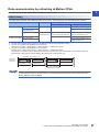
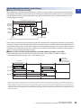
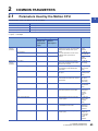
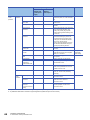
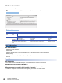
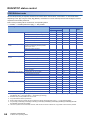
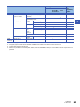
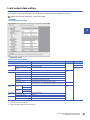
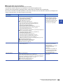
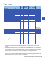
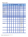
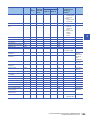
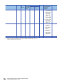
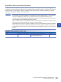
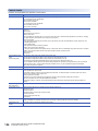
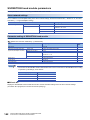
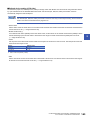
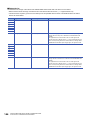
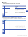
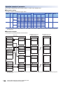
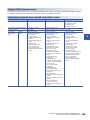
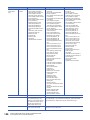
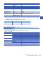
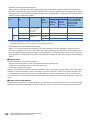
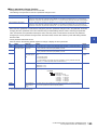
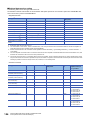
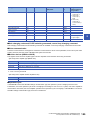
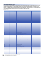
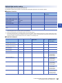
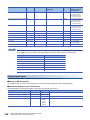
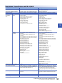
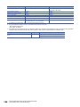
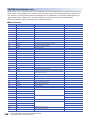
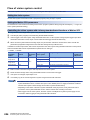
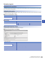
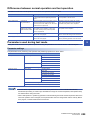
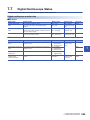
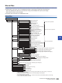
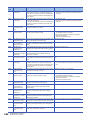
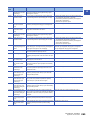
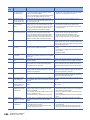
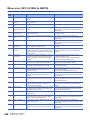
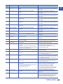
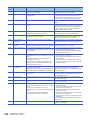
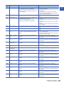
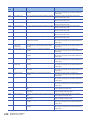
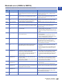
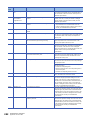
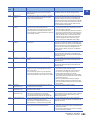
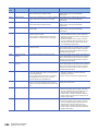
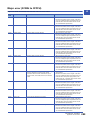
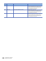
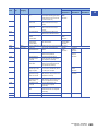
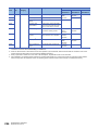
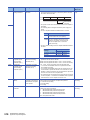
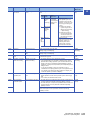
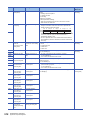
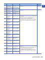
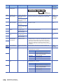
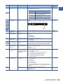
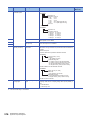
Comparisons of specifications with MR-J3(W)-B Item FR-A700 series*1 MR-J3(W)-□B Amplifier type FR-A700 MR-J3(W)-B, MR-J3(W)-B Fully closed, MR-J3(W)-B Linear, MR-J3(W)-B DD motor Control of servo amplifier parameters Set directly by inverter. (Not controlled by Motion CPU.) Controlled by Motion CPU. External input signal External input signals of FR-A700 series are available. External input signals of servo amplifier are available. Optional data monitor (Data type) Registered monitor Transient command • • • • • • • • • • Motor load factor Position feedback Encoder position within one revolution Encoder multiple revolution counter Load inertia moment ratio Position loop gain Converter output voltage Cumulative current value Torque command value Optional address of registered monitor • • • • • • • • • • • • • • • • • • • Servo amplifier recognition information (First 8 characters) • Servo amplifier recognition information (Last 8 characters) • Servo amplifier software number (First 8 characters) • Servo amplifier software number (Last 8 characters) • Read alarm history number • Alarm history/Detail #1, #2 • Alarm history/Detail #3, #4 • Alarm history/Detail #5, #6 • Alarm history/Detail #7, #8 • Alarm history occurrence time #1, #2 • Alarm history occurrence time #3, #4 • Alarm history occurrence time #5, #6 • Alarm history occurrence time #7, #8 • Alarm history clear command • Main circuit bus voltage • Effective load ratio • Estimate inertia moment ratio • Model loop gain • LED display • Optional transient command Effective load ratio Regenerative load ratio Peak load ratio Position feed back Encoder position within one revolution Encoder multiple revolution counter Load inertia moment ratio Position loop gain 1 Main circuit bus voltage Cumulative current value Servo motor speed Selected droop pulse Load-side encoder information 1 Load-side encoder information 2 Motor thermistor temperature Servo command value Torque command value Optional address of registered monitor 5 • Servo motor ID (SSCNET)/Encoder ID • Encoder resolution • Servo amplifier recognition information (First 8 characters) • Servo amplifier recognition information (Last 8 characters) • Servo amplifier software number (First 8 characters) • Servo amplifier software number (Last 8 characters) • Power ON cumulative time • Inrush relay ON/OFF number • Read alarm history number • Alarm history/Detail #1, #2 • Alarm history/Detail #3, #4 • Alarm history/Detail #5, #6 • Alarm history/Detail/Occurrence time • Alarm occurrence time #1, #2 • Alarm occurrence time #3, #4 • Alarm occurrence time #5, #6 • Alarm history clear command • Home position [command unit] • Main circuit bus voltage • Regenerative load ratio • Effective load ratio • Peak load ratio • Estimate inertia moment ratio • Model loop gain • LED display • Load-side encoder information 1 • Load-side encoder information 2 • Speed feedback • Servo motor thermistor temperature • Optional transient command Absolute position detection system Unusable Usable Home position return method Proximity dog type (1, 2), Count type (1 to 3), Data set type (1), Dog cradle type, Limit switch combined type, Scale home position signal detection type Proximity dog type (1, 2), Count type (1 to 3), Data set type (1, 2), Dog cradle type, Stopper type (1, 2), Limit switch combined type, Scale home position signal detection type, Dogless home position signal reference type Speed-torque control Position control mode, Speed control mode, Torque control mode Position control mode, Speed control mode, Torque control mode, Continuous operation to torque control mode Gain changing command Valid Valid PI-PID switching command Valid Valid 5 FUNCTIONS USED WITH SSCNET COMMUNICATION 5.6 Compatible Devices with SSCNETIII(/H) 163